IgeaCare Systems IGEACOM ANALOG SPEAKERPHONE WITH WIRELESS RECEIVER User Manual 5 x 7 manual
IgeaCare Systems Inc. ANALOG SPEAKERPHONE WITH WIRELESS RECEIVER 5 x 7 manual
USERS MANUAL

igeacom User Guide
V2.0
IgeaCare Systems Inc.
5650 Tomken Road, Unit #9, Mississauga, Ontario, L4W 4P1, Canada
Tel: 905.361.6225 Fax: 905.361.6209 www.igeacare.com
Toll Free: 1.866.361.6225
Part Number 9001001
Quality Care through innovative technology


igeacom User Guide
V2.0
IgeaCare Systems Inc.
5650 Tomken Road, Unit #9, Mississauga, Ontario, L4W 4P1, Canada
Tel: 905.361.6225 Fax: 905.361.6209 www.igeacare.com
Toll Free: 1.866.361.6225
Part Number 9001001
Quality Care through innovative technology
500

igeacom User’s Guide
Version 2.0
FIRST EDITION
July 2004
SECOND EDITION
August 2004
COPYRIGHT
©2004 by IgeaCare Systems Inc. All rights reserved. The content of this document
is for information purposes only and is subject to change without notice. Igeacare
Inc. assumes no liability or responsibility for any errors which may appear within
this document. The material presented herein should not be construed as a com-
mitment or warranty. No part of this publication may be reproduced, transmitted,
transcribed or translated into any language in any form by any means without the
express written permission of IgeaCare Systems Inc.
SOFTWARE LICENSE NOTICE
Your license agreement with IgeaCare Systems Inc., which is included with the
product, specifies the permitted and prohibited uses of the product. Any unautho-
rised duplication or use of igeacom Version 2.0 in whole or in part, in print, or in
any other system is prohibited.
LICENSES AND TRADEMARKS
Macintosh is a trademark of Apple Computer, Inc.
The IgeaCare logo is a registered trademark of IgeaCare Systems Inc.
QuarkXpress is a registered trademark of Quark, Inc.
Adobe Photoshop is a registered trademark of Adobe Systems Incorporated.
All other brand or product names mentioned in this user’s guide are trademarks or
registered trademarks of their respective holders.
This document has been produced using QuarkXpress.
All graphics have been taken from the IgeaCare application using Windows Print
Screen function and enhanced using Adobe Photoshop.
IgeaCare Systems Inc. wishes to sincerely thank all of the individuals who made
this product possible
igeaCare systems Inc.
5650 Tomken Road, Unit #9, Mississauga, ON L4W 4P1
Visit our Web site at: www.igeacare.com
Printed In Canada

Contents
Section 1 - User Overview
Requesting Help . . . . . . . . . . . . . . . . . . . . . . . . . . . . . . . . .1-3
Cancelling a Call . . . . . . . . . . . . . . . . . . . . . . . . . . . . . . . . .1-4
Increasing/Decreasing Volume . . . . . . . . . . . . . . . . . .1-4
Retrieving Menus & Activities . . . . . . . . . . . . . . . . . . .1-5
Indicator Lights . . . . . . . . . . . . . . . . . . . . . . . . . . . . . . . . . .1-6
Line Indicator . . . . . . . . . . . . . . . . . . . . . . . . . . . . . . . .1-6
Fault Indicator . . . . . . . . . . . . . . . . . . . . . . . . . . . . . . . .1-7
Activities Indicator . . . . . . . . . . . . . . . . . . . . . . . . . . .1-8
Menu Indicator . . . . . . . . . . . . . . . . . . . . . . . . . . . . . . .1-8
Indicator Lights warning Chart . . . . . . . . . . . . . .1-9
Section 2 - Circuit Board Overview
Overview . . . . . . . . . . . . . . . . . . . . . . . . . . . . . . . . . . . . . . . .2-3
Internal Hardwire Input connections . . . . . . . . . . . .2-5
Section 3 - Diagnostic Procedures
Diagnostic Procedures during Boot-up . . . . . . . . . .3-3
Section 4 - Programming
Overview . . . . . . . . . . . . . . . . . . . . . . . . . . . . . . . . . . . . . . . .4-3
1.0 Parameters . . . . . . . . . . . . . . . . . . . . . . . . . . . . . . . . . . . .4-3
2.0 Calling . . . . . . . . . . . . . . . . . . . . . . . . . . . . . . . . . . . . . . . .4-4
2.1 Hardwire Buttons . . . . . . . . . . . . . . . . . . . . . . . .4-4
2.2 RF Modules . . . . . . . . . . . . . . . . . . . . . . . . . . . . . . .4-4
3.0 Call Recognition . . . . . . . . . . . . . . . . . . . . . . . . . . . . . .4-4
4.0 Cancelling . . . . . . . . . . . . . . . . . . . . . . . . . . . . . . . . . . . .4-5
5.0 Redialing . . . . . . . . . . . . . . . . . . . . . . . . . . . . . . . . . . . . . .4-6
6.0 Call Priority . . . . . . . . . . . . . . . . . . . . . . . . . . . . . . . . . . .4-7
7.0 RF Modules Learning Process . . . . . . . . . . . . . . . .4-7


User Overview
1

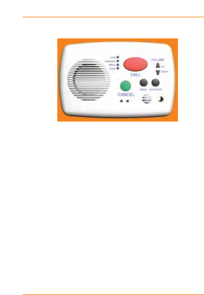
Using the igeacom Emergency Call Device:
The igeacom emergency call device is easy to use.
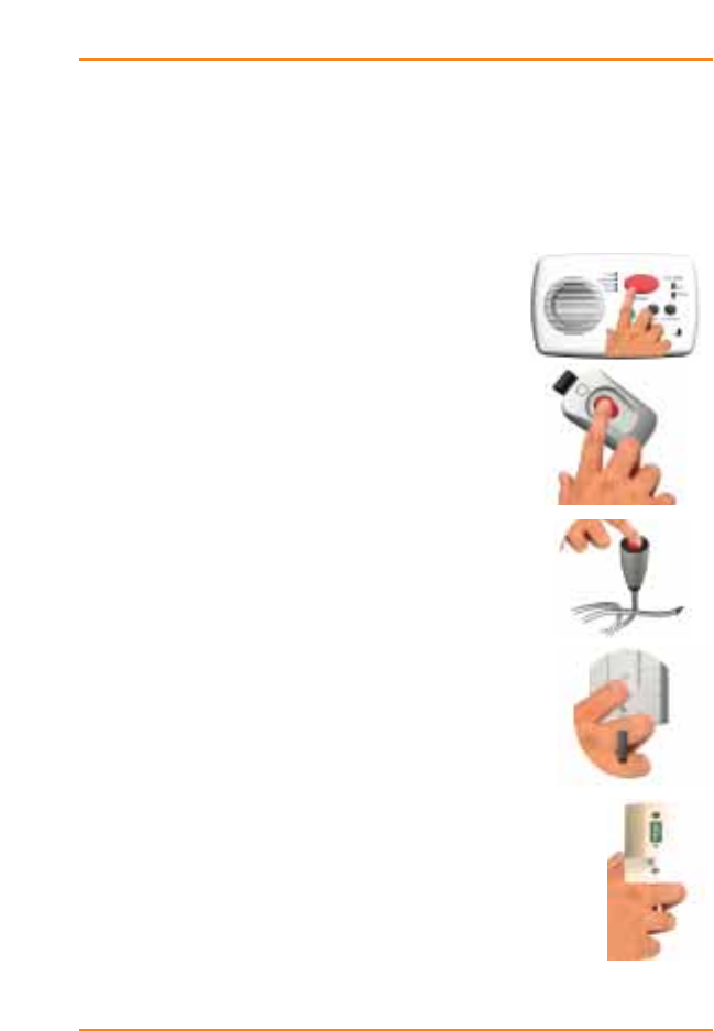
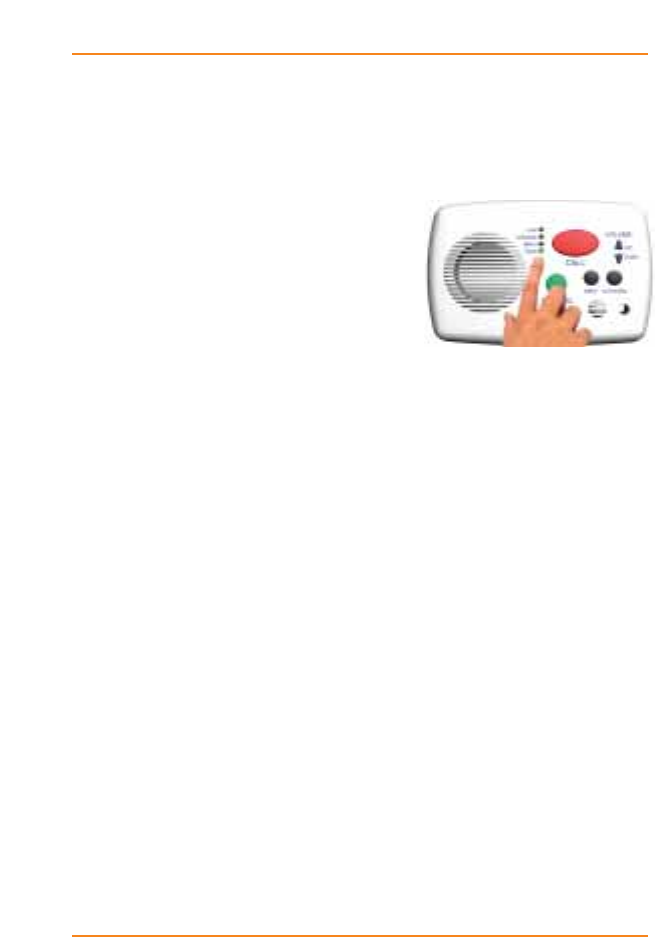
Requesting Help:
›To Request Help:
Press the red call button on the unit,
or
Press the red button on the pendant,
or
Press the red button on the push cord
or
Toggle any of the pull cords.
By activating any one of the peripheral
devices your igeacom emergency call
device will send a signal to the
emergency call unit to call the emergency
call station or control center.
All of your peripheral devices can be
programmed according to their priority
or associated degree of emergency as
programmed by the facility for each device.
1-3
User Overview
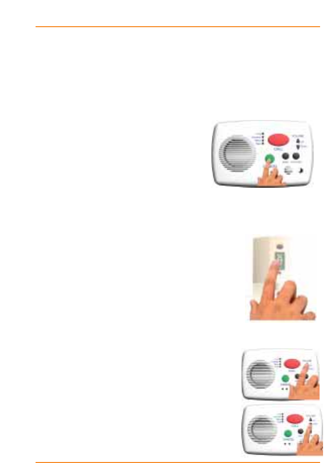
Cancelling a call:
If you accidentally activate an alarm call you can cancel
the call from the emergency call unit.
›To Cancel a Call: (Emergency Call Unit)
Press the green cancel button.
The wireless pull cord can also be
cancelled at the source.
›To Cancel a Call: (Wireless Pull Cord)
Push down on the cancel area.
If the call is accepted by the operator
prior to cancelling the call, simply
explain to them it was an error and the
operator or yourself can then cancel the
call.
Increasing/Decreasing Volume
It is easy to increase or decrease the
volume of your emergency call device.
›To Increase the Volume:
Press the up arrow
›To Decrease the Volume:
Pressing the down arrow.
1-4
User Overview
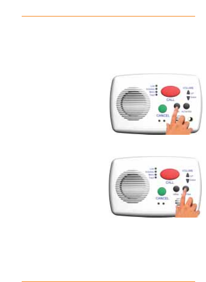
Retrieving Menus & Activities
The black buttons labeled Menu and Activities on the
igeacom emergency call unit activate the menu or activity
announcements for the week or day, as programmed by
your facility.
›To Retrieve the Menu
Hold down the black Menu
button to hear a pre-recorded
announcement.
›To Retrieve Activities
Press the black Activities
button.
1-5
User Overview
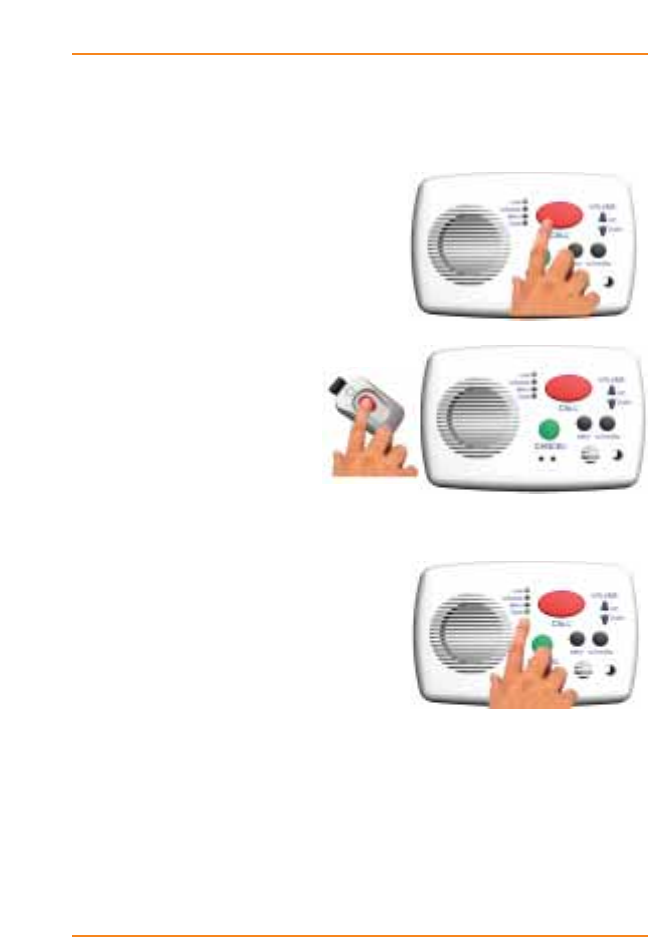
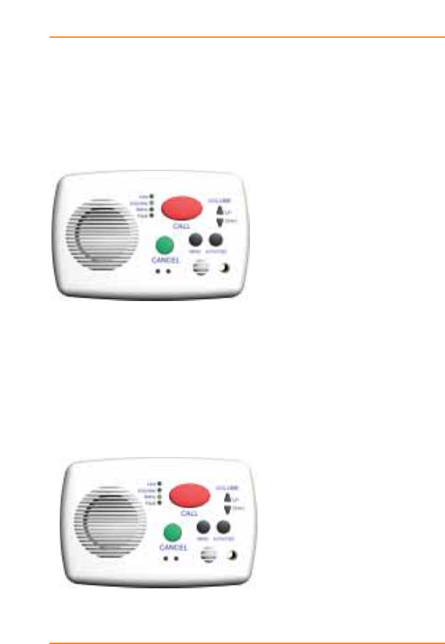
Indicator Lights
Line Indicator:
The Line indicator LED will turn on when:
a) The call button has been
pressed,
b) An igeacom device,
e.g. the pendant,
has been triggered.
The Line LED will also appear in
combination with the Fault LED indicator if:
a) the emergency call device
detects a fault in the line.
If the Line or Fault LED remains
on for a period longer than 20
seconds then the resident should inform the central sta-
tion or operator immediately. The Line LED will flash
every 5 minutes along with the Fault LED should a prob-
lem be indicated. If both LED’s appear the resident
should inform the central station or operator immediately.
1-6
User Overview
Fault Indicator:
The Fault indicator LED indicates that there is a
possible fault with your emergency call device.
If the Fault LED indicator appears
you should immediately contact
the operator and request assistance
so that your system can be exam-
ined and/or repaired.
The Fault LED indicator will appear if the emergency call
device detects a fault in the keypad, line or unit.
1-7
User Overview
Activities Indicator:
The Activities LED indicator will turn on/flash when the
menu button has been pressed.
Menu Indicator:
The Menu LED indicator will turn on/flash when the
menu button has been pressed.
1-8
User Overview

1-9
User Overview
Light Indicator
Lit Condition Solution
Line Call button pressed If assistance not
required cancel the
call to reset unit.
Line Device triggered, e.g.
pendant If device is not in use
turn it off.
Line & Fault Fault in line. When a
no line fault occurs a
short chirp will sound
of 70ms in duration
Call Operator
immediately
Fault Fault in keypad. When
a keypad error occurs
a short chirp will sound
for 70ms in duration.
Call operator
immediately
Fault Fault with unit Call Operator
immediately
Activities & Fault
Activities, Line & Fault
Battery warning. The
device will chirp (2
beeps) for a duration
of 160ms.
Battery life is low a
long chirp will sound
for 560ms.
Call Operator
immediately.
Battery should be
recharged.
Call Operator
immediately.
Replace Battery
Indicator Lights Warning Chart

Warranty
If you would like to report a fault or return an igeacom device for warranty repair,
please complete the online form at: http://www.igeacare.com/support.htm
All igeacom devices have a one year warranty against manufacturer defect. The
igeacom wireless pull cord battery and wireless pendant battery have a five year
warranty.
Please register your igeacom device online at:
http://www.igeacare.com/support.htm
The igeacom 100, 300 and 500 are CSA certified:
1) Class 481205
CSA Std C22.2 No. 205 - m1983 signal equipment;
CAN/CSA - 22.2 No. 60950 -1-03;
Bi-national standard with UL 60950-1
2) CSA-US
Class 481284
Class 481204
CSA Std C22.2 No 205-m1983;
UL Std No. 464, Eight ed 2003
CAN/CSA 22.2 No. 60950-1-03;
Bi-National standard with UL 60950-1
3) igeacom300 & igeacom500
FCC ID:SEDIGEACOM
IC: 5263A-IGEACOM
Operation is subject to the following two conditions: (1) This device may not cause
interference, and (2) This device must accept any interference, including interference
that may cause undesired operation of the device.
"NOTE: THE MANUFACTURER IS NOT RESPONSIBLE FOR ANY RADIO
OR TV INTERFERENCE CAUSED BY UNAUTHORIZED MODIFICATIONS TO
THIS EQUIPMENT. SUCH MODIFICATIONS COULD VOID THE USER'S
AUTHORITY TO OPERATE THE EQUIPMENT."
1-10
Overview

Circuit Board Overview
2

Circuit Board(s)
The igeacom combines all your communication needs
into one system. The igeacom is available in two models,
the igeacom300 and igeacom500. The igeacom300 can
easily be upgraded to include all the peripheral devices
of the igeacom500.
TAV011 (Main Board) TAV011 (Main Board)
TAV012 (Keypad Board) TAV012 (Keypad Board)
TAV014 (Receiver Board)
TAV013 (Output Relay Module)
TAV020 (Personal RF Pendant)
TAV030 (Wall RF Pendant)
2-3
Circuit Board Overview
500
300

All circuit boards indicate PCB manufacturer logo and UL
listing. Boards are 1/16" thick made from FR-4 material.
There is no handset or metal contacts for the end user.
The igeacom is permanently fixed to a wall and installed
into a standard three gang box.
The igeacom is line powered (phone line); its on hook
current consumption is approximately 1.5mA and its off
hook current consumption is approximately 27mA.
There are several keypads to dial pre-arranged numbers.
There are also two peripheral devices (TAV020, TAV030),
which trigger pre-arranged numbers for the main board
to dial.
The pre-arranged phone numbers are all downloaded into
the igeacom via an infra-red communication link. All of
these devices are low powered.
2-4
Circuit Board Overview
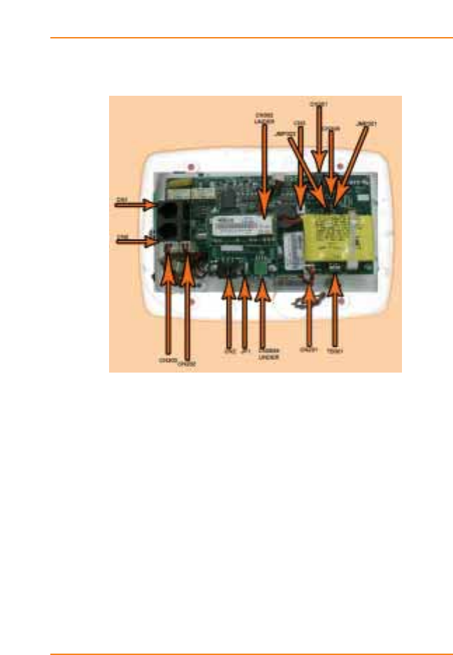
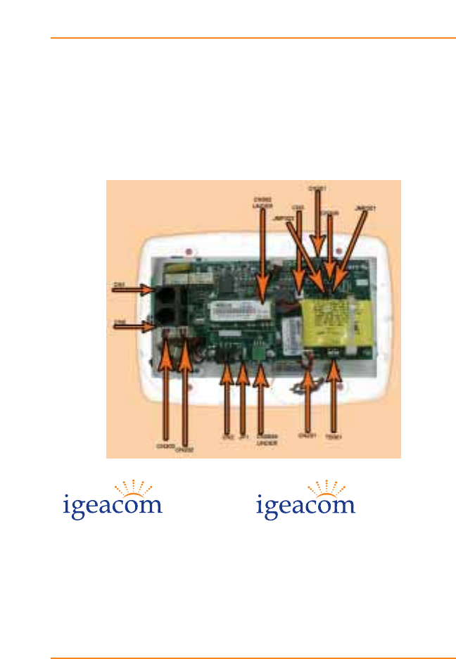
Internal Hardwire Input Connections
for TAV011 (Main Board)
Connector Use
CN1 One telephone input line cord (40mA-50mA)
with standard modular telephone plug.
CN2 One telephone output line cord (40mA-50mA)
with standard modular telephone plug.
It is used as an extension for a telephone.
CN3 Two pin header is used for the connection of
the Ni-Cd 3.6V battery pack assembly.
TB301 Terminal block hook up is for normally open
contacts such as wall mount pull cords.
2-5
Circuit Board Overview

CN301 Six pin connector is used for updating and
reading the software (within the micro-
controller U301) responsible for the function
of the entire igeacom unit.
Note: Only a qualified technician should be using
this connector.
CN302 Eight pin socket is used for the connection
of the Keypad board TAV012.
CN303 Three pin header is for the phone jack
connection, which is a normally open contact.
CN305 Eight pin socket is used for the connection
of the Receiver board TAV014.
CN306 Six pin socket is used for the connection of
the Output Relay Module board TAV013.
CN201 Two pin header is used for the connection of
the speaker assembly.
CN202 Two pin header is used for the connection of
the microphone assembly.
TAV030 (Wall RF-Pendant)
This device transmits at 433.92MHz with OOK modula-
tion. The maximum current transmission is 10mA. The
transmitter is also a third party device.
2-6
Circuit Board Overview

Diagnostic Procedures
3


Diagnostic Procedures during Boot-up:
Before mounting the igeacom unit, the battery must be
plugged into connector CN3.
Please note the igeacom will then perform the following
diagnostics:
1. An audio beep along with the 4 front LED's
turn on for a duration of 600 ms. ( ____ ).
This tells the installer that the unit has booted up
properly and that the battery is okay. If this
condition is not met the unit must be replaced.
2. Three audio beeps for a duration of 200 ms
each ( __ __ __ ).
This indicates that the unit has gone through the
cancellation routine which prepares the unit for
standby mode. If this condition is not met the unit
must be replaced.
3. The unit checks for two more conditions:
a. The unit will check to see if a telephone line has
been connected to CN1.
Since we have not hooked up a telephone line yet the
unit will chirp and the Line and Fault LED's will
light up for a duration of 50 ms.
3-3
Diagnostic Procedures

b. The unit will check to see if any buttons have
seized and check battery conditions.
If this occurs the unit will chirp and the Fault
LED will light up for a duration of 50 ms.
Note:
i. In standby mode every 5 minutes the unit will
perform diagnostic check (3) of the unit and check
for all the items listed on page 1-9.
ii. While in working mode the unit will perform
diagnostic check (3) continuously.
iii. If all of the above parameters pass, then plug
the telephone line into CN1 and the telephone
extension into CN2.
Press the Cancel button.
This verifies and checks step 1-3 again.
You will notice that step 3 (B) will not occur. If it does occur the
unit must be replaced.
4. The unit can also perform the diagnostic
procedure by simultaneously pressing the
Menu & Activities buttons, it will:
i. Check for the line;
ii. Check for a battery warning;
iii. Check to see if the battery voltage is low;
iv Check to see if the keypad has a seized button.
3-4
Diagnostic Procedures

5. If the fault light appears on the unit,
simultaneously followed by the sound of
2 short chirps 90 ms each, then this indicates:
i. The battery is below operating voltage;
ii. The battery is not plugged in, or
iii. The battery is damaged
When the unit detects this fault, the unit will lock you out
from making a call until the unit has been looked at by
the site technician.
To reset the unit simply press the Menu, Activities,
Cancel and Volume buttons simultaneously.
The unit is now ready to be securely mounted to the wall.
3-5
Overview


Programming
4

Overview
The igeacom is fully programmable via infra-red link.
›To place igeaCom into Infra-red Download Mode:
Simultaneously press both Volume buttons for approxi-
mately 5 seconds.
›To End Infra-red Download:
Once the parameters are downloaded and verified press
both Volume buttons to end system download.
1.0 Parameters
The parameters that we can download are:
1.1 Phone Numbers
1.2 Redial Delays
1.3 Redial Yes/No
1.4 Silent Dialing Yes/No
1.5 Color Dome Light White/Green/Red/Blue
1.6 Priority (from Highest =1 to Lowest=6)
4-3
Programming

2.0 Calling
The call can be done via hard wired buttons or RF modules:
2.1 Hard wired buttons:
2.1.1.1 Red Call Button
2.1.1.2 Pull Cord
2.1.1.3 Emergency Cord (plugs into jack)
Push Button Call Cord
2.2 RF modules
2.2.1.1 RF pendant
2.2.1.2 RF Wall-mount (this unit also has a cancel
RF button)
3.0 Call Recognition:
3. Call recognition is accomplished by dialing *3
on any wired or wireless telephone.
3.1 If the recipient performs the call recognition
code by phone he/she will hear acknowledge-
ment tones to verify the call has been recognized.
4-4
Programming

3.2 If the recipient performs the call recognition
code and is talking on the phone for a duration
of 4 minutes the recipient of the call will hear
two warning tones for a duration of 100 ms each
( __ __ ) on his/her phone.
These tones indicate that 4 minutes of talk
time have passed and that there is only 1
minute left to talk to the caller. These tones will
sound off every 10 seconds until 5 minutes
have passed. After 5 minutes the call will hang
up and redial the same number. The 5 minutes
window is factory set and cannot be changed
by the user.
Note:
Each time the recipient enters *3 the 5 minute
window will be reset, allowing the recipient to
remain on the line with the caller.
4.0 Cancelling
The Cancel Operation can be done in two ways:
4.1 Pressing the green Cancel button
4.2 By phone, dialing *9.
If the recipient performs the cancel operation
by phone he/she will hear the acknowledgement
tones to verify the call has been cancelled.
Note:
These tones sound different from the Call
Recognition tones.
4-5
Programming

5.0 Redialing
If the call is not answered within the time named Redial
Delay (1.2), system may:
5.1 Dial the next phone number, if the parameter
named Redial (1.3) is programmed Yes.
5.2 Hang up, if the parameter named Redial (1.3)
is programmed No.
If the call is answered:
5.3 If the call is answered and the recipient hangs
up without Call Recognition (3) or Cancel
Operation (4) then Redialing takes place once
the Redial Delay (1.2) has passed for that call.
5.4 If the call is answered and the recipient does
not enter the Call Recognition (3) the following
will occur:
While talking on the phone the Redial Delay
(1.2) continues to count down, once the Redial
Delay timer has reached the specified delay
time the unit will hang up and proceed to
steps 5.1 and 5.2.
5.5 If the call is answered and the recipient
acknowledges the call with the Call Recognition
(3) and then hangs up without the Cancel
Operation (4) the call will redial the same
number within 5 minutes from hang up
4-6
Programming

6.0 Call Priority
6.1 To any calling button (hard wired and RF)
is associated a programmable priority
(parameter 1.6). The most urgent button can
interrupt the less urgent one.
Note:
The Menu and Activities buttons have the
lowest priority.
7.0 RF Module Learning Process
The RF modules (2.2.1.1 and 2.2.1.2) will be learned by
the system, following this procedure:
7.1 Put the system into learn mode by pressing
the Cancel and Menu buttons simultaneously
for approximately 5 seconds.
7.2 Activate the RF module. The system will
confirm the End of Learning Process by a long
beep, passing automatically to normal mode.
4-7
Programming
