Image Sensing Systems RTMS-K4 RTMS K4 User Manual
Image Sensing Systems, Inc. RTMS K4
UserManual.wiki
>
Image Sensing Systems
>
RTMS K4 User Manual
User Manual
Navigation menu
Upload a User Manual
Namespaces
Wiki Guide
HTML
PDF
Info
Views
User Manual
Discussion / Help
Navigation


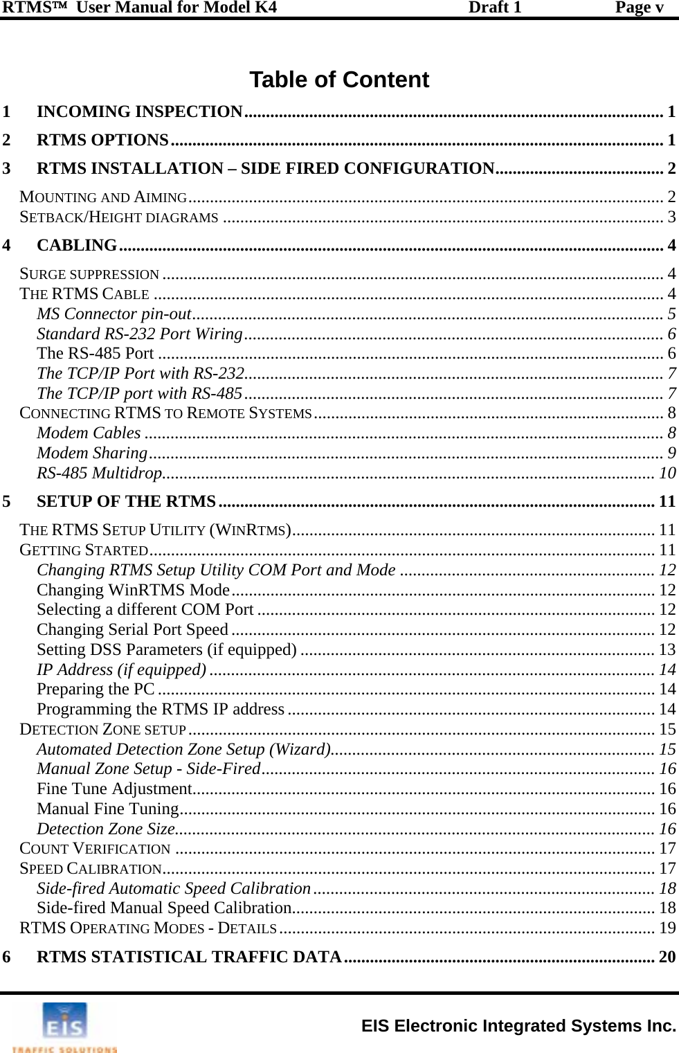
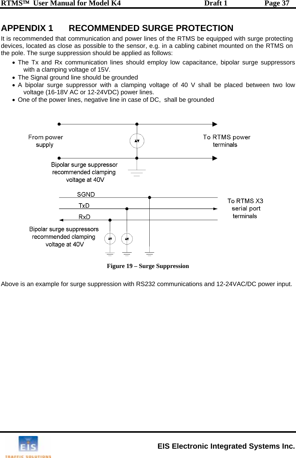
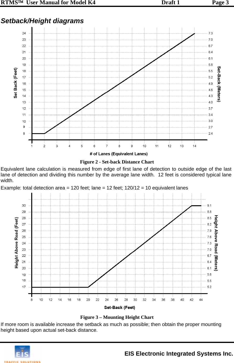
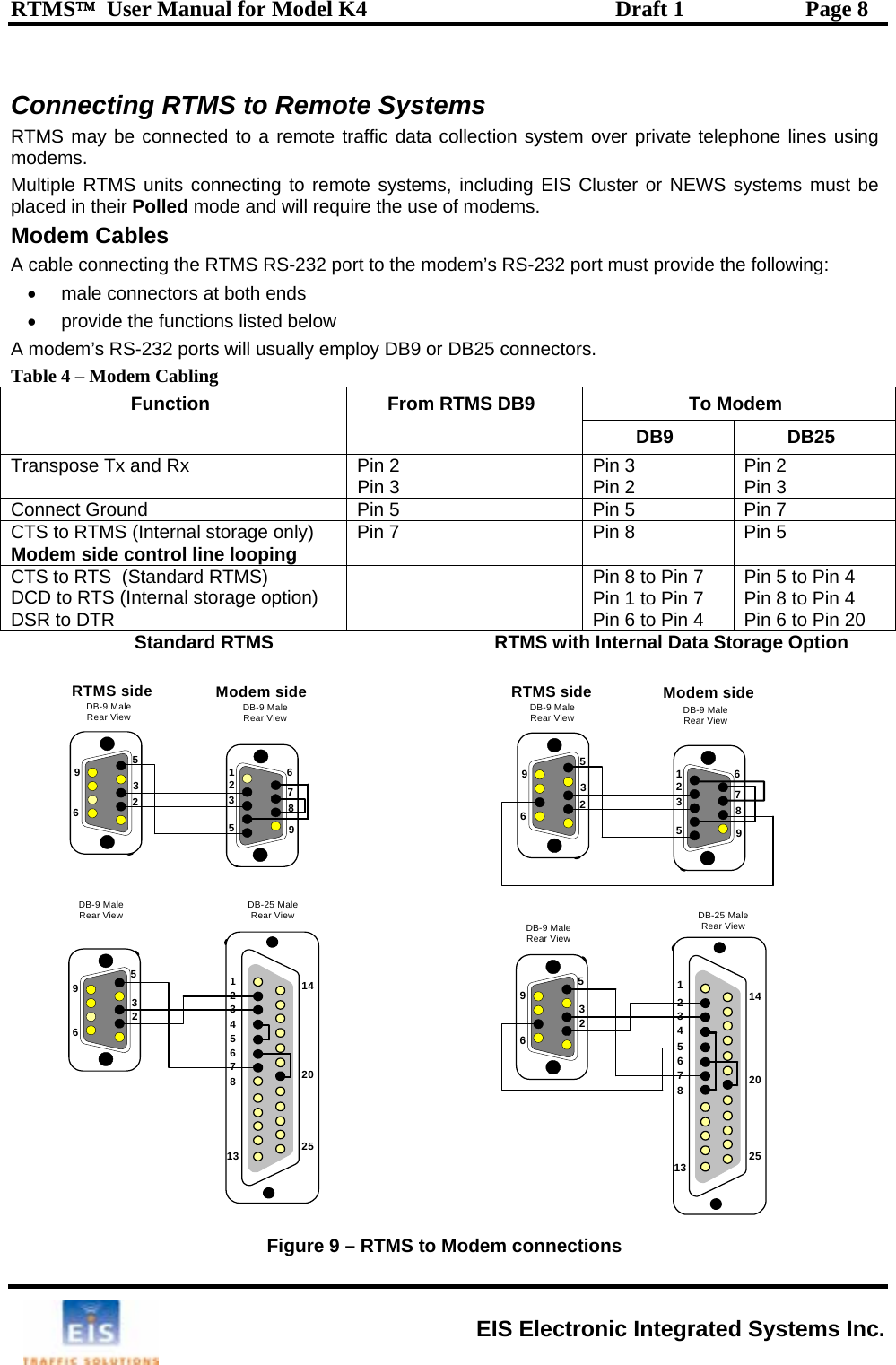
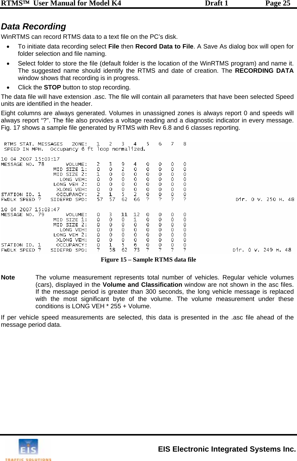
![RTMS™ User Manual for Model K4 Draft 1 Page 2 3 RTMS INSTALLATION – SIDE FIRED CONFIGURATION Mounting and Aiming The distance between the close edge of the first lane of traffic to be monitored and the front of the structure on which the RTMS is mounted is referred to as set-back; it is the most important parameter in the setup and installation of an RTMS. Generally the more set-back that can be obtained, the easier the calibration will be. Use the diagram in Figure 2 to determine the setback required to monitor a given number of lanes. Once the set-back is set, the associated height can be determined. Height is with reference to the road surface of the detection area; not the bottom of the mounting pole. Example: For 5 lanes the minimum set-back should be 12 feet [3.7m]. A set-back of 12 feet [3.7m], requires a height of 17 feet [5.2m]. Note: It is better to be 20 feet [6 m] further back from the minimum than 2 inches [5 cm] closer than the minimum. If ground conditions allow, move the RTMS further back. The mounting height is based on the setback. Height is selected to allow the RTMS to be aimed so that it gets maximum return signal while covering all required lanes. Mounting an RTMS at a height different from the recommended height will not improve accuracy. Equivalent lanes include median strips, as an example, an eight lane road with a two lane wide median strip has 10 equivalent lanes. •Boresight line Figure 1 – RTMS Aiming • Attach the RTMS to the roadside pole using bolts or stainless steel banding. • Aim the RTMS as indicated on the diagram above. A 7/16” wrench is required to release/tighten the ball-joint bolt. - Secure the RTMS to the mounting bracket by inserting the lynch pin - Adjust the RTMS to be perpendicular to the travel lanes. - Look from behind the unit and use the top aiming fin to tilt so that the top of the RTMS is aimed to the first 1/3 of the monitored lanes. - Keep the RTMS level, side to side. - Lock the aim by tightening the ball-joint bolt. EIS Electronic Integrated Systems Inc.](https://usermanual.wiki/Image-Sensing-Systems/RTMS-K4/User-Guide-837554-Page-9.png)
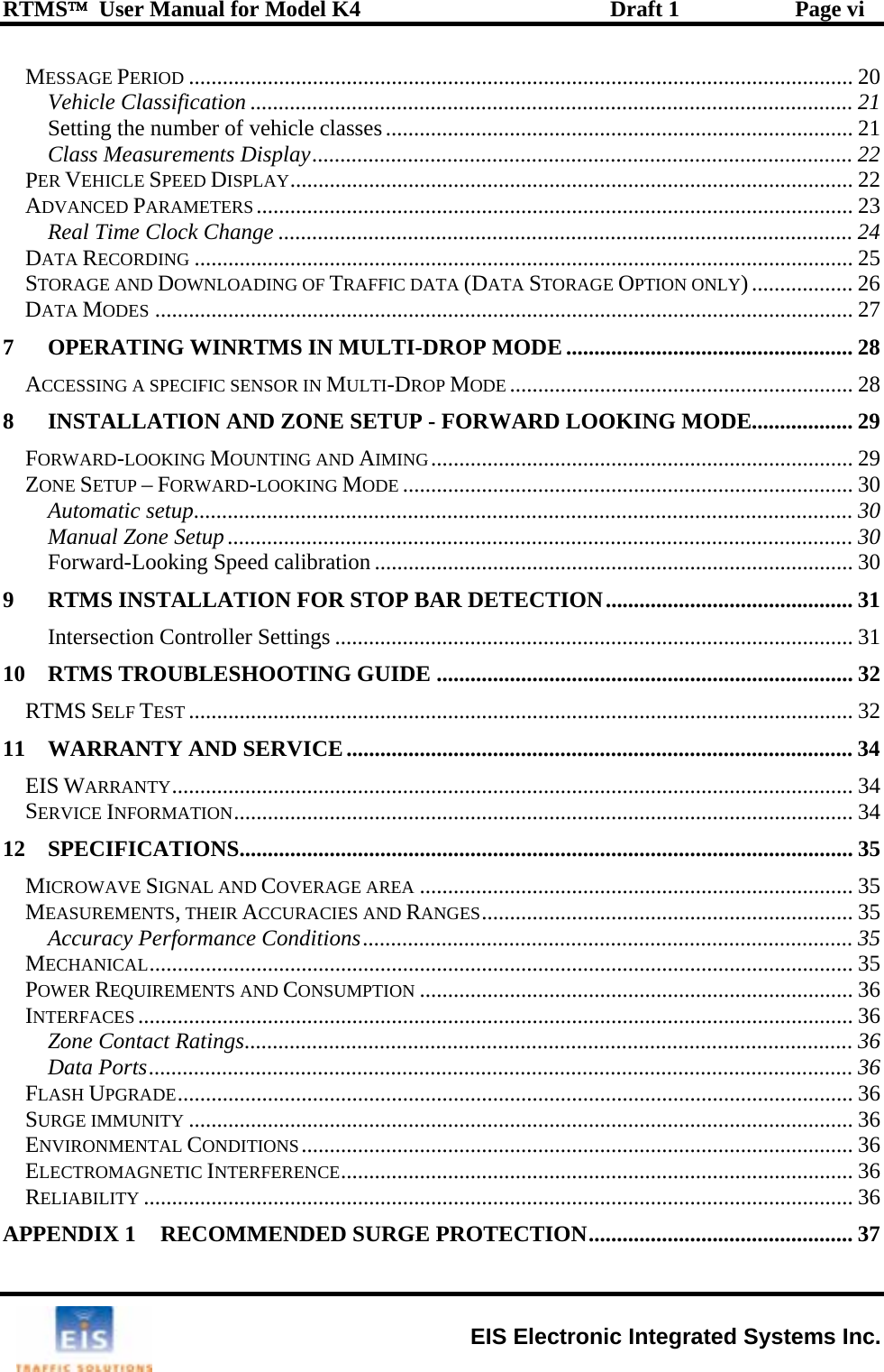
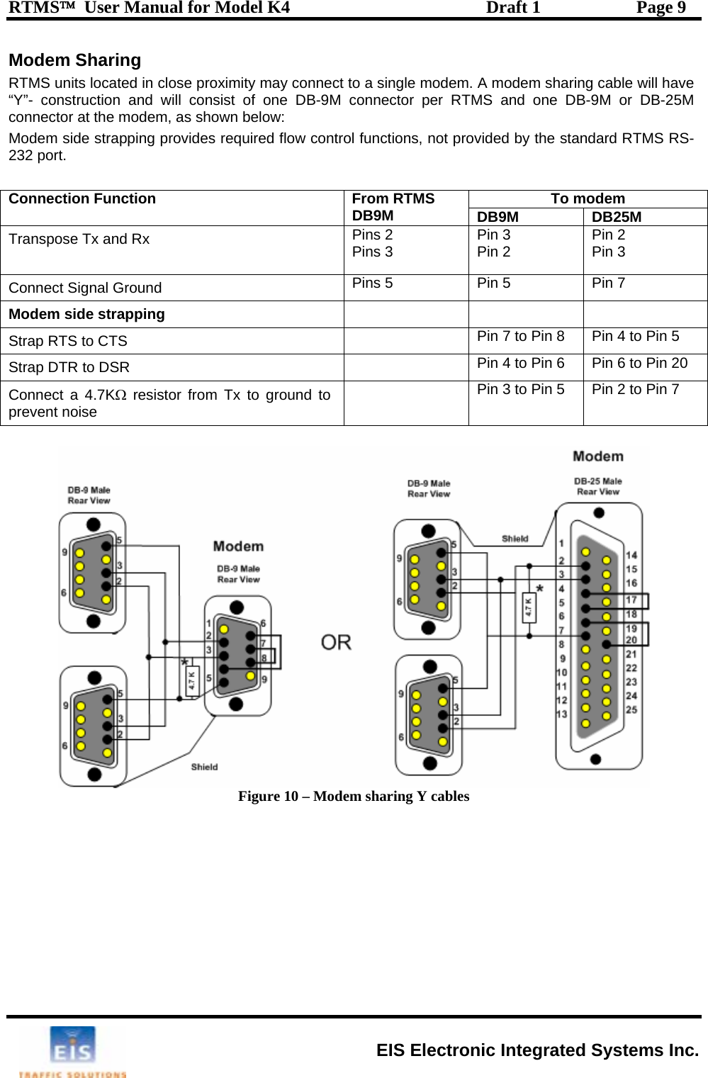
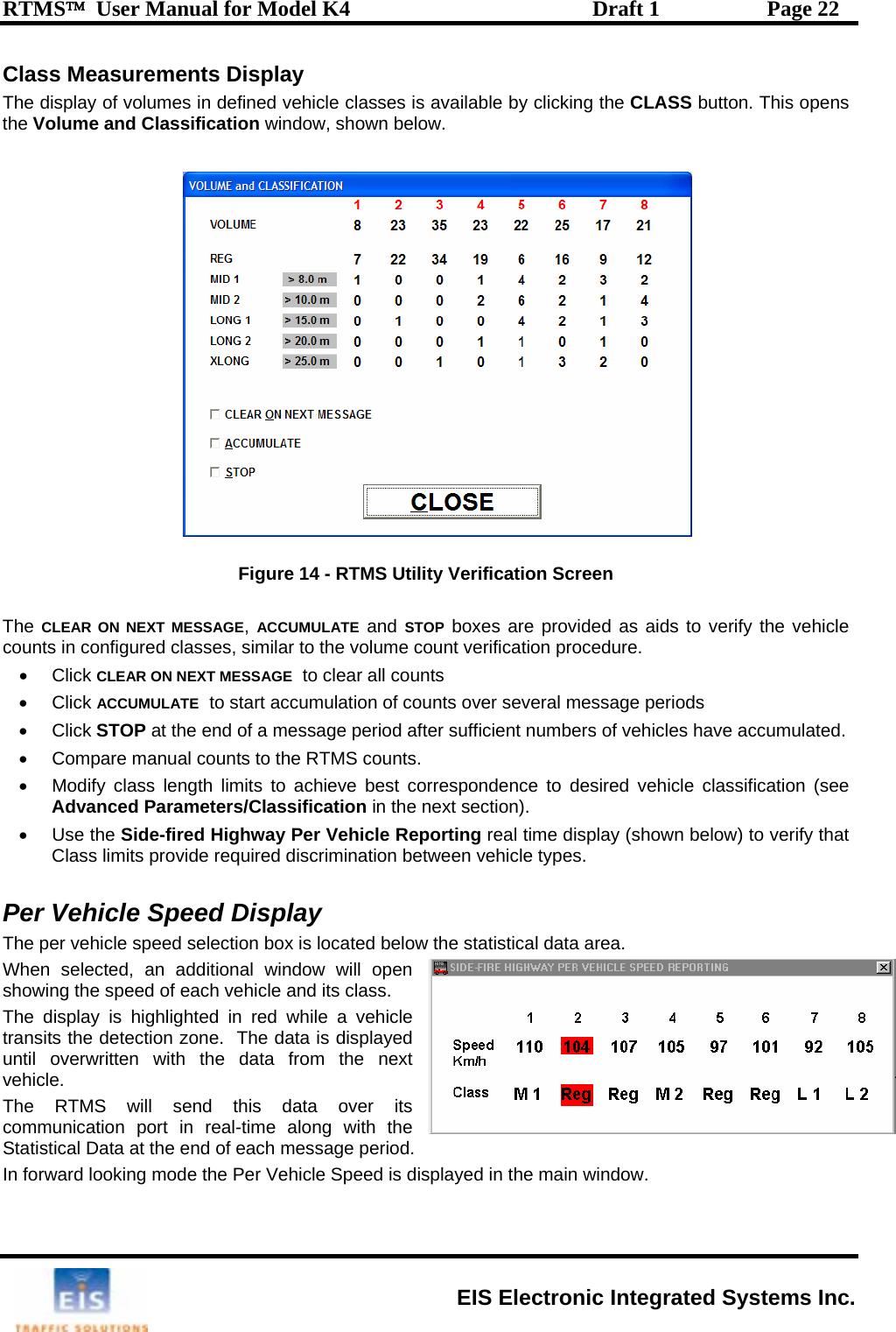
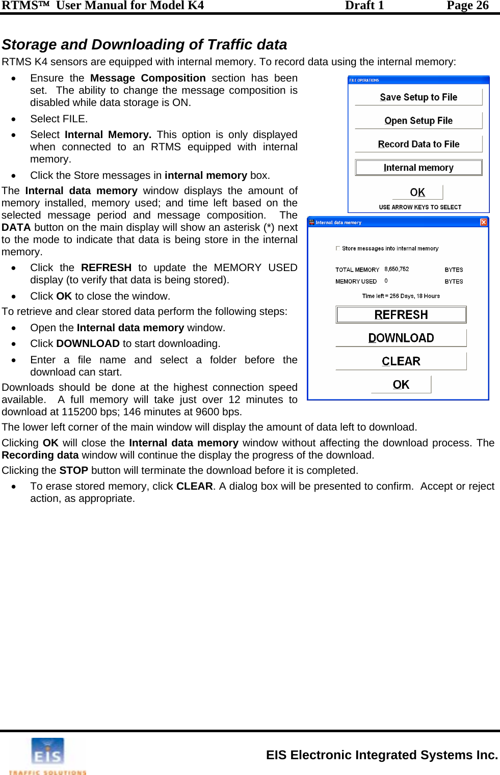
![RTMS™ User Manual for Model K4 Draft 1 Page 7 The TCP/IP Port with RS-232 CAT5 cable must be used for lengths between 30 ft [10m] and 330 ft [100m]. Lengths greater than 330 feet are not supported for Ethernet communication. It is recommended that both TCP/IP and RS-232 ports be brought out to their respective connectors, as shown. Only one port may be in use at a time. The RS-232 port is useful for setup and maintenance purposes. Figure 7 - TCP/IP Wiring Diagram Note: There are no extra cabling requirements when Internal Memory is installed with a unit communicating over TCP/IP. The TCP/IP port with RS-485 Figure 8 - TCP/IP with RS-485 Wiring Diagram EIS Electronic Integrated Systems Inc.](https://usermanual.wiki/Image-Sensing-Systems/RTMS-K4/User-Guide-837554-Page-14.png)
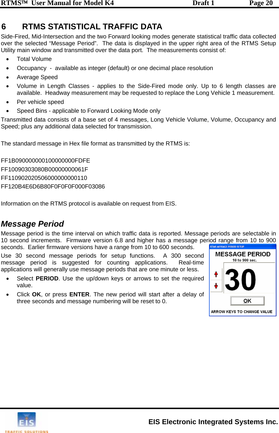
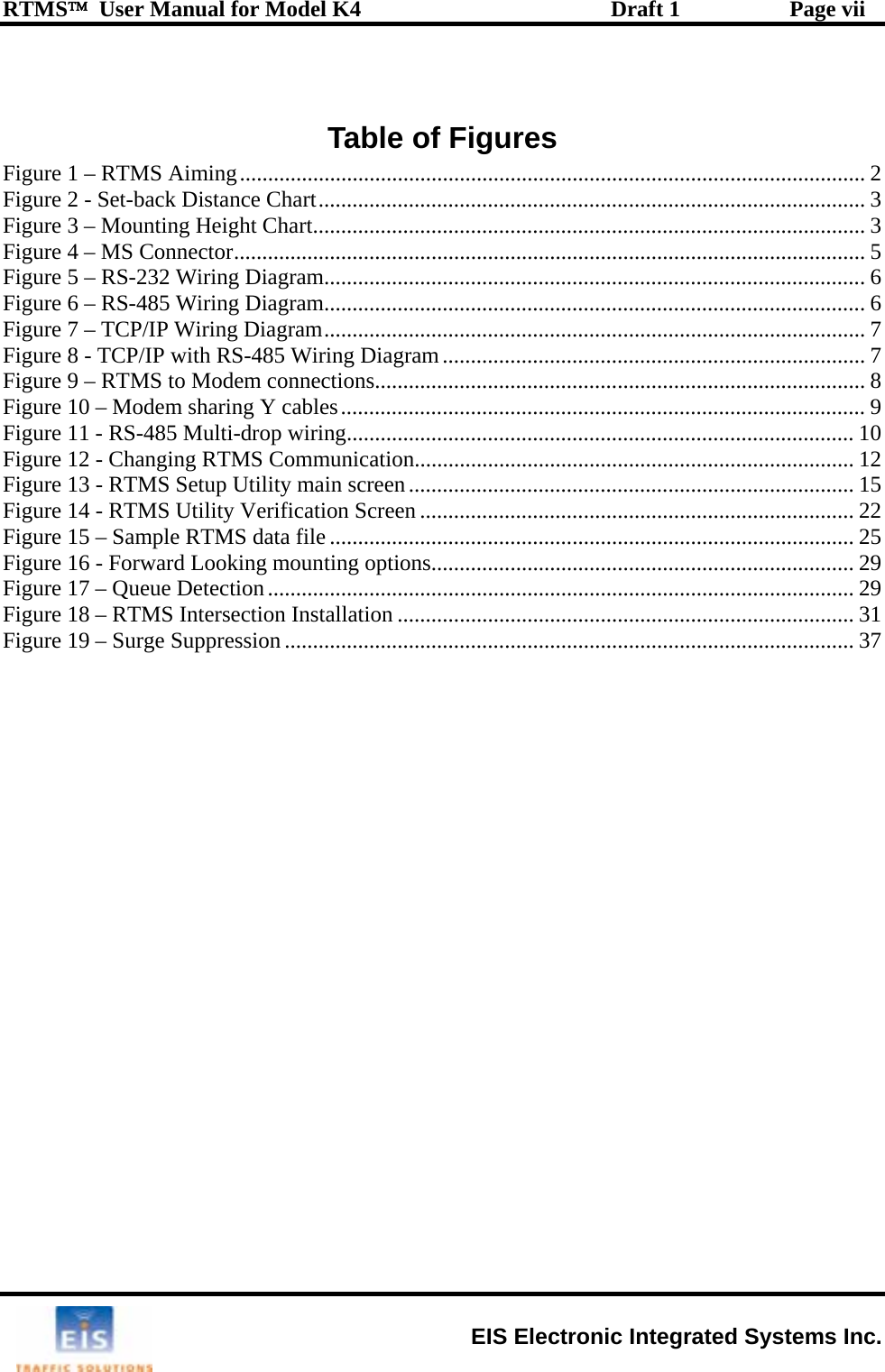
![RTMS™ User Manual for Model K4 Draft 1 Page 21 Vehicle Classification Setting the RTMS for vehicle classification (side-fired mode only) is a two stage process: 1. Defining the number of classes. 2. Defining the class boundaries. SThe o . vehicle volumes only. vehicle volume, volume, occupancy and speed). messages 2 messages s window, open the SIFICATION and ngths defined. Only the length classifications that were chosen will show on this screen. e ti• Select DATA mt ng the number of vehicle classes ode then Message composition. Statistical message setup window will pen • Select 2, 4 or 6 classes 2 Classes (default) provides the reporting of long Transmitted data will consist of 4 messages: (long 4 Classes adds Mid and XLong6 Classes adds Mid2 and Long• After completing selections in thiADVANCED menu, select CLASdefine the classes selected. he length of cars is pre-set, only vehicles longer than cars can have Tlein the classification menu For best results, ensure that length differences are greater than 3m [10 feet] between size classifications. The closer the separation the greater the potential “merging” of classes. EIS Electronic Integrated Systems Inc.](https://usermanual.wiki/Image-Sensing-Systems/RTMS-K4/User-Guide-837554-Page-28.png)
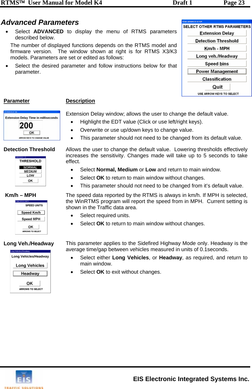
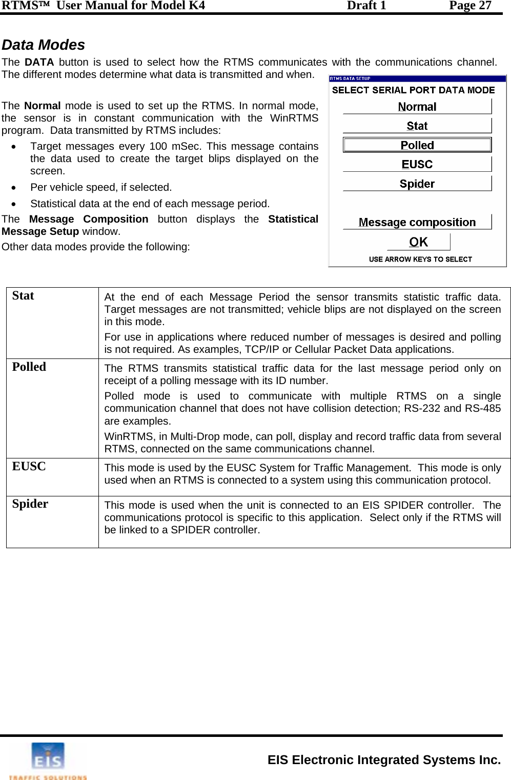
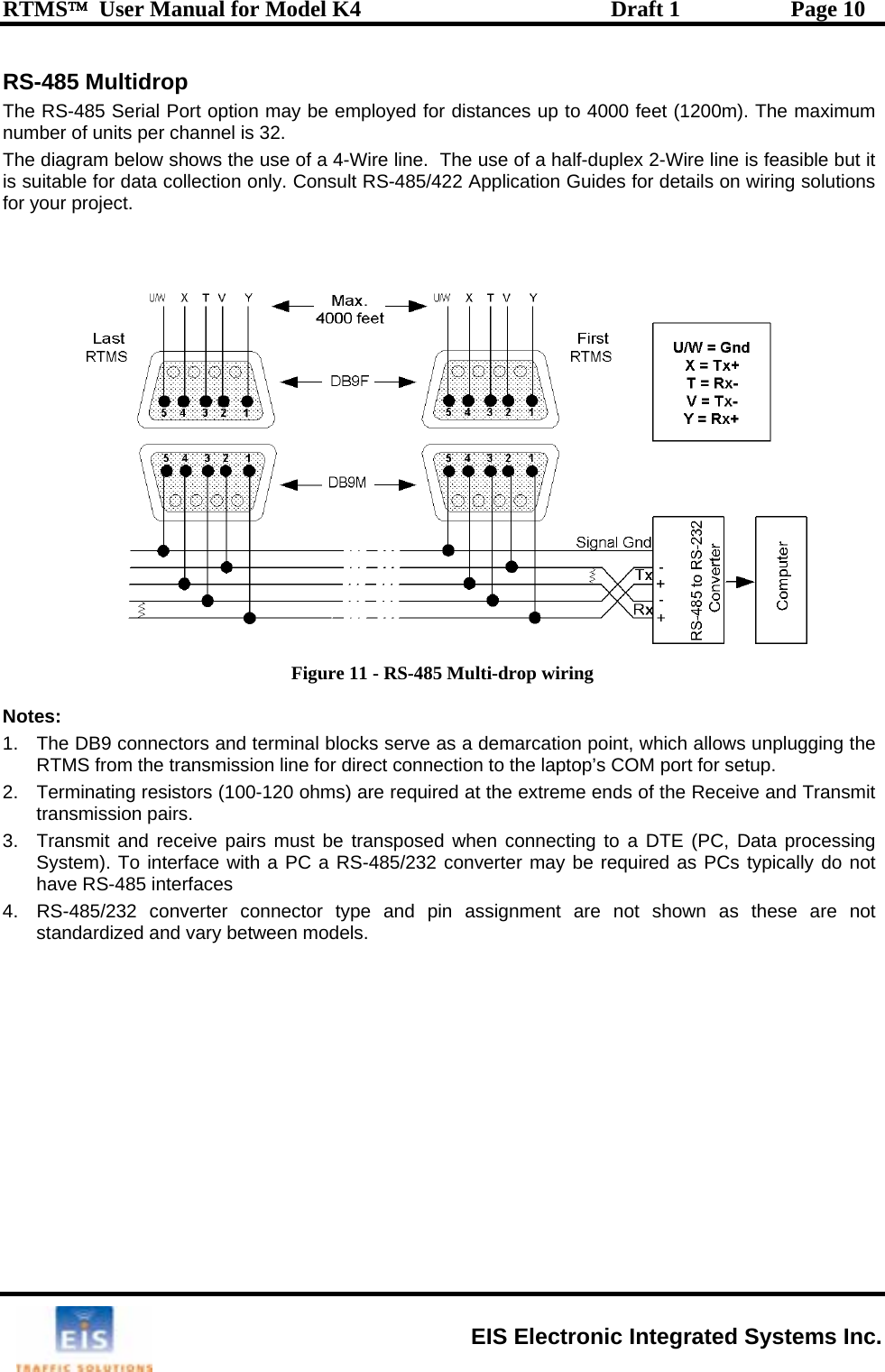
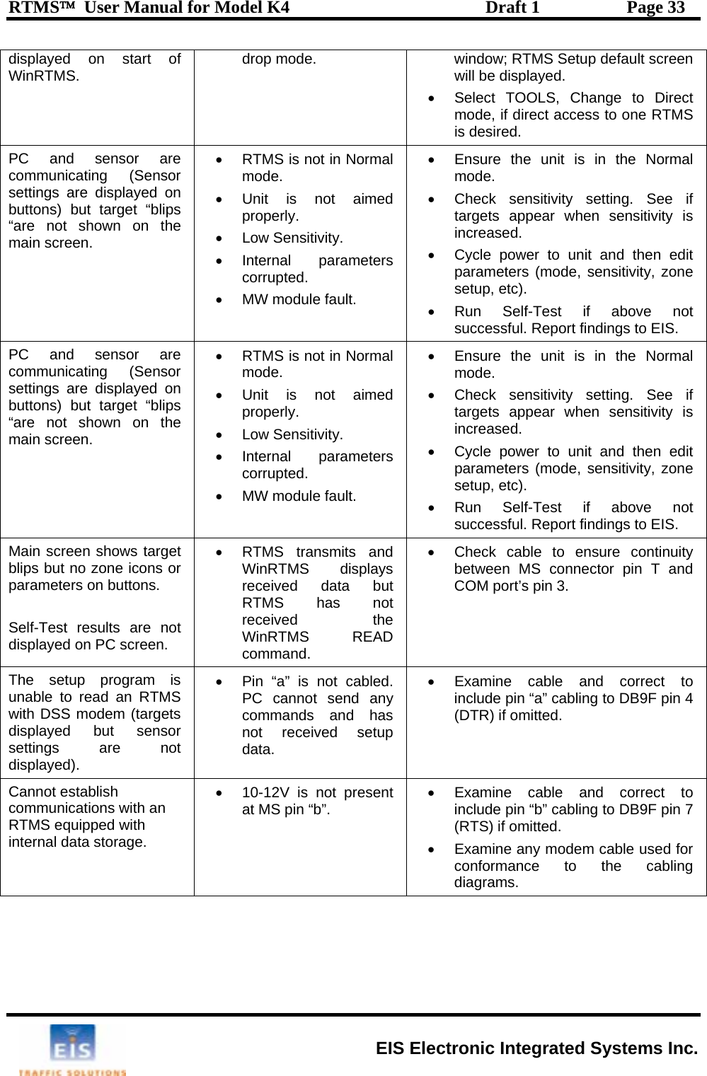
![RTMS™ User Manual for Model K4 Draft 1 Page 29 8 INSTALLATION AND ZONE SETUP - FORWARD LOOKING MODE m interfering structures as shown below. T s ing at receding traffic is preferable. [17 feet] and 6m [20 feet]. the sensor. This will ensure may be mounted on a roadside pole, if the offset (distance from sensor to lane centerline) is less than 3m (10 feet). Extension arms can be used to reduce offset. Forward-looking Mounting and Aiming Sensors are mounted on a sign-bridge or overpass away frohe ensor can be aimed at approaching or receding traffic, aim• Mount the sensor above the center of the lane at a height between 5m• Point it parallel to the monitored lane. • Mount it level side to side. • Looking from behind the unit, aim it to a point about 10m [33 feet] froma sufficiently long footprint but restrict its width to a single lane. • Forward-looking RTMS Figure 16 - Forward Looking mounting options Figure 17 – Queue Detection RTMS can be set up in forward looking mode when serving off-ramp or T-intersection queue applications. In such applications, the RTMS is aimed farther than in the traffic monitoring highway applications. One or more detection zones are defined to span the required distance (within the range limit of the RTMS). The width of the microwave beam may cover two lanes; the sensor cannot discriminate between lanes. EIS Electronic Integrated Systems Inc.](https://usermanual.wiki/Image-Sensing-Systems/RTMS-K4/User-Guide-837554-Page-36.png)
![RTMS™ User Manual for Model K4 Draft 1 Page 30 Zone Setup – Forward-looking Mode When forward looking mode is selected, WinRTMS will psetting the height and offset parameters. resent a window for d menu for changing between metric and A o• n the Zone Setup window. The Wizard will determine the best location for the 3-zone speed trap. If it cannot find a good speed trap due to incorrect RTMS aiming, low volume or other causes, it will display warnings. Manual Zone Setup • Set the number of zones to 8 and position all zones in sequence with the first zone at approximately 8 meters from the sensor (farther if the sensor is higher than 5M). Observe approaching (or receding) vehicles in the lane as "waves" of blips and adjust the tilt and sway angles so that blip waves from small vehicles go through at least 5 of the 8 zones and so that vehicles in adjacent lanes do not show blips in the zones. Detection of vehicles from an adjacent lane indicates that the sensor is angled in that direction or aimed too high. • Set Fine Tune control to +5. • Observe approximately 50 vehicles. Find three consecutive zones, for which vehicle counts are in close agreement with each other. The location of these three zones will form the speed-trap. Note their position on the ra bers 1, 2 and 3 over these three consecutive zone positions, then reduce the total number of zones to 3. • Only Zone #1 is used for volume and occupancy data. Zone #2 and #3 complete the speed trap and help determine the direction of travel. Forward-Looking Speed calibration The RTMS provides Doppler speed measurements and does not need to be calibrated for this, only the Speed Trap length for slow moving traffic needs to be calibrated. Ensure that the main screen box Per Uncheck this box to suppress porting of per vehicle data, if desired, after completion of speed calibration. • Use left/right keys to highlight a parameter and up/down keys to enter the value. Press Enter or click OK to accept the displayed parameters. The length units will be decimeters or feet depending on the units used for reporting speeds. • See Km/h-MPH in the Advanceimperial units. ut matic setup Initiate the automated zone setup either by clicking the Wizard icon or AUTO button onge scale and using ZONES, move zones numVehicle Speed is check-marked. reIn the Forward-Looking Highway mode, the RTMS uses the Doppler speed, as the reference speed to calibrate the speed trap. Speed trap measurements are used when speeds are below 10 MPH [16 km/h] where the Doppler measurement does not function. EIS Electronic Integrated Systems Inc.](https://usermanual.wiki/Image-Sensing-Systems/RTMS-K4/User-Guide-837554-Page-37.png)
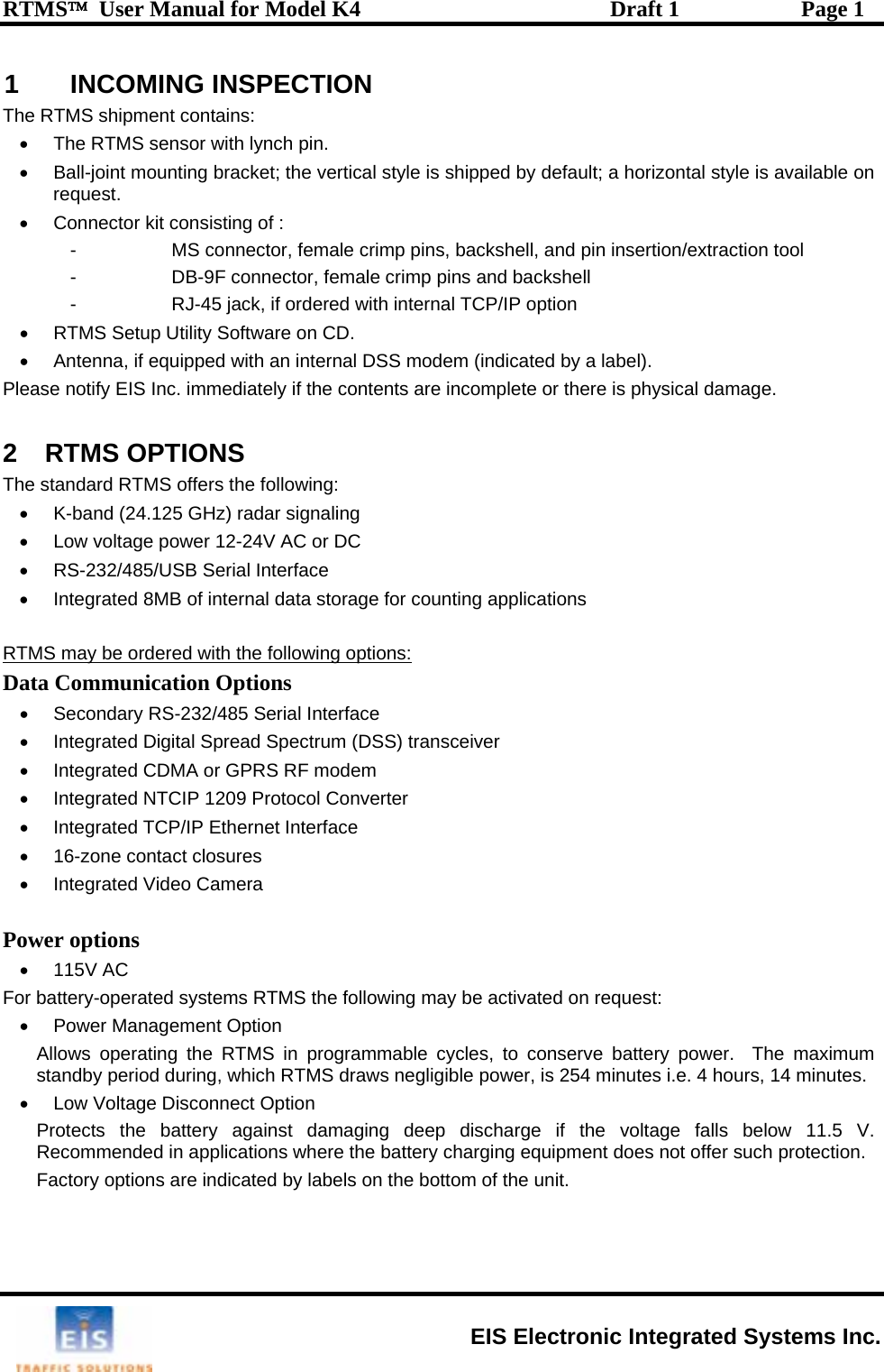
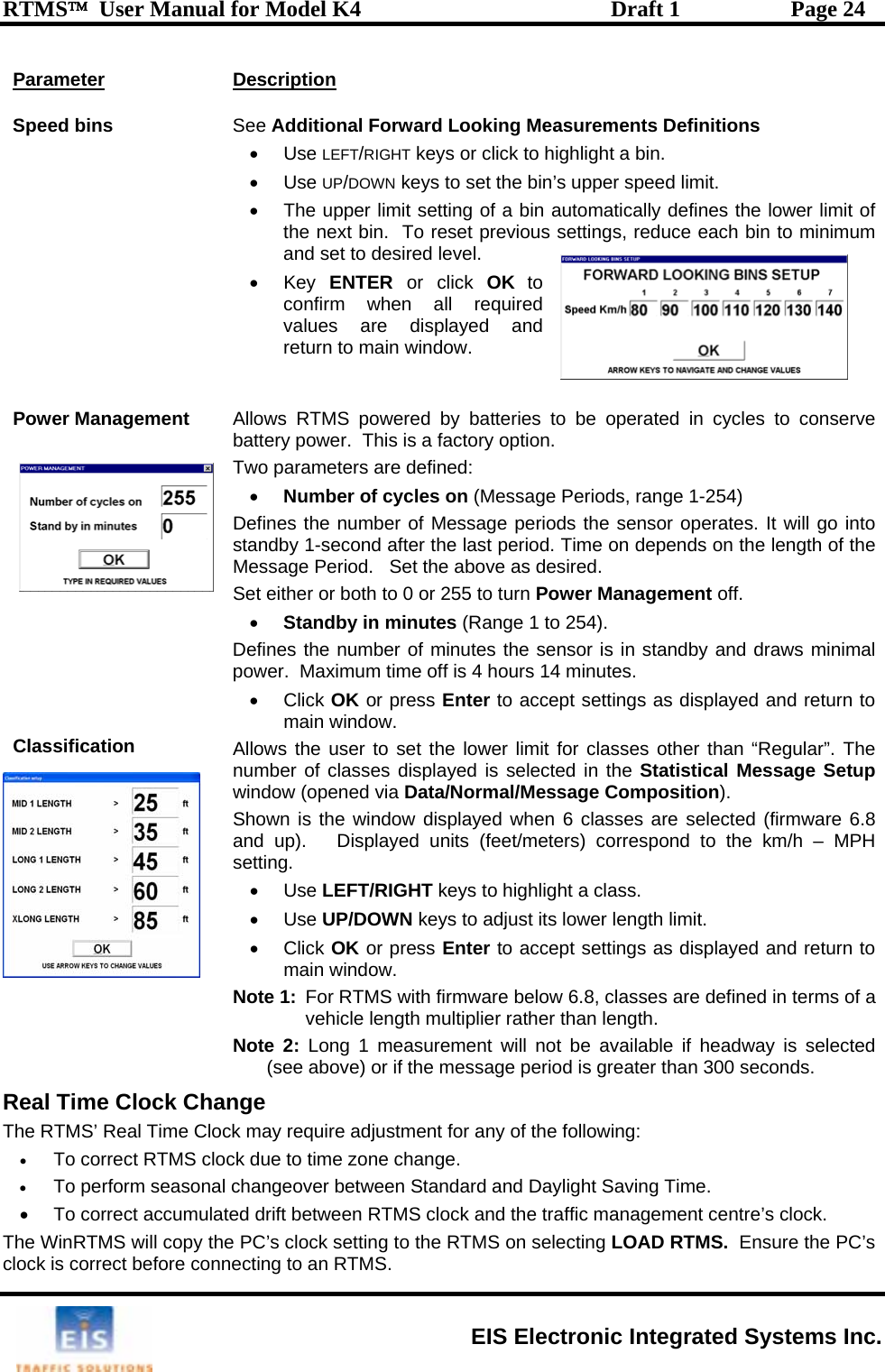
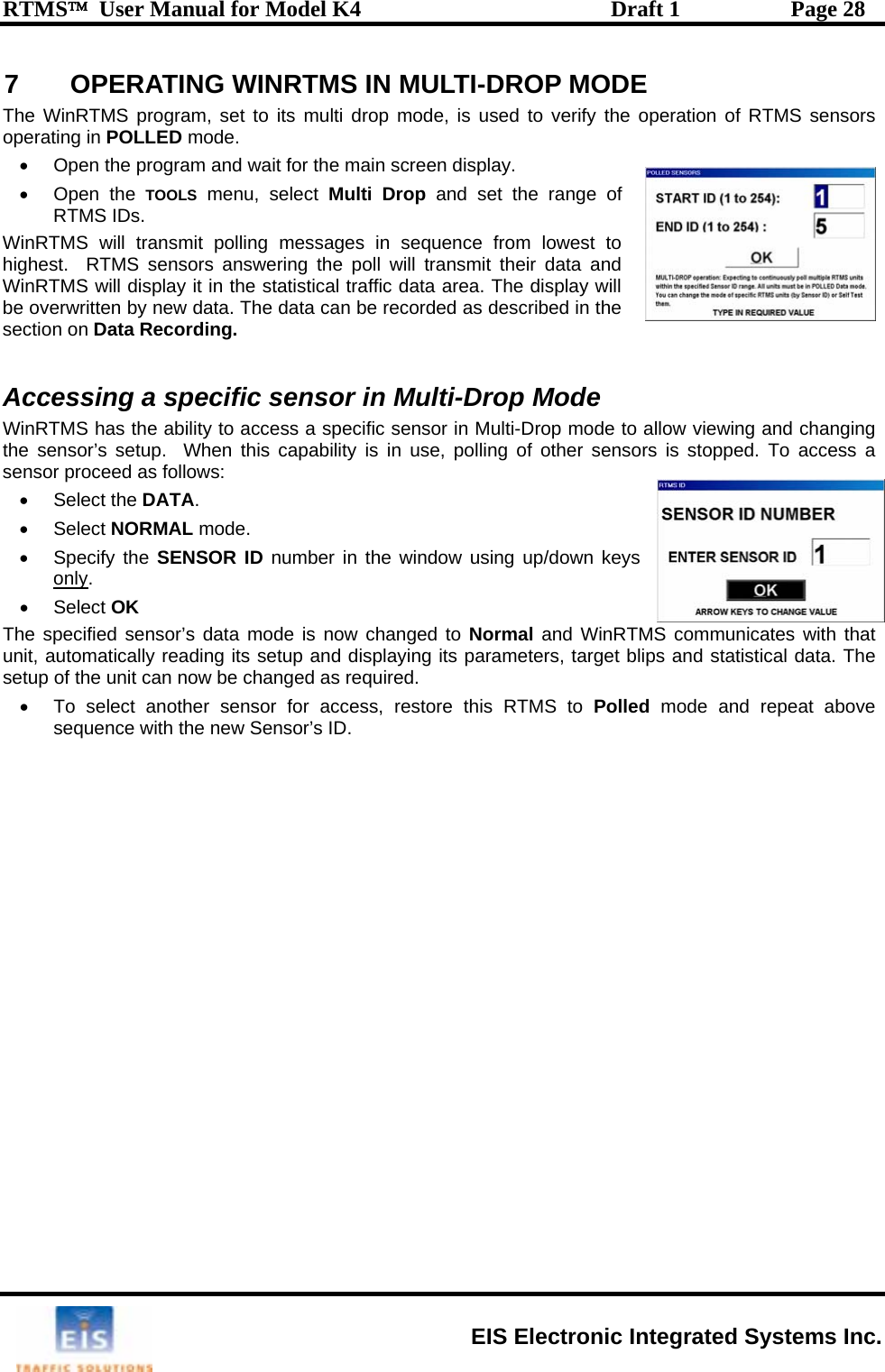
![RTMS™ User Manual for Model K4 Draft 1 Page 36 Power Requirements and Consumption C or DC r 24VAC. ed fusing (external) 2A s um nsumption (Standard Power) 2.7 W of options DSS = 2.0 W, TCP/IP =1.2 W 115±-60Hz, 3W voltage wer dard, additional port Optional justa and 115200 . tance depends on se peed: 200 -1000 ft. •0m (4000 feet). 0 feet. emotely or locally S gThe RTMS withstandal eE • RTMS standard power requirement 12-24V A• Over-voltage shutdown limit 34VD oC• Recommend low blow minim• Automatic recovery from power failure Within 5 seconds, with DSS – 20 seconds • Power co atts • Additional Power consumption• Comm 20V AC @ 50ercial AC power optionInterfaces Zone Contact Ratings• Maximum current 100mA • Maximum 400V • Maximum dissipated po 300mW . Data Ports • USB 2.0 with range up to 30 feet • One isolated port Stan• Ports operating at no parity, 8 bit, 1 stop bit ble speed between 2400 at adbits/sec (bps)• RS-232 operating dis lected s RS-485 option extends range up to 120• Optional Ethernet port with range up to 3Flash Upgrade Available over data port rur e immunity ±s 1kV surge (rise time = 1.2 µsec, hold = 50µsec) applied in differential mode to l lin s, power and output, as defined by IEC 1000-4-5 and EN 61000-4-5 standards. nvironmental Conditions Operating limits Shipping and Storage THumid 5g 10ms half sine wave ph]will not degrade performance tion (rain or snow) • US FCC Rule part 15 ClasThe RTMS is designed for Mean Time Between Failures (MTBF) of in its operating environment of 90000 hours [10 years]. emperature range -37 to +74°C [-35 to 165°F] -40° to 80°C [-40° to 171°F] ity Up to 95% relative humidity Up to 95% relative humidity ion 2g up to 200Hz sinusoidal VibratShock Wind Winds up to 160 km/h [100mPrecipita Up to 100mm/h Electromagnetic Interference RTMS Model K4 is certified to meet s A, Canadian CSA C108.8 M1983 Class A and CE mark requirements. Reliability EIS Electronic Integrated Systems Inc.](https://usermanual.wiki/Image-Sensing-Systems/RTMS-K4/User-Guide-837554-Page-43.png)