Image Sensing Systems RTMS-K4 RTMS K4 User Manual
Image Sensing Systems, Inc. RTMS K4
User Manual
RTMS™ User Manual for Model K4 Draft 1 Page i
IMPORTANT SAFETY INFORMATION
READ ALL INSTRUCTIONS BEFORE USING
HEED ALL WARNINGS IN THESE INSTRUCTIONS
SAVE THESE INSTRUCTIONS FOR FUTURE REFERENCE
WARNING
RTMS units must be installed and adjusted in accordance with the installation
instructions contained in this manual.
Use the RTMS only for its intended purposes as described in this manual.
Changes or modifications not expressly approved by EIS Electronic Integrated
Systems Inc. could void the user's authority to operate the equipment.
NOTE
This equipment has been tested and found to comply with the limits for a Class A
digital device, pursuant to Part 15 of the FCC Rules.
These limits are designed to provide reasonable protection against harmful
interference when the equipment is operated in a commercial environment. This
equipment generates, uses, and can radiate radio frequency energy and, if not
installed and used in accordance with the instruction manual, may cause harmful
interference to radio communications. Operation of this equipment in a
residential area is likely to cause harmful interference in which case the user will
be required to correct the interference at their expense.
Contact EIS
Please contact EIS with any questions or concerns about the RTMS or other EIS
products, toll free at 1-800-668-9385. More information about our complete
product line is available on the web at www.eistraffic.com.
EIS Electronic Integrated Systems Inc.

RTMS™ User Manual for Model K4 Draft 1 Page ii
EIS Electronic Integrated Systems Inc.

RTMS™ User Manual for Model K4 Draft 1 Page iii
Brief Description
The RTMS (Remote Traffic Microwave Sensor) measures the distance to objects in the path of its
microwave beam. This ranging capability allows it to detect moving and stationary vehicles in multiple
detection zones.
The sensor can be mounted on road-side poles and aimed at a right angle to the road; refered to as the
side-fired configuration. A single sensor can monitor traffic in up to 8 lanes. Sensors may also be
mounted on overhead structures to monitor traffic in a single lane; the forward-looking configuration.
The internal processor calculates volume, occupancy and average speed as well as vehicle class by
length in each lane and transmits the information using its data port. Optional contact closure outputs are
also available for for compatibility with loop based systems.
For optimal accuracy, EIS strongly recommends installation of all RTMS and RTMS related
products by personnel trained by EIS.
EIS also strongly recommends surveying of installation sites for all RTMS and RTMS related
products by personnel trained by EIS.
For more information about our installation, surveying, and training programs, contact EIS at
1-800-668-9385.
WARNING: Consult EIS before using the RTMS or other RTMS related products for any
purpose not expressly described in this manual or any of the other RTMS product
manuals. Do not use the RTMS to control or operate a gate opening mechanism.
Use of the RTMS for this, or any other unauthorized purpose, may lead to serious
injury.
Scope of this Document
This user manual provides information on setup, operation and troubleshooting of the RTMS sensor
model K4, and its setup employing the RTMS Setup Utility (WinRTMS) version 3.5. It is backwards
compatible with all previous RTMS versions.
EIS Electronic Integrated Systems Inc.

RTMS™ User Manual for Model K4 Draft 1 Page iv
Revision History
Issue No. Issue date Reason for issue
Draft 1.0 June 2007 Initial Revison based on V6.8 firmware
EIS Electronic Integrated Systems Inc.

RTMS™ User Manual for Model K4 Draft 1 Page v
Table of Content
1 INCOMING INSPECTION................................................................................................. 1
2 RTMS OPTIONS.................................................................................................................. 1
3 RTMS INSTALLATION – SIDE FIRED CONFIGURATION....................................... 2
MOUNTING AND AIMING.............................................................................................................. 2
SETBACK/HEIGHT DIAGRAMS ...................................................................................................... 3
4 CABLING.............................................................................................................................. 4
SURGE SUPPRESSION .................................................................................................................... 4
THE RTMS CABLE ...................................................................................................................... 4
MS Connector pin-out............................................................................................................. 5
Standard RS-232 Port Wiring................................................................................................. 6
The RS-485 Port ..................................................................................................................... 6
The TCP/IP Port with RS-232................................................................................................. 7
The TCP/IP port with RS-485................................................................................................. 7
CONNECTING RTMS TO REMOTE SYSTEMS................................................................................. 8
Modem Cables ........................................................................................................................ 8
Modem Sharing....................................................................................................................... 9
RS-485 Multidrop.................................................................................................................. 10
5 SETUP OF THE RTMS..................................................................................................... 11
THE RTMS SETUP UTILITY (WINRTMS).................................................................................... 11
GETTING STARTED..................................................................................................................... 11
Changing RTMS Setup Utility COM Port and Mode ........................................................... 12
Changing WinRTMS Mode.................................................................................................. 12
Selecting a different COM Port ............................................................................................ 12
Changing Serial Port Speed .................................................................................................. 12
Setting DSS Parameters (if equipped) .................................................................................. 13
IP Address (if equipped) ....................................................................................................... 14
Preparing the PC ................................................................................................................... 14
Programming the RTMS IP address..................................................................................... 14
DETECTION ZONE SETUP............................................................................................................ 15
Automated Detection Zone Setup (Wizard)........................................................................... 15
Manual Zone Setup - Side-Fired........................................................................................... 16
Fine Tune Adjustment........................................................................................................... 16
Manual Fine Tuning.............................................................................................................. 16
Detection Zone Size............................................................................................................... 16
COUNT VERIFICATION ............................................................................................................... 17
SPEED CALIBRATION.................................................................................................................. 17
Side-fired Automatic Speed Calibration............................................................................... 18
Side-fired Manual Speed Calibration.................................................................................... 18
RTMS OPERATING MODES - DETAILS....................................................................................... 19
6 RTMS STATISTICAL TRAFFIC DATA........................................................................ 20
EIS Electronic Integrated Systems Inc.

RTMS™ User Manual for Model K4 Draft 1 Page vi
MESSAGE PERIOD ...................................................................................................................... 20
Vehicle Classification ........................................................................................................... 21
Setting the number of vehicle classes................................................................................... 21
Class Measurements Display................................................................................................ 22
PER VEHICLE SPEED DISPLAY.................................................................................................... 22
ADVANCED PARAMETERS.......................................................................................................... 23
Real Time Clock Change ...................................................................................................... 24
DATA RECORDING ..................................................................................................................... 25
STORAGE AND DOWNLOADING OF TRAFFIC DATA (DATA STORAGE OPTION ONLY).................. 26
DATA MODES ............................................................................................................................ 27
7 OPERATING WINRTMS IN MULTI-DROP MODE ................................................... 28
ACCESSING A SPECIFIC SENSOR IN MULTI-DROP MODE ............................................................. 28
8 INSTALLATION AND ZONE SETUP - FORWARD LOOKING MODE.................. 29
FORWARD-LOOKING MOUNTING AND AIMING........................................................................... 29
ZONE SETUP – FORWARD-LOOKING MODE ................................................................................ 30
Automatic setup..................................................................................................................... 30
Manual Zone Setup ...............................................................................................................30
Forward-Looking Speed calibration ..................................................................................... 30
9 RTMS INSTALLATION FOR STOP BAR DETECTION............................................ 31
Intersection Controller Settings ............................................................................................ 31
10 RTMS TROUBLESHOOTING GUIDE .......................................................................... 32
RTMS SELF TEST ...................................................................................................................... 32
11 WARRANTY AND SERVICE.......................................................................................... 34
EIS WARRANTY......................................................................................................................... 34
SERVICE INFORMATION.............................................................................................................. 34
12 SPECIFICATIONS............................................................................................................. 35
MICROWAVE SIGNAL AND COVERAGE AREA ............................................................................. 35
MEASUREMENTS, THEIR ACCURACIES AND RANGES.................................................................. 35
Accuracy Performance Conditions....................................................................................... 35
MECHANICAL............................................................................................................................. 35
POWER REQUIREMENTS AND CONSUMPTION ............................................................................. 36
INTERFACES ............................................................................................................................... 36
Zone Contact Ratings............................................................................................................36
Data Ports............................................................................................................................. 36
FLASH UPGRADE........................................................................................................................ 36
SURGE IMMUNITY ...................................................................................................................... 36
ENVIRONMENTAL CONDITIONS.................................................................................................. 36
ELECTROMAGNETIC INTERFERENCE........................................................................................... 36
RELIABILITY .............................................................................................................................. 36
APPENDIX 1 RECOMMENDED SURGE PROTECTION............................................... 37
EIS Electronic Integrated Systems Inc.

RTMS™ User Manual for Model K4 Draft 1 Page vii
Table of Figures
Figure 1 – RTMS Aiming............................................................................................................... 2
Figure 2 - Set-back Distance Chart................................................................................................. 3
Figure 3 – Mounting Height Chart.................................................................................................. 3
Figure 4 – MS Connector................................................................................................................ 5
Figure 5 – RS-232 Wiring Diagram................................................................................................6
Figure 6 – RS-485 Wiring Diagram................................................................................................6
Figure 7 – TCP/IP Wiring Diagram................................................................................................7
Figure 8 - TCP/IP with RS-485 Wiring Diagram........................................................................... 7
Figure 9 – RTMS to Modem connections....................................................................................... 8
Figure 10 – Modem sharing Y cables............................................................................................. 9
Figure 11 - RS-485 Multi-drop wiring.......................................................................................... 10
Figure 12 - Changing RTMS Communication.............................................................................. 12
Figure 13 - RTMS Setup Utility main screen............................................................................... 15
Figure 14 - RTMS Utility Verification Screen............................................................................. 22
Figure 15 – Sample RTMS data file ............................................................................................. 25
Figure 16 - Forward Looking mounting options........................................................................... 29
Figure 17 – Queue Detection........................................................................................................ 29
Figure 18 – RTMS Intersection Installation ................................................................................. 31
Figure 19 – Surge Suppression ..................................................................................................... 37
EIS Electronic Integrated Systems Inc.

RTMS™ User Manual for Model K4 Draft 1 Page 1
1 INCOMING INSPECTION
The RTMS shipment contains:
• The RTMS sensor with lynch pin.
• Ball-joint mounting bracket; the vertical style is shipped by default; a horizontal style is available on
request.
• Connector kit consisting of :
- MS connector, female crimp pins, backshell, and pin insertion/extraction tool
- DB-9F connector, female crimp pins and backshell
- RJ-45 jack, if ordered with internal TCP/IP option
• RTMS Setup Utility Software on CD.
• Antenna, if equipped with an internal DSS modem (indicated by a label).
Please notify EIS Inc. immediately if the contents are incomplete or there is physical damage.
2 RTMS OPTIONS
The standard RTMS offers the following:
• K-band (24.125 GHz) radar signaling
• Low voltage power 12-24V AC or DC
• RS-232/485/USB Serial Interface
• Integrated 8MB of internal data storage for counting applications
RTMS may be ordered with the following options:
Data Communication Options
• Secondary RS-232/485 Serial Interface
• Integrated Digital Spread Spectrum (DSS) transceiver
• Integrated CDMA or GPRS RF modem
• Integrated NTCIP 1209 Protocol Converter
• Integrated TCP/IP Ethernet Interface
• 16-zone contact closures
• Integrated Video Camera
Power options
• 115V AC
For battery-operated systems RTMS the following may be activated on request:
• Power Management Option
Allows operating the RTMS in programmable cycles, to conserve battery power. The maximum
standby period during, which RTMS draws negligible power, is 254 minutes i.e. 4 hours, 14 minutes.
• Low Voltage Disconnect Option
Protects the battery against damaging deep discharge if the voltage falls below 11.5 V.
Recommended in applications where the battery charging equipment does not offer such protection.
Factory options are indicated by labels on the bottom of the unit.
EIS Electronic Integrated Systems Inc.
RTMS™ User Manual for Model K4 Draft 1 Page 2
3 RTMS INSTALLATION – SIDE FIRED CONFIGURATION
Mounting and Aiming
The distance between the close edge of the first lane of traffic to be monitored and the front of the
structure on which the RTMS is mounted is referred to as set-back; it is the most important parameter in
the setup and installation of an RTMS. Generally the more set-back that can be obtained, the easier the
calibration will be.
Use the diagram in Figure 2 to determine the setback required to monitor a given number of lanes. Once
the set-back is set, the associated height can be determined. Height is with reference to the road surface
of the detection area; not the bottom of the mounting pole.
Example: For 5 lanes the minimum set-back should be 12 feet [3.7m].
A set-back of 12 feet [3.7m], requires a height of 17 feet [5.2m].
Note: It is better to be 20 feet [6 m] further back from the minimum than 2 inches [5 cm]
closer than the minimum. If ground conditions allow, move the RTMS further back.
The mounting height is based on the setback. Height is selected to allow the RTMS to be aimed so that
it gets maximum return signal while covering all required lanes. Mounting an RTMS at a height different
from the recommended height will not improve accuracy.
Equivalent lanes include median strips, as an example, an eight lane road with a two lane wide median
strip has 10 equivalent lanes.
•
Boresight
line
Figure 1 – RTMS Aiming
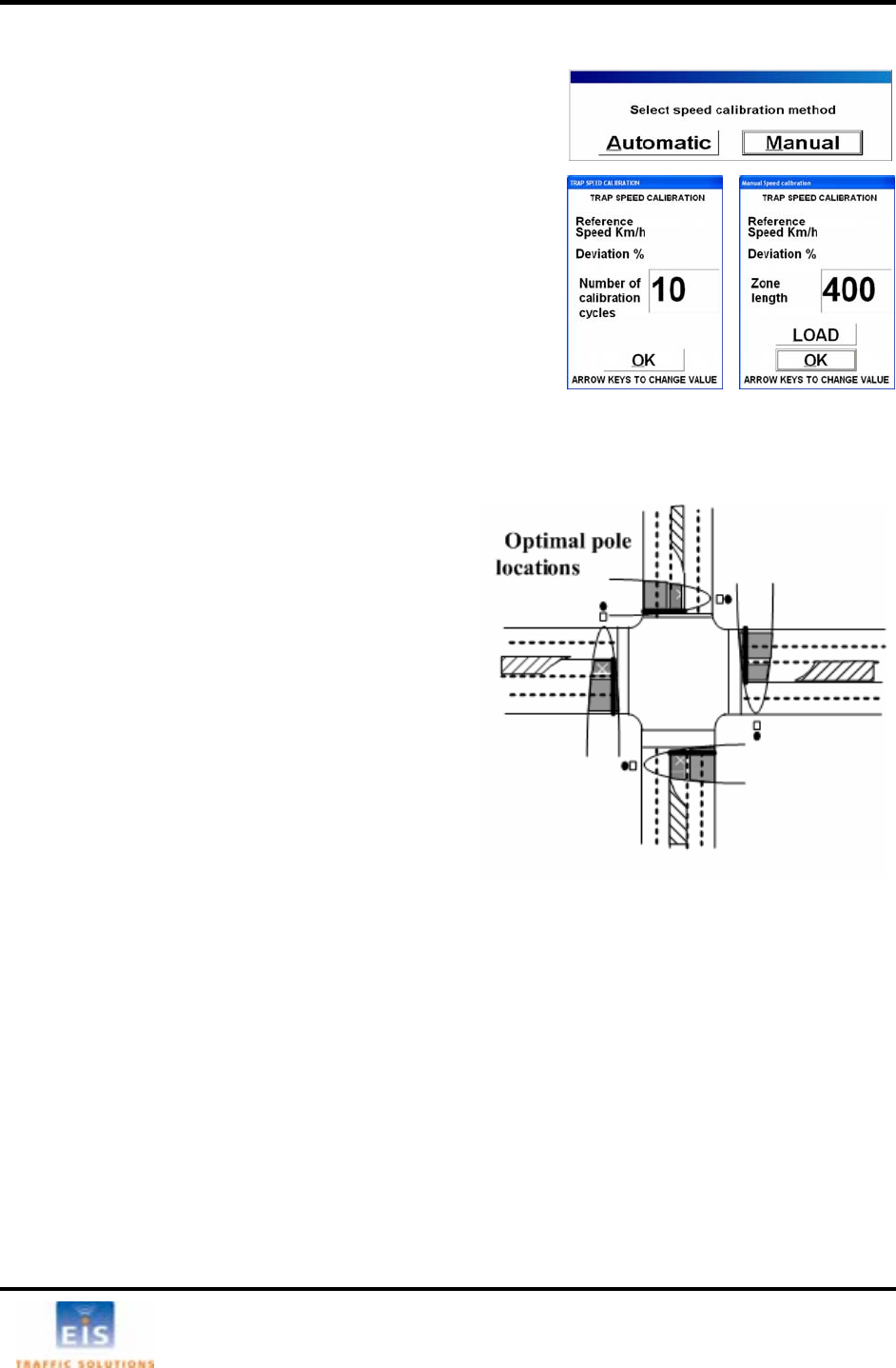
• Attach the RTMS to the roadside pole using bolts or stainless steel banding.
• Aim the RTMS as indicated on the diagram above. A 7/16” wrench is required to release/tighten
the ball-joint bolt.
- Secure the RTMS to the mounting bracket by inserting the lynch pin
- Adjust the RTMS to be perpendicular to the travel lanes.
- Look from behind the unit and use the top aiming fin to tilt so that the top of the RTMS is aimed
to the first 1/3 of the monitored lanes.
- Keep the RTMS level, side to side.
- Lock the aim by tightening the ball-joint bolt.
EIS Electronic Integrated Systems Inc.
RTMS™ User Manual for Model K4 Draft 1 Page 3
Setback/Height diagrams
Figure 2 - Set-back Distance Chart
Equivalent lane calculation is measured from edge of first lane of detection to outside edge of the last
lane of detection and dividing this number by the average lane width. 12 feet is considered typical lane
width.
Example: total detection area = 120 feet; lane = 12 feet; 120/12 = 10 equivalent lanes
Figure 3 – Mounting Height Chart
If more room is available increase the setback as much as possible; then obtain the proper mounting
height based upon actual set-back distance.
EIS Electronic Integrated Systems Inc.

RTMS™ User Manual for Model K4 Draft 1 Page 4
4 CABLING
Surge suppression
Although the RTMS has built-in surge suppression, it is strongly recommended that external surge
suppression be installed with every detector. In situations where long cable runs are utilized, the
communication and power lines of the RTMS should be equipped with external surge protecting devices
on the same pole as the detector. The suppression devices should be located close to the sensor; e.g.
in a cabling cabinets mounted on the pole below the RTMS. See Appendix 1 for further details on
installing surge suppression.
The RTMS Cable
RTMS units use a single 32-pin MS connector for power and communications. The RTMS ships with all
required connectors, crimp pins and back-shells.
The RTMS cable should be made from 20 or 22 gauge stranded wire arranged in pairs. Cables that will
be exposed to outdoor conditions should be UV shielded. The number of pairs required depends on the
communication options chosen:
Table 1 – Cable pairs required
Communication Options # of Pairs
Standard RS232 or RS485 plus power 4
Standard RS232 plus power and Internal RF modem option 4
TCP/IP and RS232 or RS485, plus 6 power
Zone contact option can be added to any of the above 1 per zone (max 8)
A cable such as the Belden number 95xx (xx indicates number of pairs, i.e. 9516 is a 6-pair cable) or
In preparing a cable note the following:
• The crimp pins are designed for stranded wire. Do not use cable employing solid wires
similar should be used.
.
• EIS suggests the Daniels Manufacturing Corporation crimping tool M22520/1-01 AF8 with head
no. M22520/1-02 or equivalent. Do not solder crimp pins!
• Thread cable through the backshell before inserting pins into shell.
• Use the insertion tool (red) to insert wires with crimped pin into shell.
• Use the extraction tool (white) to remove a crimped wire to correct an error.
• It is recommended to use a cable with at least one spare pairs of wires for future growth.
Consideration needs to be made with regards to placement of an access point within view of the
monitored lanes, as an example, an access panel or cabinet on the pole. This allows verification of the
sensors calibration to be easily be done by seeing the RTMS data together with the actual roadway data.
EIS Electronic Integrated Systems Inc.

RTMS™ User Manual for Model K4 Draft 1 Page 5
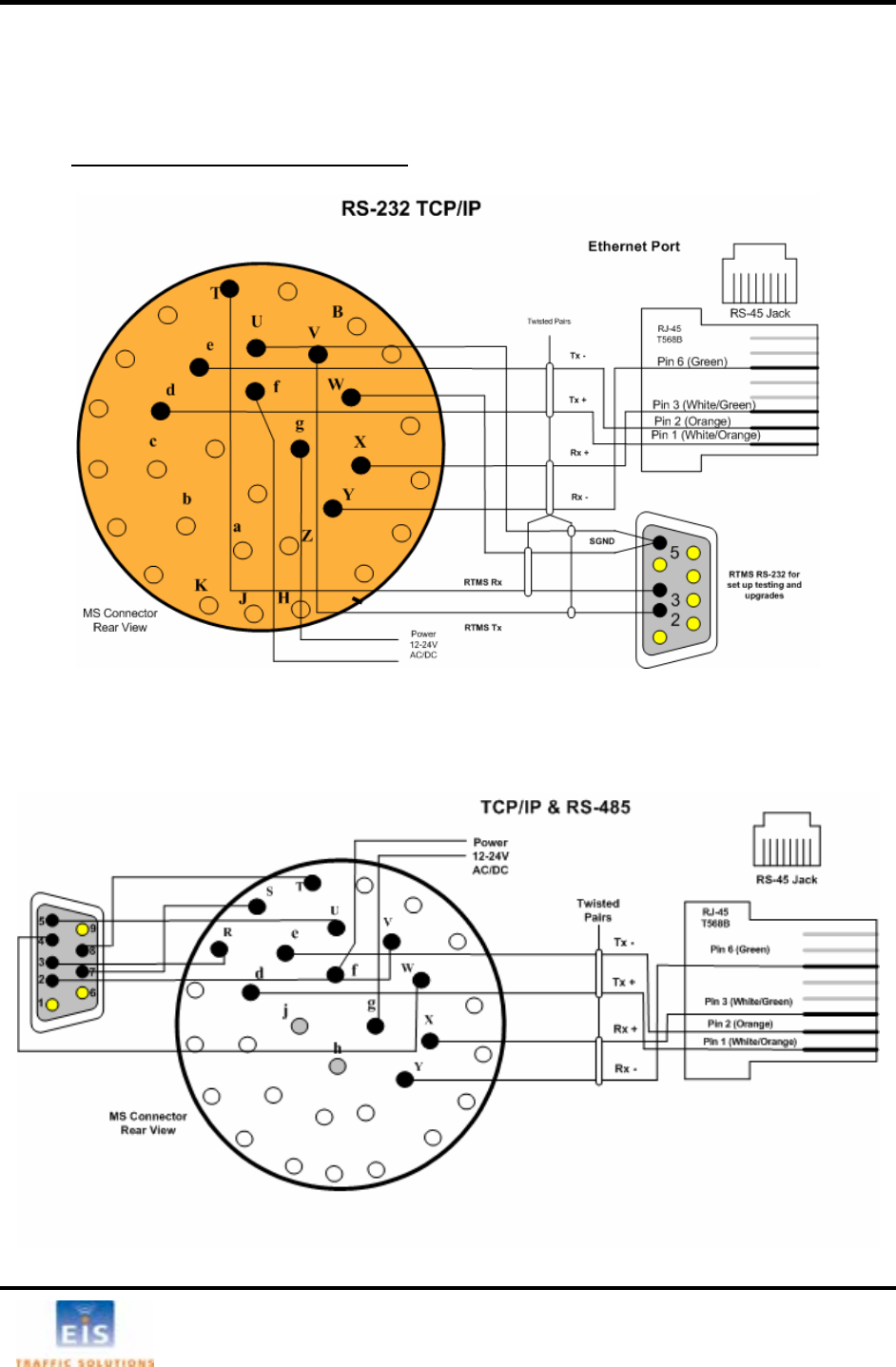
MS Connector pin-out
Table 3 – MS Connector Pin Outs
Pin # Function Pin # Function
A, B Zone #1 U, W Serial Port Signal Ground
C, D Zone #2 X RS-485 Tx + or Ethernet Rx + or RTS
E, F Zone #3 Y RS-485 Rx + or Ethernet Rx – or CTS
G, H Zone #4 Z Unused
J, K Zone #5 a USB D+
L, M Zone #6 b USB VBUS
N, P Zone #7 c USB D-
R Zone #8 d Ethernet Tx +
S Zone #8 e Ethernet Tx -
T Serial Port Input to RTMS
RS-232 Rx or
f, g Low Voltage power 12-24V AC or DC
RS-485 Rx -
V Serial Port Output from RTMS h, j 115V AC power
RS-232 Tx or RS-485 Tx -
Figure 4 – MS Connector
Note: Pin labeling above is guideline only – verify pin location on actual connector before inserting wire
WARNING – The RTMS unit can be configured for a variety of communication
options. It is important to know which options are included with your unit
prior to preparing cables. MS connector pins cannot be shared.
Take note of the individual wirin
g
instructions
p
rovided in this manual.
EIS Electronic Integrated Systems Inc.
RTMS™ User Manual for Model K4 Draft 1 Page 6
Standard RS-232 Port Wiring
wiring consists of Transmit (Tx), Receive (Rx) and Ground lines wired
pins /W respectively. The u fe ctor and wiring shown allows the use
ndard le for direct connection C ews of connectors are
n to assist in cable preparation. The R co Figure 5 outlines the
g req
The standard RTMS RS-232 port
to MS V, T and U se of a male conne
of sta
show serial cab to the P
TMS is for setup purposes. Rear vi
nfigured as a DCE device.
cablin uirement.
Figure 5 – RS-232 Wiring Diagram
The RS-485 Port
Over short distances the wiring diagram shown below is compatible with an RS-232 port. There is no
standard pin configuration for RS-485 on a DB9 connector. The wiring diagram shown will connect
directly to a RS-232 configured DB9 without the need for a RS-232/RS-485 converter.
A demarcation point is recommended to allow the RTMS to be disconnected from the transmission line
without disruption of communications with other sensors on the line. See Connecting RTMS to
Communication Systems for details.
Figure 6 - RS-485 Wiring Diagram
EIS Electronic Integrated Systems Inc.
RTMS™ User Manual for Model K4 Draft 1 Page 7
The TCP/IP Port with RS-232
CAT5 cable must be used for lengths between 30 ft [10m] and 330 ft [100m]. Lengths greater than 330
feet are not supported for Ethernet communication.
It is recommended that both TCP/IP and RS-232 ports be brought out to their respective connectors, as
shown. Only one port may be in use at a time. The RS-232 port is useful for setup and maintenance
purposes.
Figure 7 - TCP/IP Wiring Diagram
Note: There are no extra cabling requirements when Internal Memory is installed with a unit
communicating over TCP/IP.
The TCP/IP port with RS-485
Figure 8 - TCP/IP with RS-485 Wiring Diagram
EIS Electronic Integrated Systems Inc.
RTMS™ User Manual for Model K4 Draft 1 Page 8
Connecting RTMS to Remote Systems
RTMS may be connected to a remote traffic data collection system over private telephone lines using
modems.
Multiple RTMS units connecting to remote systems, including EIS Cluster or NEWS systems must be
placed in their Polled mode and will require the use of modems.
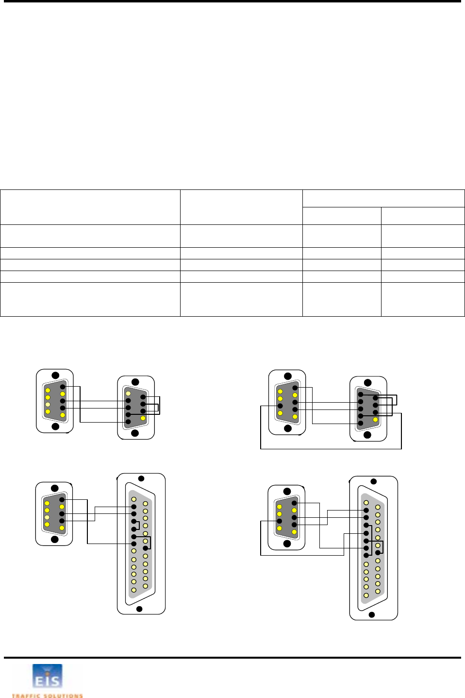
Modem Cables
A cable connecting the RTMS RS-232 port to the modem’s RS-232 port must provide the following:
• male connectors at both ends
• provide the functions listed below
A modem’s RS-232 ports will usually employ DB9 or DB25 connectors.
Table 4 – Modem Cabling
To Modem
Function From RTMS DB9
DB9 DB25
Transpose Tx and Rx Pin 2
Pin 3 Pin 3
Pin 2 Pin 2
Pin 3
Connect Ground Pin 5 Pin 5 Pin 7
CTS to RTMS (Internal storage only) Pin 7 Pin 8 Pin 5
Modem side control line looping
CTS to RTS (Standard RTMS)
DCD to RTS (Internal storage option)
DSR to DTR
Pin 8 to Pin 7
Pin 1 to Pin 7
Pin 6 to Pin 4
Pin 5 to Pin 4
Pin 8 to Pin 4
Pin 6 to Pin 20
Standard RTMS RTMS with Internal Data Storage Option
2
3
95
6
2
3
6
59
7
8
13
7
8
6
5
4
3
214
20
25
1
2
3
5
6
9
DB-9 Male
Rear View
DB-9 Male DB-9 Male
Modem side
DB-25 Male
Rear View
Rear View Rear View
1
RTMS side
2
3
5
6
92
3
5
6
9
7
8
13
7
8
6
5
4
3
214
20
25
1
2
3
5
6
9
DB-9 Male
Rear View
DB-9 Male
Rear View DB-9 Male
Rear View
Modem side
DB-25 Male
Rear View
1
RTMS side
ns Figure 9 – RTMS to Modem connectio
EIS Electronic Integrated Systems Inc.
RTMS™ User Manual for Model K4 Draft 1 Page 9
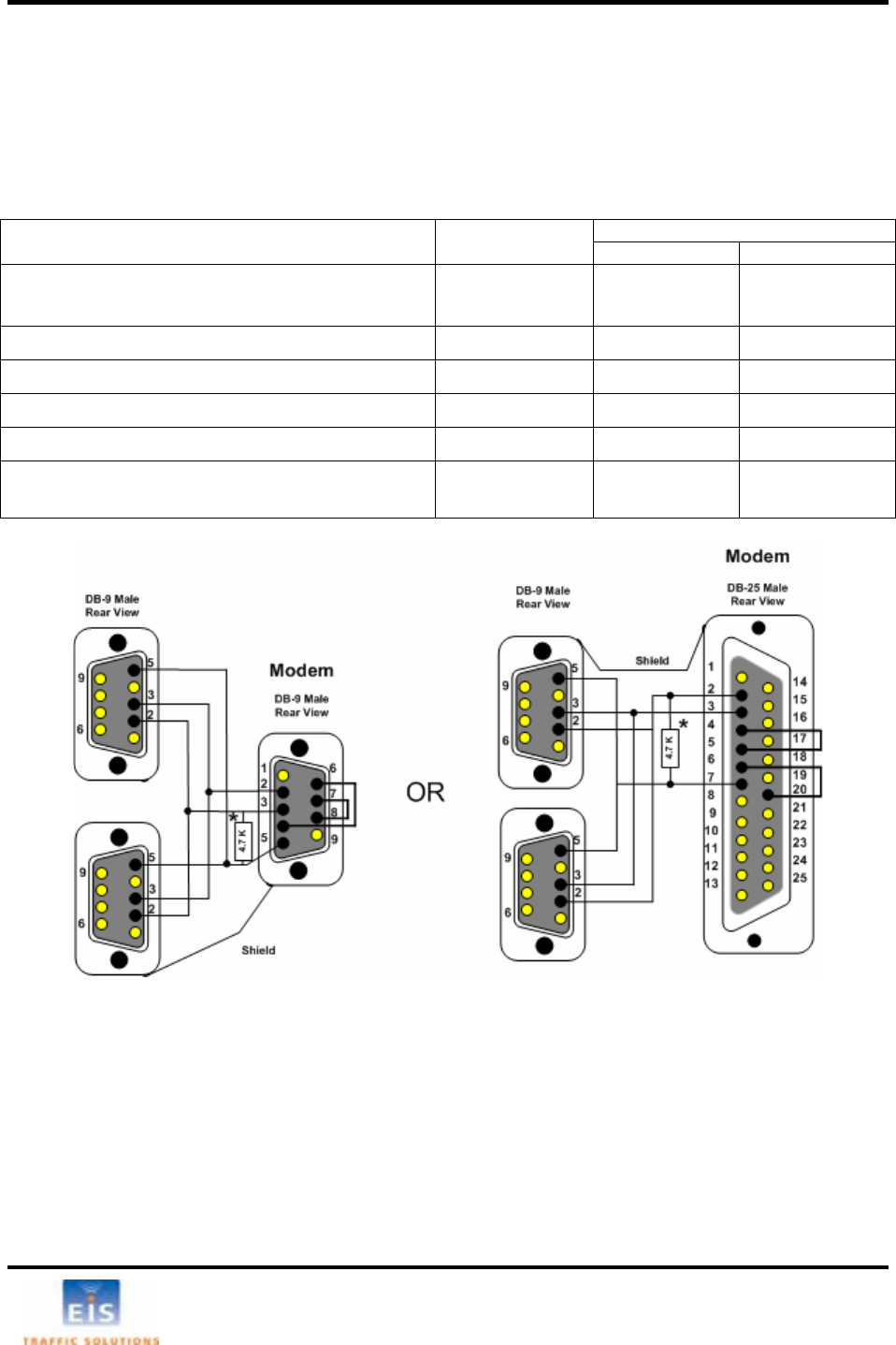
Modem Sharing
gle modem. A modem sharing cable will have RTMS units located in close proximity may connect to a sin
“Y”- construction and will consist of one DB-9M connector per RTMS and one DB-9M or DB-25M
connector at the modem, as shown below:
Modem side strapping provides required flow control functions, not provided by the standard RTMS RS-
232 port.
To modem Connection Function From RTMS
DB9M DB9M DB25M
Trans Pins 2
Pins 3 Pin 3
Pin 2 Pin 2
Pin 3
pose Tx and Rx
Connect Signal Ground Pins 5 Pin 5 Pin 7
Modem side s
trapping
Strap RTS to CTS Pin 7 to Pin 8 Pin 4 to Pin 5
Strap DTR to DSR to Pin 6 to Pin 20 Pin 4 Pin 6
Connect a 4.7KΩ resistor from Tx to gr o to Pin 5 to Pin 7
ound t
prevent noise
Pin 3 Pin 2
Figure 10 – Modem sharing Y cables
EIS Electronic Integrated Systems Inc.
RTMS™ User Manual for Model K4 Draft 1 Page 10
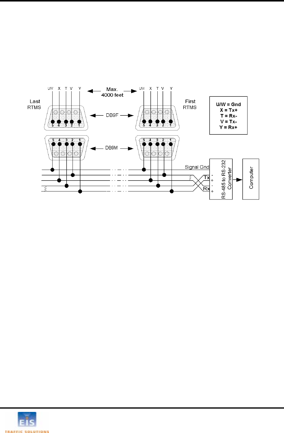
RS-485 Multidrop
ject.
The RS-485 Serial Port option may be employed for distances up to 4000 feet (1200m). The maximum
number of units per channel is 32.
The diagram below shows the use of a 4-Wire line. The use of a half-duplex 2-Wire line is feasible but it
is suitable for data collection only. Consult RS-485/422 Application Guides for details on wiring solutions
for your pro
Figure 11 - RS-485 Multi-drop wiring
Notes:
1. The DB9 connectors and terminal blocks serve as a demarcation point, which allows unplugging the
RTMS from the transmission line for direct connection to the laptop’s COM port for setup.
2. Terminating resistors (100-120 ohms) are required at the extreme ends of the Receive and Transmit
transmission pairs.
3. Transmit and receive pairs must be transposed when connecting to a DTE (PC, Data processing
System). To interface with a PC a RS-485/232 converter may be required as PCs typically do not
have RS-485 interfaces
4. RS-485/232 converter connector type and pin assignment are not shown as these are not
standardized and vary between models.
EIS Electronic Integrated Systems Inc.
RTMS™ User Manual for Model K4 Draft 1 Page 11
5 SETUP OF THE RTMS
he RTMS Setup Utility (WinRtms)
he WinRTMS is supplied as a self installing program “WinRTMSInst.exe”. The installer will create a
lder in C:Program Files\EIS\WinRTMSV#’ with the WinRTMS.exe executable program, auxiliary files
and a shortcut on the desktop.
The WinRTMS program has two operating modes, Direct and Multidrop. In Direct mode it
communicates with a single RTMS. Multidrop mode is used to communicate with multiple RTMS on a
single communications channel.
The WinRTMS buttons and menus may be operated by any of the three methods listed below. The terms
select/click will be used throughout this manual to describe any of these methods
• by mouse
• by up/down/left/right keys followed by ENTER
• by keyboard shortcut (keying the underlined letter)
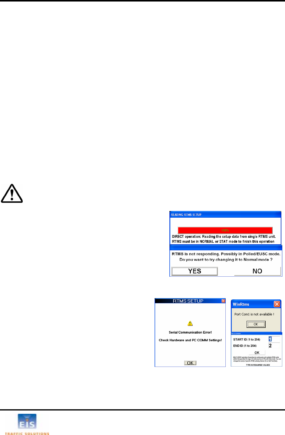
Getting Started
Once installed, RTMS sensors must be calibrated using the RTMS Setup Utility program running on a
Microsoft Windows based PC. The PC will require a USB, serial or Ethernet port to communicate with
the RTMS.
T
T
fo
DO NOT connect the RTMS to the COM port before the PC has been powered and
Windows is running! Windows may disable the COM port if it detects activity during
the boot process.
• With the RTMS sensor pow
, click the WinRtms.exe icon to launch the RTMS
tup Utility program.
suggesting corrective action will be
• its setup.
Com e:
• RTMS is not powered
• No connection to the PC’s COM Port (e.g.
cable not plugged in or is faulty, etc)
• Wrong COM port selected
• Communication of RTMS is IP
• Tx & Rx lines are crossed
• COM port is being used by another
program
See the Troubleshooting Guide for additional suggestions on diagnosis.
If the default COM1 port is used by another application, the information window on the right will be
displayed. If the WinRTMS program has been set to Multi-drop mode, the window with the sensor ID
range will be displayed.
• In either case, click OK to display the default window
ered and connected to the
PC
Se
• While reading the RTMS’ parameters, WinRTMS
displays the READING RTMS SETUP information window. If
unable to establish communications within a timeout
period; dialog boxes
displayed.
Select YES to send corrective commands to the RTMS
and re-attempt reading
If communication is still not established, a default main window will be displayed with “Serial
munication Error!”. Possible reasons ar
EIS Electronic Integrated Systems Inc.
RTMS™ User Manual for Model K4 Draft 1 Page 12
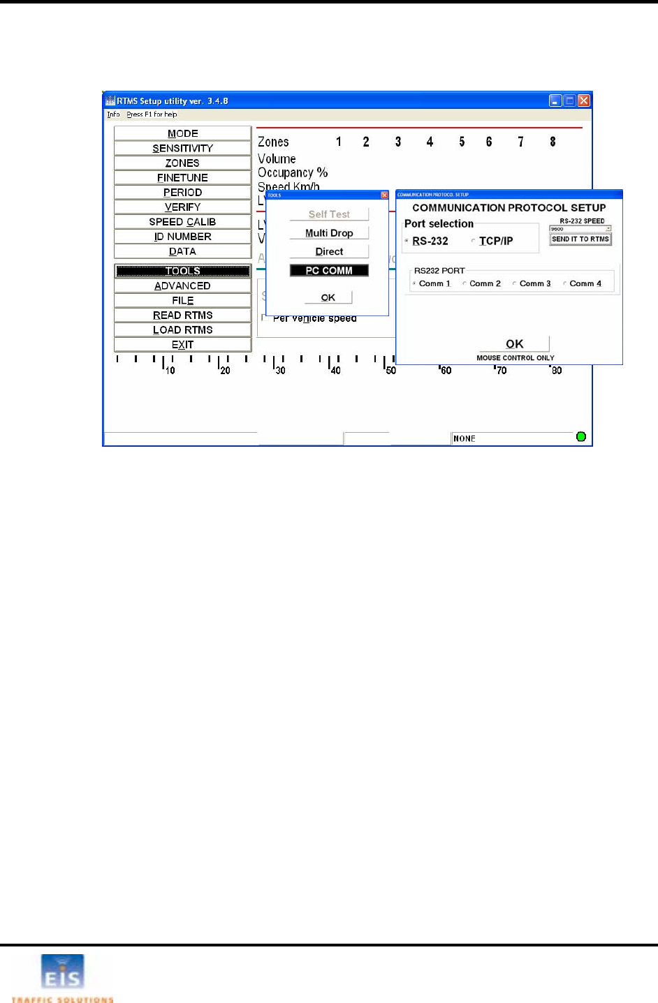
Changing RTMS Setup Utility COM Port and Mode
Changing RTMS Communication
C n
•
•
Se
• OLS and PC COMM
in the
at the b m shes. The RTMS is now ready to be calibrated.
Changi g
Default com its per second (bps) for serial units, and 19200 bps for Ethernet
based units ); other speeds can be selected from the drop down menu if
required ve the communications rate fixed at 115200 bps.
• O n MUNICATION PROTOCOL SETUP window
• S
.
Figure 12 -
ha ging WinRTMS Mode
Select TOOLS
• Select Direct or Multi Drop, as applicable
Click OK
lecting a different COM Port
Select TO
• Select a different COM Port in the COMMUNICATION PROTOCOL SETUP window
• Click OK
Once communication with the RTMS is established and the sensor has responded to the READ
comma t s are displayednd, he current RTMS setting
otto right of the window fla menu button column and the COMM indicator
n Serial Port Speed
munication speed is 9600 b
(internal serial to IP connection
. RTMS with internal DSS radios ha
pe TOOLS - PCCOMM - COM
elect another speed from the pull-down menu
• Click SEND IT TO RTMS
Data rates below 9600 are useful where high quality transmission lines are not available. They are
however, unsuitable for setup and must be selected after setup has been completed. When using data
rates below 9600 bps, the RTMS data mode must be set to STAT to reduce the amount of data and
prevent communication problems. See DATA MODE for further details
EIS Electronic Integrated Systems Inc.
RTMS™ User Manual for Model K4 Draft 1 Page 13
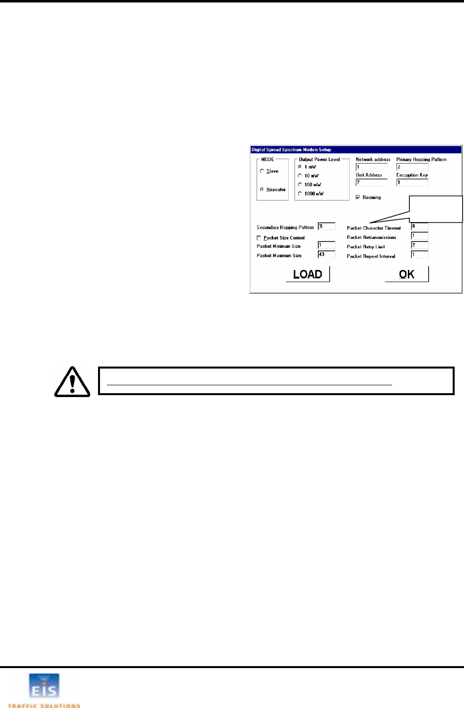
Setting DSS Parameters (if equipped)
eed is not selectable. DSS units will
display a DSS box at the bottom right of the WinRTMS window; this box will display green if a connection
is present with the master radio, if no connection is available, the box will display red. A DSS button also
appears in the Communication Protocol Setup Window.
RTMS DSS units are shipped with all of the basic radio parameters set to 1, unless other arrangements
have been made with EIS. These parameters must be changed to match those of the master radio
modem that the units will be communicating with.
Proceed as follows:
• Select TOOLS then PC COMM
• Click DSS Modem button.
The Digital Spread Spectrum Modem Setup window
will open.
• Ensure that the settings are as follows:
Mode = Slave For simple line of sight
communication
or
Mode = Repeater Where the RTMS DSS
relays data from other
DSS modems and acts as
a master for these
modems.
Roaming =Always on. This feature allows slaves or repeaters to locate a master by the network
address an ping pattern.
• Enter the Master’s Net
ameter must be unique for each slave.
RTMS DSS units are set to communicate at 115200 bps; the sp
d encryption key and adopt its primary hop
work, Address, and Encryption codes.
• Enter Unit Address: This par
Additional
Fields
• Output Power Level – is determined based upon the Radio Site Survey. Strength of signal is
If power setting is too high it may interfere with other radio
the data messages may be missed.
D to send displayed settings
the same type and
the same order will be of the same type and frequency. Refer to
d instructions for setup of the master DSS parameters.
important to ensure data quality.
w systems in the area, if it is too lo
• Enter the additional parameters if the DSS is set as a repeater.
to the RTMS. • Click LOA
• Click OK to exit without change.
The DSS box will turn green when communication with a master modem is established.
The master DSS communicating with the RTMS slave or repeater must be of
frequency band. All units supplied on
the manufacturers’ documentation an
It is mandatory to make Unit Address = RTMS Sensor ID.
EIS Electronic Integrated Systems Inc.
RTMS™ User Manual for Model K4 Draft 1 Page 14
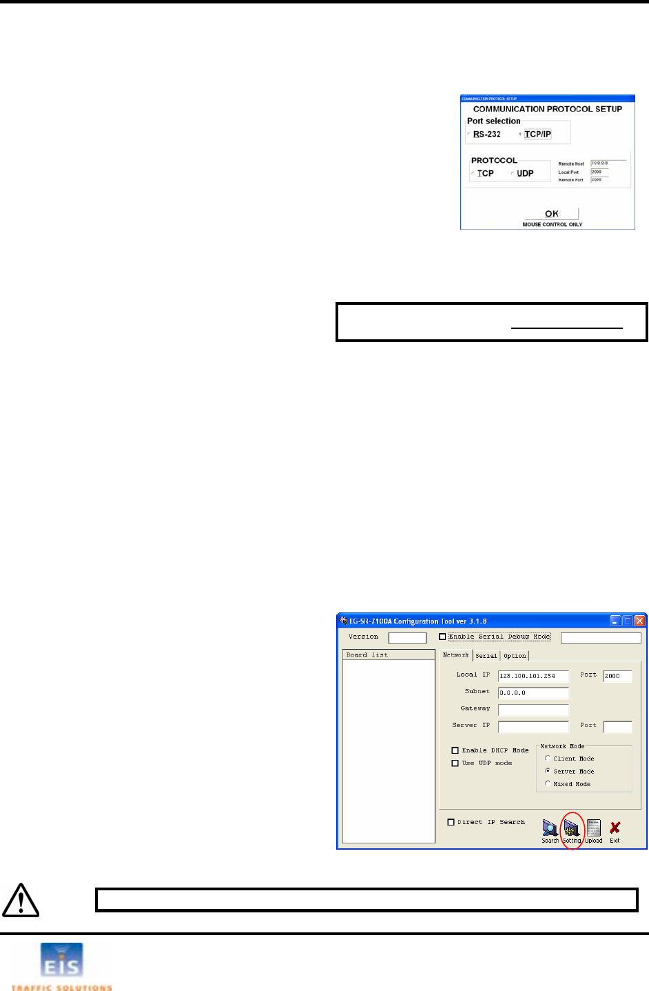
IP Address (if equipped)
For ease of setup/maintenance, it is suggested to wire of the RS-232 interface as recommended in
Section 4 – RTMS Cable-TCP/IP. WinRTMS may be used to communicate with an RTMS via the
Internet to view/change its setup. Proceed as follows:
• Select Tools/PC Comm/Communication Protocol Setup
rt=2000.
ady to establi
r RTMS, repeat the above process and enter a
ress.
T in default TCP/IP address of 128.100.101.254
to change .
paring the PC
static IP teps (assumes Windows XP Operating System)
• Access the Control Pa ions.
• Right-click Local Area
• From the list of installe n Internet Protocol (TCP/IP).
d s
• Enter 128.100.101.1 a
P g
ndicator lights should light.
Use a crossover c
• Open the sup d
After
displa ings of the board.
• Use UDP mode = disabled
• Direct IP search = disabled
• Enter new IP address
• Edit Port #, and subnet, if applicable
• Leave all other areas unedited
• Click Setting to save and Exit to close program
• Click
TCP/IP
• Enter the RTMS IP address in Remote Host box
TCP, Local Port=2000 and Remote Po
• Set Protocol =
• Click OK to close the window
The WinRTMS stores the entered IP address in its internal files, re
IP address on subsequent opening. To access anothe
new IP add
sh a link with the stored
he ternal RTMS IP server is programmed with a . Use the
procedure below it to the required address
Pre
Configure the PC for operation in the following s
nel. Open Network Connect
Connections and open Properties.
d network components select and ope
Default IP address is 128.100.101.254
• Click Properties an elect Use Following IP Address.
nd Subnet = 255.255.0.0. Click OK and Close.
ro ramming the RTMS IP address
• Connect RTMS to the PC. The PC’s Network Port Link and Activity i
able if communication was not established
EG-SR-7100A Configuration Tool program plie
• With the Network tab open, click Search.
communication with the internal EG-SR-7100A Gateway Module is established, the program will
y the MAC address of the unit in the Board list area and the default sett
• Local IP = 128.100.101.254
• Port = 2000
• Subnet = 0.0.0.0
• Gateway = blank
• Server IP & Port = blank
• Network Mode = Server Mode
• Enable DHCP mode = disabled
WARNING: DO NOT open and make changes to settings under the Serial tab
EIS Electronic Integrated Systems Inc.
RTMS™ User Manual for Model K4 Draft 1 Page 15
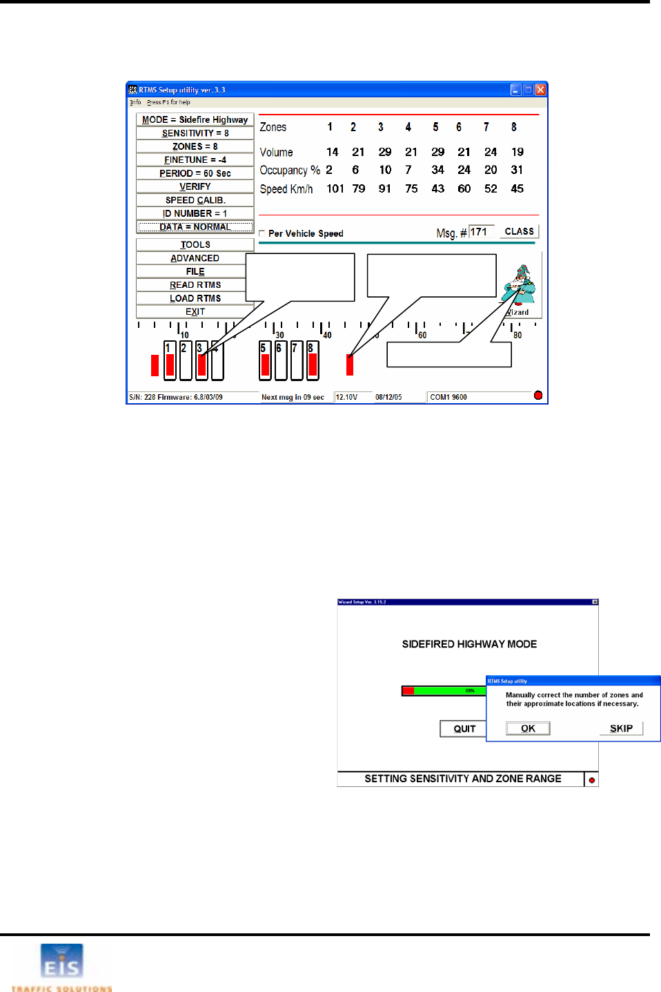
Detection Zone setup
The RTMS Setup Utility shows the position of vehicles by the red target “blips” against the distance scale
Figure 13 - RTMS Setup Utility main screen
U o icons where the target blips
are seen. Th ent in the detection zones.
A o
Th a lanes of interest. It scans the range
of e icles are detected. The
pr rs.
la s t. Adjust
• C zard icon.
• S
The Wizard eed to
position e ehicles are
detecte
The pro ss mb rs
with Zo 1 c sulting
zone se
• C ceptable
to select fewer zones, exclude ramps, etc.
A the Wizard will continue the automatic setup with Fine Tune
a g Quit. On completion, control will return
to the main windo
p t 8 detection zones may be defined by positioning the rectangular zone
e zone’s contact closure circuit is closed while vehicles are pres
ut mated Detection Zone Setup (Wizard)
utomated zone setup process requires free flowing traffic in ae ll
th RTMS microwave beam and positions up to 8 detection zones where veh
ocess differentiates between vehicles and barrie
Proceed as follows:
• Verify that target blips are observed in all
ne of interes aiming if necessary.
lick the Wi
elect the RTMS operating mode
will proc set sensitivity; and
d tection zones where v
d.
ce will assign consecutive zone nu e
s rene losest to the ensor. The
tup is presented for approval.
lick SKIP if allocated zones are ac
and no changes are required.
• Click OK if changes are required, e.g.
fter selecting the required lanes,
djustments and a final Zone Setup unless terminated by clickin
w.
Detection zone
with target blip Target blip outside
of Detection zone
The “Wizard” icon
EIS Electronic Integrated Systems Inc.
RTMS™ User Manual for Model K4 Draft 1 Page 16
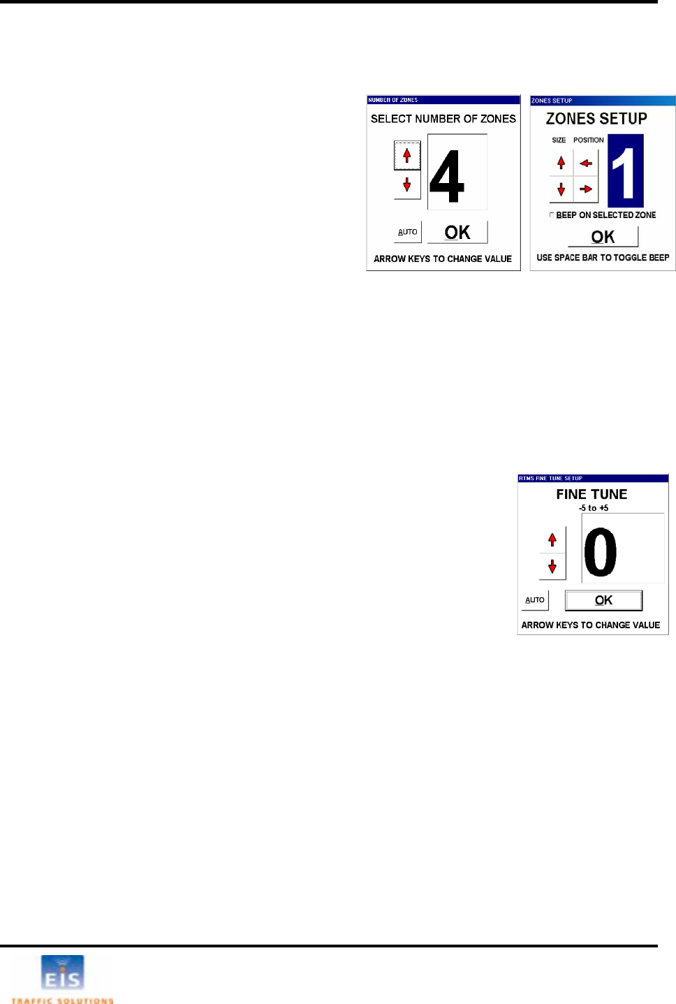
Manual Zone Setup - Side-Fired
• Use up/down keys or the window arrows to select
the number of zones required.
• Click
AUTO to initiate automated location of
selected number of zones,
or
• Click
OK or press ENTER; the ZONES SETUP window
will open.
• Type the zone number. It will be highlighted and
its icon (rectangle) on the main window will flash.
• Use left/right keys or on-screen position arrows to
move the flashing zone to the d .
Repeat process for each of the zon
• Exit
ZONES SETUP when finished.
Fine Tune Adjustment
“Splashing” is defined as a single vehicle that shows more than one target blip in adjacent detection
zones. This can occur when the zones’ positions do not line up with the lanes.
To reduce splashing the FINE of the detection zones with
ct to the lanes.
• Select
AUTO or use the manual procedure, described below.
ed. Active traffic needs to
e Tune setup, start with a setting of “0”.
ne whether the Fine Tune
n reduce splashing into a closer
une number; in a farther zone, decrease the Fine Tu
up/down arrow keys.
take effect and the display will turn gray while it is
ion zones that are wider than the default size. The
hicle is present anywhere in the enlarged zone. To define a larger
d
•
• Select ZONES; the NUMBER OF ZONES window will open.
esired position
es configured.
TUNE control is used to obtain a better position
respe
The FINE TUNE window includes the AUTO button, which activates the automated procedure.
• Select fine tune.
• The AUTO feature will fine tune the zones select
be in all lanes to ensure proper operation. Auto must be used with free flow
traffic; not in congested conditions.
Manual Fine Tuning
• For manual Fin
Observe the incidence of splashes and determi
umber should be increased or decreased. To
zone, increase the Fine T ne.
• Use the arrows in the window or the
A change in Fine tune setting needs a few seconds to
being processed.
Detection Zone Size
In some applications it may be useful to define detect
contact closure output will close if a ve
etection zone, do the following:
Open the
ZONE SETUP window.
• Highlight a zone.
• Use up/down keys or on-screen size arrows to increase/decrease its size.
EIS Electronic Integrated Systems Inc.
RTMS™ User Manual for Model K4 Draft 1 Page 17
Count Verification
T ver a period of time to a manual count
fo e commended.
The W ification procedure
is
zon
Perform the f
• RIFY button. The RTMS COUNT
•
At the
ba
lin time to start the
ount.
vehicles as they cross the
The S box will replace the Clear Counters box and the RTMS Count will be frozen.
or the zone in the corresponding box.
The d ent deviation terms is
displa ires zone setup correction to improve detection accuracy. The
then be repeated.
window displays the CLEAR TOTAL
• indows procedures to
ation
sets the internal speed coefficients used to calculate the average speed of
libration procedure used depends on traffic conditions.
r of calibration cycles (message periods). A minimum of 5 cycles
oefficients will not update if there are less than 8 vehicles detected
d. Increase the message period if the number of vehicles is less than 8 vehicles
volume less than 5 per
minute).
Here the coefficients are directly changed to bring the calculated speed closer to the estimated
speed.
o verify the zone setup, compare RTMS volume measurements o
r th same interval. Use of a hand-held tally counter is re
inRTMS program’s Count Ver
an aid for comparing RTMS counts in each detection
e to observer’s counts over the same interval.
ollowing steps:
• Select PERIOD and set it to 30 seconds.
Select VE
VERIFICATION window opens.
Tap the Space bar. A checkmark will appear in
the CLEAR TOTAL COUNTERS box. Get ready
to start counting.
end of the current message period the window
RTMS countckground blinks, the PC beeps and the
e is cleared, signaling the precise
c
• Select a lane and count
RTMS beam. Several observers may be enlisted
in the process, each counting traffic in one lane.
The RTMS COUNT for each zone will be updated at the end of each message period. Continue
counting until each lane has a count of at least 50 vehicles; this will usually take several message
periods. Stop counting at the end of the next message period.
• Tap the space bar.
TOP COUNTING
• Highlight a Manual count box and enter the manual count f
For the Forward-looking mode count verification is applicable to zone 1 only.
ifference between the RTMS and the manual counts in absolute and perc
yed. Deviation of more than 5% requ
verification process should
• To repeat the process, tap the space bar until the
COUNTERS box
To save the results of verification in a text file select SAVE. Use normal W
name and save the file using the Save As dialog box
• To exit to the main screen, select OK
peed CalibrS
The speed calibration process
traffic in each zone. The ca
• Automatic Speed Calibration is intended for use with high-volume traffic, flowing at stable
speeds. It requires per-lane reference speeds, which may be estimated or measured (e.g. by a
radar gun) and setting the numbe
is recommended. The speed c
per message perio
per period.
• Manual Speed Calibration is intended for very low-volume traffic (e.g.
EIS Electronic Integrated Systems Inc.
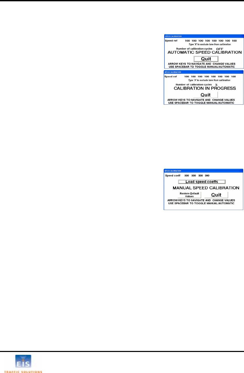
RTMS™ User Manual for Model K4 Draft 1 Page 18
Note: When setting up relo
to their default value
cated units in their new locations, all speed coefficients should be first reset
or the Quit button.
eed in the
from the
e up arrow
ATION IN
lash.
djusts the
sured speeds to the reference speeds.
successful for all lanes, review the speed data
d speed is within 10% of actual.
stment should be made. See Manual Speed
Side-fired Manual Speed Calibration
the screen.
s using the Manual Speed Calibration window.
Side-fired Automatic Speed Calibration
• Select SPEED CALIB to open the window.
• Use the left/right keys to highlight the Speed refer
each zone, ences for
Number of calibration cycles
Use up/down keys to set the desired ref•erence sp
highlighted zone box. Enter “X” to exclude zone
calibration process.
• Enter the number of calibration cycles by using th
key to increase it in multiples of 5. CALIBR
PROGRESS will f
At the end of each message period, the WinRTMS a
coefficients values of all active zones to converge the mea
• To verify that the Automatic Speed Calibration was
over multiple message periods to see if the average reporte
• If the difference is more than 10% a manual adju
Calibration below.
• Select Quit to exit.
• Select SPEED CALIB button and tap the space bar to open
the Manual Speed Calibration window. Zone boxes will show
the current coefficients. Select Restore Default Values to
restore defaults, if required.
• Compare the displayed speed measurement to your estimated
average speed in each lane.
• Use left/right keys to select zone and up/down keys to adjust coefficients proportionately to the
required change; as an example, if speed readings are 10% too low, increase that lane’s
coefficient value by 10%, if 10% too high then decrease by same percentage.
• Select Load speed coeffs to update all RTMS coefficients to the displayed values. Observe the
ements displayed on effect on average speed measur
• Select Quit to exit
EIS Electronic Integrated Systems Inc.

RTMS™ User Manual for Model K4 Draft 1 Page 19
RTMS Operating Modes - Details
• Select MODE. The RTMS MODE SETUP windo
• Choose the required mode for your application.
w will be displayed.
See descripti
T to
de
Default settings
Refer to Advanced
ges
on
below.
Re-selecting a Mode of Operation will reset the Threshold and ED
fault settings.
Parameters for chan
to settings
MODE Application
Threshold EDT
Side
Huse in highway and counting applications. Not
se at intersections.
The sensor detects presence and generates traffic
data in up to 8 zones.
Normal 200ms
fired For
ighway for u
Intersection For use in stop-bar detection Low 1000ms
The sensors detect presence in multiple zone
Traffic data is not generated. s.
Mid.
I r mid-block applications. Similar to
for
settings.
Medium 200ms
nte section Sidefired Highway mode; this mode is optimized
detection in urban
For use in
Forw
Hwy
vehicle Doppler-based speed measurement is
made when speeds exceed 15Km/h (10MPH).
Volume counts in up to 7 speed-bins are available.
ard Look
For applications demanding high accuracy speed
measurements. Normal 200ms
Zones 1, 2 and 3 are set as a speed trap for
accurate speed measurements.
Per
Alarm Forward
Look Adds programmable speed threshold and closes
contact #8 for 20ms when a vehicle exceeds that
threshold.
Intended for use in speed enforcement and warning
applications. Window for setup of threshold is
displayed when this mode is selected.
Normal 200ms
EIS Electronic Integrated Systems Inc.

RTMS™ User Manual for Model K4 Draft 1 Page 20
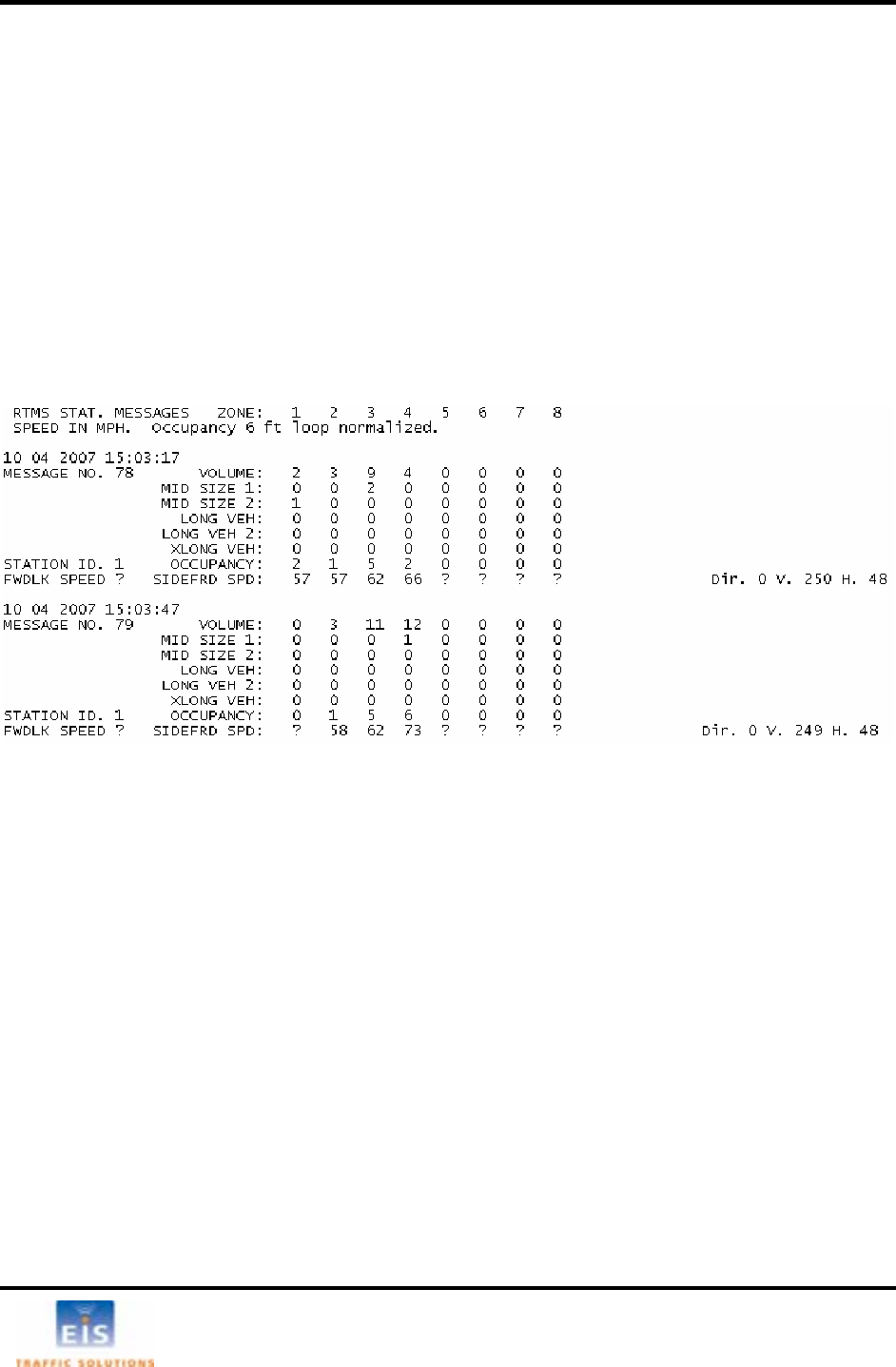
6 RTMS STATISTICAL TRAFFIC DATA
ide-Fired, Mid-Intersection and the two Forward looking modes generate statistical traffic data collected
oght area of the RTMS Setup
U onsist of:
• lume
• tion
•
• Volume in Length Classes - applies to the Side-Fired mode only. Up to 6 length classes are
available. Headway measurement may be requested to replace the Long Vehicle 1 measurement.
• Per vehicle speed
• Speed Bins - applicable to Forward Looking Mode only
Transmitted data consists of a base set of 4 messages, Long Vehicle Volume, V and
Speed; plus any additional data selected for transmission.
The standard message in Hex file format as transmitted by the RTMS is:
FF1B090000000100000000FDFE
F 080B000
F 20506000
FF120B4E6D6B80F0
I the RT
Message Period
M d is th g are s in
1 ement riod range from 10 to 900
seconds. Earlier firm from 10 to 600 seconds.
Use 30 second message periods for setup functions. A 300 second
m e
a tions will gene periods that are one minute or less.
• Select PERIOD ed
value.
• Click OK, or p of
three seconds
Sver the selected “Message Period”. The data is displayed in the upper ri
tility main window and transmitted over the data port. The measurements c
Total Vo
Occupancy - available as integer (default) or one decimal place resolu
Average Speed
olume, Occupancy
F10090303
F1109020
00000061F
000000110
F0F0F000F03086
nformation on MS protocol is available on request from EIS.
essage perio
0 second incr e time interval on which traffic data is reported. Messa
s. Firmware version 6.8 and higher has a message pe
ware versions have a range
e periods electable
essage period is sug
pplica gested for counting applications. Real-tim
rally use message
. Use the up/down keys or arrows to set the requir
ress ENTER. The new period will start after a delay
and message numbering will be reset to 0.
EIS Electronic Integrated Systems Inc.
RTMS™ User Manual for Model K4 Draft 1 Page 21
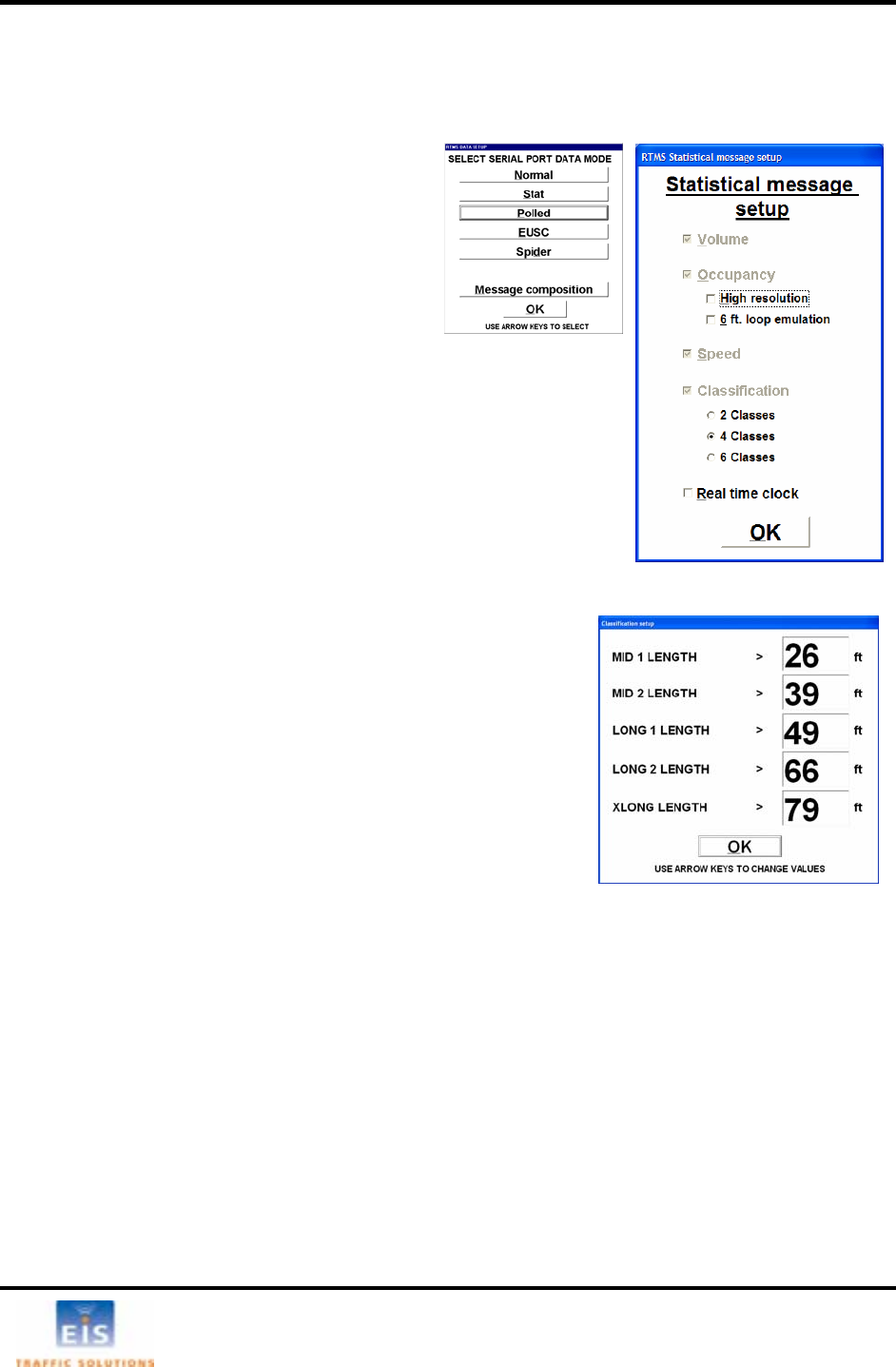
Vehicle Classification
Setting the RTMS for vehicle classification (side-fired mode only) is a two stage process:
1. Defining the number of classes.
2. Defining the class boundaries.
S
The
o .
vehicle volumes only.
vehicle volume, volume, occupancy and speed).
messages
2 messages
s window, open the
SIFICATION and
ngths defined. Only the length classifications that were chosen
will show on this screen.
e ti
• Select DATA m
t ng the number of vehicle classes
ode then Message
composition.
Statistical message setup window will
pen
• Select 2, 4 or 6 classes
2 Classes (default) provides the reporting of long
Transmitted data will consist of 4 messages: (long
4 Classes adds Mid and XLong
6 Classes adds Mid2 and Long
• After completing selections in thi
ADVANCED menu, select CLAS
define the classes selected.
he length of cars is pre-set, only vehicles longer than cars can have T
le
in the classification menu
For best results, ensure that length differences are greater than 3m
[10 feet] between size classifications. The closer the separation the
greater the potential “merging” of classes.
EIS Electronic Integrated Systems Inc.
RTMS™ User Manual for Model K4 Draft 1 Page 22
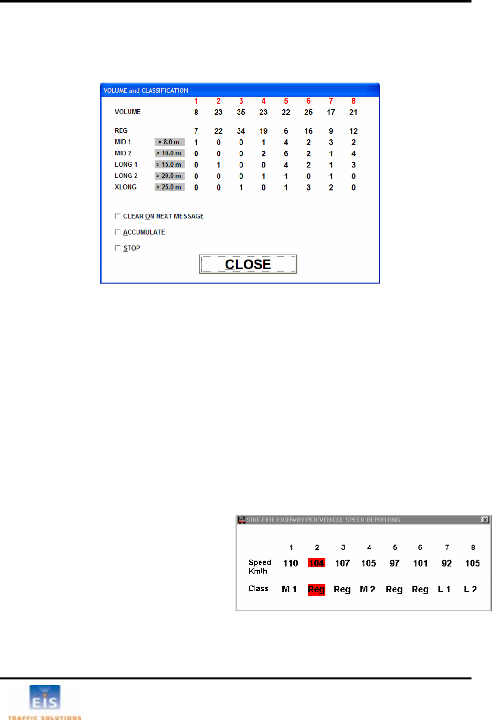
Class Measurements Display
fined vehicle classes is available by clicking the CLASS button. This opens
he , and boxes are provided as aids to verify the vehicle
ocedure.
• Click
ACCUMULATE to start accumulation of counts over several message periods
bers of vehicles have accumulated.
Modify class length limits to achieve best correspondence to desired vehicle classification (see
Advanced Parameters/Classification in the next section).
• Use the Side-fired Highway Per Vehicle Reporting real time display (shown below) to verify that
Class limits provide required discrimination between vehicle types.
Per Vehicle Speed Display
The per vehicle speed selection box is located below the statistical data area.
When selected, an additional window will open
showing the speed of each vehicle and its class.
The display is highlighted in red while a vehicle
transits the detection zone. The data is displayed
until overwritten with the data from the next
vehicle.
The RTMS will send this data over its
communication port in real-time along with the
Statistical Data at the end of each message period.
In forward looking mode the Per Vehicle Speed is displayed in the main window.
The display of volumes in de
the Volume and Classification window, shown below.
Figure 14 - RTMS Utility Verification Screen
TCLEAR ON NEXT MESSAGE ACCUMULATE STOP
counts in configured classes, similar to the volume count verification pr
• Click
CLEAR ON NEXT MESSAGE to clear all counts
• Click STOP at the end of a message period after sufficient num
• Compare manual counts to the RTM
•
S counts.
EIS Electronic Integrated Systems Inc.
RTMS™ User Manual for Model K4 Draft 1 Page 23
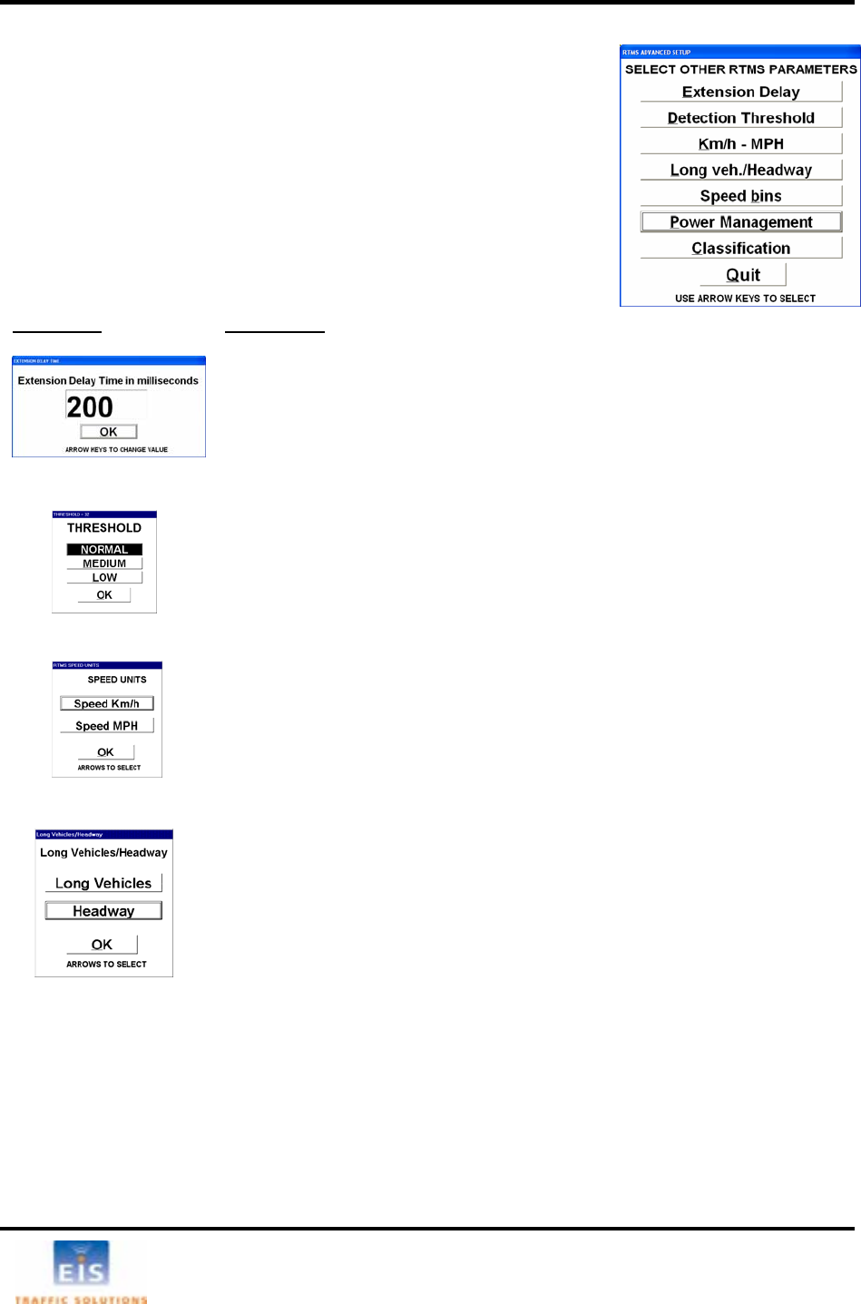
Advanced Parameters
• Select ADVANCED to display the menu of RTMS parameters
described below.
The number of displayed functions depends on the RTMS model and
firmware version. The window shown at right is for RTMS X3/K3
models. Parameters are set or edited as follows:
• Select the desired parameter and follow instructions below for that
parameter.
Parameter Description
Extension Delay window; allows the user to change the default value.
• Highlight the EDT value (Click or use left/right keys).
• Overwrite or use up/down keys to change value.
• This parameter should not need to be changed from its default value.
Detection Threshold Allows the user to change the default value. Lowering thresholds effectively
increases the sensitivity. Changes made will take up to 5 seconds to take
effect.
to main window.
• Select OK to return to main window without changes.
the RTMS is always in km/h. If MPH is selected,
rrent setting is
to main window without changes.
in units of 0.1seconds.
• Select either Long Vehicles, or Headway, as required, and return to
indow.
es.
• Select Normal, Medium or Low and return
• This parameter should not need to be changed from it’s default value.
Km/h – MPH The speed data reported by
the WinRTMS program will report the speed from in MPH. Cu
shown in the Traffic data area.
• Select required units.
• Select OK to return
Long Veh./Headway This parameter applies to the Sidefired Highway Mode only. Headway is the
average time/gap between vehicles measured
main w
• Select OK to exit without chang
EIS Electronic Integrated Systems Inc.
RTMS™ User Manual for Model K4 Draft 1 Page 24
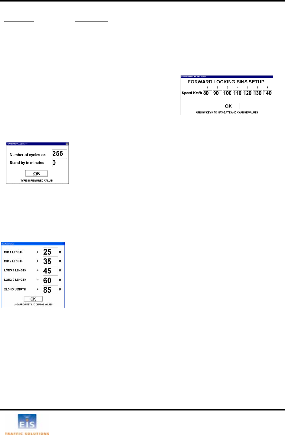
Parameter Descrip
tion
SSee Definitions
bin.
eed limit.
ing of a bin automatically defines the lower limit of
educe each bin to minimum
and set to desired level.
• Key ENTER or click OK to
confirm when all required
values are displayed and
main window.
Power Management
Classification
nserve
ba r
T p
e Period. Set the above as desired.
S
D ne l
power. Maximum time off is 4 hou
er limit for classes other than “Regular”. The
nu b is selected in the Statistical Message Setup
w
Shown is the window displayed when 6 classes are selected (firmware 6.8
and up). Displayed units (feet/meters) correspond to the km/h – MPH
settings as displayed and return to
ote 1: For RTMS with firmware below 6.8, classes are defined in terms of a
vehicle length multiplier rather than length.
Note 2: Long 1 measurement will not be available if headway is selected
(see above) or if the message period is greater than 300 seconds.
Real Time Clock Change
The RTMS’ Real Time Clock may require adjustment for any of the following:
• To correct RTMS clock due to time zone change.
• To perform seasonal changeover between Standard and Daylight Saving Time.
• To correct accumulated drift between RTMS clock and the traffic management centre’s clock.
The WinRTMS will copy the PC’s clock setting to the RTMS on selecting LOAD RTMS. Ensure the PC’s
clock is correct before connecting to an RTMS.
peed bins Additional Forward Looking Measurements
• Use
LEFT/RIGHT keys or click to highlight a
• Use
UP/DOWN keys to set the bin’s upper sp
• The upper limit sett
the next bin. To reset previous settings, r
return to
A cles to collows RTMS powered by batteries to be operated in cy
tte y power. This is a factory option.
wo arameters are defined:
• Number of cycles on (Message Periods, range 1-254)
Defines the number of Message periods the sensor operates. It will go into
standby 1-second after the last period. Time on depends on the length of the
Messag
et either or both to 0 or 255 to turn Power Management off.
• Standby in minutes (Range 1 to 254).
efi s the number of minutes the sensor is in standby and draws minima
rs 14 minutes.
• Click OK or press Enter to accept settings as displayed and return to
main window.
A wllows the user to set the lo
m er of classes displayed
indow (opened via Data/Normal/Message Composition).
setting.
• Use LEFT/RIGHT keys to highlight a class.
• Use UP/DOWN keys to adjust its lower length limit.
• Click OK or press Enter to accept
main window.
N
EIS Electronic Integrated Systems Inc.
RTMS™ User Manual for Model K4 Draft 1 Page 25
Data Recording
Win S
e data record will open for
folder selection and file
• Select folder to store th m) and name it.
The suggested name u
window shows that recordin
• Click the STOP button to st
The data file will have extens eters that have been selected Speed
units are identified in the header.
Eight columns are always genera s is always report 0 and speeds will
always report “?”. The file also p g and a diagnostic indicator in every message.
Fig. 17 shows a sample file generated by RTMS with Rev 6.8 and 6 classes reporting.
RTMS can record RTM
• To initiat
data to a text file on the PC’s disk.
in select File then Record Data to File. A Save As dialog boxg
naming.
e file (default folder is the location of the WinRTMS progra
sho ld identify the RTMS and date of creation. The RECORDING DATA
g is in progress.
op recording.
ion .asc. The file will contain all param
ted. Volumes in unassigned zone
rovides a voltage readin
Figure 15 – Sample RTMS data file
Note The volume m
(cars), displaye
If the message s greater than 300 seconds, the long vehicle message is replaced
with the most s easurement under these
conditions is LON
If per vehicle speed measur
message period data.
easurement represents total number of vehicles. Regular vehicle volumes
d in the Volume and Classification window are not shown in the asc files.
period i
ignificant byte of the volume. The volume m
G VEH * 255 + Volume.
ements are selected, this data is presented in the .asc file ahead of the
EIS Electronic Integrated Systems Inc.
RTMS™ User Manual for Model K4 Draft 1 Page 26
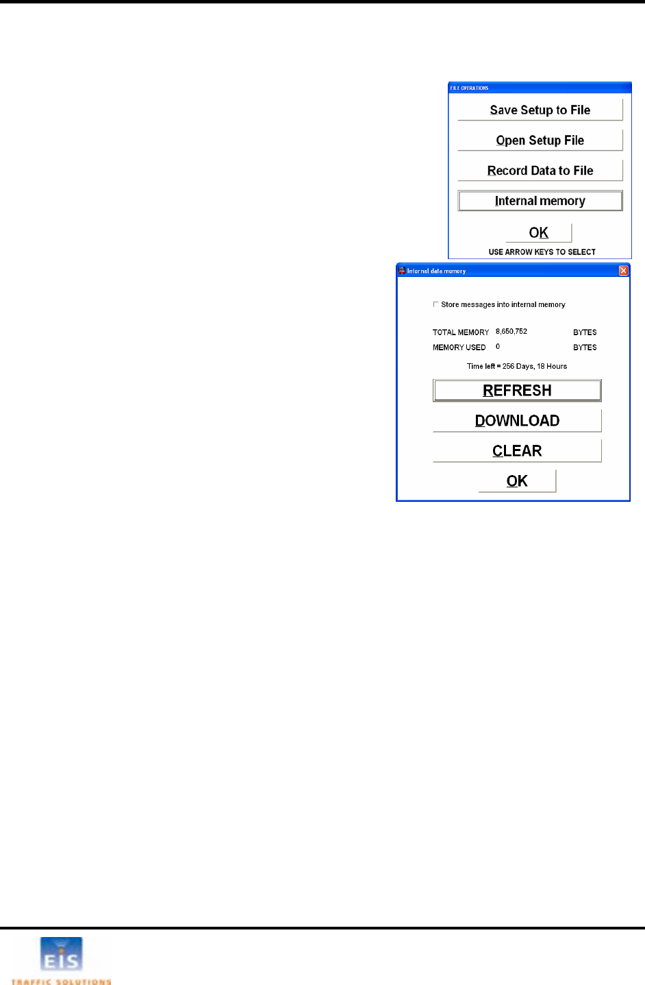
Storage and Downloading of Traffic data
data using the internal memory:
essage composition is
•
• displayed
d with internal
internal memory box.
ATA button on the main display will show an asterisk (*) next
to the mode to indicate that data is being store in the internal
memory.
• Click the REFRESH to update the MEMORY USED
display (to verify that data is being stored).
• Click OK to close the window.
To retrieve and clear stored data perform the following steps:
• Open the Internal data memory window.
• Click DOWNLOAD to start downloading.
• Enter a file name and select a folder before the
download can start.
Downloads should be done at the highest connection speed
available. A full memory will take just over 12 minutes to
download at 115200 bps; 146 minutes at 9600 bps.
The lower left corner of the main window will
licking OK will close the Internal cting the download process. The
ecording data window will continue the display the progress of the download.
g the
• To era
action
RTMS K4 sensors are equipped with internal memory. To record
• Ensure the Message Composition section has been
set. The ability to change the m
disabled while data storage is ON.
Select FILE.
Select Internal Memory. This option is only
when connected to an RTMS equippe
memory.
• Click the Store messages in
The Internal data memory window displays the amount of
memory installed, memory used; and time left based on the
selected message period and message composition. The
D
display the amount of data left to download.
data memory window without affeC
R
Clickin STOP button will terminate the download before it is completed.
se stored memory, click CLEAR. A dialog box will be presented to confirm. Accept or reject
, as appropriate.
EIS Electronic Integrated Systems Inc.

RTMS™ User Manual for Model K4 Draft 1 Page 27
Data Modes
The DATA button is used to select how the RTMS communicates with the communications channel.
T n.
The N RTMS. In normal mode,
th s onstant communication with the WinRTMS
pr
• ns
used to create the target blips displayed on the
al
each Message Period the sensor transmits statistic traffic data.
hicle blips are not displayed on the screen
ere reduced number of messages is desired and polling
s, TCP/IP or Cellular Packet Data applications.
he different modes determine what data is transmitted and whe
ormal mode is used to set up the
e ensor is in c
ogram. Data transmitted by RTMS includes:
Target messages every 100 mSec. This message contai
the data
screen.
• Per vehicle speed, if selected.
• Statistical data at the end of each message period.
The Message Composition button displays the Statistic
Message Setup window.
Other data modes provide the following:
Stat At the end of
Target messages are not transmitted; ve
in this mode.
For use in applications wh
is not required. As example
Polled The RTMS transmits statistical traffic dat
receip a for the last message period only on
r.
e with multiple RTMS on a single
collision detection; RS-232 and RS-485
t of a polling message with its ID numbe
Polled mode is used to communicat
communication channel that does not have
are examples.
WinRTMS, in Multi-Drop mode, can poll, display and record traffic data from several
RTMS, connected on the same communications channel.
EUSC This mode is used by the EUSC System for Traffic Man
used when an RTMS is connected to a system using thiagement. This mode is only
s communication protocol.
Spi s used when the unit is connected to an EIS SPIDER controller. The
communications protocol is specific to this application. Select only if the RTMS will
be linked to a SPIDER controller.
der This mode i
EIS Electronic Integrated Systems Inc.
RTMS™ User Manual for Model K4 Draft 1 Page 28
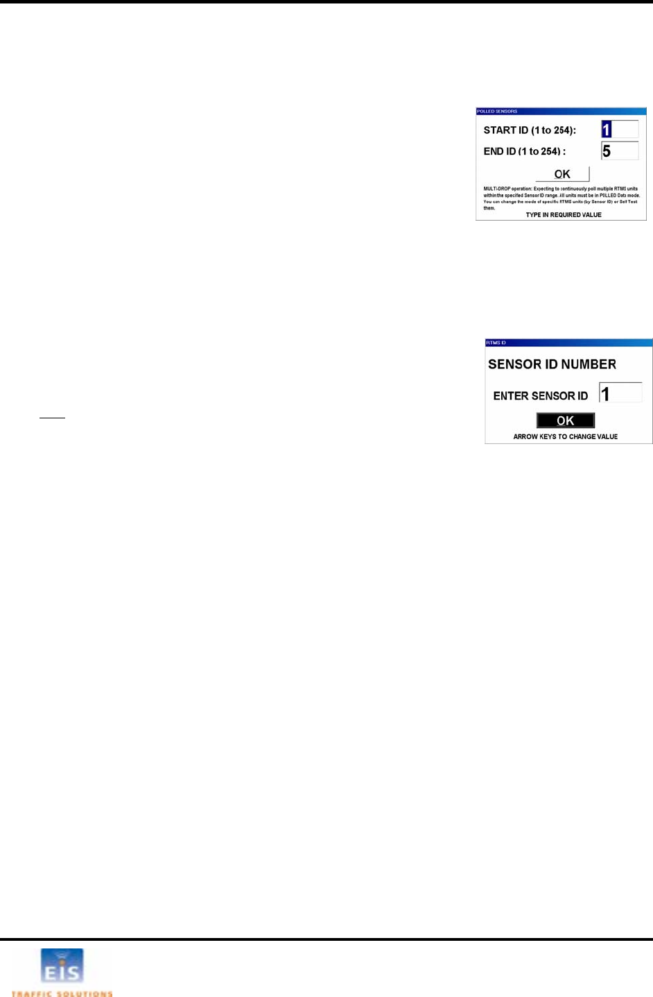
7 OPERA
TING WINRTMS IN MULTI-DROP MODE
• Open the program and wait for the main screen display.
ge of
st to
ha and
WinR y will
be ov by new data. The data can be recorded as described in the
s
de
cific sensor in Multi-Drop mode to allow viewing and changing
se, polling of other sensors is stopped. To access a
ensor proceed as follows:
the DATA.
lect NORMA
• Specify the SE
only
The WinRTMS program, set to its multi drop mode, is used to verify the operation of RTMS sensors
operating in POLLED mode.
• Open the
TOOLS menu, select Multi Drop and set the ran
RTMS IDs.
WinRTMS will transmit polling messages in sequence from lowe
ighest. RTMS sensors answering the poll will transmit their dat
TMS will display it in the statistical traffic data area. The displa
erwritten
ection on Data Recording.
Accessing a specific sensor in Multi-Drop Mo
WinRTMS has the ability to access a spe
e sensor’s setup. When this capability is in uth
s
• Select
• Se L mode.
NSOR ID number in the window using up/down keys
.
• Select OK
T ied sensor
unit, automatically re
setup of the unit can n
• To select anot
sequence with
he specif ’s data mode is now changed to Normal and WinRTMS communicates with that
ading its setup and displaying its parameters, target blips and statistical data. The
ow be changed as required.
her sensor for access, restore this RTMS to Polled mode and repeat above
the new Sensor’s ID.
EIS Electronic Integrated Systems Inc.
RTMS™ User Manual for Model K4 Draft 1 Page 29
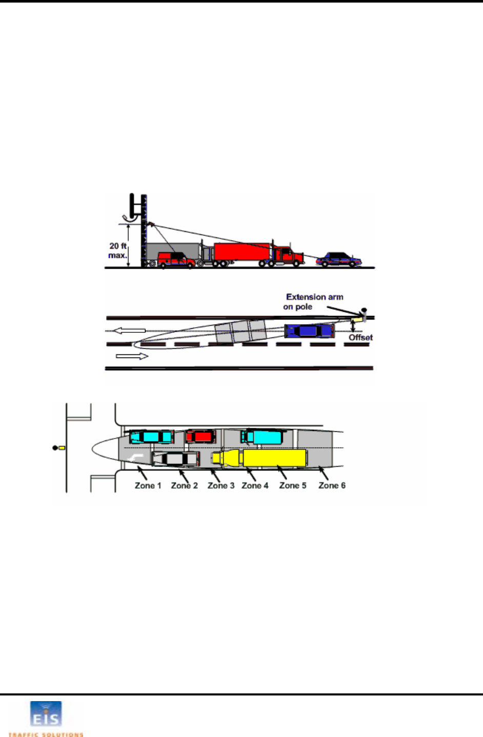
8 INSTALLATION AND ZONE SETUP - FORWARD LOOKING MODE
m interfering structures as shown below.
T s ing at receding traffic is preferable.
[17 feet] and 6m [20 feet].
the sensor. This will ensure
may be mounted on a roadside pole, if the offset (distance from sensor to
lane centerline) is less than 3m (10 feet). Extension arms can be used to reduce offset.
Forward-looking Mounting and Aiming
Sensors are mounted on a sign-bridge or overpass away fro
he ensor can be aimed at approaching or receding traffic, aim
• Mount the sensor above the center of the lane at a height between 5m
• Point it parallel to the monitored lane.
• Mount it level side to side.
• Looking from behind the unit, aim it to a point about 10m [33 feet] from
a sufficiently long footprint but restrict its width to a single lane.
• Forward-looking RTMS
Figure 16 - Forward Looking mounting options
Figure 17 – Queue Detection
RTMS can be set up in forward looking mode when serving off-ramp or T-intersection queue
applications. In such applications, the RTMS is aimed farther than in the traffic monitoring highway
applications. One or more detection zones are defined to span the required distance (within the range
limit of the RTMS). The width of the microwave beam may cover two lanes; the sensor cannot
discriminate between lanes.
EIS Electronic Integrated Systems Inc.
RTMS™ User Manual for Model K4 Draft 1 Page 30
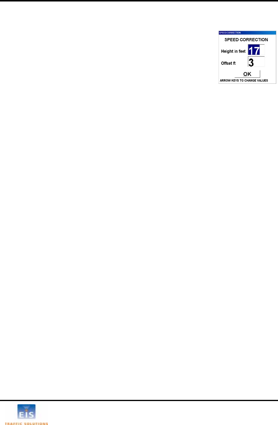
Zone Setup – Forward-looking Mode
When forward looking mode is selected, WinRTMS will p
setting the height and offset parameters. resent a window for
d menu for changing between metric and
A o
• n the Zone
Setup window.
The Wizard will determine the best location for the 3-zone speed trap. If it cannot find a good speed trap
due to incorrect RTMS aiming, low volume or other causes, it will display warnings.
Manual Zone Setup
• Set the number of zones to 8 and position all zones in sequence with the first zone at
approximately 8 meters from the sensor (farther if the sensor is higher than 5M).
Observe approaching (or receding) vehicles in the lane as "waves" of blips and adjust the tilt and sway
angles so that blip waves from small vehicles go through at least 5 of the 8 zones and so that vehicles in
adjacent lanes do not show blips in the zones. Detection of vehicles from an adjacent lane indicates that
the sensor is angled in that direction or aimed too high.
• Set Fine Tune control to +5.
• Observe approximately 50 vehicles. Find three consecutive zones, for which vehicle counts are in
close agreement with each other. The location of these three zones will form the speed-trap. Note
their position on the ra bers 1, 2 and 3 over these
three consecutive zone positions, then reduce the total number of zones to 3.
• Only Zone #1 is used for volume and occupancy data. Zone #2 and #3 complete the speed trap
and help determine the direction of travel.
Forward-Looking Speed calibration
The RTMS provides Doppler speed measurements and does not need to be calibrated for this, only the
Speed Trap length for slow moving traffic needs to be calibrated.
Ensure that the main screen box Per Uncheck this box to suppress
porting of per vehicle data, if desired, after completion of speed calibration.
• Use left/right keys to highlight a parameter and up/down keys to enter the
value. Press Enter or click OK to accept the displayed parameters. The
length units will be decimeters or feet depending on the units used for
reporting speeds.
• See Km/h-MPH in the Advance
imperial units.
ut matic setup
Initiate the automated zone setup either by clicking the Wizard icon or AUTO button o
nge scale and using ZONES, move zones num
Vehicle Speed is check-marked.
re
In the Forward-Looking Highway mode, the RTMS uses the Doppler speed, as the reference speed to
calibrate the speed trap. Speed trap measurements are used when speeds are below 10 MPH [16 km/h]
where the Doppler measurement does not function.
EIS Electronic Integrated Systems Inc.
RTMS™ User Manual for Model K4 Draft 1 Page 31
When SPEED CALIB is selected, a choice of automatic or manual calibration is presented:
calibration to 10.
• nge i.e. increase if measured speed is
• ference speed and percent deviation of the
average speed from the reference are updated at the end
period.
LLATION FOR STOP BAR DETECTION
• Select the required mode of calibration.
• Set the number of cycles for automatic
• In manual calibration, use left/right keys to highlight the
zone length box.
Use up/down keys to adjust the zone length in proportion
to the desired cha
low.
The Doppler re
of each message
• For manual calibration - when deviation from the reference
speed is acceptable click LOAD.
• Click OK to exit.
9 RTMS INSTA
Figure 18 – RTMS Intersection Installation
Intersection Controller Settings
Intersection Controllers can be set into one of two modes Lock and Delay. When the Controller is set
into the Delay mode, the delay setting must take into account the RTMS’ extension delay time (EDT)
setting (Default EDT = 1 sec, Maximum = 3 seconds). The actual controller delay will be the sum of the
two settings.
Loc
tored widens
e s
Whe
reco
RTMS as close to optimal as possible.
ate poles at positions that allow aiming at
the stop bar while perpendicular to the traffic
lanes.
Mounting the RTMS sensors across the road
from the traffic lanes to be moni
the footprint by increasing the set-back and
n ures no occlusion of left-turn lane.
n existing poles are not in optimal
position, use of extension arms is
mmended to bring the position of the
10 96
-+
EIS Electronic Integrated Systems Inc.

RTMS™ User Manual for Model K4 Draft 1 Page 32
10 RTMS TROUBLESHOOTING GUIDE
F ts mainly of ensu
comm e is confirmed by presence of the RTMS
se ng ommand and responded by sending the
pa t corner of the screen, denoting data
transm
RTM
The R Select TOOL and Self-Test in
norma
The t ns and locates hardware faults. The "All tests complete System OK!"
m sa llowing is a list of Self-Test messages
descri
.......
signal fault
- Microwave module fault
- Modulator memory fault
Saturation signal level
The Self-T r one second each in sequence. Operation of the
c ler display, ohm-meter or any other suitable device
s
T d action in troubleshooting power and communication
p
T
SSuggested action
ield troubleshooting of the RTMS consis
unicating. Communication with the sens ring that the unit is powered and
or in Normal mod
tti s on the menu buttons (RTMS has received the Read C
rameters), and by the flashing of the indicator in the lower righ
ission activity.
S Self Test
STMS provides a diagnostic test of its internal functions.
l mode to run the self test.
est checks internal functio
the
es ge is displayed on the screen if no faults are found. The fo
bing a fault:
lt .............................................................................................................Power supply fau
- Modulator
- Program memory fault
- DSP fault
- Gain too low or ADC fault
- Logic failure
- No signal
-
est will also close the zone contacts fo
ontacts can then be verified using the control
howing continuity.
he table below outlines symptoms and suggeste
roblems:
able 5
ymptoms Possible causes
T
th
“Communication Error”
message is displayed.
wered
• Cable problem
fault
• PC unable to
communicate with the
RTMS due to H/W
problems
• Check that the supply voltage is
within limits at source and at the MS
connector. Voltage outside the limits
(too low or too high) will cause
• Check cable pin-out and continuity.
• With power applied to the RTMS
and DB9F disconnected from PC,
connector. If the voltage is not
present there could be a hardware
fault in the RTMS serial port or
power supply.
• Check that PC’s serial port is
operational (10V present between
pins 3 and 5)
imeout has expired and
e main window with • RTMS is not po
• Hardware
check the RTMS serial Port by
measuring approx. 10V between
pins 2 and 5 of the DB9F RS-232
power supply to shut down.
Polling range window is • WinRTMS is in Multi- • Click OK on the polling range
EIS Electronic Integrated Systems Inc.

RTMS™ User Manual for Model K4 Draft 1 Page 33
displa d on start of
WinR S. drop mode. ye
TM window; RTMS Setup default screen
will be displayed.
• Select TOOLS, Change to Direct
mode, if direct access to one RTMS
is desired.
PC and sensor are
ommunicating (Sensor
n
s
• RTMS is not in Normal
mode.
• Unit is not aimed
properly.
• MW module fault.
• Ensure the unit is in the Normal
mode.
• Check sensitivity setting. See if
targets appear when sensitivity is
•
c
settings are displayed o
buttons) but target “blip
“are not shown on the
main screen. • Low Sensitivity. increased.
• Internal parameters
corrupted.
Cycle power to unit and then edit
parameters (mode, sensitivity, zone
setup, etc).
• Run Self-Test if above not
successful. Report findings to EIS.
PC a
commun
settings
buttons) u
“are not s
main sc n
M is not in Normal
d
s not aimed
properly.
ensitivity.
parameters
corrupted.
• Ensure the unit is in the Normal
mode.
• Check sensitivity setting. See if
targets appear when sensitivity is
increased.
• Cycle power to unit and then edit
parameters (mode, sensitivity, zone
setup, etc).
nd sensor are • RT S
o e.
icating (Sensor
re m
a displayed on
b t target “blips • Unit i
hown on the
ree . • Low S
• Internal
• MW module fault. • Run Self-Test if above not
successful. Report findings to EIS.
Main screen shows target
on buttons.
sults are not
• RTMS transmits and
received data but
RTMS has not
the
READ
• Check cable to ensure continuity
COM port’s pin 3.
blips but no zone icons or
parameters WinRTMS displays between MS connector pin T and
Self-Test re
displayed on PC screen.
received
WinRTMS
command.
The setup program
unable to read an RTM
with DSS modem (targ
is
S
ets
displayed but sensor
settings are not
displayed).
• Pin “a” is not cabled.
PC cannot send any
commands and has
not received setup
•
data.
Examine cable and correct to
include pin “a” cabling to DB9F pin 4
(DTR) if omitted.
Cannot establish
communications with an
RTMS equipped with
internal data storage.
• 10-12V is not present
at MS pin “b”.
•
•
Examine cable and correct to
include pin “b” cabling to DB9F pin 7
(RTS) if omitted.
Examine any modem cable used for
conformance to the cabling
diagrams.
EIS Electronic Integrated Systems Inc.

RTMS™ User Manual for Model K4 Draft 1 Page 34
11 WARRANTY AND SERVICE
EIS Warranty
EIS Electronic Integrated Systems Inc. warrants this product to b defects in material and
tw y ry.
u o r
y
p disassem TMS unit.
Such actio l i
Cont e unit requires serv
EIS warrants that its software and firmwa ed for u
programming instructions when properly installed. EIS does not w r
o rr
rou e
est sho oked with the unit inst
ce
s to operate, ple g i
Manual or call EIS technical to a
remotely for testing and support pur
EIS Inc. will repair or replace at its option, any components, w
warranty period. Buyer shall pay for shipping charges to EIS. EIS will
aire vo
or whe
service sh rma nt:
ntact i
ber roblem who may be contacted by EIS
informat
m r mb
n of th at cond
ed? Wh lf Test
tu
number. Contact EIS Customer Support prior to shipping
ndise to obtain it.
ed in un
erial betw d inner carton e
strong tape or strapping.
voices and Wa i
"Shipped to Manufacturer for Repair", and “Canadian G
to avoid repayment of duties and taxes.
e free from
workmanship for a period of
abuse by the buyer, or una
specifications is not covered b
Do not attem
o ears from date of delive
th rized modification, impropeDamage to the product due to accident,
installation, or operation outside the
the warranty.
CAUTION
t to open, repair or ble the R
n (breaking the seal) wil
act EIS if th
vo d the warranty.
icing.
re designat se with the instrument will execute its
arrant that operation of software o
firmware will be uninterrupted
Service Information
The RTMS does not require
installation procedure. Self-T
performed indoors may produ
If the unit fail
r e or free.
tine maintenance. It is recomm
uld be inv nded that the Self-Test is included in the
alled and aimed at a road. Self-Test
erroneous results.
ase refer to the troubleshootin
support. An RTMS connected
poses.
gu de in Section 10 of the RTMS User
dial-up modem can be accessed
hich prove to be defective during the
pay shipping charges and
insurance for warranty rep
repaired outside of warranty
Units returned to EIS for
d product. Buyer will be in
n no fault is found.
ould include the following info
nformation of owner.
of someone familiar with the p
ion if necessary.
iced for repair and shipping of product
tion with the shipme
• Name, address, and co
• Name and telephone num
personnel for further
• Model number, serial nu
• A complete descriptio
equipment was attach
• Shipping address for the re
• Return Merchandise Authori
mercha
be and software revision nu
e problem. e.g. under wh
at was the result of the Se
rn.
zation
er.
itions did the problem occur? What
diagnostic?
The unit should be shipp
one inch of packing mat
should be sealed with
Note: Shipping papers, i.e. Commercial In
the original container. If it is
een the unit an available, there should be approximately
.g. plastic bubble-wrap. The carton
y B lls, should include the statement
oods being Returned for Repair”
EIS Electronic Integrated Systems Inc.

RTMS™ User Manual for Model K4 Draft 1 Page 35
12 SPECIFICATIONS
ro rea Mic wave Signal and Coverage a
12°
Side lobes
Beam width
Range
Number of detection zones
easurements, their Accuracies and Ranges
Center Frequency 24.125 GHz
Bandwidth 45MHz
Power Output 10mW
Beam width – horizontal (azimuth) >-20dB
– vertical (elevation) 40°
3-60m (10-200feet)
8
M
Measurement % Error * Range
Per lane Volume - Sidefired
fired 5% 0-255 0-65535 for MP>300 sec
5% 0-100 %, 1 decimal place resolution
ength – Sidefired 10%
0-160km/h (100mph)
low speed
barriers, etc.) will result in “splashing”
•mes in the speed-trap
r obstructions within the trap range or incorrect height or offset
Mec
Weathe
Mountin universal ball-joint bracket. Vertical and horizontal
brackets are available. Lynch pin locking allows quick sensor
replacement without disturbing the aiming.
Allowable pole flexing Less than 5 degrees.
Per lane Occupancy - Side
Per lane Classification by l
Volume and Occupancy - Forward-looking 2%
Average Speed - Sidefired 7% 0-160km/h (100mph)
Average Speed - Forward-looking 2%
Range Resolution 3m (10 ft.)
Resolution of Time events 10 ms
Accuracy Performance Conditions
Error performance parameters outlined above are achieved under normal, high-flow traffic conditions and
are subject to proper installation and setup. Reduced accuracy (higher errors) will be experienced under
the following conditions:
• Low speed, high congestion conditions: The RTMS may slightly over-count at
conditions (below 1mph)
• Improper selection of installation site: insufficient set-back, height beyond the recommendation,
obstruction of monitored lanes by barriers or high fences.
• Improper fine tune setting for the road geometry (lane width,
and, therefore, over-counting. In some cases, attempts to cover too many traffic lanes with a single
RTMS may result in inability to find a correct fine tune setting and compromised performance.
In Forward-Looking Hwy configuration, high variance between the volu zones due to improper aiming o
parameters may result in higher speed and length measurement errors.
hanical
Enclosure dimensions 22x15x19 cm (8.5 x 6 x 7.5 in.)
Overall dimensions 22x15x25 cm (8.5 x 6 x 10 in.)
Weight 1.3-2.2 Kg (3-5 Lbs.) depending on options
Enclosure Polycarbonate
rproofing NEMA-4X and IP-65
g Zinc plated steel
EIS Electronic Integrated Systems Inc.

RTMS™ User Manual for Model K4 Draft 1 Page 36
Power Requirements and Consumption
C or DC
r 24VAC.
ed fusing (external) 2A s um
nsumption (Standard Power) 2.7 W
of options DSS = 2.0 W, TCP/IP =1.2 W
115±-60Hz, 3W
voltage
wer
dard, additional port Optional
justa and 115200
.
tance depends on se peed: 200 -1000 ft.
•0m (4000 feet).
0 feet.
emotely or locally
S g
The RTMS withstand
al e
E
• RTMS standard power requirement 12-24V A
• Over-voltage shutdown limit 34VD oC
• Recommend low blow minim
• Automatic recovery from power failure Within 5 seconds, with DSS – 20 seconds
• Power co atts
• Additional Power consumption
• Comm 20V AC @ 50ercial AC power option
Interfaces
Zone Contact Ratings
• Maximum current 100mA
• Maximum 400V
• Maximum dissipated po 300mW .
Data Ports
• USB 2.0 with range up to 30 feet
• One isolated port Stan
• Ports operating at no parity, 8 bit, 1 stop bit ble speed between 2400 at ad
bits/sec (bps)
• RS-232 operating dis lected s
RS-485 option extends range up to 120
• Optional Ethernet port with range up to 3
Flash Upgrade
Available over data port r
ur e immunity
±s 1kV surge (rise time = 1.2 µsec, hold = 50µsec) applied in differential mode to
l lin s, power and output, as defined by IEC 1000-4-5 and EN 61000-4-5 standards.
nvironmental Conditions
Operating limits Shipping and Storage
T
Humid
5g 10ms half sine wave
ph]will not degrade performance
tion (rain or snow)
• US FCC Rule part 15 Clas
The RTMS is designed for Mean Time Between Failures (MTBF) of in its operating environment of
90000 hours [10 years].
emperature range -37 to +74°C [-35 to 165°F] -40° to 80°C [-40° to 171°F]
ity Up to 95% relative humidity Up to 95% relative humidity
ion 2g up to 200Hz sinusoidal Vibrat
Shock
Wind Winds up to 160 km/h [100m
Precipita Up to 100mm/h
Electromagnetic Interference
RTMS Model K4 is certified to meet
s A, Canadian CSA C108.8 M1983 Class A and CE mark requirements.
Reliability
EIS Electronic Integrated Systems Inc.
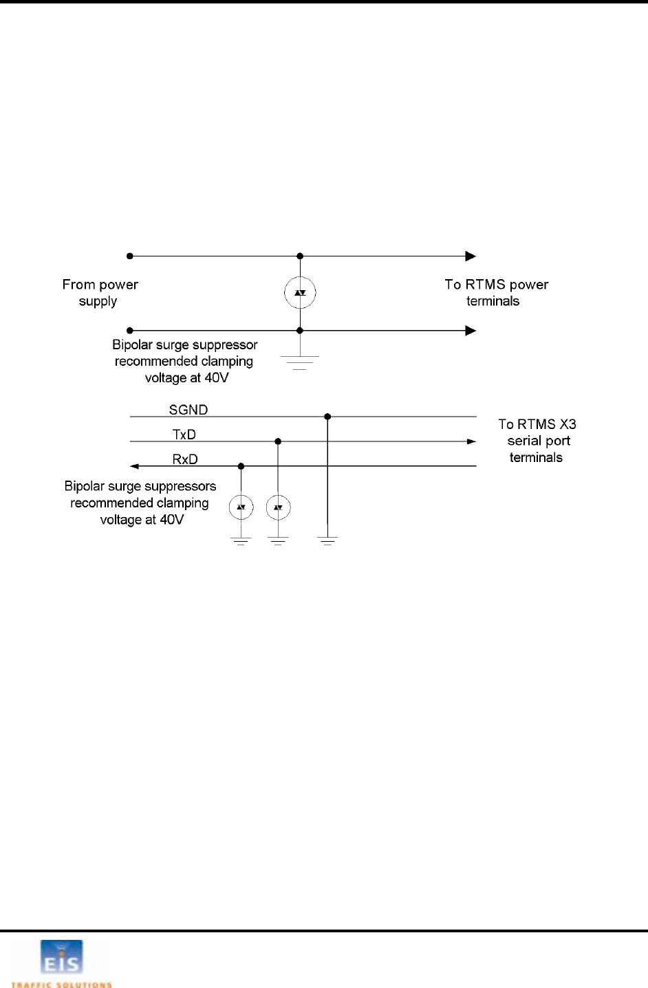
RTMS™ User Manual for Model K4 Draft 1 Page 37
APPENDIX 1 RECOMMENDED SURGE PROTECTION
It re d pow S be equipped with surge protecting
device g cabinet mounted on the RTMS on
th o be appli
suppressors
ded
pla ed between two low
VDC) powe
se of DC, shall b
is commended that communication an er lines of the RTM
s, located as close as possible to the sensor, e.g. in a cablin
e p le. The surge suppression should ed as follows:
•The Tx and Rx communication lines should employ low capacitance, bipolar surge
with a clamping voltage of 15V.
•The Signal ground line should be groun
•A bipolar surge suppressor with a clamping voltage of 40 V shall be c
voltage (16-18V AC or 12-24 r lines.
power lines, negative line in ca e grounded • One of the
Figure 19 – Surge Suppression
Above is an example for surge suppression with RS232 communications and 12-24VAC/DC power input.
EIS Electronic Integrated Systems Inc.

RTMS™ User Manual for Model K4 Draft 1 Page 38
INDEX
A
Aiming 2, 35
Alarm 25
C
C
Cabl 4, 19, 38
lassification 27, 28, 30, 31, 41
COM Port 15, 16
CTS 11, 13
D
e
DTE 14
DTR 5, 11, 13, 39
E
EDT 25, 29, 37, 41
F
Fine tune 22
H
Headway 26, 29
Height 2, 3
O
Occupancy 26, 41
P
Per Vehicle Speed 28, 36
Power Management 1, 30
R
RF Modem 7
RS-232 1, 5, 7, 8, 9, 11, 13, 19, 33, 38
RS-485 1, 5, 8, 9, 10, 14, 33, 42
RTS 5, 8, 11, 13, 39
S
Sensitivity 39
Speed 16, 23, 24, 26, 30, 31, 36, 41, 42
Spider 33
Surge protection 4, 43
T
Table 1 4
25, 29 Threshold
V
K
Km/h 42
M
Message period 26, 30
Mode 16, 18, 19, 25, 26, 29, 34, 35, 36
Modem sharing 13
MS connector 1, 4, 7, 38, 39
MTBF 42
Multidrop 14, 15
Volume 25, 26, 28, 31, 41
W
Wizard 20, 21, 36
Z
Zones 25
EIS Electronic Integrated Systems Inc.