Image Sensing Systems RTMS-X3 RTMS X3 User Manual USERS MANUAL
Image Sensing Systems, Inc. RTMS X3 USERS MANUAL
UserManual.wiki
>
Image Sensing Systems
>
RTMS X3 User Manual
USERS MANUAL
Navigation menu
Upload a User Manual
Namespaces
Wiki Guide
HTML
PDF
Info
Views
User Manual
Discussion / Help
Navigation

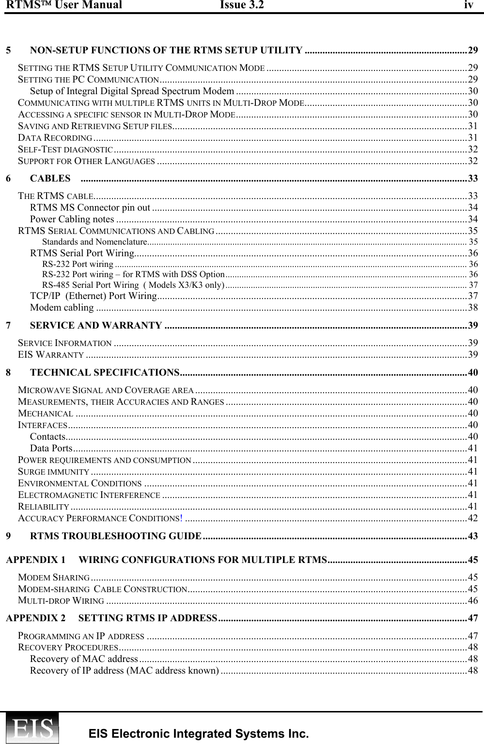

![RTMS User Manual Issue 3.2 32 EIS Electronic Integrated Systems Inc. RTMS STAT. MESSAGES ZONE: 1 2 3 4 5 6 7 8 SPEED IN Km/h. Occupancy 6 ft loop normalized. 11 03 2003 19:32:02 MESSAGE NO. 6 VOLUME: 5 8 19 17 6 9 11 16 LONG VEH: 0 0 0 0 1 2 2 0 STATION ID. 8 OCCUPANCY: 5 7 18 13 8 14 15 13 MID SIZE: 1 0 1 0 0 0 1 1 XLONG VEH: 0 0 0 0 1 0 0 0 FWDLK SPEED ? SIDEFRD SPD: 81 102 124 112 77 103 128 125 Dir. 128 V. 125 H. 80 11 03 2003 19:32:32 MESSAGE NO. 7 VOLUME: 6 8 10 11 11 12 14 17 LONG VEH: 0 0 0 0 0 3 2 0 STATION ID. 8 OCCUPANCY: 4 7 8 8 9 19 20 11 MID SIZE: 0 0 0 0 0 1 0 0 XLONG VEH: 0 0 0 0 0 0 1 0 FWDLK SPEED ? SIDEFRD SPD: 94 102 126 120 80 102 119 118 Dir. 128 V. 125 H. 80 11 03 2003 19:33:02 MESSAGE NO. 8 VOLUME: 6 7 16 12 6 11 11 13 LONG VEH: 0 0 0 0 0 0 0 0 STATION ID. 8 OCCUPANCY: 4 5 14 9 5 11 9 7 MID SIZE: 0 0 0 0 1 0 0 0 XLONG VEH: 0 0 0 0 0 0 0 0 FWDLK SPEED ? SIDEFRD SPD: 89 111 118 109 79 100 124 125 Dir. 128 V. 125 H. 80 Fig 18. Sample Recorded File Format Self-Test diagnostic The RTMS sensor can be tested any time to confirm that it is in working order. Select Self Test from the TOOLS window. The PC sends a Self-test command to the sensor. During the 20 seconds required by the RTMS to complete the test, a progress bar is displayed, ending with a display of the diagnostic results, including the RTMS firmware revision when the test is completed. Self-Test should be performed with the sensor monitoring real traffic. Support for Other Languages The RTMS Setup Utility program allows replacement of the default English button legends and menu labels to other languages. A Notepad file “Rtmslng.txt” (partially shown below), is included in the same folder with the “WinRtms.exe” program. Its default labels may be altered. To adapt the operation to your language, edit this text file, replacing English legends by text in your language, after “=” using a character set provided by your PC. Use character “&” to identify the next character as keyboard shortcut. [MainForm] FormTitle=RTMS Setup utility ver. MenuInfo=&Info MenuHelp=Press F1 for help ButtonMode=&MODE ButtonSensitivity=&SENSITIVITY ButtonZones=&ZONES ButtonFineTune=&FINETUNE ButtonPeriod=&PERIOD ButtonVerify=&VERIFY ButtonSpeedCalibration=SPEED &CALIB ButtonIDnumber=&ID NUMBER ButtonData=&DATA ButtonTools=&TOOLS ButtonAdvanced=&ADVANCED ButtonFile=FIL&E Power voltage (x 10), i.e. 12.5VDirection (Applicable to FwdLk mode, 0 =In, 128= Out ) Diagnostic byte. Consult EIS if second digit is not equal to “0”](https://usermanual.wiki/Image-Sensing-Systems/RTMS-X3/User-Guide-598984-Page-39.png)


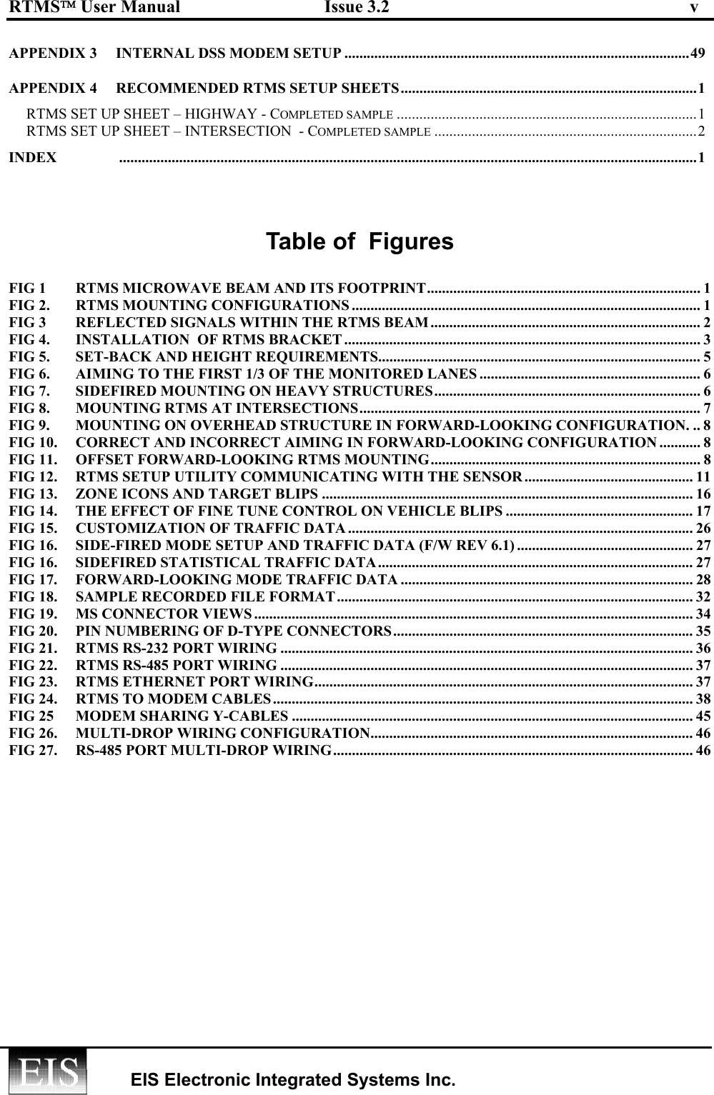
![RTMS User Manual Issue 3.2 1 EIS Electronic Integrated Systems Inc. APPENDIX 4 RECOMMENDED RTMS SETUP SHEETS RTMS SET UP SHEET – HIGHWAY - Completed sample RTMS ID # 1 NOTES 20 foot Median between Fast N and Fast S LOCATION Mile 15 Trucks in Slow N FINE TUNE -1 SENSITIVITY 5 SAVED FILE NAME May2002Mile15 When verifying counts a minimum of 50 vehicles must be counted BARRIER/TYPE YES / NO yes BETWEEN WHICH LANES Jersey barrier between 2 and 3. 7 foot shoulders ZONE 1 2 3 4 5 6 7 8 DIRECTION N N S S LANE (FAST MID SLOW) Slow Fast Fast Slow MANUAL COUNT 50 50 50 50 RTMS COUNT 51 48 49 51 % ERROR +2 -4 -2 +2 MESSAGE PERIOD 30 [SECS] POLL MODE (Y/N) Y TECH. INITIALS APPROVED](https://usermanual.wiki/Image-Sensing-Systems/RTMS-X3/User-Guide-598984-Page-58.png)