Image Sensing Systems SX300AN Autoscope RTMS SX-300 User Manual Autoscope Sx 300 User Guide
Image Sensing Systems, Inc. Autoscope RTMS SX-300 Autoscope Sx 300 User Guide
UserManual.wiki
>
Image Sensing Systems
>
SX300AN User Manual
User Manual
Navigation menu
Upload a User Manual
Namespaces
Wiki Guide
HTML
PDF
Info
Views
User Manual
Discussion / Help
Navigation

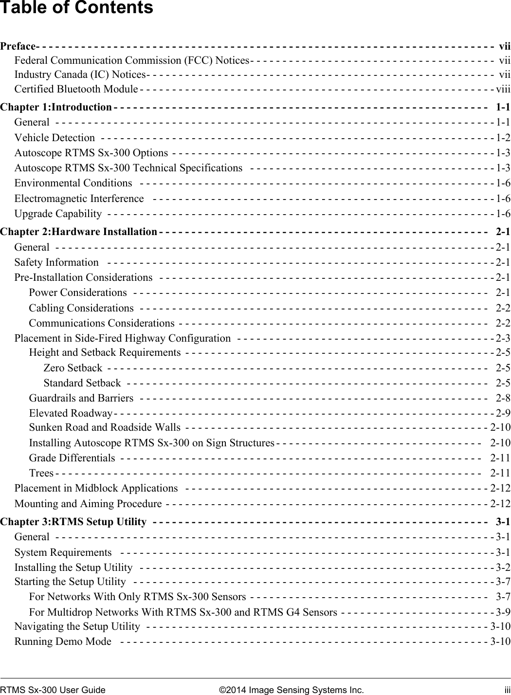


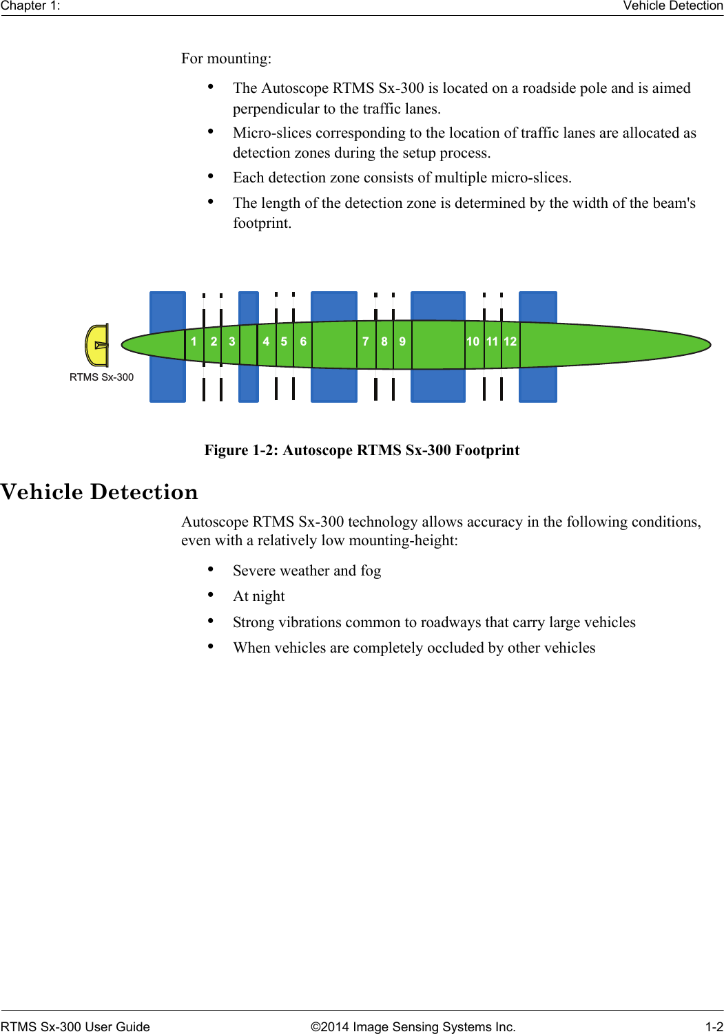
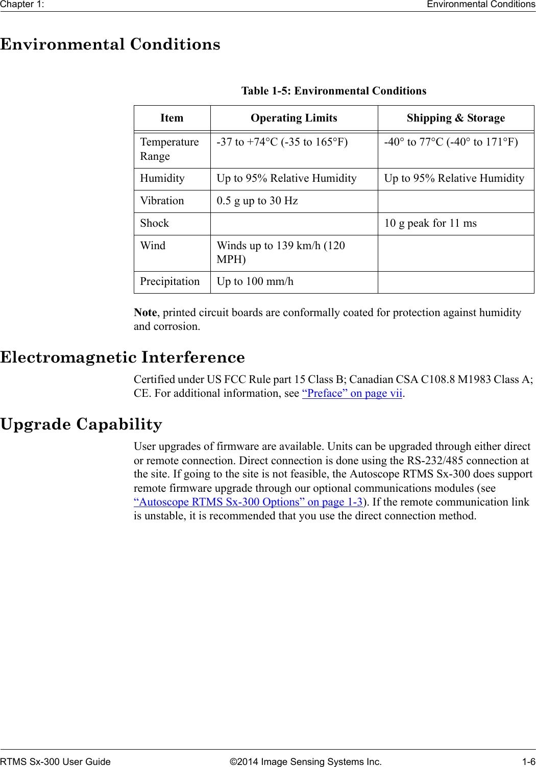

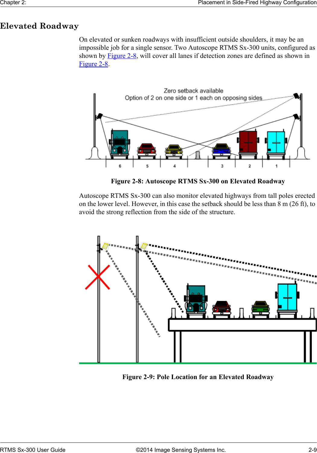
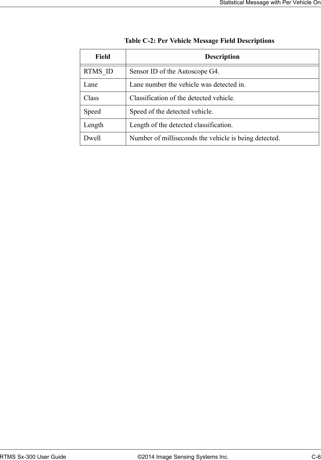
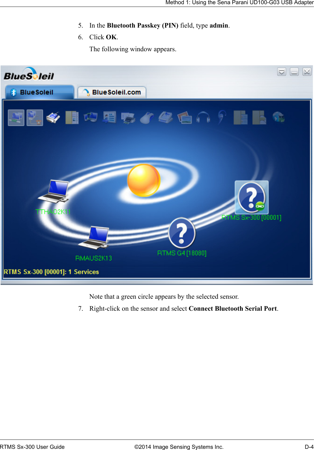
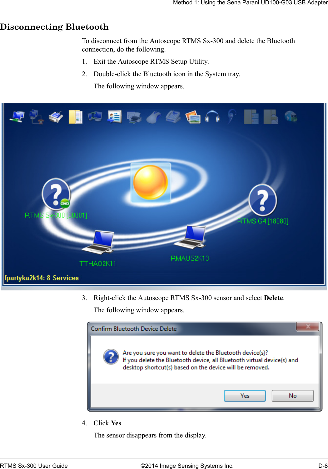
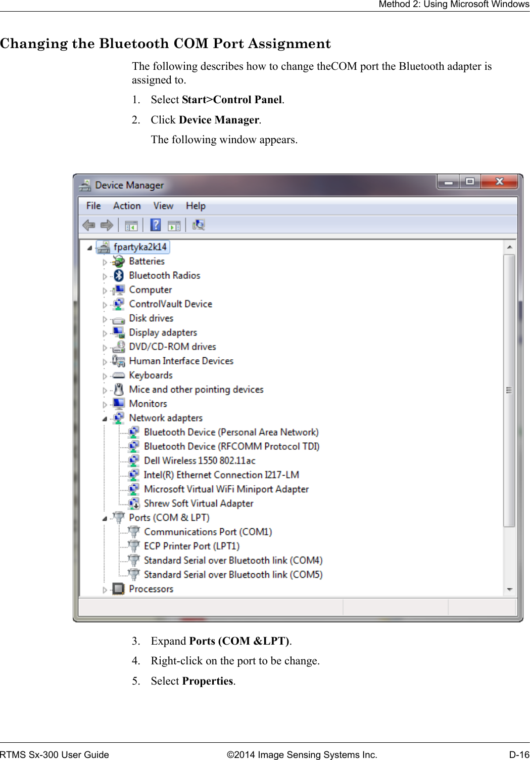
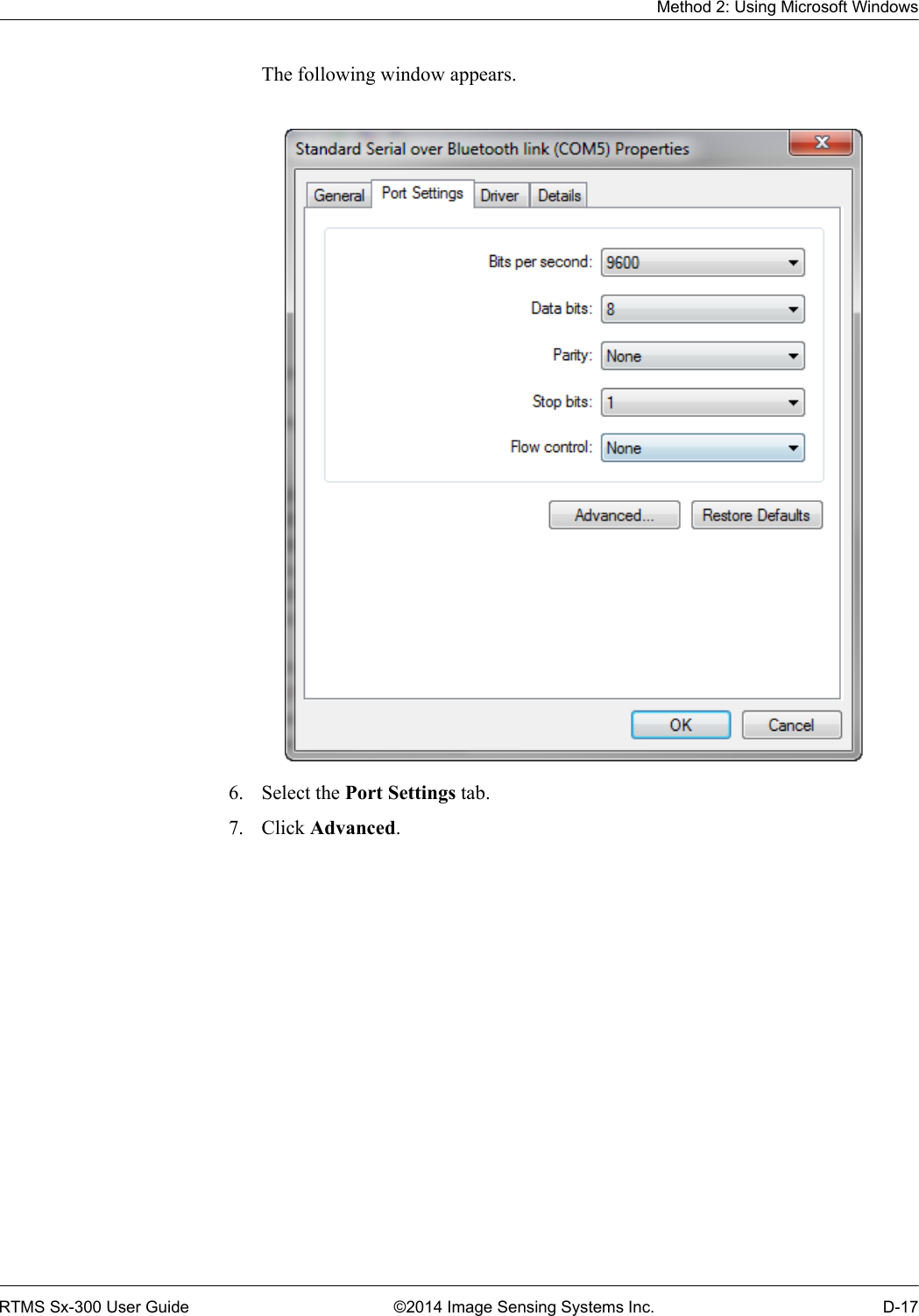
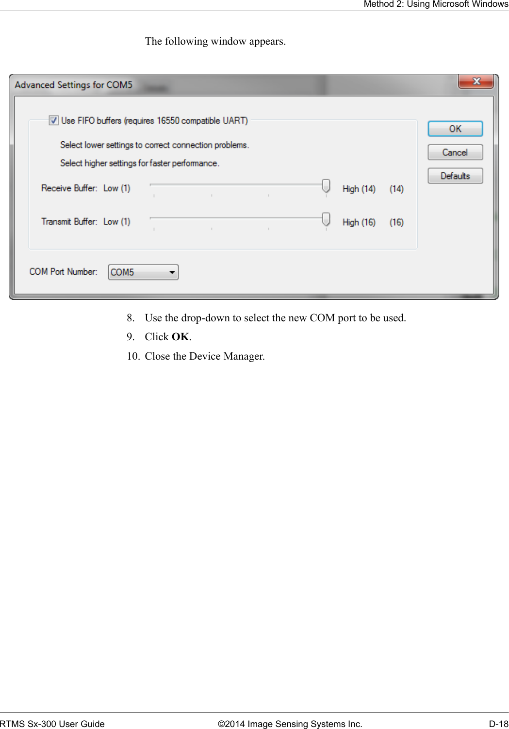
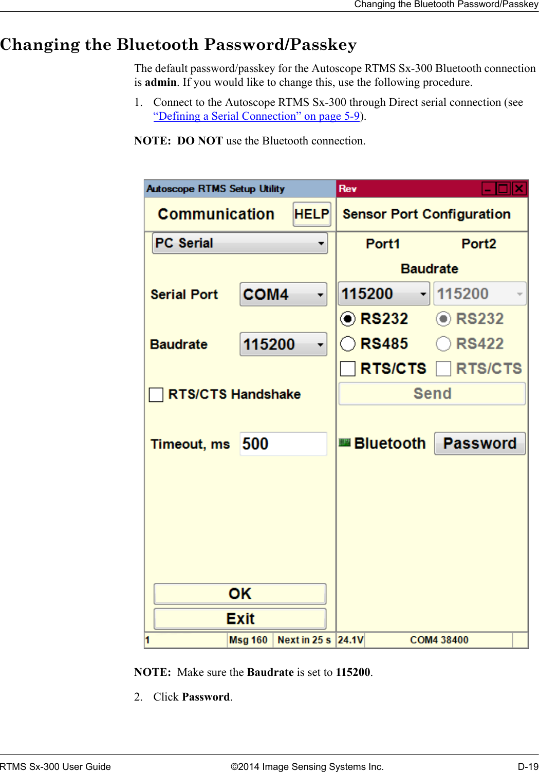
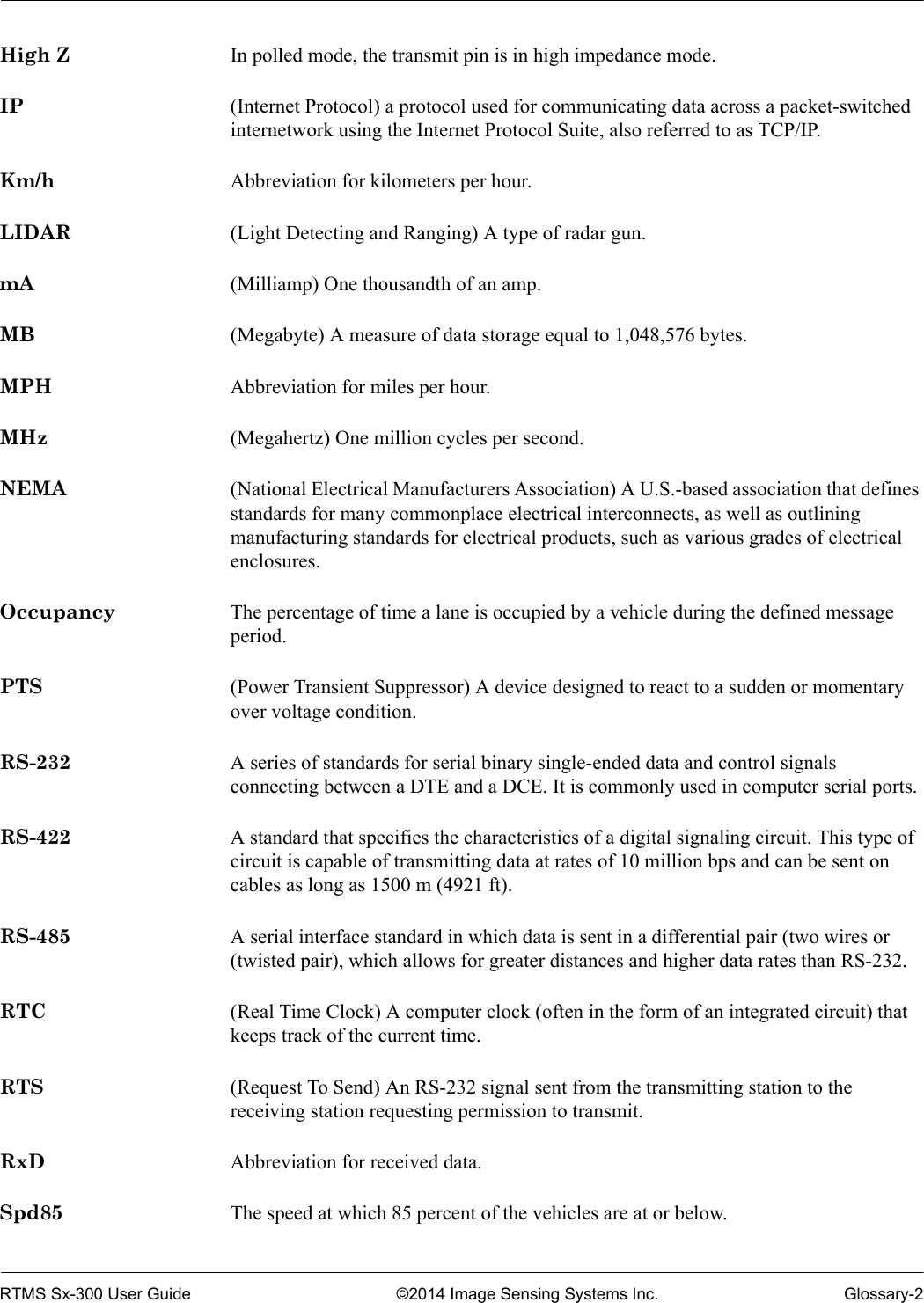
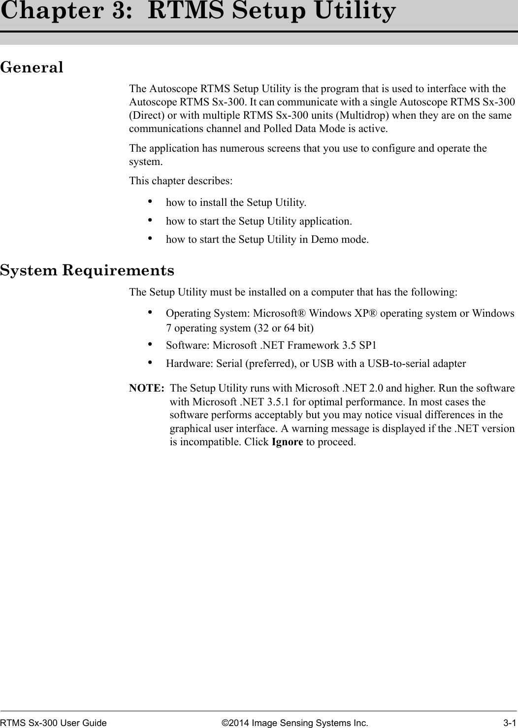
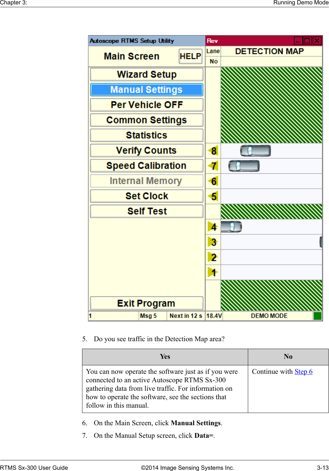
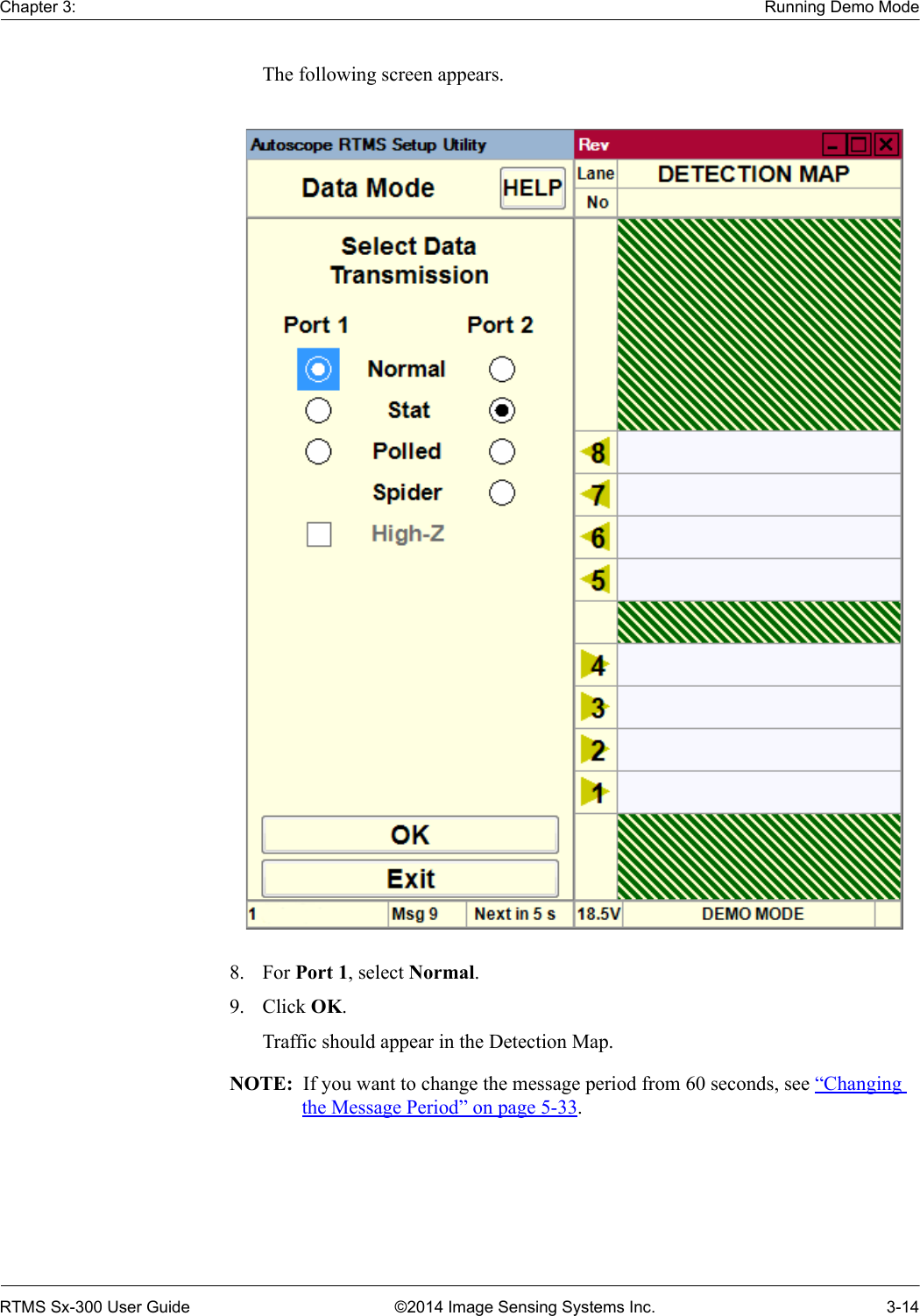
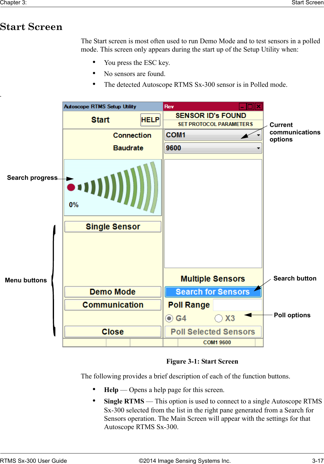
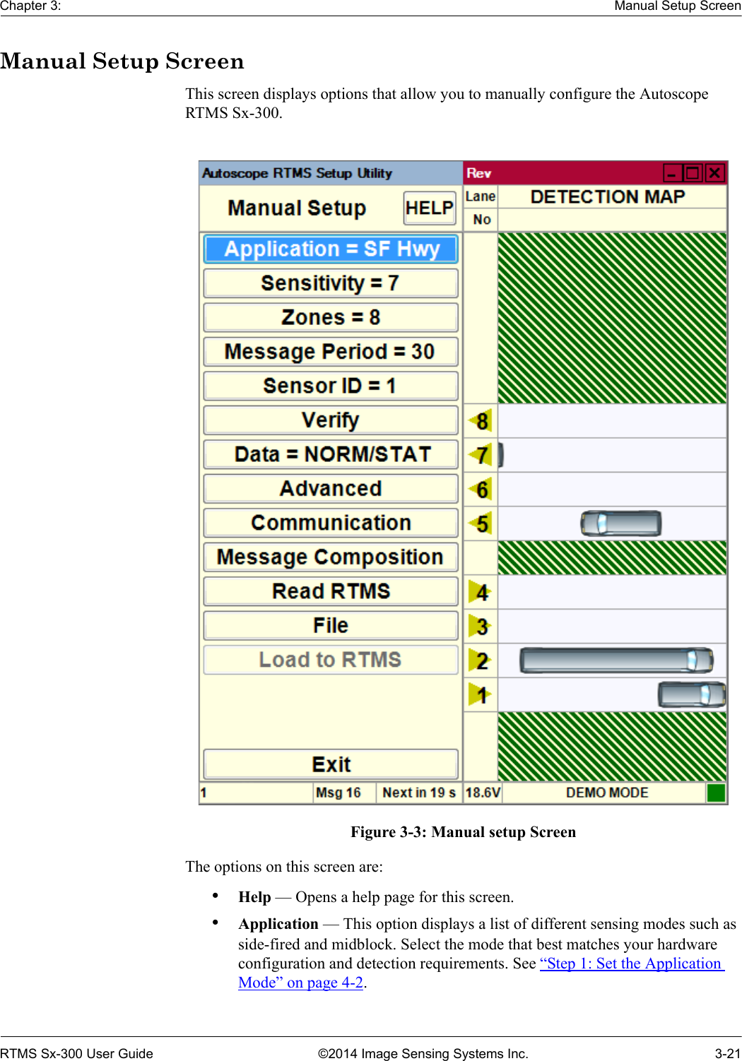
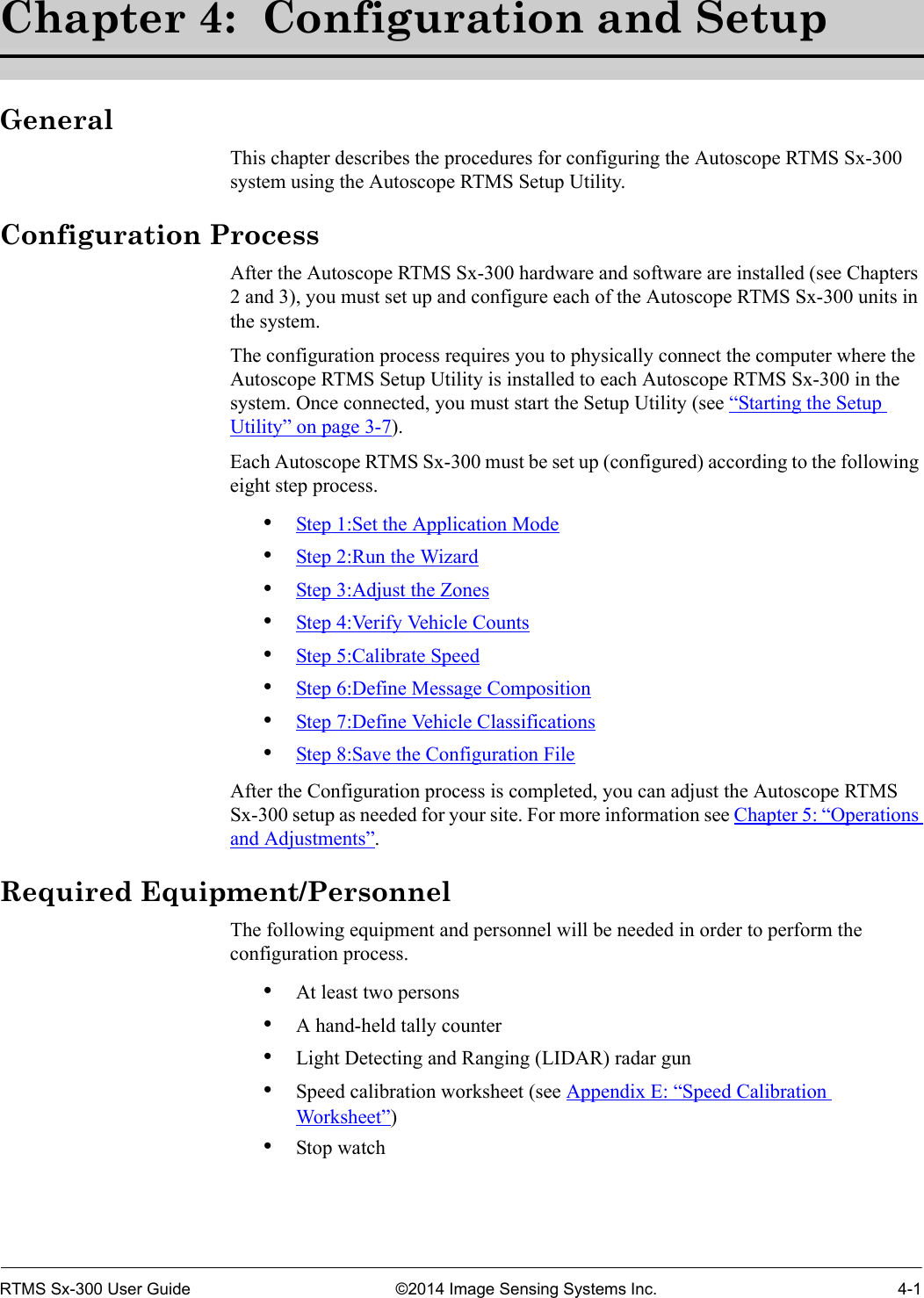
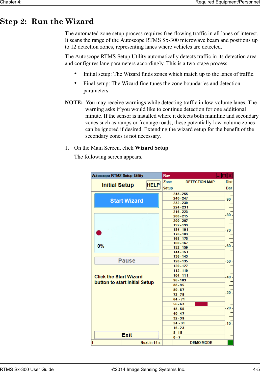
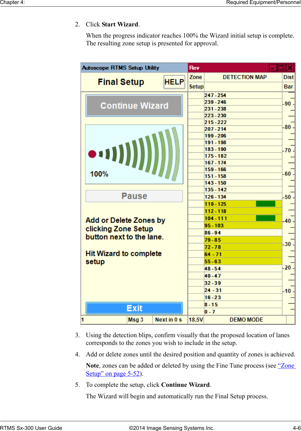
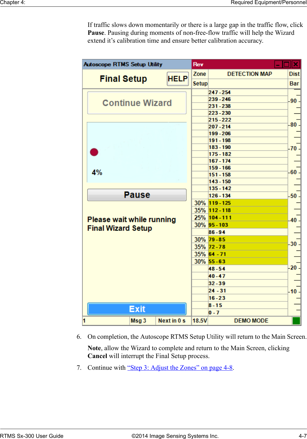
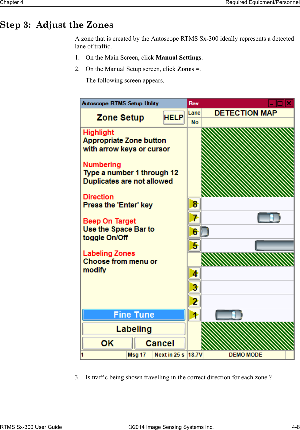
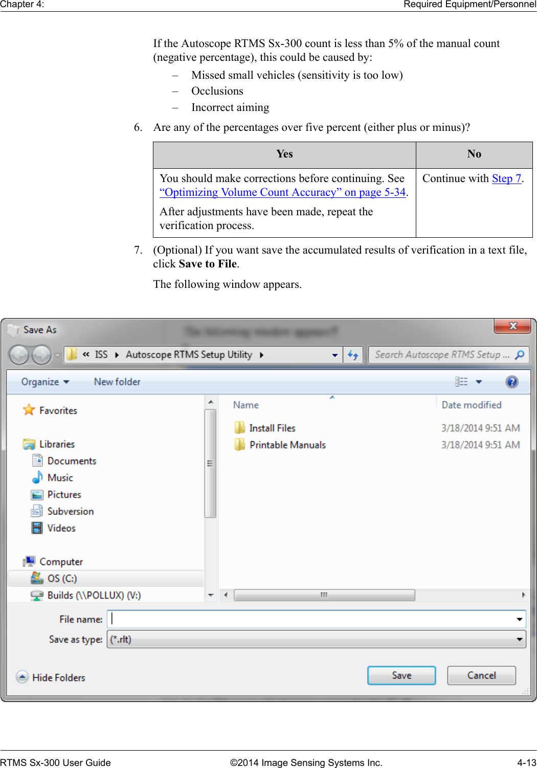
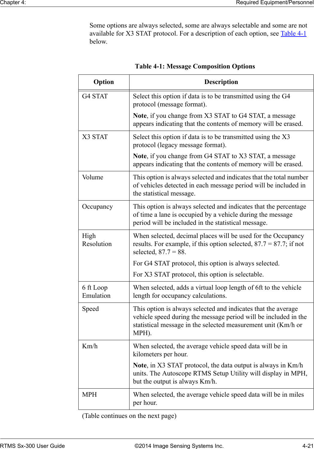
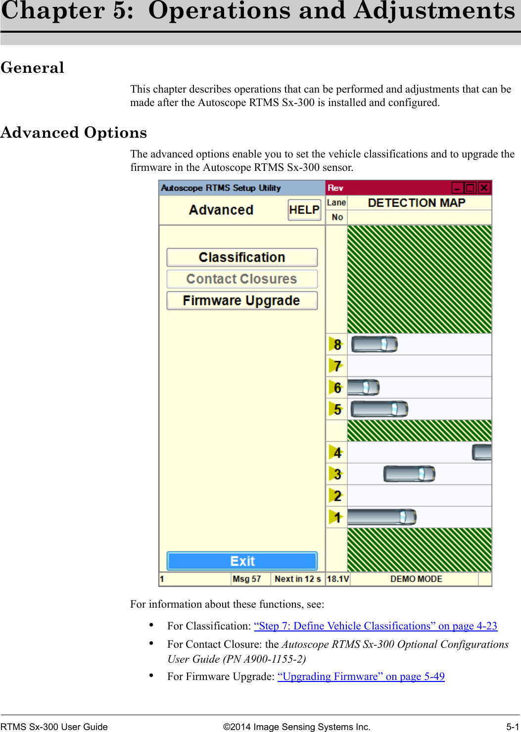
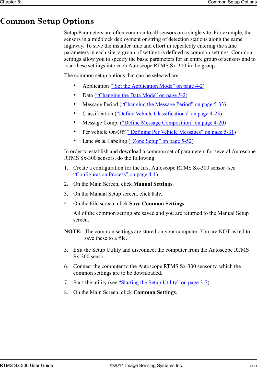
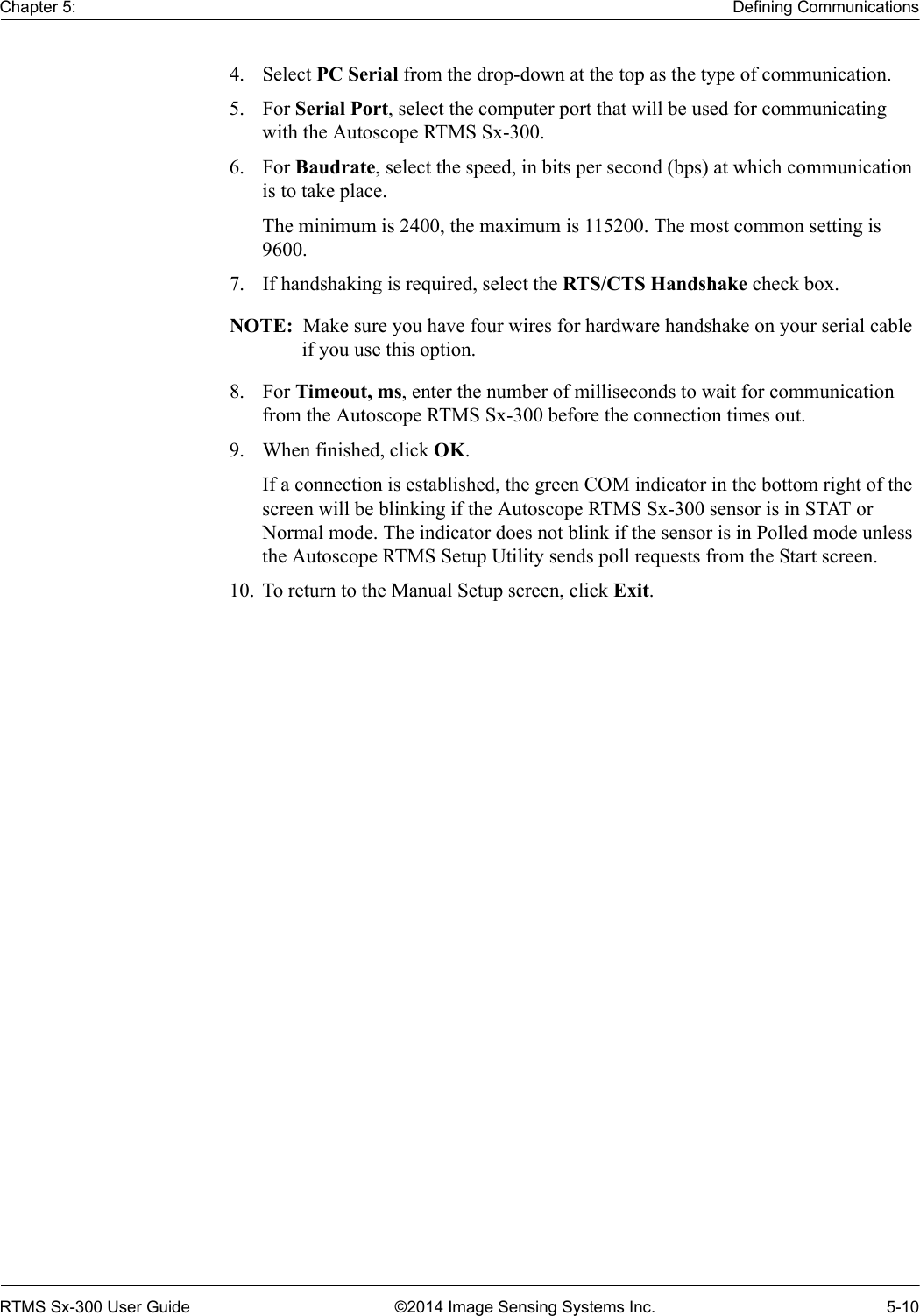
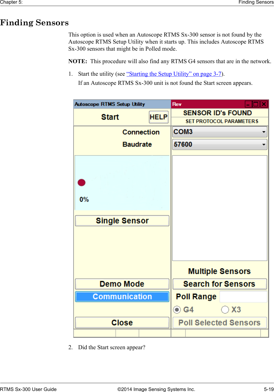
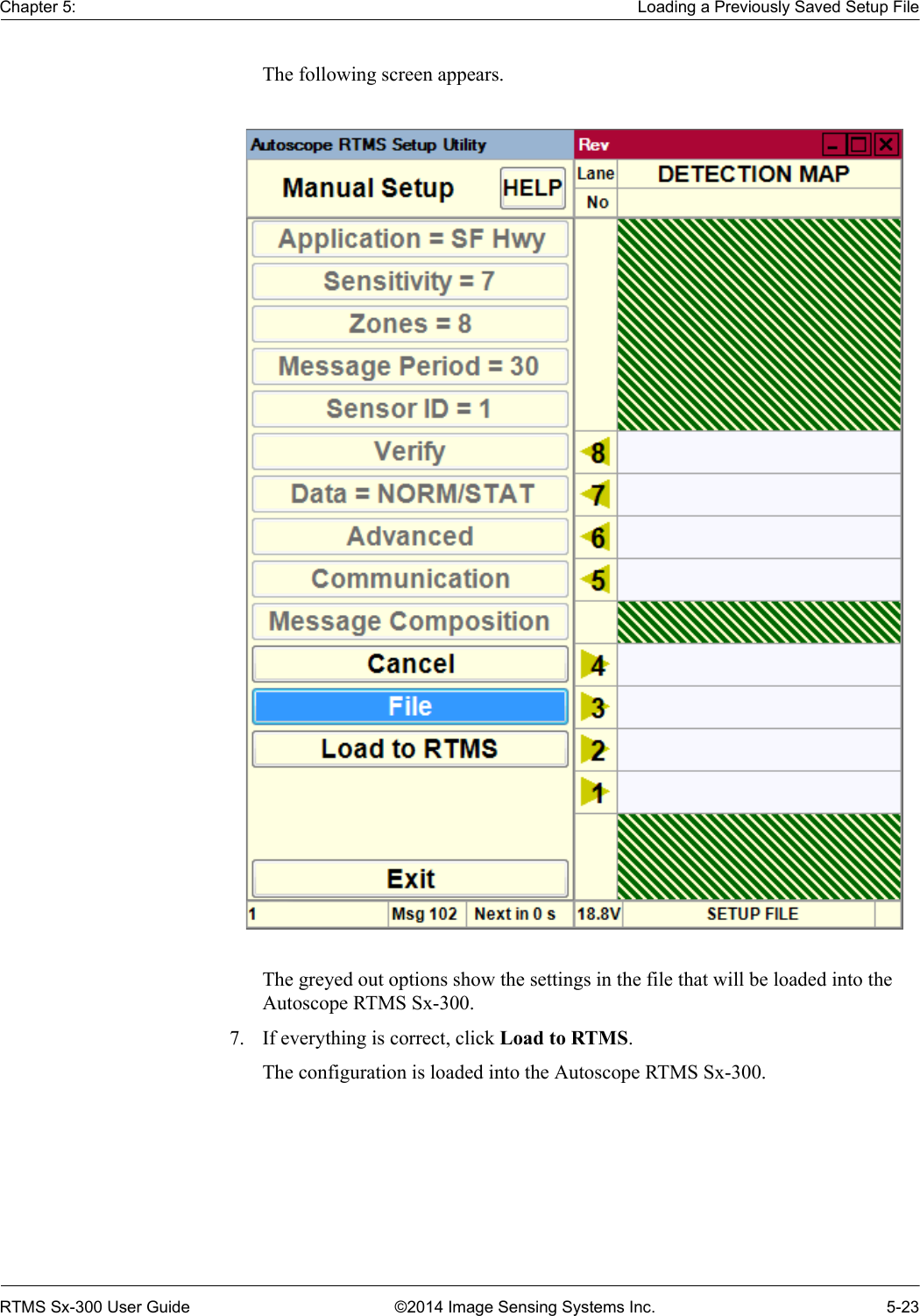
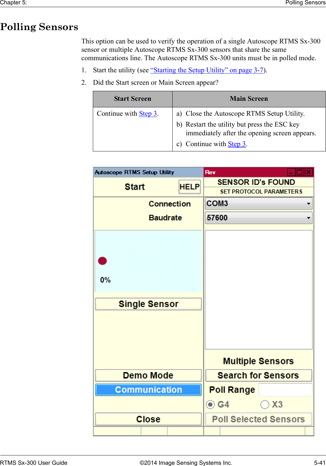
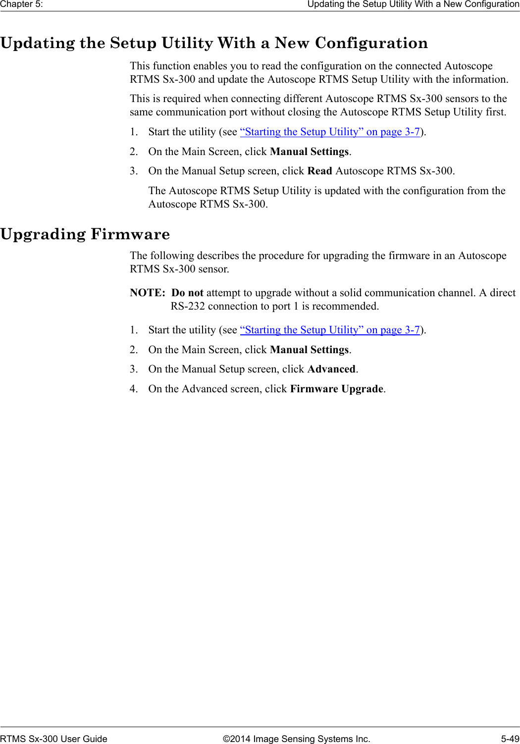
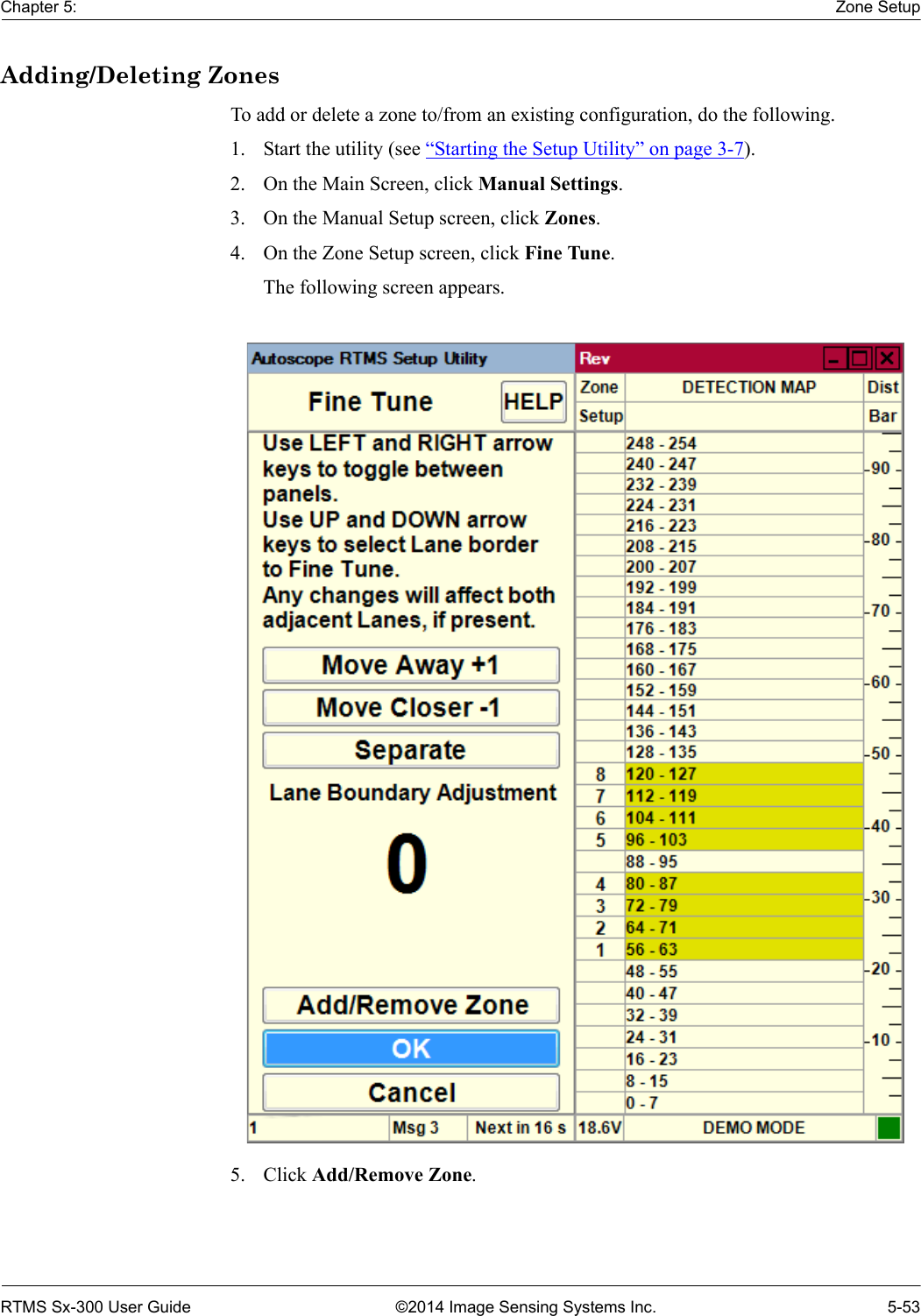
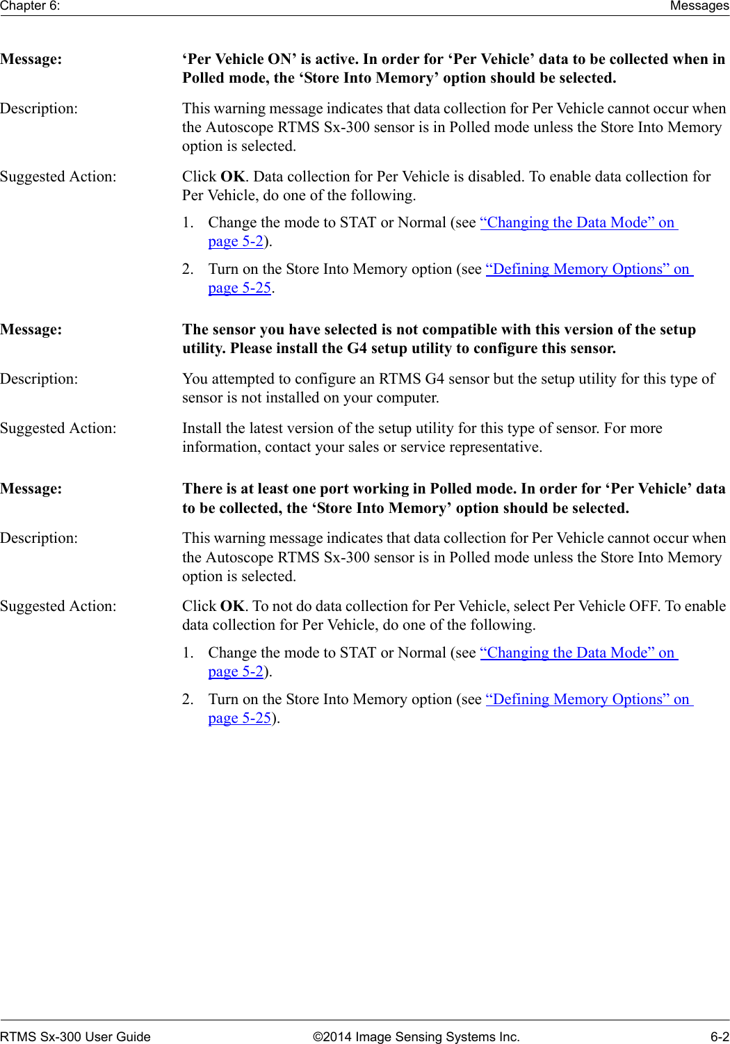
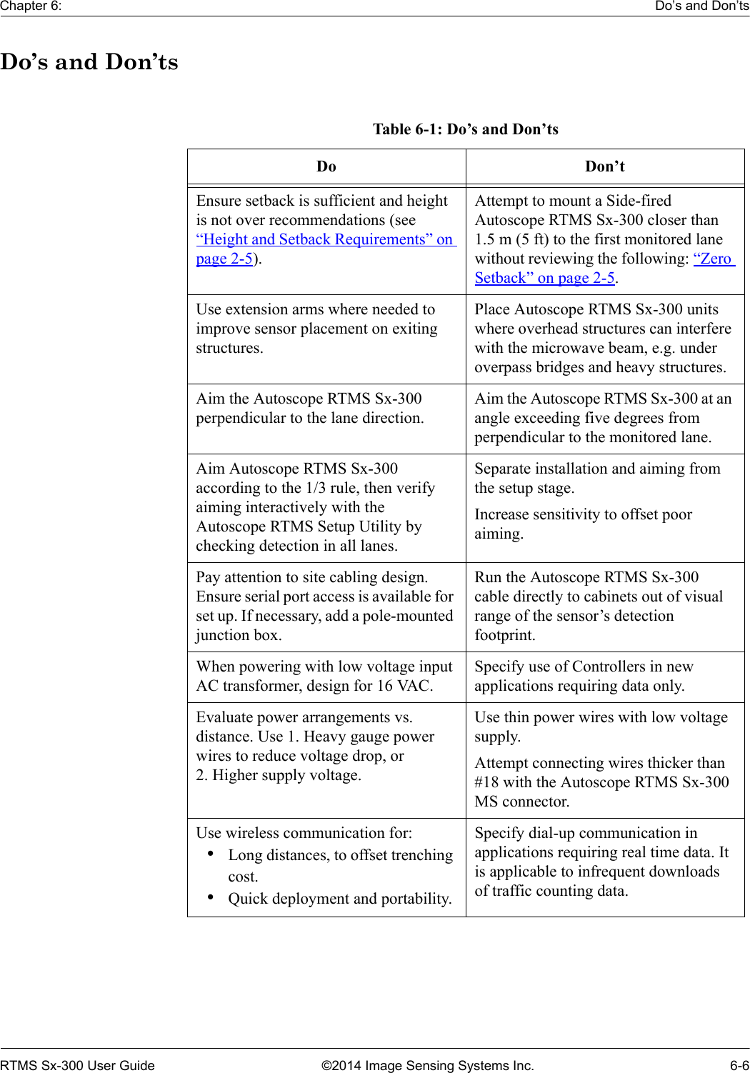
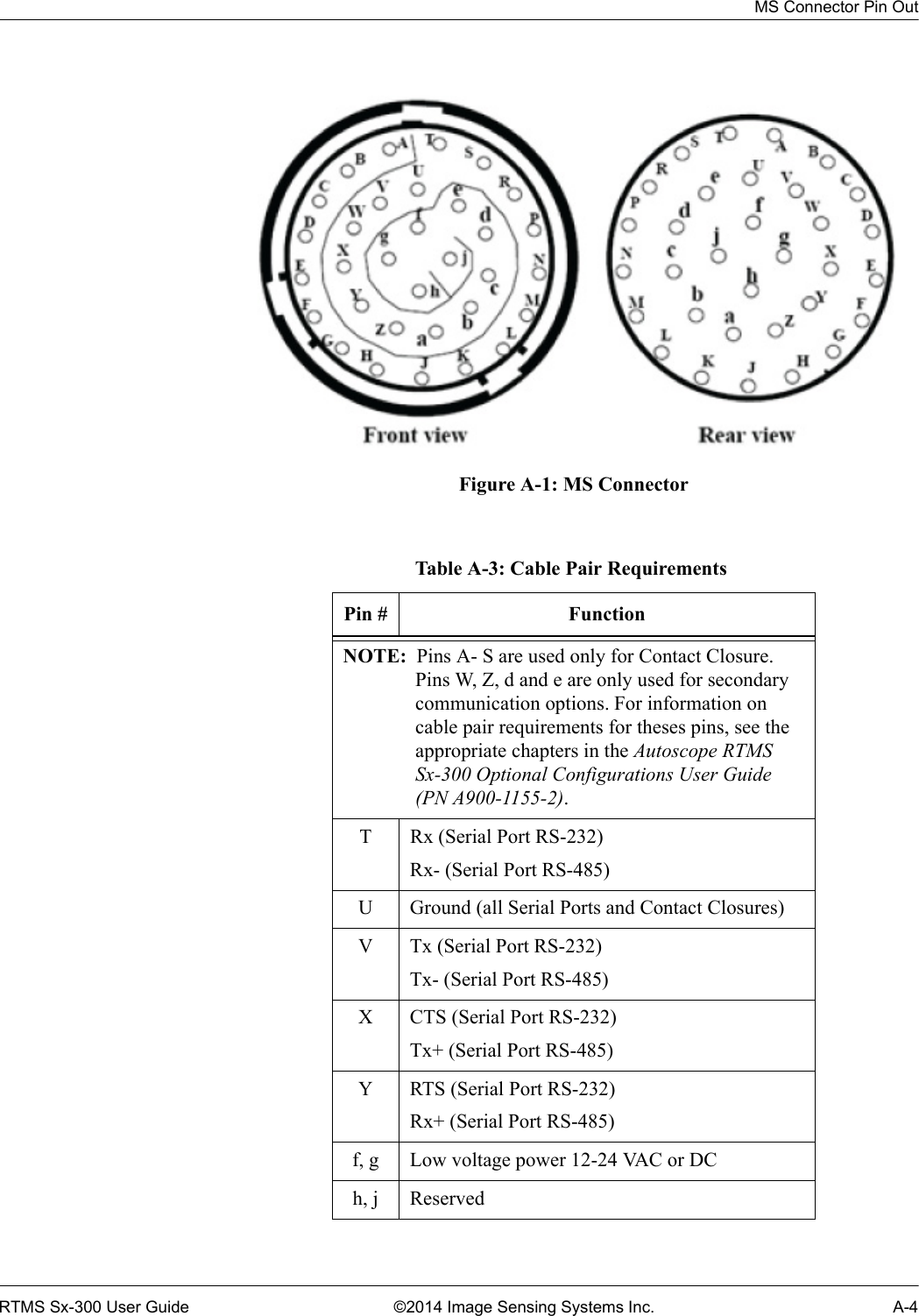
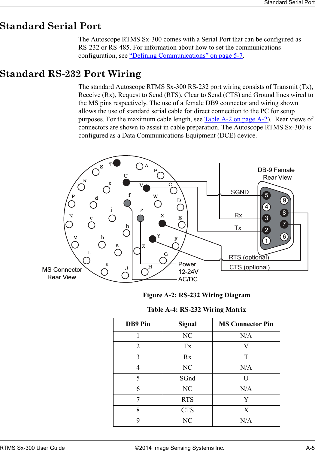
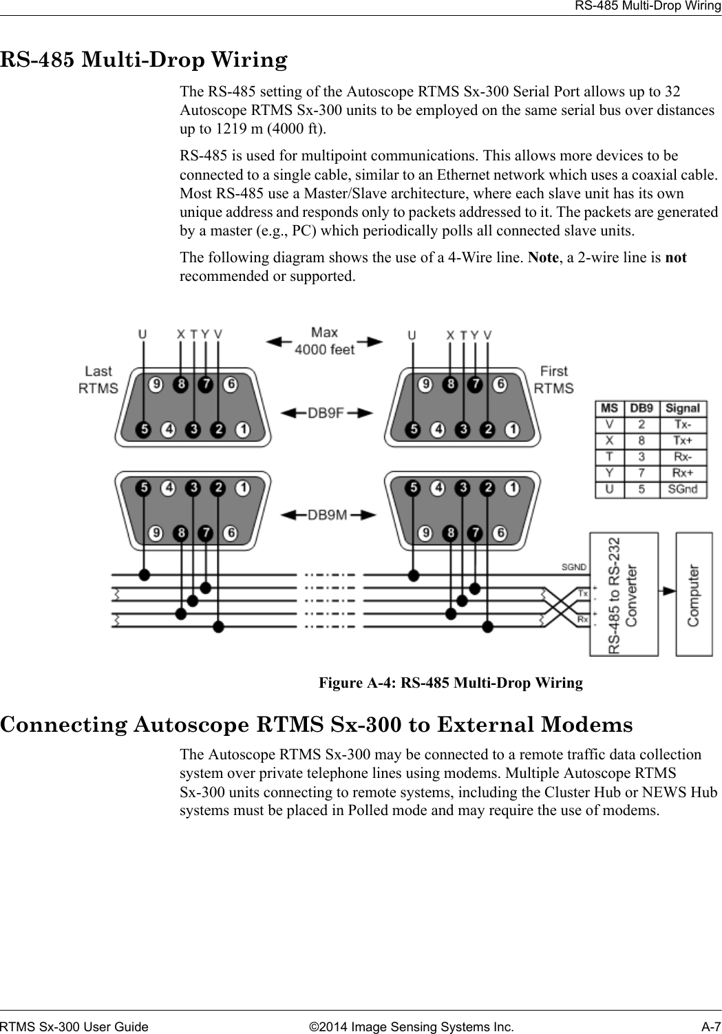
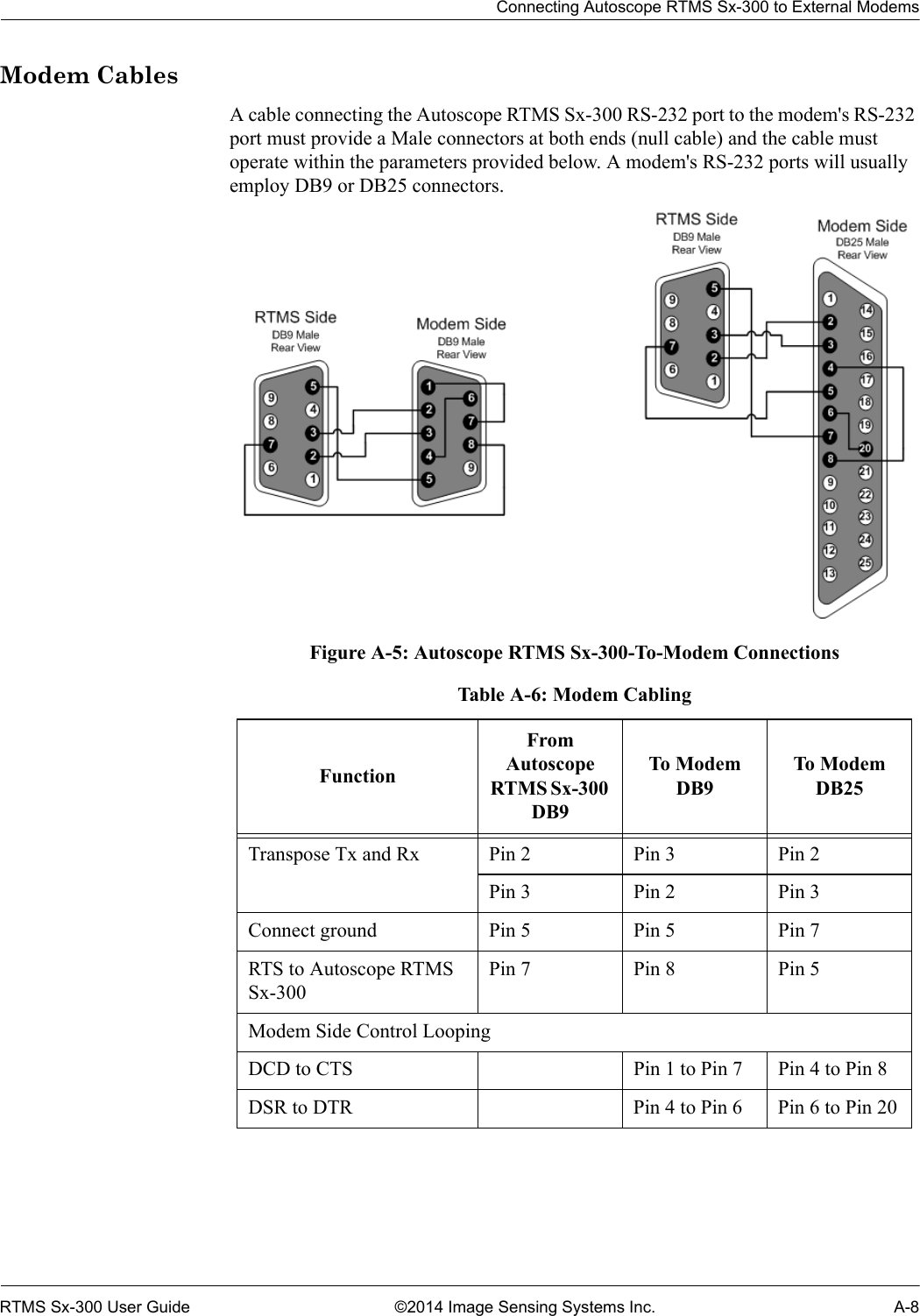
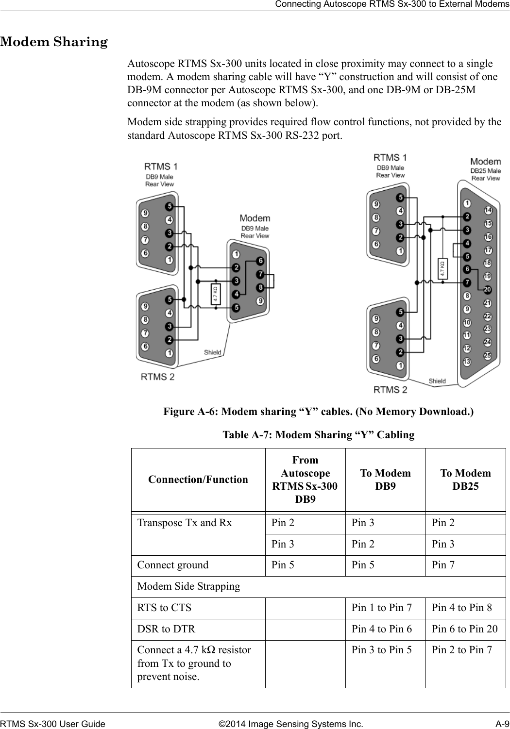
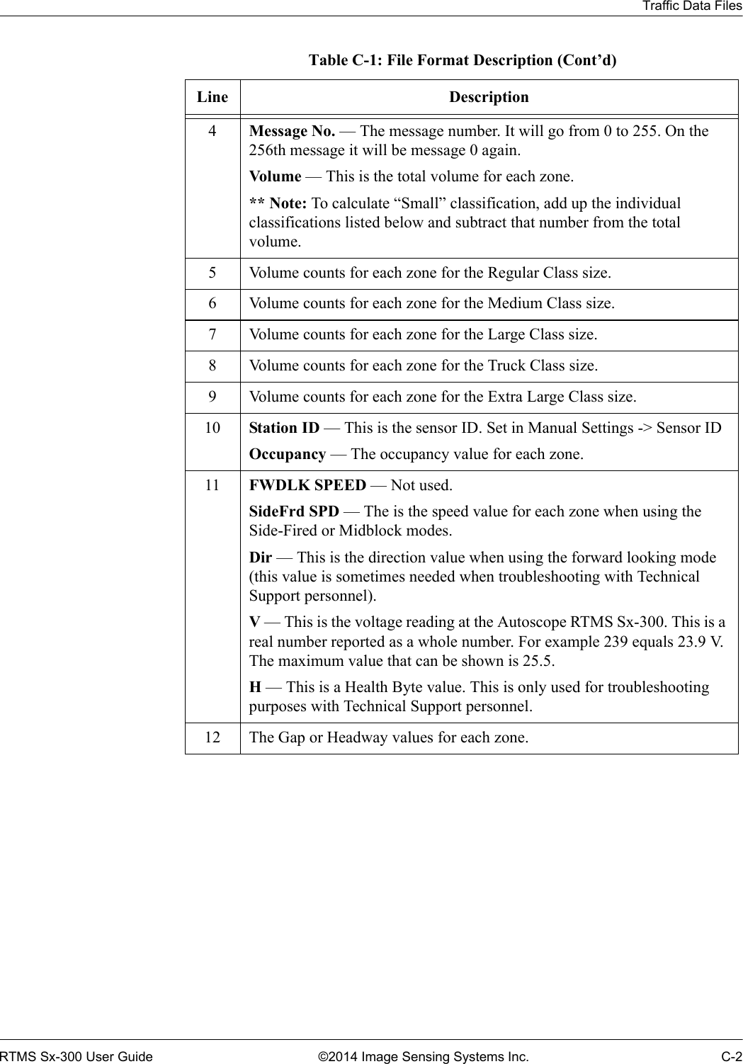
![Chapter 2: Placement in Side-Fired Highway ConfigurationRTMS Sx-300 User Guide ©2014 Image Sensing Systems Inc. 2-10Sunken Road and Roadside WallsWhen vertical surfaces reflecting microwaves (e.g., dense chain link fences or retaining walls of a sunken roadway) are present, multi-path reflections from large vehicles in close lanes cause additional false (ghost) detection in farther detection zones.Figure 2-10: False Target Generated by Fence Or WallTo avoid this problem install the Autoscope RTMS Sx-300 higher and increase the elevation angle to detect the far lanes of traffic excluding the nearest lanes, as shown on the right in Figure 2-10.Installing Autoscope RTMS Sx-300 on Sign StructuresThe installation of the Autoscope RTMS Sx-300 on Message Sign structures is acceptable only if the Autoscope RTMS Sx-300 is mounted to be offset from the overhead span of the structure. Structures can reflect the microwave signal and distort the accuracy of detection. Some structures such as DMS units have very wide, flat metal bottoms to the structure that are similar in nature to bridges, these type can cause more interference than other lattice work type structures and may require consultation with Autoscope RTMS Sx-300 Technical Support.The best way to mount the Autoscope RTMS Sx-300 is to place a horizontal mast arm or pipe approximately 1.3 m (4 ft) away from the structure (1.8-2.4 m [6-8 ft] if DMS), ideally on the back of the structure away from any lighting or signs. Ensure the detector is aimed perpendicular to the traffic flow.Figure 2-11: Autoscope RTMS Sx-300 on Sign Structures](https://usermanual.wiki/Image-Sensing-Systems/SX300AN/User-Guide-2271723-Page-24.png)
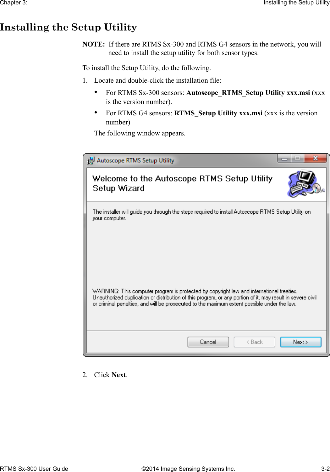
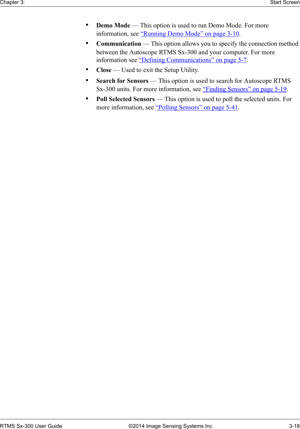
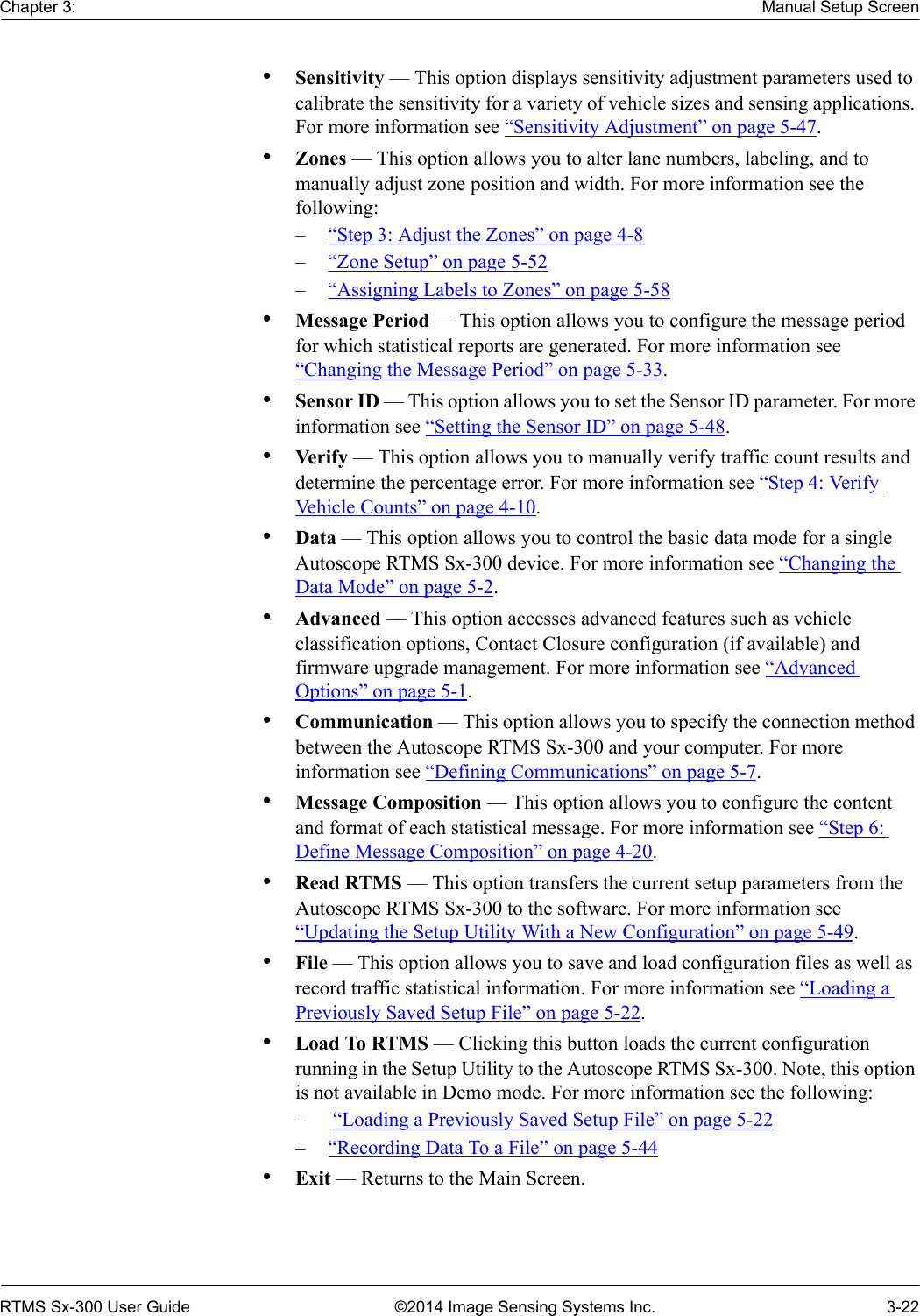
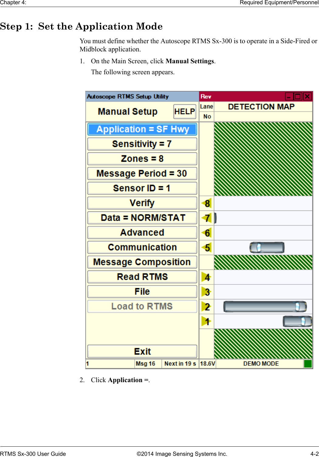
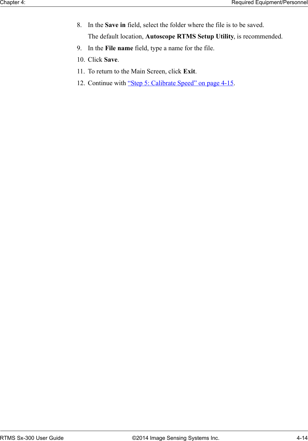
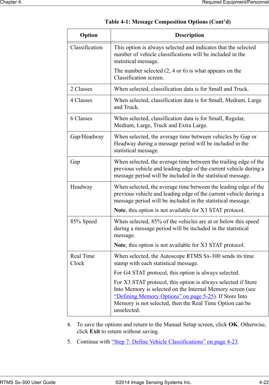
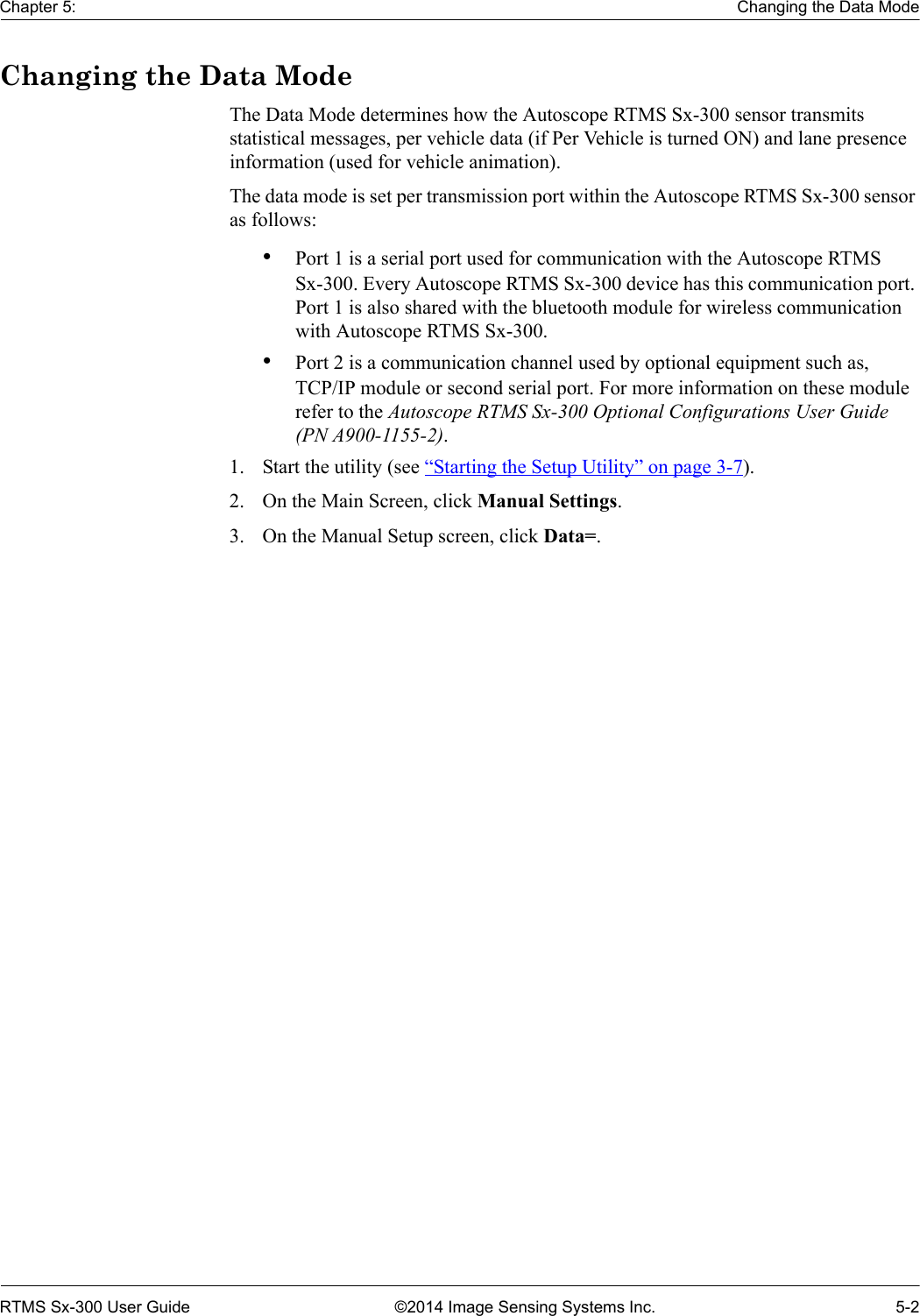

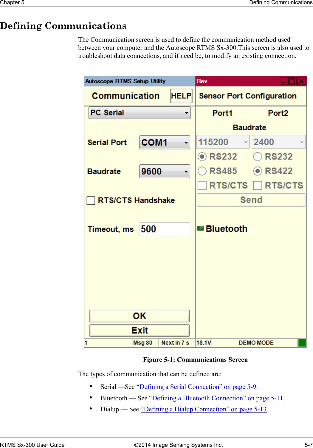
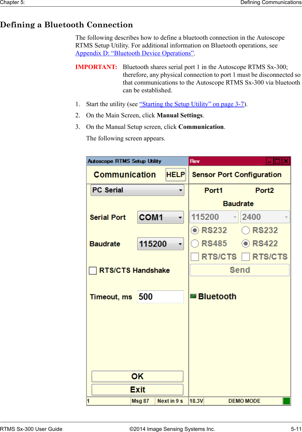

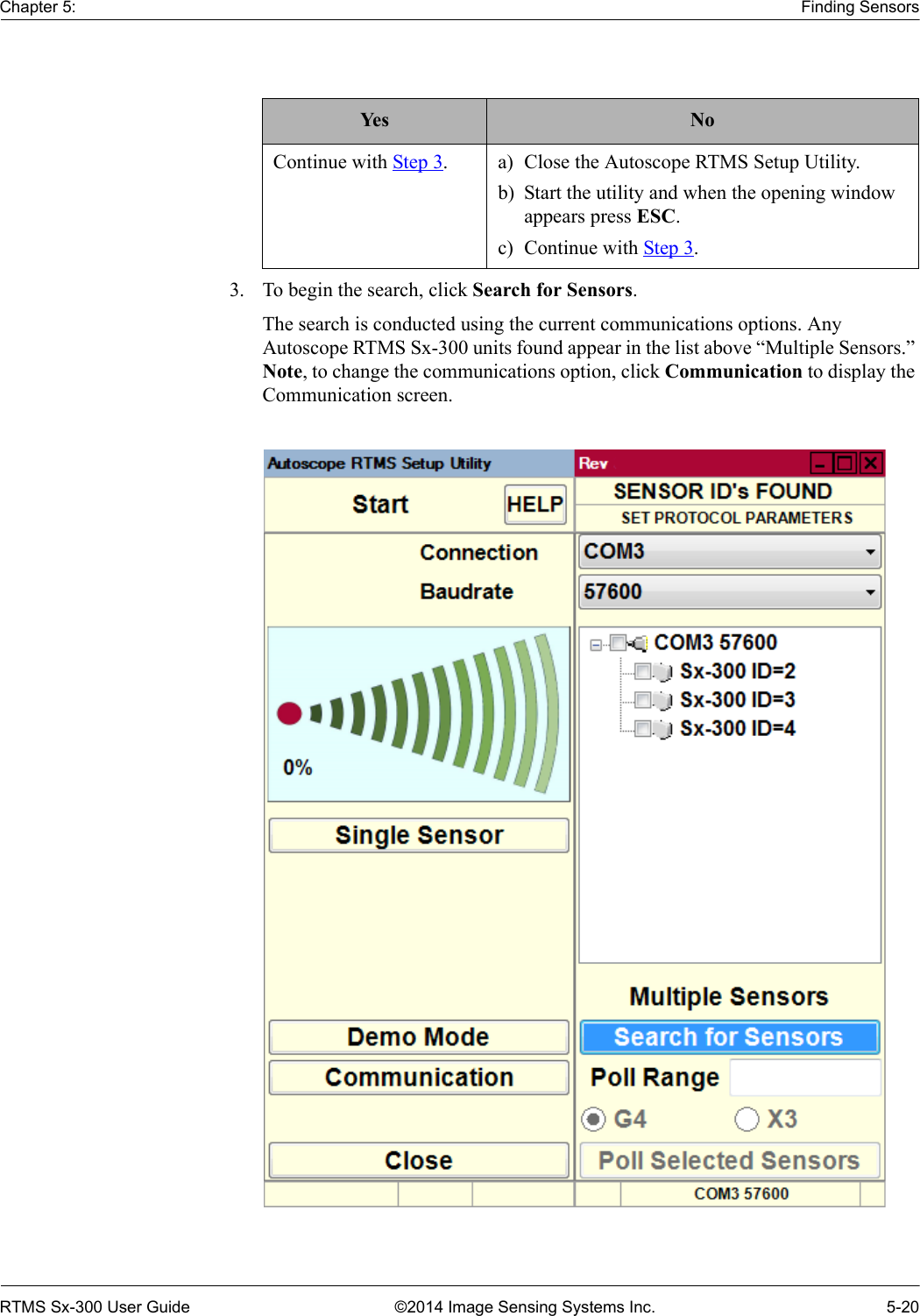
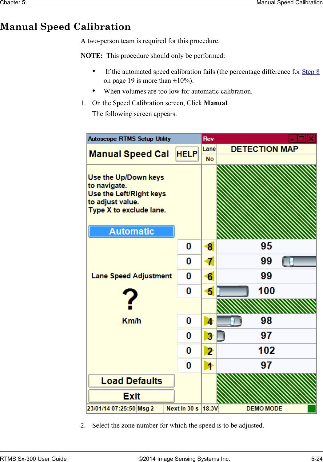


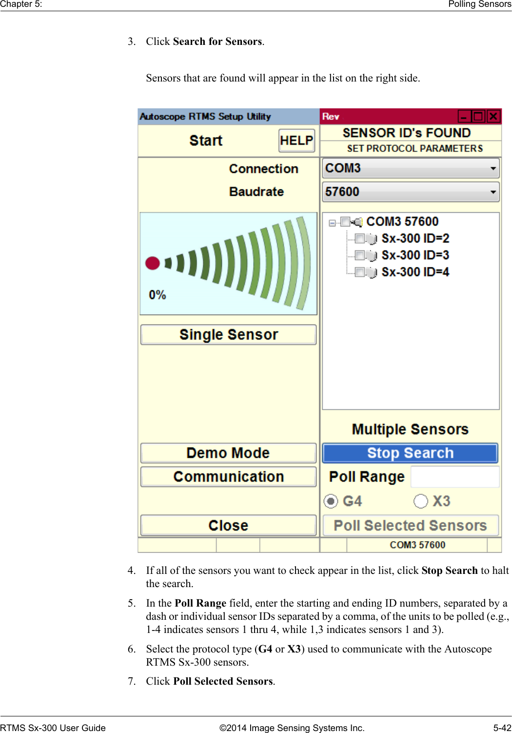
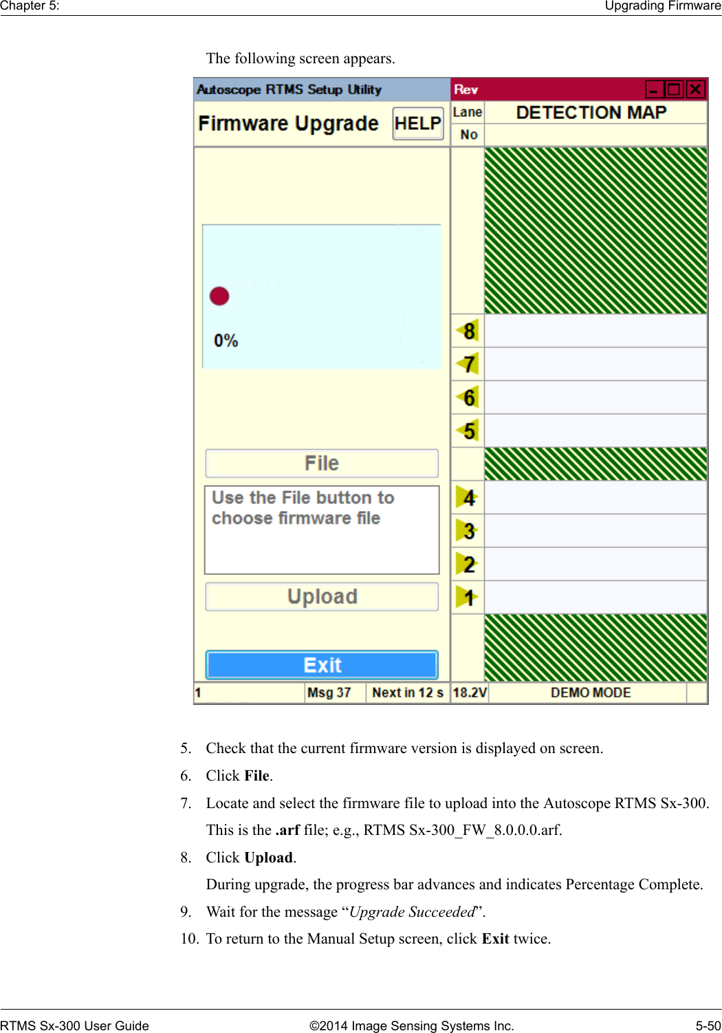
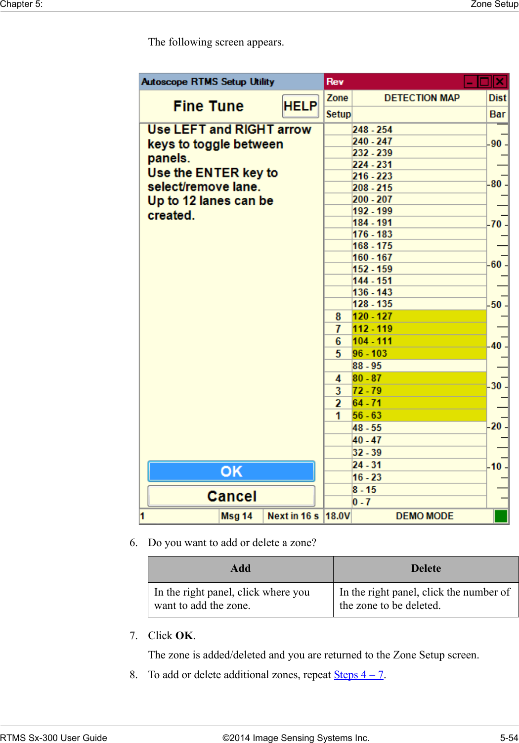
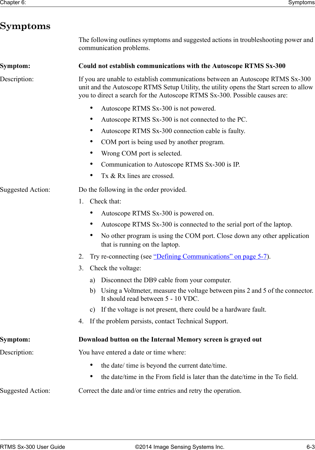

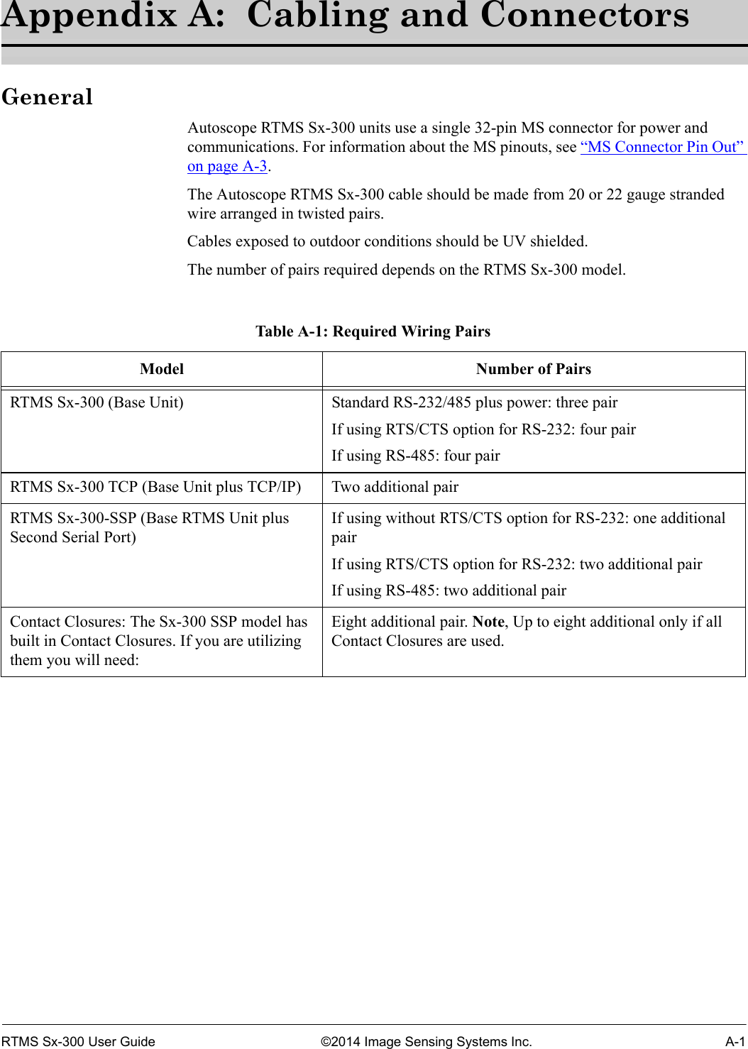
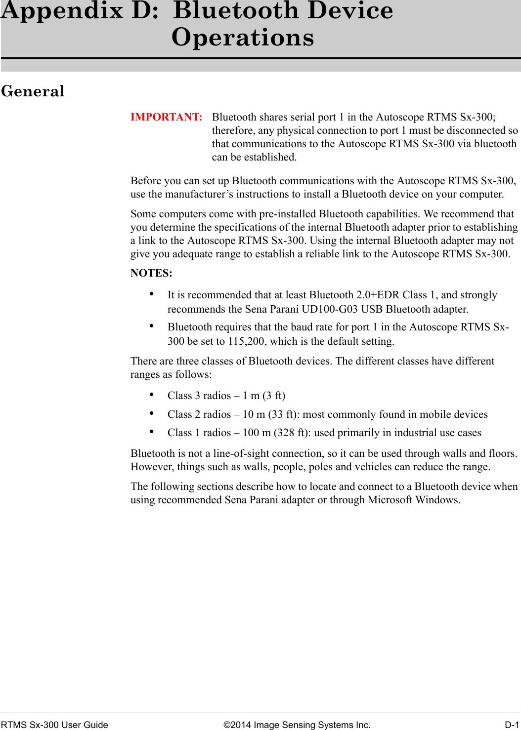
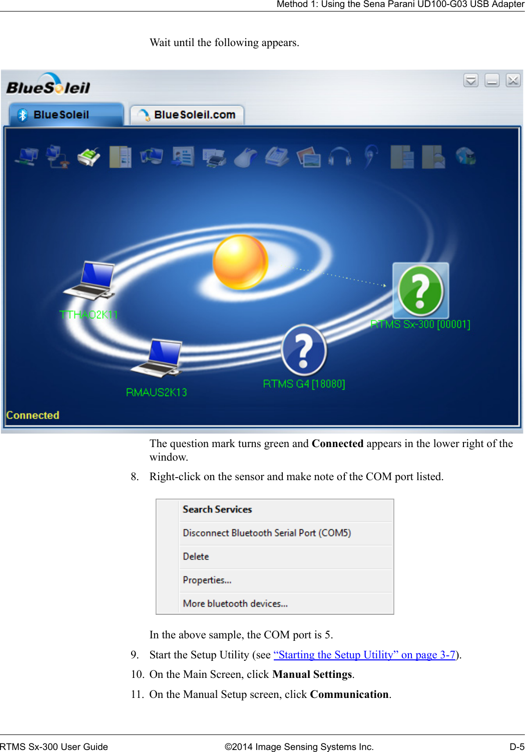
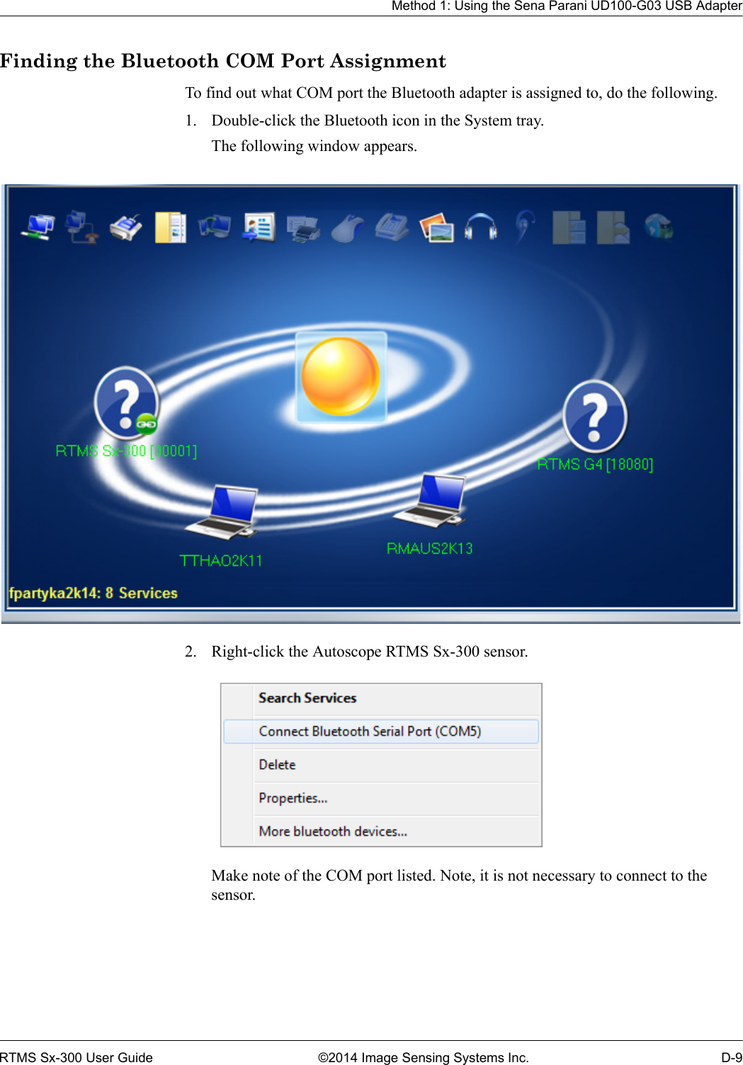
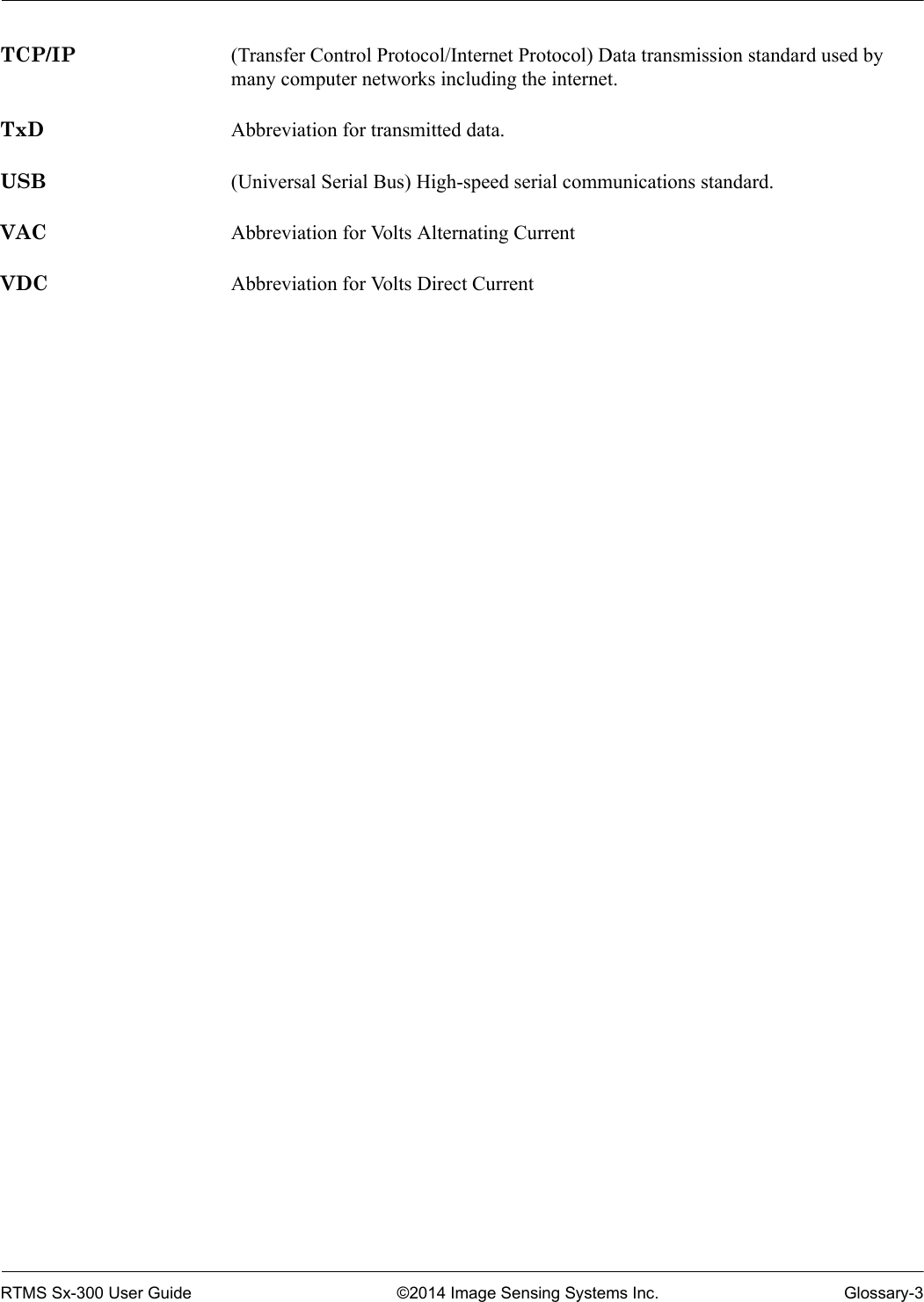
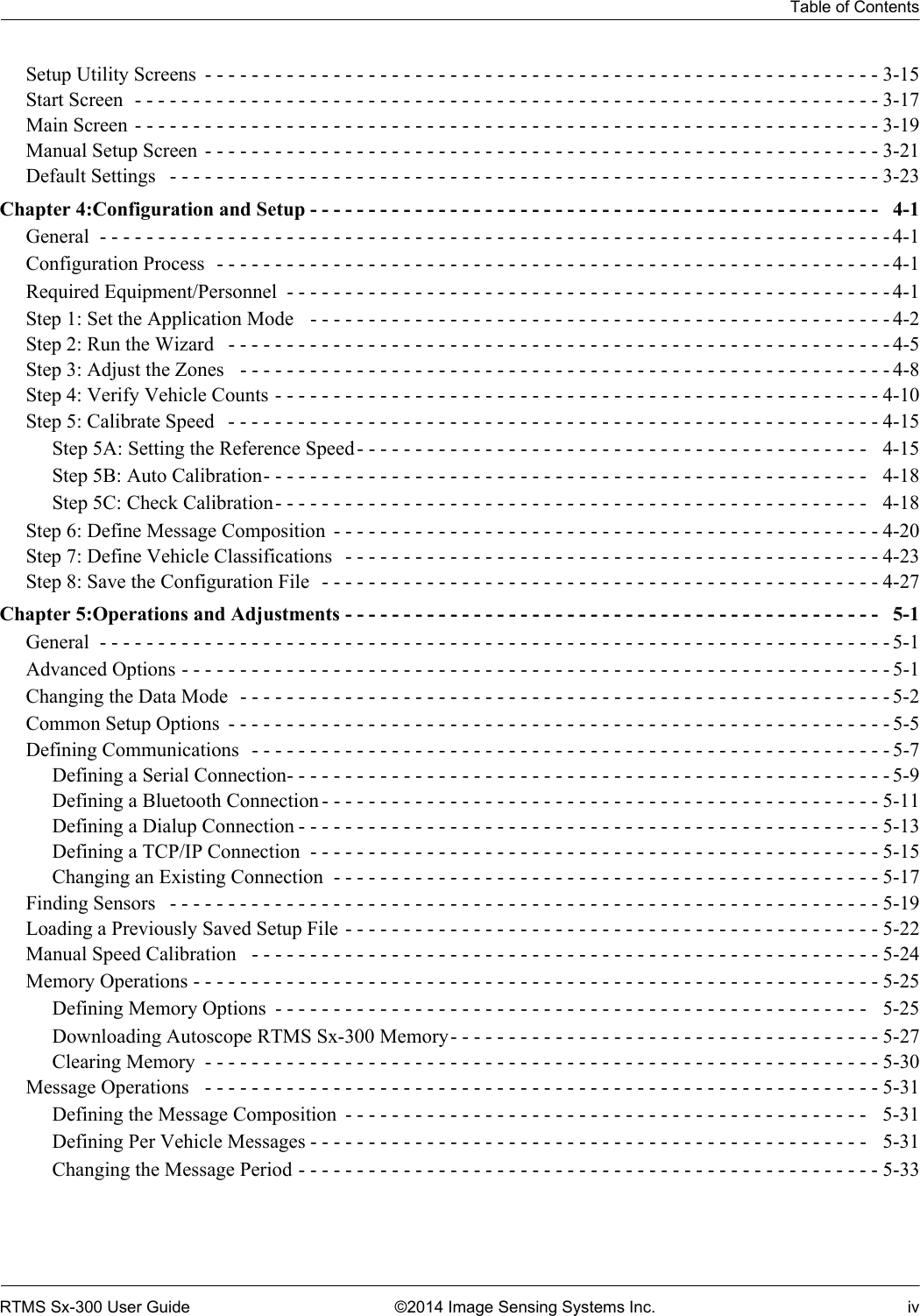
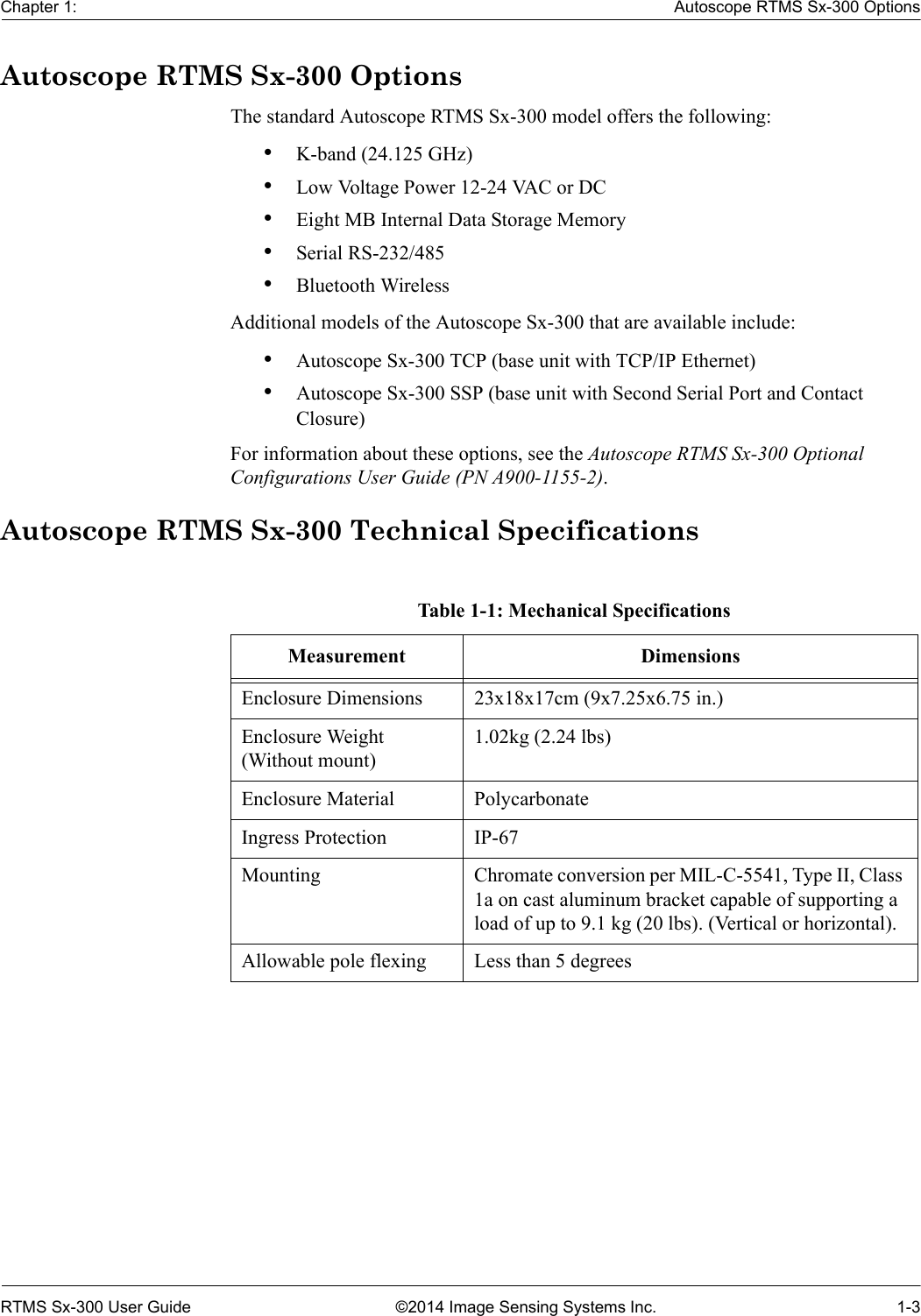
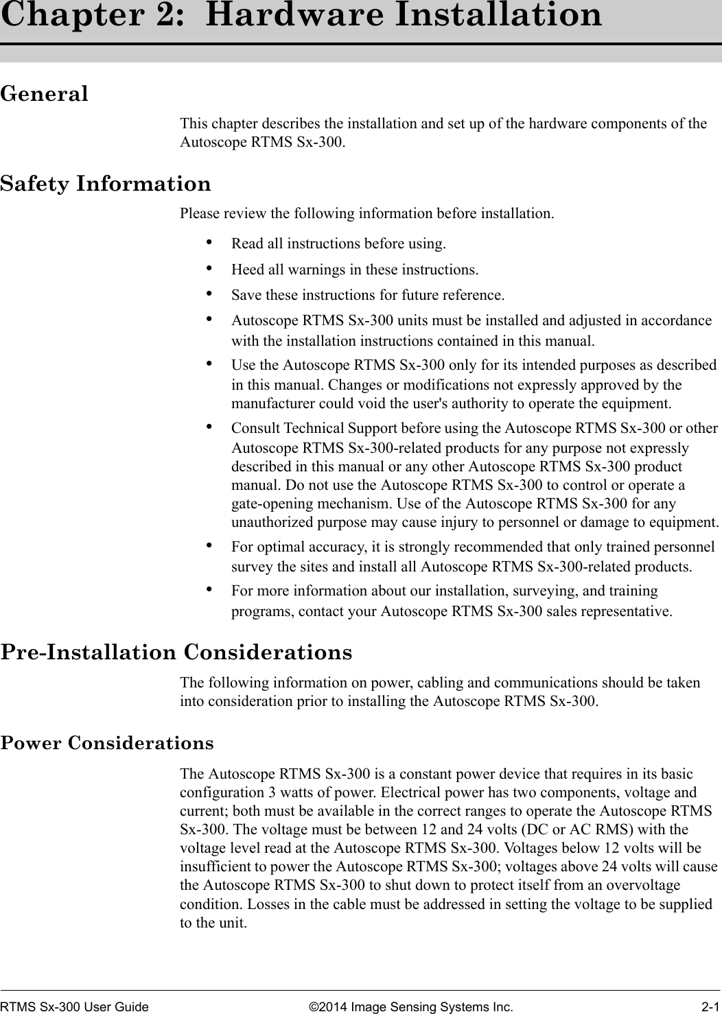
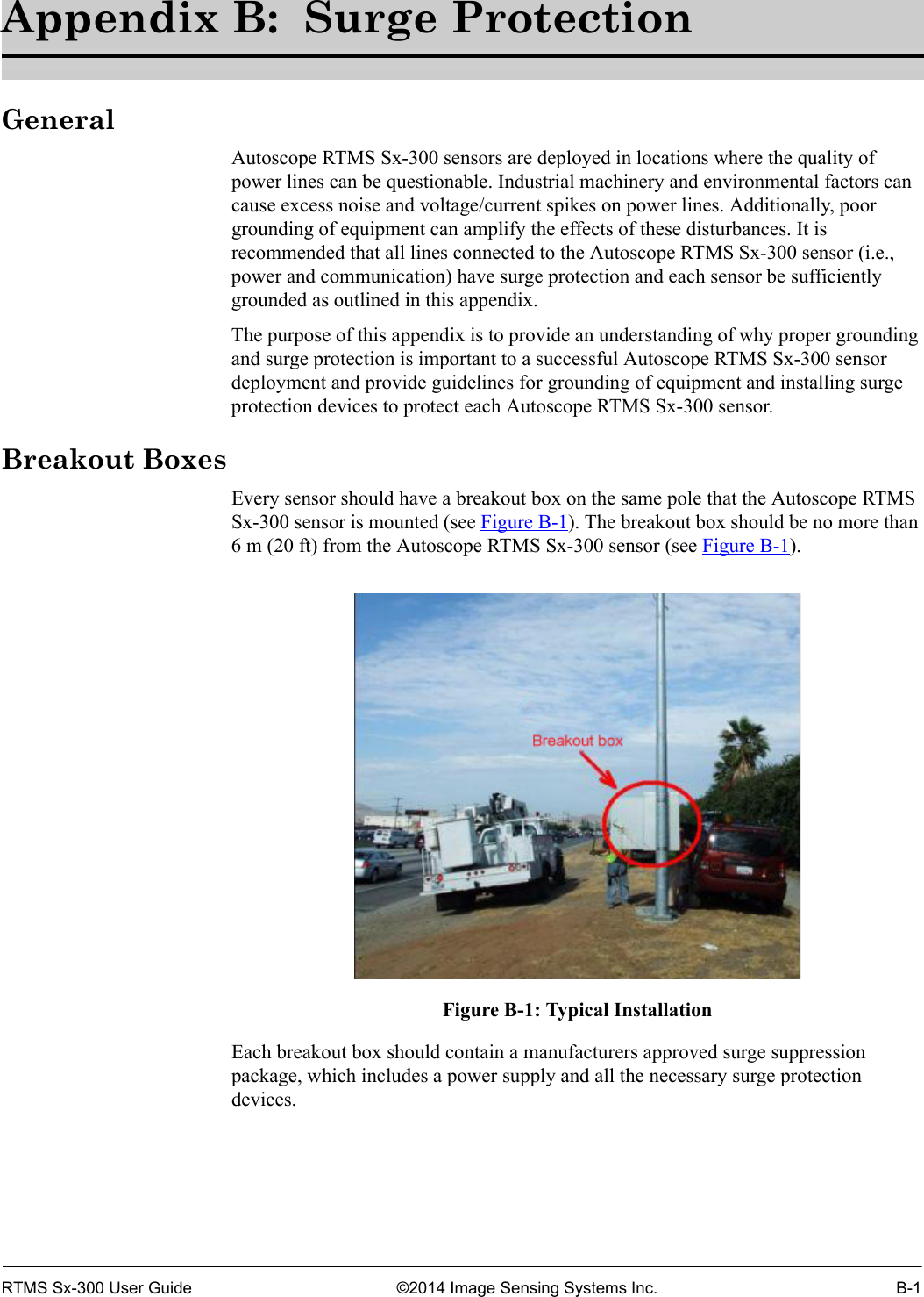
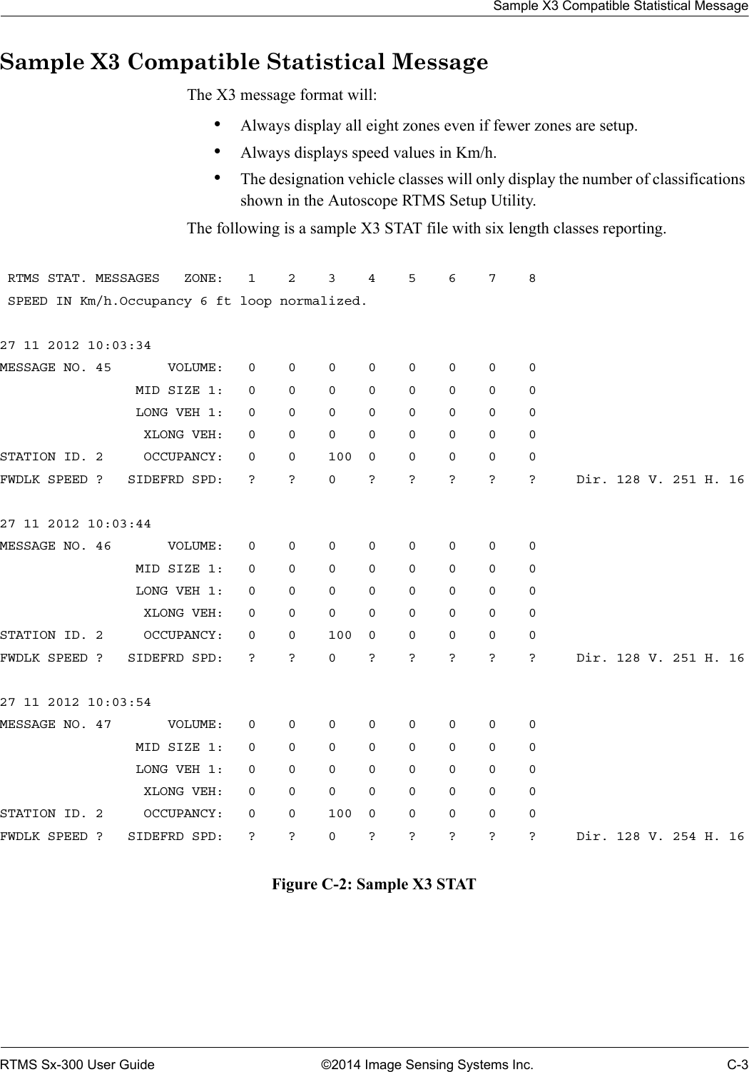
![RS-485 Port WiringRTMS Sx-300 User Guide ©2014 Image Sensing Systems Inc. A-6RS-485 Port WiringThere is no standard pin configuration for RS-485 on a DB9 connector.; so we suggest the following configuration. The wiring diagram shown will connect directly to a RS-232 configured DB9 without the need for an RS-232/RS-485 converter. The maximum cable length is 1219 m (4000 ft). Over short distances (9 m [30 ft]) the wiring diagram shown below is compatible with an RS-232 port.A disconnect point is recommended to allow the Autoscope RTMS Sx-300 to be detached from the transmission line without disruption of communications with other sensors on the line. See “Connecting Autoscope RTMS Sx-300 to External Modems” on page A-7 for details.Figure A-3: RS-485 Wiring Diagram 146923758ABCDEFGHJKLMNPRSTUVWXYZabcdefghjMS Connector Rear ViewDB-9 Female Rear ViewPower12-24VAC/DCSGNDRx–Rx+Tx–Tx+Table A-5: RS-485 Wiring MatrixDB9 Pin Signal MS Connector Pin1NC N/A2Tx- V3Rx- T4NC N/A5SGnd U6NC N/A7Rx+ Y8Tx+ X9NC N/A](https://usermanual.wiki/Image-Sensing-Systems/SX300AN/User-Guide-2271723-Page-151.png)
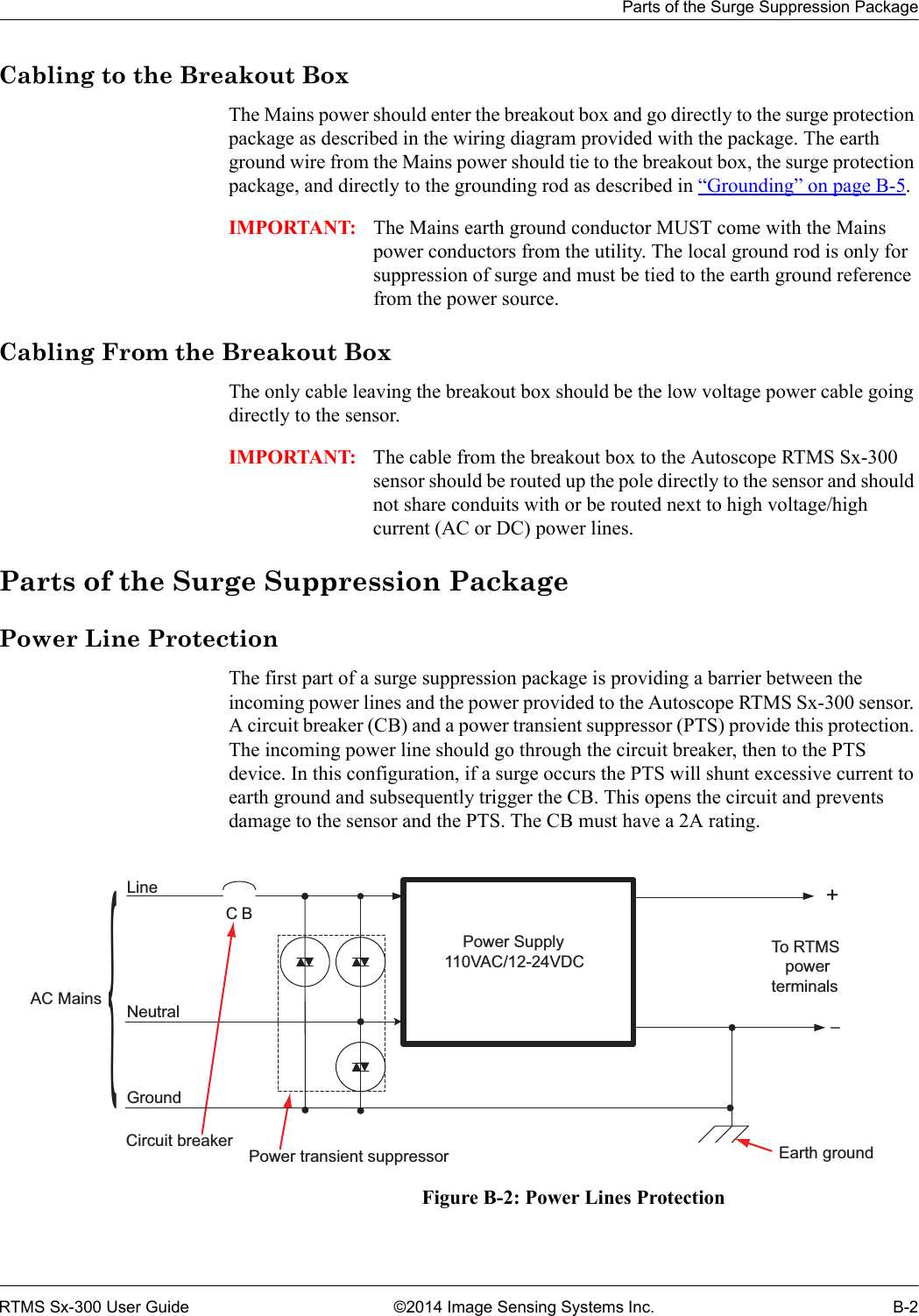


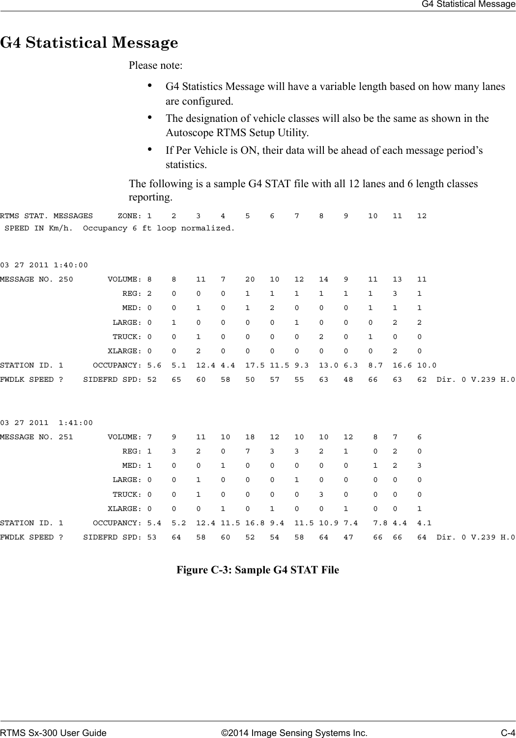
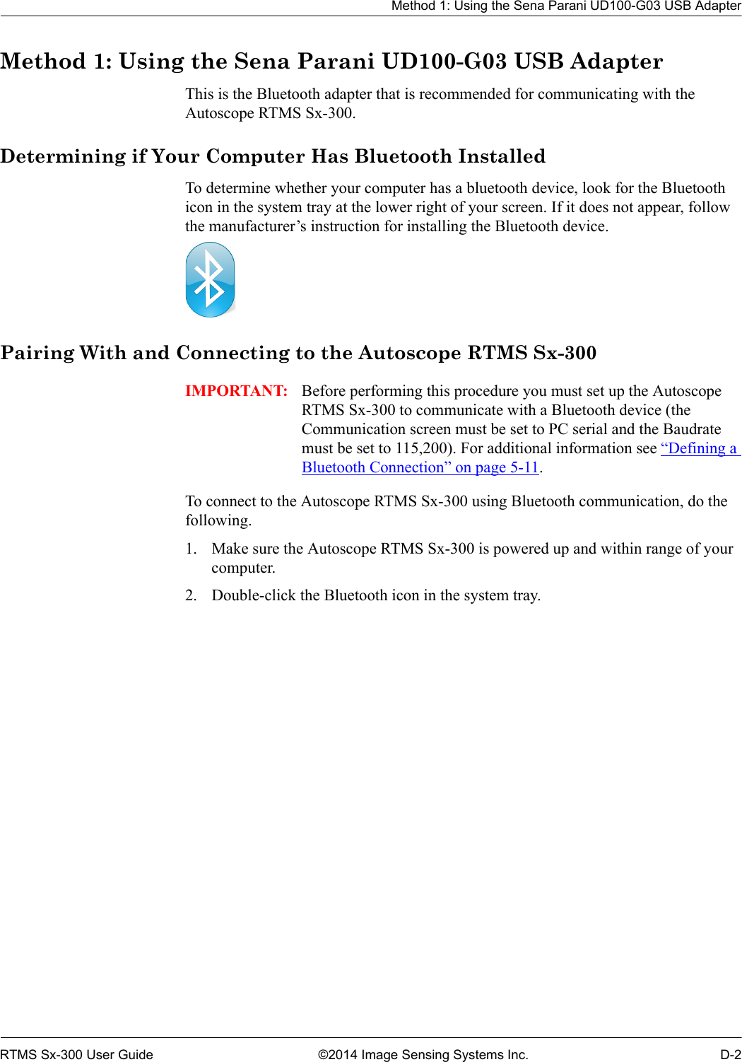
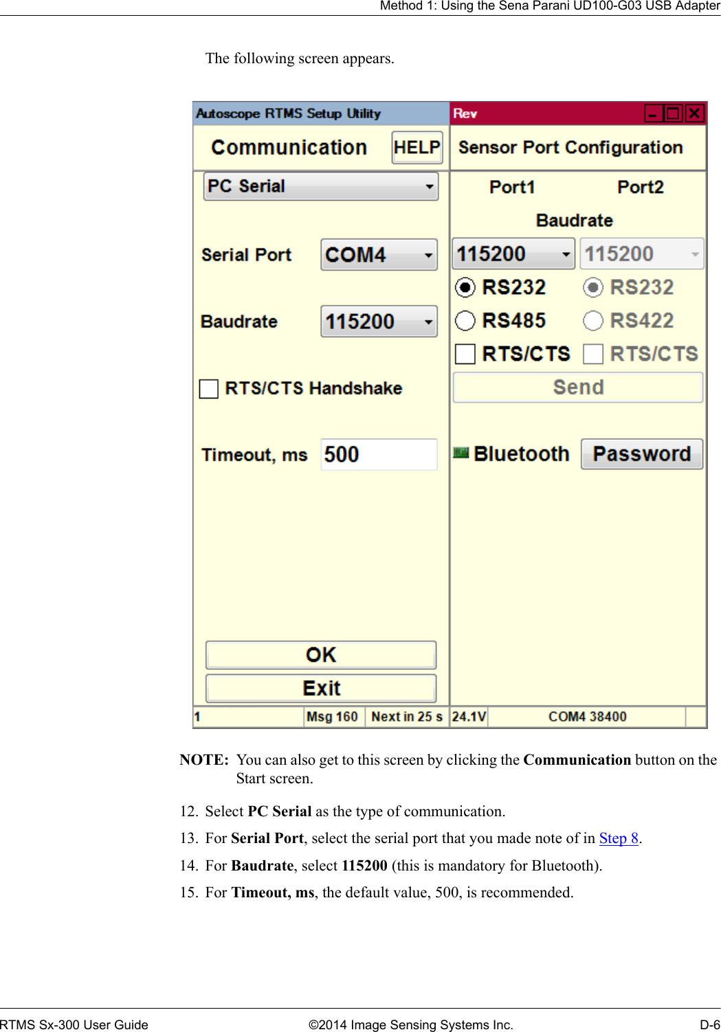
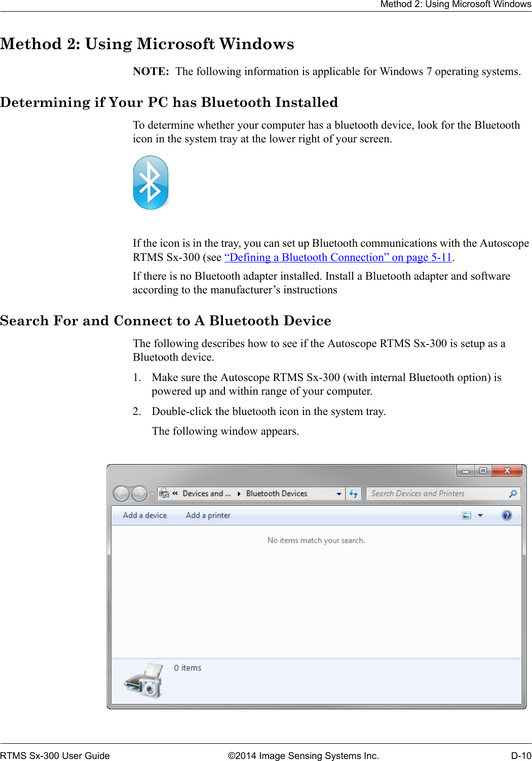
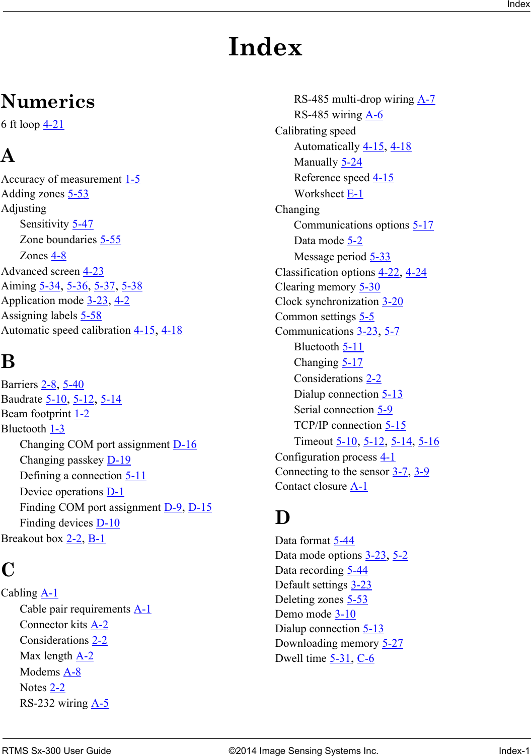
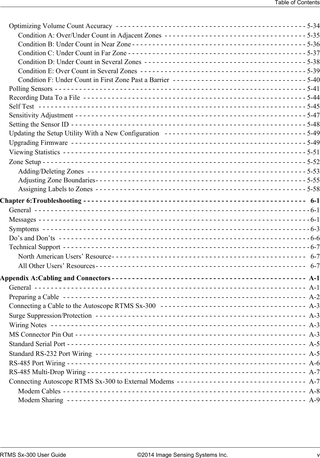
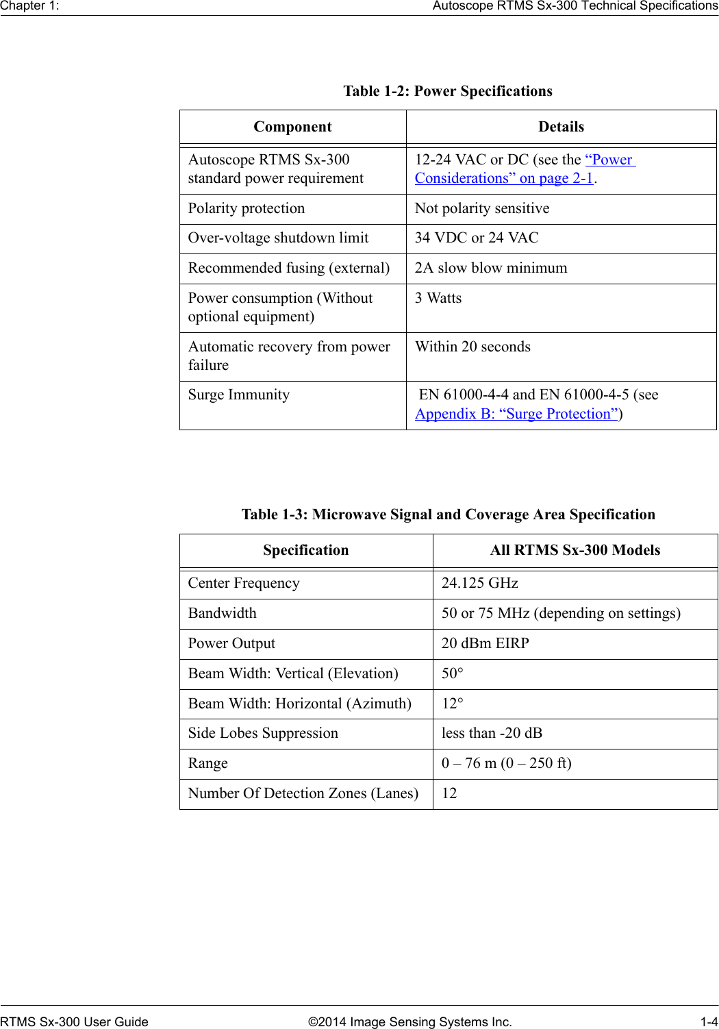
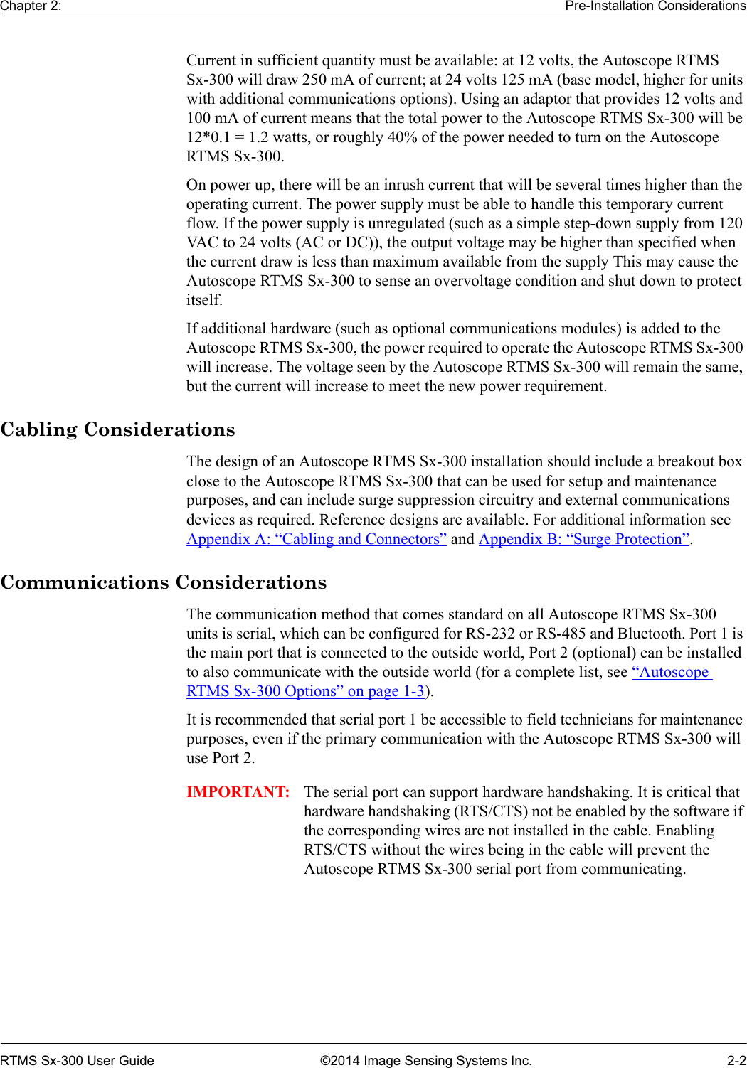
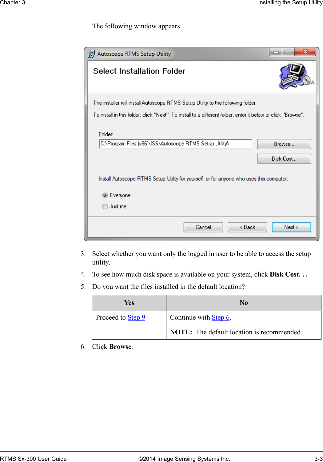
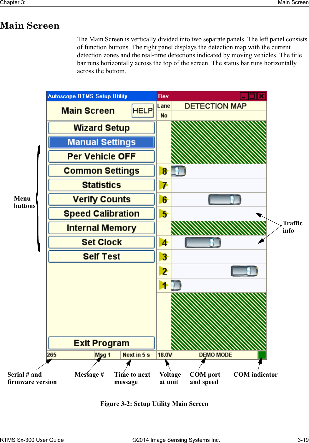
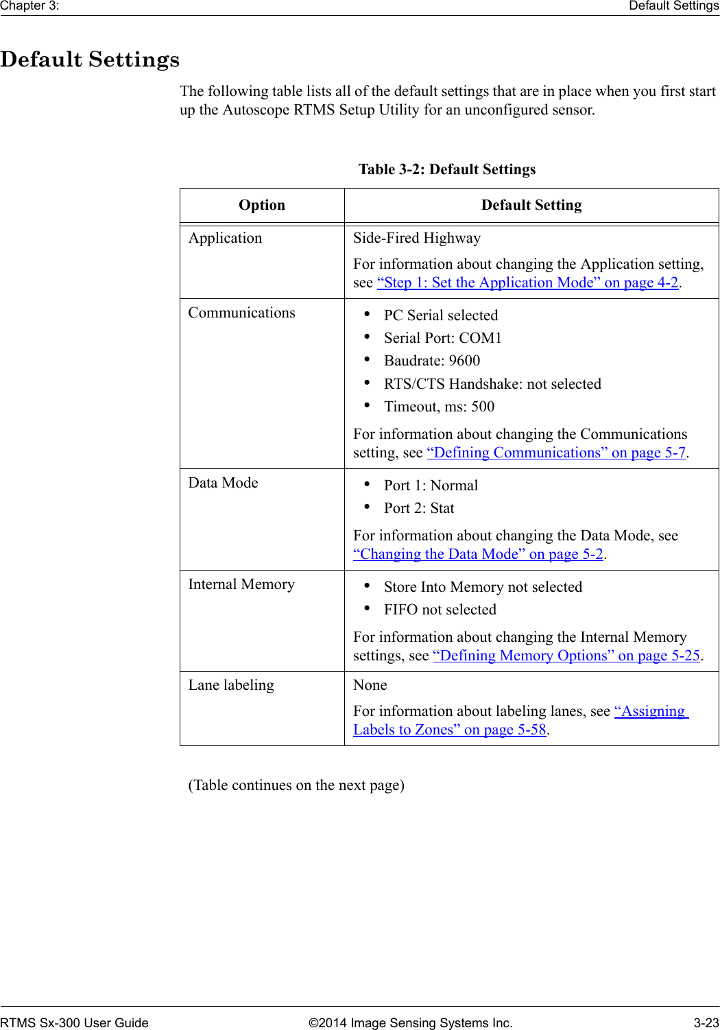
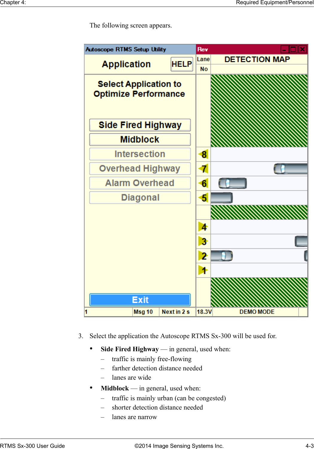
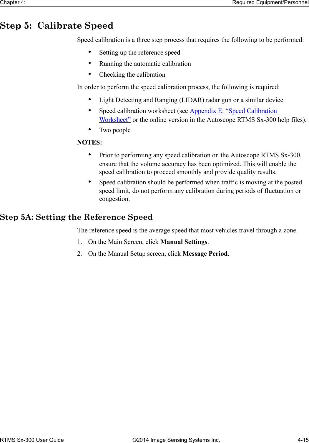
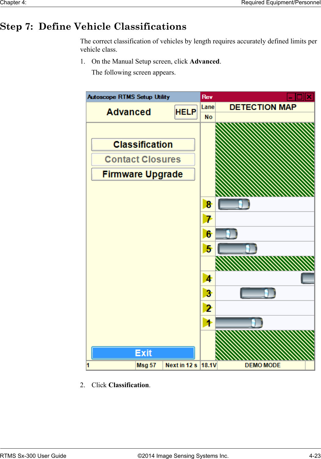
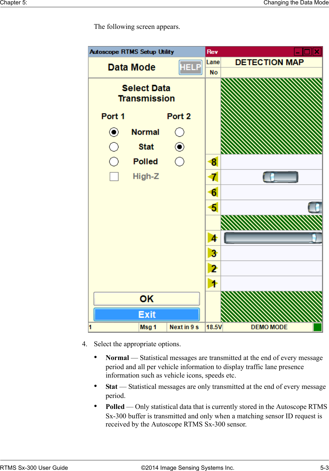
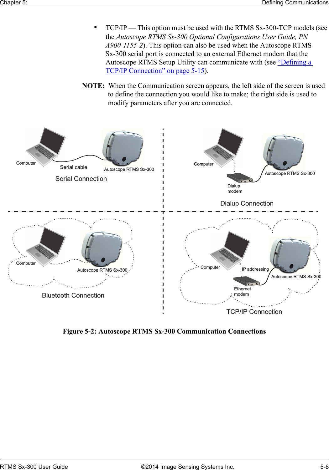
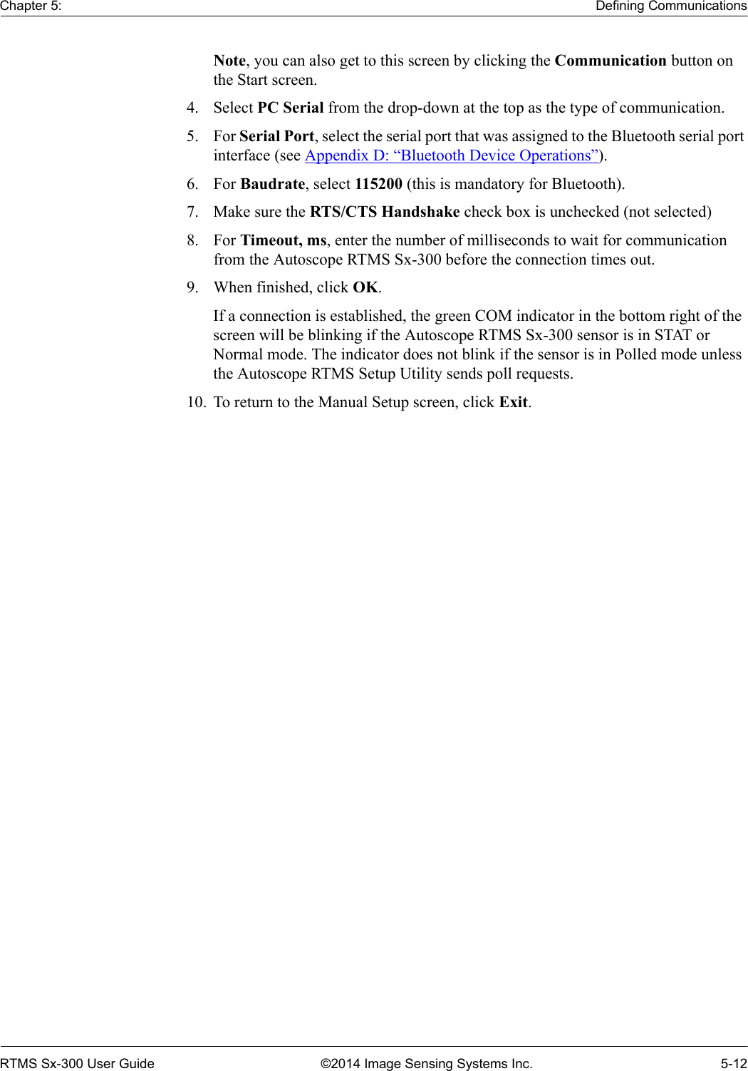
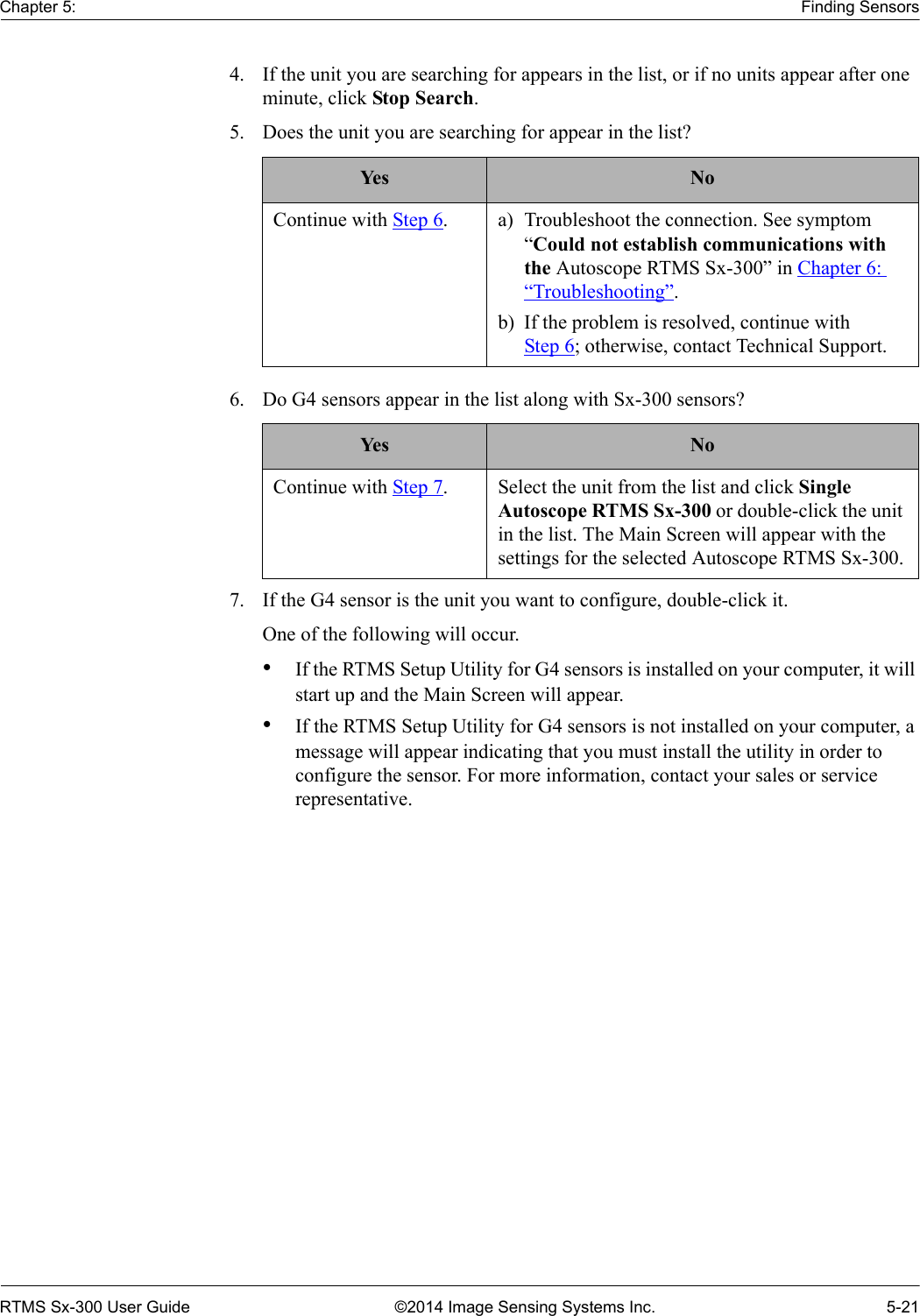
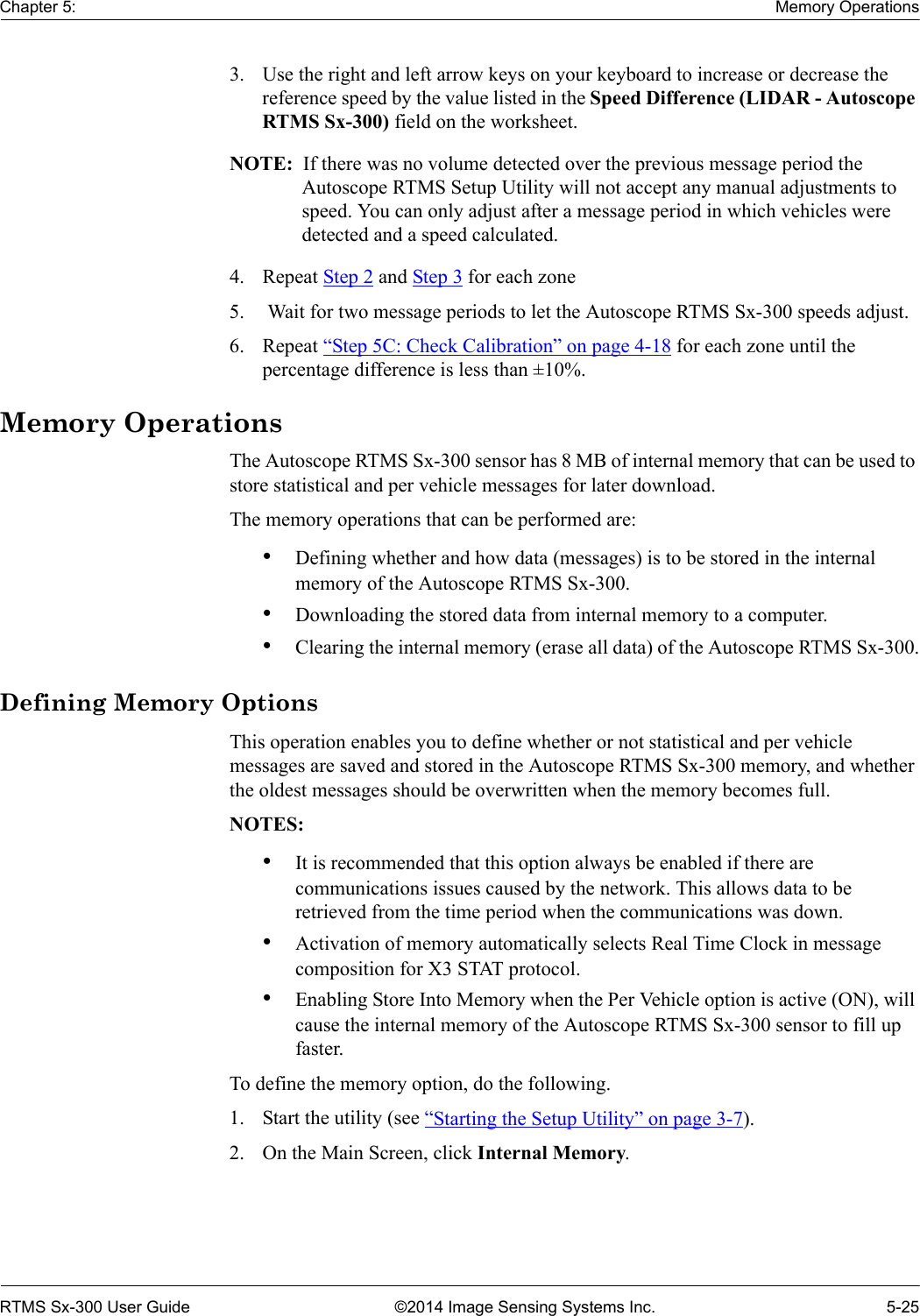
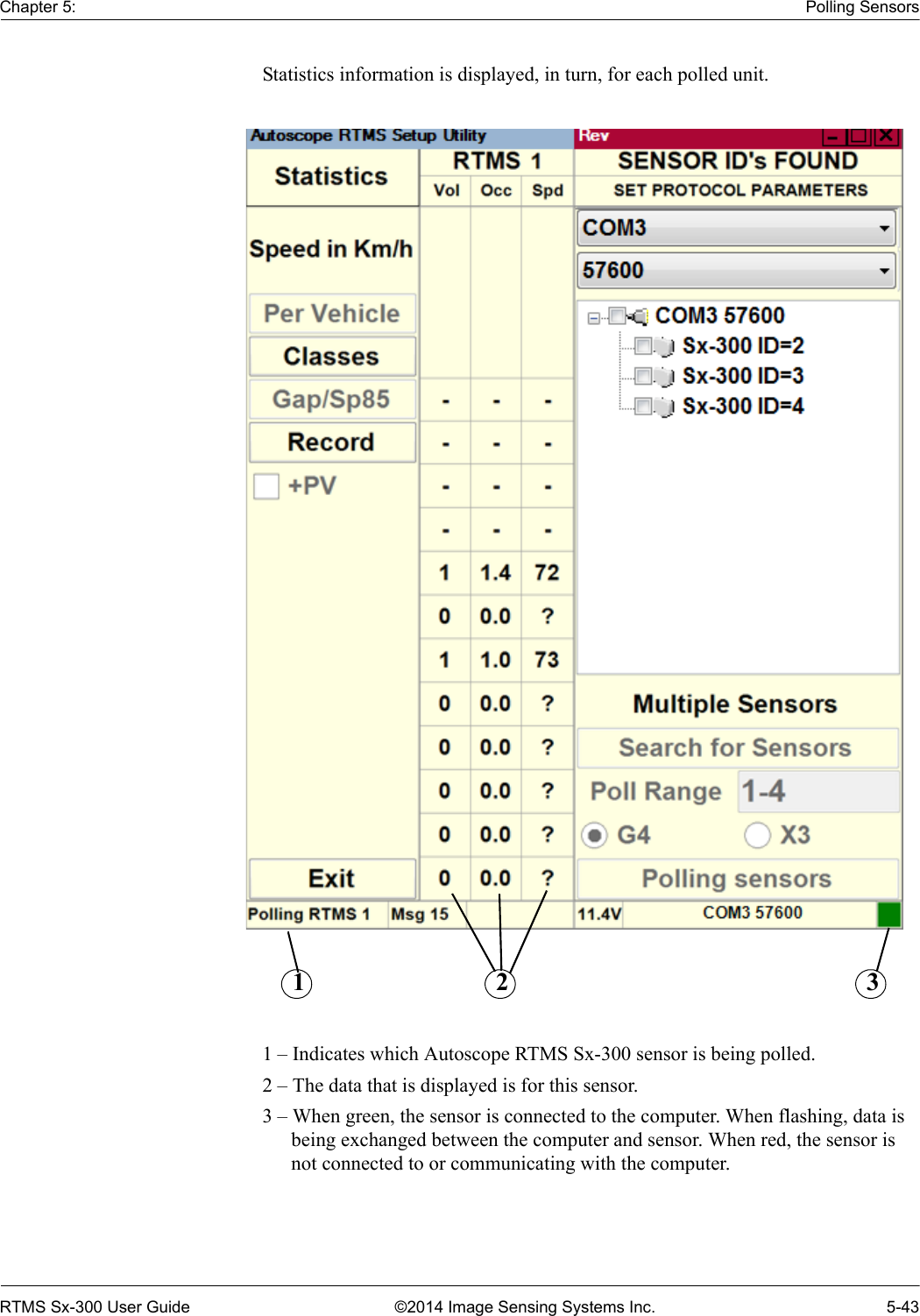
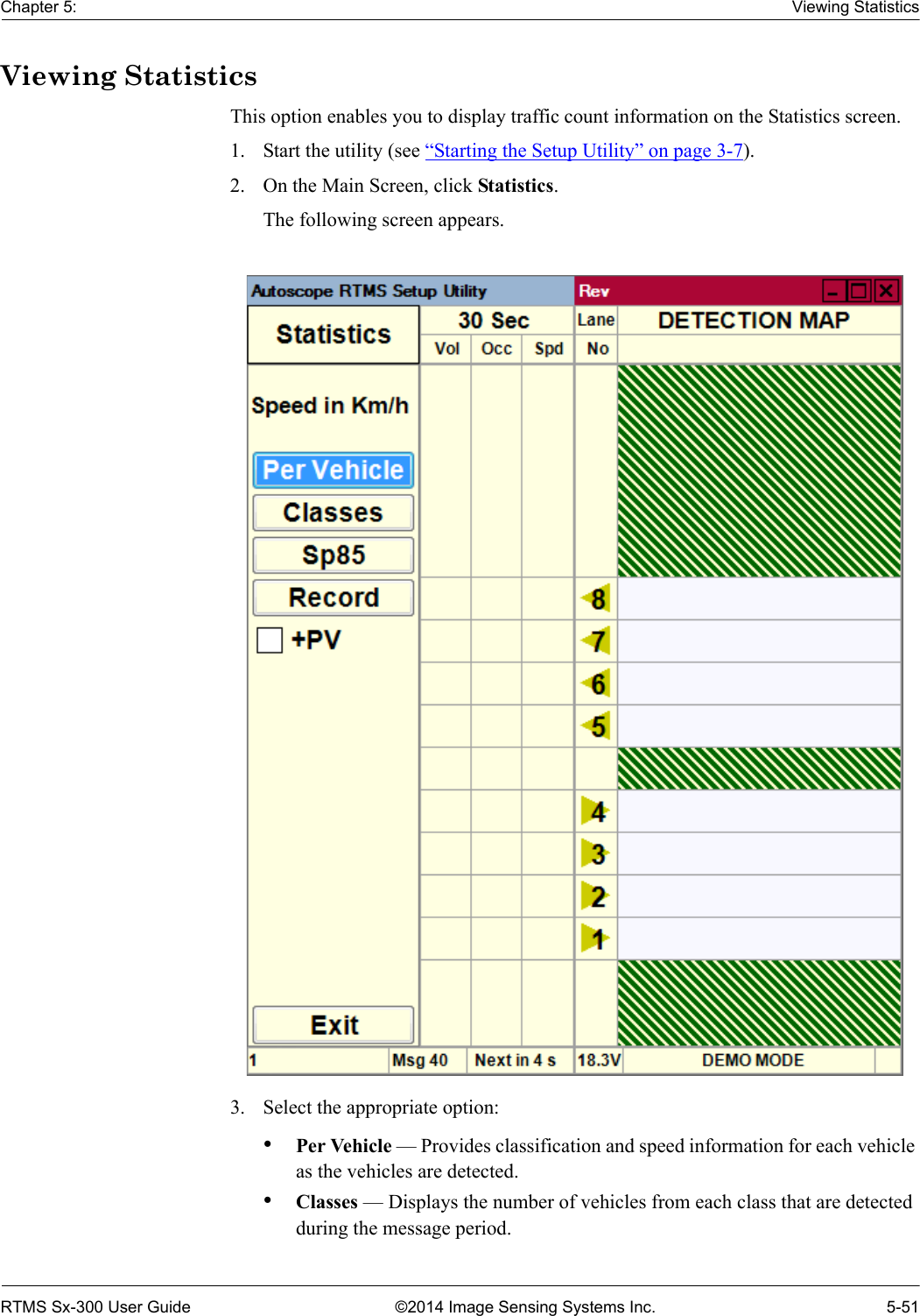
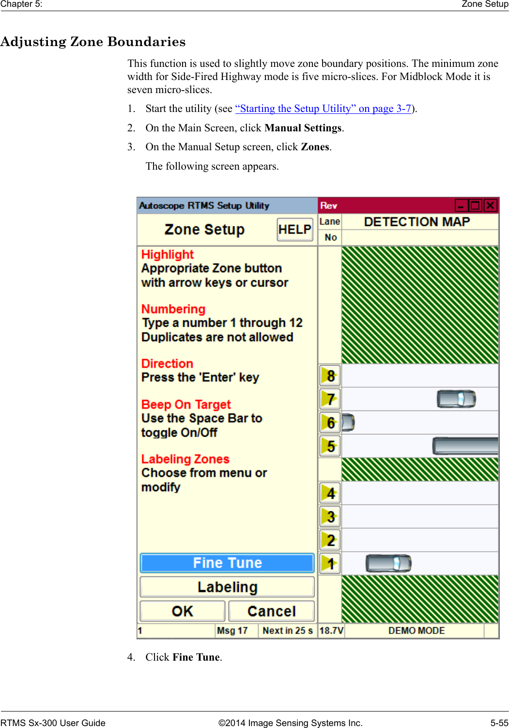
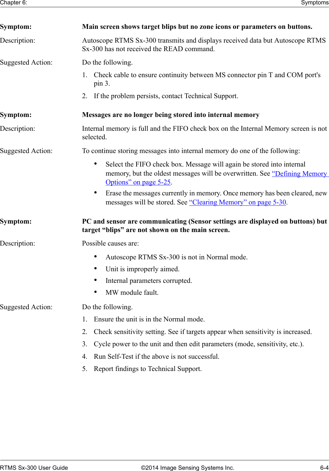
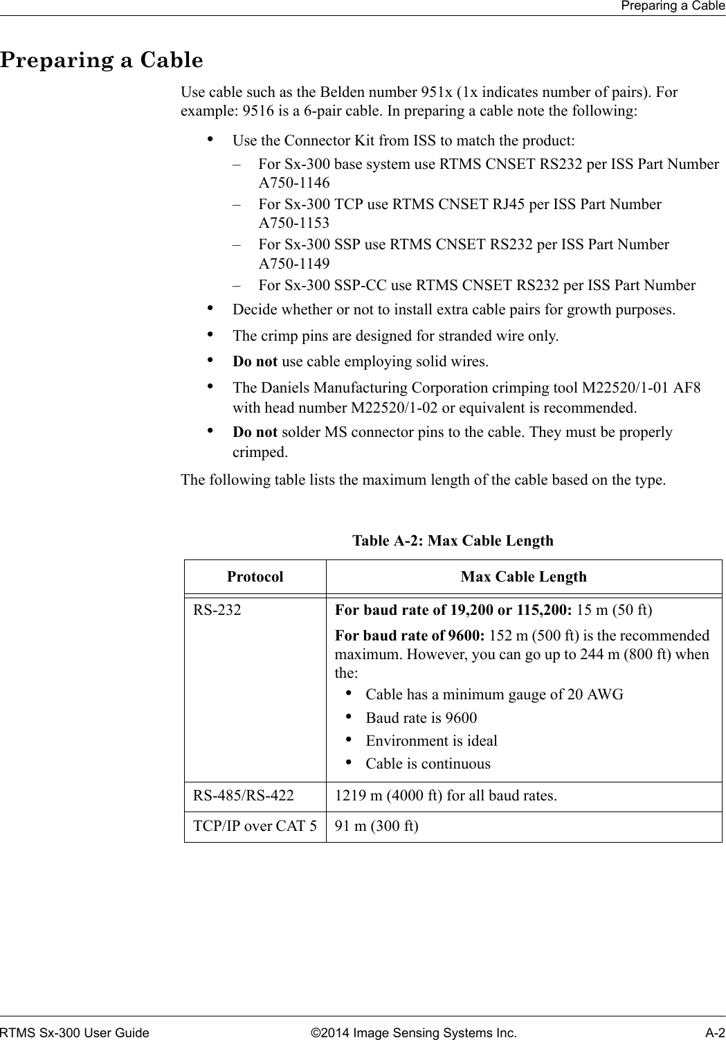
![Statistical Message with Per Vehicle OnRTMS Sx-300 User Guide ©2014 Image Sensing Systems Inc. C-5Statistical Message with Per Vehicle OnFor more information about the Per Vehicle setting, see “Defining Per Vehicle Messages” on page 5-31. RTMS STAT. MESSAGES ZONE: 1 2 3 4 5 6 7 8 9 10 11 12 SPEED IN Km/h.Occupancy 6 ft loop normalized.27 11 2012 10:11:24MESSAGE NO. 92 VOLUME: 0 0 1 0 0 0 0 0 0 0 0 0 MED: 0 0 0 0 0 0 0 0 0 0 0 0 LARGE: 0 0 0 0 0 0 0 0 0 0 0 0 TRUCK: 0 0 0 0 0 0 0 0 0 0 0 0 STATION ID. 2 OCCUPANCY: 0.0 0.0 47.2 0.0 0.0 0.0 0.0 0.0 0.0 0.0 0.0 0.0 FWDLK SPEED ? SIDEFRD SPD: ? ? 1 ? ? ? ? ? ? ? ? ? Dir. 128 V. 251 H. 16 HEADWAY: 10.0 10.0 5.0 10.0 10.0 10.0 10.0 10.0 10.0 10.0 10.0 10.0 pv RTMS_ID Lane Class Speed[km/h] Length[m] Dwellpv --------------------------------------------------pv 27 11 2012 10:11:26.470 2 3 Sm 1 3.4 602pv 27 11 2012 10:11:27.090 2 2 Sm 20 2.0 62pv 27 11 2012 10:11:28.220 2 3 Sm 3 2.0 139pv 27 11 2012 10:11:28.690 2 1 Sm 26 2.0 53pv 27 11 2012 10:11:28.710 2 3 Sm 6 2.0 70pv 27 11 2012 10:11:33.400 2 3 Sm 14 2.0 77pv 27 11 2012 10:11:33.420 2 1 Trk 26 26.8 397pv 27 11 2012 10:11:33.730 2 2 Sm 36 2.0 4127 11 2012 10:11:34MESSAGE NO. 93 VOLUME: 2 2 4 0 0 0 0 0 0 0 0 0 MED: 0 0 0 0 0 0 0 0 0 0 0 0 LARGE: 0 0 0 0 0 0 0 0 0 0 0 0 TRUCK: 1 0 0 0 0 0 0 0 0 0 0 0 STATION ID. 2 OCCUPANCY: 44.8 10.2 64.0 0.0 0.0 0.0 0.0 0.0 0.0 0.0 0.0 0.0 FWDLK SPEED ? SIDEFRD SPD: 26 28 6 ? ? ? ? ? ? ? ? ? Dir. 128 V. 251 H. 16 HEADWAY: 14.8 6.8 2.9 10.0 10.0 10.0 10.0 10.0 10.0 10.0 10.0 10.0 pv RTMS_ID Lane Class Speed[km/h] Length[m] Dwellpv --------------------------------------------------pv 27 11 2012 10:11:37.600 2 2 Trk 36 27.6 297pv 27 11 2012 10:11:42.510 2 3 Sm 7 9.0 529Figure C-4: Sample File With Per Vehicle ON](https://usermanual.wiki/Image-Sensing-Systems/SX300AN/User-Guide-2271723-Page-171.png)