Image Sensing Systems SX300AN Autoscope RTMS SX-300 User Manual Autoscope Sx 300 User Guide
Image Sensing Systems, Inc. Autoscope RTMS SX-300 Autoscope Sx 300 User Guide
User Manual
RTMS Sx-300 User Guide ©2014 Image Sensing Systems Inc. PN A900-1155-1 Rev. A
Autoscope RTMS Sx-300
User Guide
RTMS Sx-300 User Guide ©2014 Image Sensing Systems Inc. ii
Copyright
© 2014 Image Sensing Systems, Inc. All Rights Reserved. No part of this document may be reproduced or quoted
without written permission from Image Sensing Systems, Inc. Autoscope and RTMS are trademarks of Image
Sensing Systems, Inc., registered in the United States and other countries. All other product names referenced in
this guide are trademarks of their respective owners.
Record of Revisions
Revision Date Affected Pages Description
A 04/2014 Initial release.

RTMS Sx-300 User Guide ©2014 Image Sensing Systems Inc. iii
Table of Contents
Preface- - - - - - - - - - - - - - - - - - - - - - - - - - - - - - - - - - - - - - - - - - - - - - - - - - - - - - - - - - - - - - - - - - - - - - - vii
Federal Communication Commission (FCC) Notices- - - - - - - - - - - - - - - - - - - - - - - - - - - - - - - - - - - - - - vii
Industry Canada (IC) Notices- - - - - - - - - - - - - - - - - - - - - - - - - - - - - - - - - - - - - - - - - - - - - - - - - - - - - - vii
Certified Bluetooth Module - - - - - - - - - - - - - - - - - - - - - - - - - - - - - - - - - - - - - - - - - - - - - - - - - - - - - - - viii
Chapter 1:Introduction - - - - - - - - - - - - - - - - - - - - - - - - - - - - - - - - - - - - - - - - - - - - - - - - - - - - - - - - - - 1-1
General - - - - - - - - - - - - - - - - - - - - - - - - - - - - - - - - - - - - - - - - - - - - - - - - - - - - - - - - - - - - - - - - - - - - 1-1
Vehicle Detection - - - - - - - - - - - - - - - - - - - - - - - - - - - - - - - - - - - - - - - - - - - - - - - - - - - - - - - - - - - - - 1-2
Autoscope RTMS Sx-300 Options - - - - - - - - - - - - - - - - - - - - - - - - - - - - - - - - - - - - - - - - - - - - - - - - - -1-3
Autoscope RTMS Sx-300 Technical Specifications - - - - - - - - - - - - - - - - - - - - - - - - - - - - - - - - - - - - - - 1-3
Environmental Conditions - - - - - - - - - - - - - - - - - - - - - - - - - - - - - - - - - - - - - - - - - - - - - - - - - - - - - - - 1-6
Electromagnetic Interference - - - - - - - - - - - - - - - - - - - - - - - - - - - - - - - - - - - - - - - - - - - - - - - - - - - - - 1-6
Upgrade Capability - - - - - - - - - - - - - - - - - - - - - - - - - - - - - - - - - - - - - - - - - - - - - - - - - - - - - - - - - - - - 1-6
Chapter 2:Hardware Installation - - - - - - - - - - - - - - - - - - - - - - - - - - - - - - - - - - - - - - - - - - - - - - - - - - - 2-1
General - - - - - - - - - - - - - - - - - - - - - - - - - - - - - - - - - - - - - - - - - - - - - - - - - - - - - - - - - - - - - - - - - - - - 2-1
Safety Information - - - - - - - - - - - - - - - - - - - - - - - - - - - - - - - - - - - - - - - - - - - - - - - - - - - - - - - - - - - - 2-1
Pre-Installation Considerations - - - - - - - - - - - - - - - - - - - - - - - - - - - - - - - - - - - - - - - - - - - - - - - - - - - - 2-1
Power Considerations - - - - - - - - - - - - - - - - - - - - - - - - - - - - - - - - - - - - - - - - - - - - - - - - - - - - - - - 2-1
Cabling Considerations - - - - - - - - - - - - - - - - - - - - - - - - - - - - - - - - - - - - - - - - - - - - - - - - - - - - - - 2-2
Communications Considerations - - - - - - - - - - - - - - - - - - - - - - - - - - - - - - - - - - - - - - - - - - - - - - - - 2-2
Placement in Side-Fired Highway Configuration - - - - - - - - - - - - - - - - - - - - - - - - - - - - - - - - - - - - - - - - 2-3
Height and Setback Requirements - - - - - - - - - - - - - - - - - - - - - - - - - - - - - - - - - - - - - - - - - - - - - - - - 2-5
Zero Setback - - - - - - - - - - - - - - - - - - - - - - - - - - - - - - - - - - - - - - - - - - - - - - - - - - - - - - - - - - - 2-5
Standard Setback - - - - - - - - - - - - - - - - - - - - - - - - - - - - - - - - - - - - - - - - - - - - - - - - - - - - - - - - 2-5
Guardrails and Barriers - - - - - - - - - - - - - - - - - - - - - - - - - - - - - - - - - - - - - - - - - - - - - - - - - - - - - - 2-8
Elevated Roadway- - - - - - - - - - - - - - - - - - - - - - - - - - - - - - - - - - - - - - - - - - - - - - - - - - - - - - - - - - - 2-9
Sunken Road and Roadside Walls - - - - - - - - - - - - - - - - - - - - - - - - - - - - - - - - - - - - - - - - - - - - - - - 2-10
Installing Autoscope RTMS Sx-300 on Sign Structures - - - - - - - - - - - - - - - - - - - - - - - - - - - - - - - - 2-10
Grade Differentials - - - - - - - - - - - - - - - - - - - - - - - - - - - - - - - - - - - - - - - - - - - - - - - - - - - - - - - - 2-11
Trees - - - - - - - - - - - - - - - - - - - - - - - - - - - - - - - - - - - - - - - - - - - - - - - - - - - - - - - - - - - - - - - - - - 2-11
Placement in Midblock Applications - - - - - - - - - - - - - - - - - - - - - - - - - - - - - - - - - - - - - - - - - - - - - - -2-12
Mounting and Aiming Procedure - - - - - - - - - - - - - - - - - - - - - - - - - - - - - - - - - - - - - - - - - - - - - - - - - -2-12
Chapter 3:RTMS Setup Utility - - - - - - - - - - - - - - - - - - - - - - - - - - - - - - - - - - - - - - - - - - - - - - - - - - - - 3-1
General - - - - - - - - - - - - - - - - - - - - - - - - - - - - - - - - - - - - - - - - - - - - - - - - - - - - - - - - - - - - - - - - - - - - 3-1
System Requirements - - - - - - - - - - - - - - - - - - - - - - - - - - - - - - - - - - - - - - - - - - - - - - - - - - - - - - - - - - 3-1
Installing the Setup Utility - - - - - - - - - - - - - - - - - - - - - - - - - - - - - - - - - - - - - - - - - - - - - - - - - - - - - - - 3-2
Starting the Setup Utility - - - - - - - - - - - - - - - - - - - - - - - - - - - - - - - - - - - - - - - - - - - - - - - - - - - - - - - - 3-7
For Networks With Only RTMS Sx-300 Sensors - - - - - - - - - - - - - - - - - - - - - - - - - - - - - - - - - - - - - 3-7
For Multidrop Networks With RTMS Sx-300 and RTMS G4 Sensors - - - - - - - - - - - - - - - - - - - - - - - - 3-9
Navigating the Setup Utility - - - - - - - - - - - - - - - - - - - - - - - - - - - - - - - - - - - - - - - - - - - - - - - - - - - - - 3-10
Running Demo Mode - - - - - - - - - - - - - - - - - - - - - - - - - - - - - - - - - - - - - - - - - - - - - - - - - - - - - - - - - 3-10

Table of Contents
RTMS Sx-300 User Guide ©2014 Image Sensing Systems Inc. iv
Setup Utility Screens - - - - - - - - - - - - - - - - - - - - - - - - - - - - - - - - - - - - - - - - - - - - - - - - - - - - - - - - - - 3-15
Start Screen - - - - - - - - - - - - - - - - - - - - - - - - - - - - - - - - - - - - - - - - - - - - - - - - - - - - - - - - - - - - - - - - 3-17
Main Screen - - - - - - - - - - - - - - - - - - - - - - - - - - - - - - - - - - - - - - - - - - - - - - - - - - - - - - - - - - - - - - - - 3-19
Manual Setup Screen - - - - - - - - - - - - - - - - - - - - - - - - - - - - - - - - - - - - - - - - - - - - - - - - - - - - - - - - - - 3-21
Default Settings - - - - - - - - - - - - - - - - - - - - - - - - - - - - - - - - - - - - - - - - - - - - - - - - - - - - - - - - - - - - - 3-23
Chapter 4:Configuration and Setup - - - - - - - - - - - - - - - - - - - - - - - - - - - - - - - - - - - - - - - - - - - - - - - - - 4-1
General - - - - - - - - - - - - - - - - - - - - - - - - - - - - - - - - - - - - - - - - - - - - - - - - - - - - - - - - - - - - - - - - - - - - 4-1
Configuration Process - - - - - - - - - - - - - - - - - - - - - - - - - - - - - - - - - - - - - - - - - - - - - - - - - - - - - - - - - - 4-1
Required Equipment/Personnel - - - - - - - - - - - - - - - - - - - - - - - - - - - - - - - - - - - - - - - - - - - - - - - - - - - - 4-1
Step 1: Set the Application Mode - - - - - - - - - - - - - - - - - - - - - - - - - - - - - - - - - - - - - - - - - - - - - - - - - - 4-2
Step 2: Run the Wizard - - - - - - - - - - - - - - - - - - - - - - - - - - - - - - - - - - - - - - - - - - - - - - - - - - - - - - - - - 4-5
Step 3: Adjust the Zones - - - - - - - - - - - - - - - - - - - - - - - - - - - - - - - - - - - - - - - - - - - - - - - - - - - - - - - - 4-8
Step 4: Verify Vehicle Counts - - - - - - - - - - - - - - - - - - - - - - - - - - - - - - - - - - - - - - - - - - - - - - - - - - - - 4-10
Step 5: Calibrate Speed - - - - - - - - - - - - - - - - - - - - - - - - - - - - - - - - - - - - - - - - - - - - - - - - - - - - - - - - 4-15
Step 5A: Setting the Reference Speed- - - - - - - - - - - - - - - - - - - - - - - - - - - - - - - - - - - - - - - - - - - - 4-15
Step 5B: Auto Calibration- - - - - - - - - - - - - - - - - - - - - - - - - - - - - - - - - - - - - - - - - - - - - - - - - - - - 4-18
Step 5C: Check Calibration- - - - - - - - - - - - - - - - - - - - - - - - - - - - - - - - - - - - - - - - - - - - - - - - - - - 4-18
Step 6: Define Message Composition - - - - - - - - - - - - - - - - - - - - - - - - - - - - - - - - - - - - - - - - - - - - - - -4-20
Step 7: Define Vehicle Classifications - - - - - - - - - - - - - - - - - - - - - - - - - - - - - - - - - - - - - - - - - - - - - - 4-23
Step 8: Save the Configuration File - - - - - - - - - - - - - - - - - - - - - - - - - - - - - - - - - - - - - - - - - - - - - - - - 4-27
Chapter 5:Operations and Adjustments - - - - - - - - - - - - - - - - - - - - - - - - - - - - - - - - - - - - - - - - - - - - - - 5-1
General - - - - - - - - - - - - - - - - - - - - - - - - - - - - - - - - - - - - - - - - - - - - - - - - - - - - - - - - - - - - - - - - - - - - 5-1
Advanced Options - - - - - - - - - - - - - - - - - - - - - - - - - - - - - - - - - - - - - - - - - - - - - - - - - - - - - - - - - - - - - 5-1
Changing the Data Mode - - - - - - - - - - - - - - - - - - - - - - - - - - - - - - - - - - - - - - - - - - - - - - - - - - - - - - - - 5-2
Common Setup Options - - - - - - - - - - - - - - - - - - - - - - - - - - - - - - - - - - - - - - - - - - - - - - - - - - - - - - - - - 5-5
Defining Communications - - - - - - - - - - - - - - - - - - - - - - - - - - - - - - - - - - - - - - - - - - - - - - - - - - - - - - - 5-7
Defining a Serial Connection- - - - - - - - - - - - - - - - - - - - - - - - - - - - - - - - - - - - - - - - - - - - - - - - - - - - 5-9
Defining a Bluetooth Connection - - - - - - - - - - - - - - - - - - - - - - - - - - - - - - - - - - - - - - - - - - - - - - - - 5-11
Defining a Dialup Connection - - - - - - - - - - - - - - - - - - - - - - - - - - - - - - - - - - - - - - - - - - - - - - - - - - 5-13
Defining a TCP/IP Connection - - - - - - - - - - - - - - - - - - - - - - - - - - - - - - - - - - - - - - - - - - - - - - - - - 5-15
Changing an Existing Connection - - - - - - - - - - - - - - - - - - - - - - - - - - - - - - - - - - - - - - - - - - - - - - - 5-17
Finding Sensors - - - - - - - - - - - - - - - - - - - - - - - - - - - - - - - - - - - - - - - - - - - - - - - - - - - - - - - - - - - - - 5-19
Loading a Previously Saved Setup File - - - - - - - - - - - - - - - - - - - - - - - - - - - - - - - - - - - - - - - - - - - - - -5-22
Manual Speed Calibration - - - - - - - - - - - - - - - - - - - - - - - - - - - - - - - - - - - - - - - - - - - - - - - - - - - - - - 5-24
Memory Operations - - - - - - - - - - - - - - - - - - - - - - - - - - - - - - - - - - - - - - - - - - - - - - - - - - - - - - - - - - - 5-25
Defining Memory Options - - - - - - - - - - - - - - - - - - - - - - - - - - - - - - - - - - - - - - - - - - - - - - - - - - - 5-25
Downloading Autoscope RTMS Sx-300 Memory- - - - - - - - - - - - - - - - - - - - - - - - - - - - - - - - - - - - - 5-27
Clearing Memory - - - - - - - - - - - - - - - - - - - - - - - - - - - - - - - - - - - - - - - - - - - - - - - - - - - - - - - - - - 5-30
Message Operations - - - - - - - - - - - - - - - - - - - - - - - - - - - - - - - - - - - - - - - - - - - - - - - - - - - - - - - - - - 5-31
Defining the Message Composition - - - - - - - - - - - - - - - - - - - - - - - - - - - - - - - - - - - - - - - - - - - - - 5-31
Defining Per Vehicle Messages - - - - - - - - - - - - - - - - - - - - - - - - - - - - - - - - - - - - - - - - - - - - - - - - 5-31
Changing the Message Period - - - - - - - - - - - - - - - - - - - - - - - - - - - - - - - - - - - - - - - - - - - - - - - - - - 5-33

Table of Contents
RTMS Sx-300 User Guide ©2014 Image Sensing Systems Inc. v
Optimizing Volume Count Accuracy - - - - - - - - - - - - - - - - - - - - - - - - - - - - - - - - - - - - - - - - - - - - - - - 5-34
Condition A: Over/Under Count in Adjacent Zones - - - - - - - - - - - - - - - - - - - - - - - - - - - - - - - - - - - 5-35
Condition B: Under Count in Near Zone - - - - - - - - - - - - - - - - - - - - - - - - - - - - - - - - - - - - - - - - - - - 5-36
Condition C: Under Count in Far Zone - - - - - - - - - - - - - - - - - - - - - - - - - - - - - - - - - - - - - - - - - - - - 5-37
Condition D: Under Count in Several Zones - - - - - - - - - - - - - - - - - - - - - - - - - - - - - - - - - - - - - - - - 5-38
Condition E: Over Count in Several Zones - - - - - - - - - - - - - - - - - - - - - - - - - - - - - - - - - - - - - - - - - 5-39
Condition F: Under Count in First Zone Past a Barrier - - - - - - - - - - - - - - - - - - - - - - - - - - - - - - - - - 5-40
Polling Sensors - - - - - - - - - - - - - - - - - - - - - - - - - - - - - - - - - - - - - - - - - - - - - - - - - - - - - - - - - - - - - - 5-41
Recording Data To a File - - - - - - - - - - - - - - - - - - - - - - - - - - - - - - - - - - - - - - - - - - - - - - - - - - - - - - - 5-44
Self Test - - - - - - - - - - - - - - - - - - - - - - - - - - - - - - - - - - - - - - - - - - - - - - - - - - - - - - - - - - - - - - - - - - 5-45
Sensitivity Adjustment - - - - - - - - - - - - - - - - - - - - - - - - - - - - - - - - - - - - - - - - - - - - - - - - - - - - - - - - - 5-47
Setting the Sensor ID - - - - - - - - - - - - - - - - - - - - - - - - - - - - - - - - - - - - - - - - - - - - - - - - - - - - - - - - - - 5-48
Updating the Setup Utility With a New Configuration - - - - - - - - - - - - - - - - - - - - - - - - - - - - - - - - - - - 5-49
Upgrading Firmware - - - - - - - - - - - - - - - - - - - - - - - - - - - - - - - - - - - - - - - - - - - - - - - - - - - - - - - - - - 5-49
Viewing Statistics - - - - - - - - - - - - - - - - - - - - - - - - - - - - - - - - - - - - - - - - - - - - - - - - - - - - - - - - - - - - 5-51
Zone Setup - - - - - - - - - - - - - - - - - - - - - - - - - - - - - - - - - - - - - - - - - - - - - - - - - - - - - - - - - - - - - - - - - 5-52
Adding/Deleting Zones - - - - - - - - - - - - - - - - - - - - - - - - - - - - - - - - - - - - - - - - - - - - - - - - - - - - - -5-53
Adjusting Zone Boundaries- - - - - - - - - - - - - - - - - - - - - - - - - - - - - - - - - - - - - - - - - - - - - - - - - - - -5-55
Assigning Labels to Zones - - - - - - - - - - - - - - - - - - - - - - - - - - - - - - - - - - - - - - - - - - - - - - - - - - - -5-58
Chapter 6:Troubleshooting - - - - - - - - - - - - - - - - - - - - - - - - - - - - - - - - - - - - - - - - - - - - - - - - - - - - - - - 6-1
General - - - - - - - - - - - - - - - - - - - - - - - - - - - - - - - - - - - - - - - - - - - - - - - - - - - - - - - - - - - - - - - - - - - - 6-1
Messages - - - - - - - - - - - - - - - - - - - - - - - - - - - - - - - - - - - - - - - - - - - - - - - - - - - - - - - - - - - - - - - - - - - 6-1
Symptoms - - - - - - - - - - - - - - - - - - - - - - - - - - - - - - - - - - - - - - - - - - - - - - - - - - - - - - - - - - - - - - - - - - 6-3
Do’s and Don’ts - - - - - - - - - - - - - - - - - - - - - - - - - - - - - - - - - - - - - - - - - - - - - - - - - - - - - - - - - - - - - - 6-6
Technical Support - - - - - - - - - - - - - - - - - - - - - - - - - - - - - - - - - - - - - - - - - - - - - - - - - - - - - - - - - - - - - 6-7
North American Users’ Resource- - - - - - - - - - - - - - - - - - - - - - - - - - - - - - - - - - - - - - - - - - - - - - - - 6-7
All Other Users’ Resources- - - - - - - - - - - - - - - - - - - - - - - - - - - - - - - - - - - - - - - - - - - - - - - - - - - - 6-7
Appendix A:Cabling and Connectors - - - - - - - - - - - - - - - - - - - - - - - - - - - - - - - - - - - - - - - - - - - - - - - - A-1
General - - - - - - - - - - - - - - - - - - - - - - - - - - - - - - - - - - - - - - - - - - - - - - - - - - - - - - - - - - - - - - - - - - - A-1
Preparing a Cable - - - - - - - - - - - - - - - - - - - - - - - - - - - - - - - - - - - - - - - - - - - - - - - - - - - - - - - - - - - - A-2
Connecting a Cable to the Autoscope RTMS Sx-300 - - - - - - - - - - - - - - - - - - - - - - - - - - - - - - - - - - - - A-3
Surge Suppression/Protection - - - - - - - - - - - - - - - - - - - - - - - - - - - - - - - - - - - - - - - - - - - - - - - - - - - - A-3
Wiring Notes - - - - - - - - - - - - - - - - - - - - - - - - - - - - - - - - - - - - - - - - - - - - - - - - - - - - - - - - - - - - - - - A-3
MS Connector Pin Out - - - - - - - - - - - - - - - - - - - - - - - - - - - - - - - - - - - - - - - - - - - - - - - - - - - - - - - - - A-3
Standard Serial Port - - - - - - - - - - - - - - - - - - - - - - - - - - - - - - - - - - - - - - - - - - - - - - - - - - - - - - - - - - - A-5
Standard RS-232 Port Wiring - - - - - - - - - - - - - - - - - - - - - - - - - - - - - - - - - - - - - - - - - - - - - - - - - - - - A-5
RS-485 Port Wiring - - - - - - - - - - - - - - - - - - - - - - - - - - - - - - - - - - - - - - - - - - - - - - - - - - - - - - - - - - - A-6
RS-485 Multi-Drop Wiring - - - - - - - - - - - - - - - - - - - - - - - - - - - - - - - - - - - - - - - - - - - - - - - - - - - - - - A-7
Connecting Autoscope RTMS Sx-300 to External Modems - - - - - - - - - - - - - - - - - - - - - - - - - - - - - - - - A-7
Modem Cables - - - - - - - - - - - - - - - - - - - - - - - - - - - - - - - - - - - - - - - - - - - - - - - - - - - - - - - - - - - - A-8
Modem Sharing - - - - - - - - - - - - - - - - - - - - - - - - - - - - - - - - - - - - - - - - - - - - - - - - - - - - - - - - - - - A-9

Table of Contents
RTMS Sx-300 User Guide ©2014 Image Sensing Systems Inc. vi
Appendix B:Surge Protection - - - - - - - - - - - - - - - - - - - - - - - - - - - - - - - - - - - - - - - - - - - - - - - - - - - - - B-1
General - - - - - - - - - - - - - - - - - - - - - - - - - - - - - - - - - - - - - - - - - - - - - - - - - - - - - - - - - - - - - - - - - - - B-1
Breakout Boxes - - - - - - - - - - - - - - - - - - - - - - - - - - - - - - - - - - - - - - - - - - - - - - - - - - - - - - - - - - - - - B-1
Cabling to the Breakout Box - - - - - - - - - - - - - - - - - - - - - - - - - - - - - - - - - - - - - - - - - - - - - - - - - - - B-2
Cabling From the Breakout Box - - - - - - - - - - - - - - - - - - - - - - - - - - - - - - - - - - - - - - - - - - - - - - - - B-2
Parts of the Surge Suppression Package - - - - - - - - - - - - - - - - - - - - - - - - - - - - - - - - - - - - - - - - - - - - - B-2
Power Line Protection - - - - - - - - - - - - - - - - - - - - - - - - - - - - - - - - - - - - - - - - - - - - - - - - - - - - - - - B-2
Communication Line Protection - - - - - - - - - - - - - - - - - - - - - - - - - - - - - - - - - - - - - - - - - - - - - - - - B-3
Grounding - - - - - - - - - - - - - - - - - - - - - - - - - - - - - - - - - - - - - - - - - - - - - - - - - - - - - - - - - - - - - - - - - B-5
Providing a Proper Ground - - - - - - - - - - - - - - - - - - - - - - - - - - - - - - - - - - - - - - - - - - - - - - - - - - - - B-5
Why Grounding is Important- - - - - - - - - - - - - - - - - - - - - - - - - - - - - - - - - - - - - - - - - - - - - - - - - - - B-6
Low Voltage Power - - - - - - - - - - - - - - - - - - - - - - - - - - - - - - - - - - - - - - - - - - - - - - - - - - - - - - - - - - - B-7
Autoscope RTMS Sx-300 Interface Panels - - - - - - - - - - - - - - - - - - - - - - - - - - - - - - - - - - - - - - - - - - - B-8
DIN Rail Power and RS-232 Interface Panel (P/N A600-1099)- - - - - - - - - - - - - - - - - - - - - - - - - - - - B-9
DIN Rail Power and RS-232 & RS-422/485 Interface Panel (P/N A600-1098) - - - - - - - - - - - - - - - - -B-10
DIN Rail Power and RS-232 and TCP/IP Interface Panel (P/N A600-1097) - - - - - - - - - - - - - - - - - - -B-11
DIN Rail Power and RS-485 Interface Panel (P/N A600-1100)- - - - - - - - - - - - - - - - - - - - - - - - - - - -B-12
Appendix C:Data Files and Message Formats - - - - - - - - - - - - - - - - - - - - - - - - - - - - - - - - - - - - - - - - - - C-1
Traffic Data Files - - - - - - - - - - - - - - - - - - - - - - - - - - - - - - - - - - - - - - - - - - - - - - - - - - - - - - - - - - - - C-1
Sample X3 Compatible Statistical Message - - - - - - - - - - - - - - - - - - - - - - - - - - - - - - - - - - - - - - - - - - - C-3
G4 Statistical Message - - - - - - - - - - - - - - - - - - - - - - - - - - - - - - - - - - - - - - - - - - - - - - - - - - - - - - - - - C-4
Statistical Message with Per Vehicle On - - - - - - - - - - - - - - - - - - - - - - - - - - - - - - - - - - - - - - - - - - - - - C-5
Appendix D:Bluetooth Device Operations- - - - - - - - - - - - - - - - - - - - - - - - - - - - - - - - - - - - - - - - - - - - - D-1
General - - - - - - - - - - - - - - - - - - - - - - - - - - - - - - - - - - - - - - - - - - - - - - - - - - - - - - - - - - - - - - - - - - - D-1
Method 1: Using the Sena Parani UD100-G03 USB Adapter - - - - - - - - - - - - - - - - - - - - - - - - - - - - - - - D-2
Determining if Your Computer Has Bluetooth Installed- - - - - - - - - - - - - - - - - - - - - - - - - - - - - - - - - D-2
Pairing With and Connecting to the Autoscope RTMS Sx-300 - - - - - - - - - - - - - - - - - - - - - - - - - - - - D-2
Disconnecting Bluetooth - - - - - - - - - - - - - - - - - - - - - - - - - - - - - - - - - - - - - - - - - - - - - - - - - - - - - D-8
Finding the Bluetooth COM Port Assignment - - - - - - - - - - - - - - - - - - - - - - - - - - - - - - - - - - - - - - - D-9
Method 2: Using Microsoft Windows - - - - - - - - - - - - - - - - - - - - - - - - - - - - - - - - - - - - - - - - - - - - - - -D-10
Determining if Your PC has Bluetooth Installed- - - - - - - - - - - - - - - - - - - - - - - - - - - - - - - - - - - - - D-10
Search For and Connect to A Bluetooth Device - - - - - - - - - - - - - - - - - - - - - - - - - - - - - - - - - - - - - D-10
Finding the Bluetooth COM Port Assignment - - - - - - - - - - - - - - - - - - - - - - - - - - - - - - - - - - - - - - -D-15
Changing the Bluetooth COM Port Assignment - - - - - - - - - - - - - - - - - - - - - - - - - - - - - - - - - - - - - -D-16
Changing the Bluetooth Password/Passkey - - - - - - - - - - - - - - - - - - - - - - - - - - - - - - - - - - - - - - - - - - -D-19
Appendix E:Speed Calibration Worksheet - - - - - - - - - - - - - - - - - - - - - - - - - - - - - - - - - - - - - - - - - - - - E-1
General - - - - - - - - - - - - - - - - - - - - - - - - - - - - - - - - - - - - - - - - - - - - - - - - - - - - - - - - - - - - - - - - - - - -E-1
Index - - - - - - - - - - - - - - - - - - - - - - - - - - - - - - - - - - - - - - - - - - - - - - - - - - - - - - - - - - - - - - - - - - - - Index-1
Reader’s Comment Form

RTMS Sx-300 User Guide ©2014 Image Sensing Systems Inc. vii
Preface
Federal Communication Commission (FCC) Notices
This equipment has been tested and found to comply with the limits for a Class B
digital device, pursuant to Part 15 of the FCC rules. These limits are designed to
provide reasonable protection against harmful interference in a residential installation.
This equipment generates, uses and can radiate radio frequency energy and, if not
installed and used in accordance with the instructions, may cause harmful interference
to radio communications. However, there is no guarantee that interference will not
occur in a particular installation. If this equipment does cause harmful interference to
radio or television reception, which can be determined by turning the equipment off an
on, the user is encouraged to try to correct the interference by one or more of the
following measures:
•Reorient or relocate the receiving antenna.
•Increase the separation between the equipment and receiver.
•Connect the equipment into an outlet on a circuit different from that to which
the receiver is connected.
•Consult the dealer or an experienced radio/TV technician for help.
Changes or modifications to this equipment not expressly approved by Image Sensing
Systems, Inc. could void the user’s authority to operate the equipment.
Industry Canada (IC) Notices
English
Operation is subject to the following two conditions: (1) this device may not cause
harmful interference, and (2) the user of the device must accept any interference
suffered, even if the interference is likely to lead to undesired operation.
Francais
Le présent appareil est conforme aux CNR d'Industrie Canada applicables aux
appareils radio exempts de licence. L'exploitation est autorisée aux deux conditions
suivantes : (1) l'appareil ne doit pas produire de brouillage, et (2) l'utilisateur de
l'appareil doit accepter tout brouillage radioélectrique subi, même si le brouillage est
susceptible d'en compromettre le fonctionnement.
FCC RF Radiation Exposure Statement:
This transmitter complies with FCC RF radiation exposure limits set forth
for an uncontrolled environment.
This transmitter should be installed and operated with a minimum distance
of 30 centimeters (12 inches) between the radiator and your body.

RTMS Sx-300 User Guide ©2014 Image Sensing Systems Inc. viii
Certified Bluetooth Module
The Sx-300 contains the Sena Psarani ESD200:
•FCC ID S7APARANIESD200
•IC ID 8154A-PARANISD200
The Bluetooth module FCC and IC IDs can also be found on the label affixed to the
outside of the Sx-300.
RTMS Sx-300 User Guide ©2014 Image Sensing Systems Inc. 1-1
Chapter 1: Introduction
General
The Autoscope RTMS Sx-300 measures the distance to objects in the path of its
microwave beam. This ranging capability allows it to detect moving and stationary
vehicles in multiple detection zones.
A single Autoscope RTMS Sx-300 can monitor traffic in up to 12 lanes. The
Autoscope RTMS Sx-300 can be mounted on road-side poles and aimed perpendicular
to the road; this is referred to as the “side-fired” configuration.
The internal processor calculates volume, occupancy, average speed, and vehicle
classifications for each lane and transmits the information using its communication
interfaces. Note, other data is also available, for a full list, see “Define Message
Composition” on page 4-20.
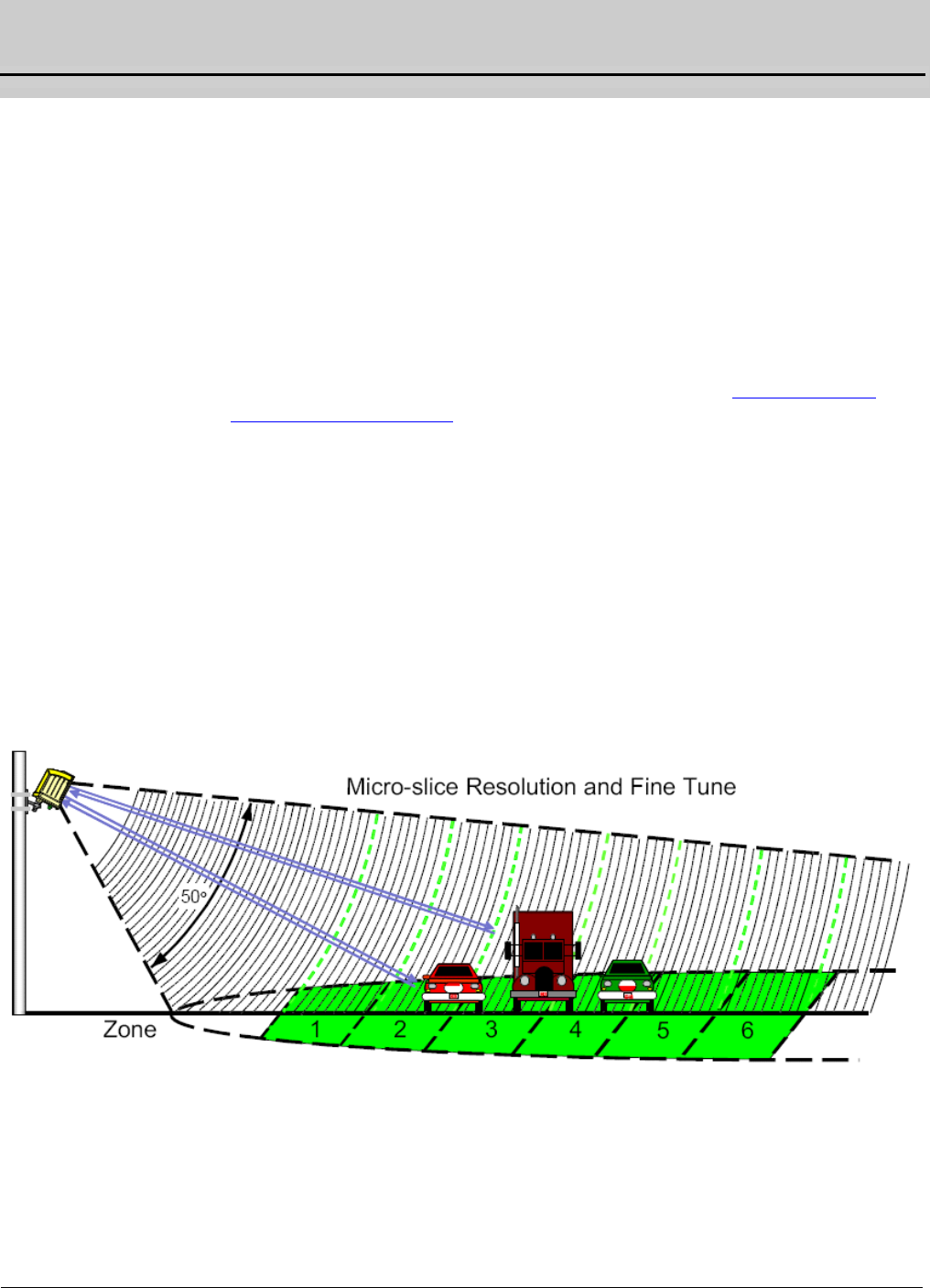
The Autoscope RTMS Sx-300 is a true RADAR device, designed for traffic sensing
applications. It measures the distance to objects in the path of its microwave beam.
The ranging capability allows the Autoscope RTMS Sx-300 to detect stationary and
moving vehicles in multiple detection zones. When pointed onto a roadway, the
Autoscope RTMS Sx-300 microwave beam projects an oval footprint. Its range is
divided into multiple micro-slices, in which vehicles are detected.
The Autoscope RTMS Sx-300 receives reflected signals from all surfaces within its
beam; pavement, barriers, vehicles and trees. Vehicles are detected when their
reflected signal exceeds the background level in their micro-slice by a certain
threshold. If that detection is part of a defined zone, its contact (optional) is closed
during the detection period to indicate detection.
Figure 1-1: Beam Range and Micro-Slices
Multiple operating modes optimize internal parameter settings for highway (mainly
free flowing traffic) and urban (mainly congested traffic) applications. A user can
select how the Autoscope RTMS Sx-300 is configured by setting these modes in the
Autoscope RTMS Setup Utility.
Chapter 1: Vehicle Detection
RTMS Sx-300 User Guide ©2014 Image Sensing Systems Inc. 1-2
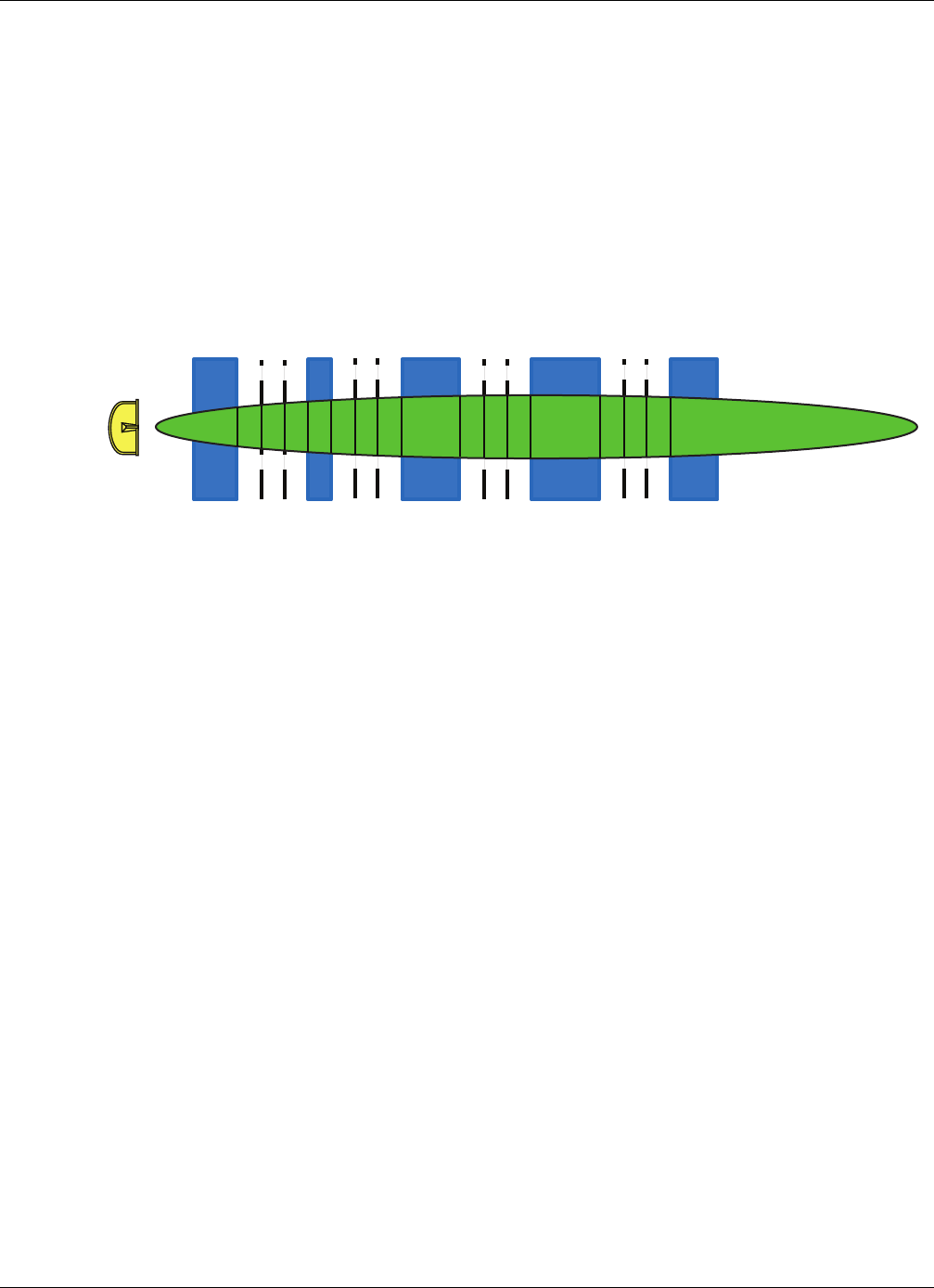
For mounting:
•The Autoscope RTMS Sx-300 is located on a roadside pole and is aimed
perpendicular to the traffic lanes.
•Micro-slices corresponding to the location of traffic lanes are allocated as
detection zones during the setup process.
•Each detection zone consists of multiple micro-slices.
•The length of the detection zone is determined by the width of the beam's
footprint.
Figure 1-2: Autoscope RTMS Sx-300 Footprint
Vehicle Detection
Autoscope RTMS Sx-300 technology allows accuracy in the following conditions,
even with a relatively low mounting-height:
•Severe weather and fog
•At night
•Strong vibrations common to roadways that carry large vehicles
•When vehicles are completely occluded by other vehicles
RTMS Sx-300
123 456 789 101112

Chapter 1: Autoscope RTMS Sx-300 Options
RTMS Sx-300 User Guide ©2014 Image Sensing Systems Inc. 1-3
Autoscope RTMS Sx-300 Options
The standard Autoscope RTMS Sx-300 model offers the following:
•K-band (24.125 GHz)
•Low Voltage Power 12-24 VAC or DC
•Eight MB Internal Data Storage Memory
•Serial RS-232/485
•Bluetooth Wireless
Additional models of the Autoscope Sx-300 that are available include:
•Autoscope Sx-300 TCP (base unit with TCP/IP Ethernet)
•Autoscope Sx-300 SSP (base unit with Second Serial Port and Contact
Closure)
For information about these options, see the Autoscope RTMS Sx-300 Optional
Configurations User Guide (PN A900-1155-2).
Autoscope RTMS Sx-300 Technical Specifications
Table 1-1: Mechanical Specifications
Measurement Dimensions
Enclosure Dimensions 23x18x17cm (9x7.25x6.75 in.)
Enclosure Weight
(Without mount)
1.02kg (2.24 lbs)
Enclosure Material Polycarbonate
Ingress Protection IP-67
Mounting Chromate conversion per MIL-C-5541, Type II, Class
1a on cast aluminum bracket capable of supporting a
load of up to 9.1 kg (20 lbs). (Vertical or horizontal).
Allowable pole flexing Less than 5 degrees

Chapter 1: Autoscope RTMS Sx-300 Technical Specifications
RTMS Sx-300 User Guide ©2014 Image Sensing Systems Inc. 1-4
Table 1-2: Power Specifications
Component Details
Autoscope RTMS Sx-300
standard power requirement
12-24 VAC or DC (see the “Power
Considerations” on page 2-1.
Polarity protection Not polarity sensitive
Over-voltage shutdown limit 34 VDC or 24 VAC
Recommended fusing (external) 2A slow blow minimum
Power consumption (Without
optional equipment)
3 Watts
Automatic recovery from power
failure
Within 20 seconds
Surge Immunity EN 61000-4-4 and EN 61000-4-5 (see
Appendix B: “Surge Protection”)
Table 1-3: Microwave Signal and Coverage Area Specification
Specification All RTMS Sx-300 Models
Center Frequency 24.125 GHz
Bandwidth 50 or 75 MHz (depending on settings)
Power Output 20 dBm EIRP
Beam Width: Vertical (Elevation) 50°
Beam Width: Horizontal (Azimuth) 12°
Side Lobes Suppression less than -20 dB
Range 0 – 76 m (0 – 250 ft)
Number Of Detection Zones (Lanes) 12

Chapter 1: Autoscope RTMS Sx-300 Technical Specifications
RTMS Sx-300 User Guide ©2014 Image Sensing Systems Inc. 1-5
*Accuracy Performance Conditions
Error performance parameters outlined above are achieved under normal, high-flow
traffic conditions and are subject to proper installation and setup. Lower accuracy is
expected under the following conditions:
•Low speed, high congestion conditions: The Autoscope RTMS Sx-300 tends
to be less accurate under very low speed conditions.
•Improper selection of installation site: insufficient set-back, height beyond the
recommendation, obstruction by barriers or high fences before monitored
lanes.
•Improper fine tune setting for the road geometry (lane width, barriers, etc.)
will result in “splashing” and therefore, over-counting.
•Large trucks may occlude smaller vehicles. If there is a high number of trucks
in traffic, the potential of occlusion increases, which may affect accuracy.
Table 1-4: Accuracy of Measurement & Error Rates
Measurement % Error *
Per Lane Volume: Side-Fired 5%
Volume Range 0 – 65535
Per Lane Occupancy: Side-Fired 5%
Occupancy Range & Resolution 0-100%, 0.1%
Per Lane Classification By Length
(6 classes)
10%
Class Lengths Limits range and
resolution
25.5 m, 0.1 m (83.6 ft, 0.3 ft)
Average Vehicle Speed: Side-Fired 10%
Speed range and resolution 0 – 160 Km/h, 1.6 Km/h (100 mph, 1 mph)
Resolution of time events 1.25 mS
Voltage readout resolution 0.1v

Chapter 1: Environmental Conditions
RTMS Sx-300 User Guide ©2014 Image Sensing Systems Inc. 1-6
Environmental Conditions
Note, printed circuit boards are conformally coated for protection against humidity
and corrosion.
Electromagnetic Interference
Certified under US FCC Rule part 15 Class B; Canadian CSA C108.8 M1983 Class A;
CE. For additional information, see “Preface” on page vii.
Upgrade Capability
User upgrades of firmware are available. Units can be upgraded through either direct
or remote connection. Direct connection is done using the RS-232/485 connection at
the site. If going to the site is not feasible, the Autoscope RTMS Sx-300 does support
remote firmware upgrade through our optional communications modules (see
“Autoscope RTMS Sx-300 Options” on page 1-3). If the remote communication link
is unstable, it is recommended that you use the direct connection method.
Table 1-5: Environmental Conditions
Item Operating Limits Shipping & Storage
Temperature
Range
-37 to +74°C (-35 to 165°F) -40° to 77°C (-40° to 171°F)
Humidity Up to 95% Relative Humidity Up to 95% Relative Humidity
Vibration 0.5 g up to 30 Hz
Shock 10 g peak for 11 ms
Wind Winds up to 139 km/h (120
MPH)
Precipitation Up to 100 mm/h

RTMS Sx-300 User Guide ©2014 Image Sensing Systems Inc. 2-1
Chapter 2: Hardware Installation
General
This chapter describes the installation and set up of the hardware components of the
Autoscope RTMS Sx-300.
Safety Information
Please review the following information before installation.
•Read all instructions before using.
•Heed all warnings in these instructions.
•Save these instructions for future reference.
•Autoscope RTMS Sx-300 units must be installed and adjusted in accordance
with the installation instructions contained in this manual.
•Use the Autoscope RTMS Sx-300 only for its intended purposes as described
in this manual. Changes or modifications not expressly approved by the
manufacturer could void the user's authority to operate the equipment.
•Consult Technical Support before using the Autoscope RTMS Sx-300 or other
Autoscope RTMS Sx-300-related products for any purpose not expressly
described in this manual or any other Autoscope RTMS Sx-300 product
manual. Do not use the Autoscope RTMS Sx-300 to control or operate a
gate-opening mechanism. Use of the Autoscope RTMS Sx-300 for any
unauthorized purpose may cause injury to personnel or damage to equipment.
•For optimal accuracy, it is strongly recommended that only trained personnel
survey the sites and install all Autoscope RTMS Sx-300-related products.
•For more information about our installation, surveying, and training
programs, contact your Autoscope RTMS Sx-300 sales representative.
Pre-Installation Considerations
The following information on power, cabling and communications should be taken
into consideration prior to installing the Autoscope RTMS Sx-300.
Power Considerations
The Autoscope RTMS Sx-300 is a constant power device that requires in its basic
configuration 3 watts of power. Electrical power has two components, voltage and
current; both must be available in the correct ranges to operate the Autoscope RTMS
Sx-300. The voltage must be between 12 and 24 volts (DC or AC RMS) with the
voltage level read at the Autoscope RTMS Sx-300. Voltages below 12 volts will be
insufficient to power the Autoscope RTMS Sx-300; voltages above 24 volts will cause
the Autoscope RTMS Sx-300 to shut down to protect itself from an overvoltage
condition. Losses in the cable must be addressed in setting the voltage to be supplied
to the unit.

Chapter 2: Pre-Installation Considerations
RTMS Sx-300 User Guide ©2014 Image Sensing Systems Inc. 2-2
Current in sufficient quantity must be available: at 12 volts, the Autoscope RTMS
Sx-300 will draw 250 mA of current; at 24 volts 125 mA (base model, higher for units
with additional communications options). Using an adaptor that provides 12 volts and
100 mA of current means that the total power to the Autoscope RTMS Sx-300 will be
12*0.1 = 1.2 watts, or roughly 40% of the power needed to turn on the Autoscope
RTMS Sx-300.
On power up, there will be an inrush current that will be several times higher than the
operating current. The power supply must be able to handle this temporary current
flow. If the power supply is unregulated (such as a simple step-down supply from 120
VAC to 24 volts (AC or DC)), the output voltage may be higher than specified when
the current draw is less than maximum available from the supply This may cause the
Autoscope RTMS Sx-300 to sense an overvoltage condition and shut down to protect
itself.
If additional hardware (such as optional communications modules) is added to the
Autoscope RTMS Sx-300, the power required to operate the Autoscope RTMS Sx-300
will increase. The voltage seen by the Autoscope RTMS Sx-300 will remain the same,
but the current will increase to meet the new power requirement.
Cabling Considerations
The design of an Autoscope RTMS Sx-300 installation should include a breakout box
close to the Autoscope RTMS Sx-300 that can be used for setup and maintenance
purposes, and can include surge suppression circuitry and external communications
devices as required. Reference designs are available. For additional information see
Appendix A: “Cabling and Connectors” and Appendix B: “Surge Protection”.
Communications Considerations
The communication method that comes standard on all Autoscope RTMS Sx-300
units is serial, which can be configured for RS-232 or RS-485 and Bluetooth. Port 1 is
the main port that is connected to the outside world, Port 2 (optional) can be installed
to also communicate with the outside world (for a complete list, see “Autoscope
RTMS Sx-300 Options” on page 1-3).
It is recommended that serial port 1 be accessible to field technicians for maintenance
purposes, even if the primary communication with the Autoscope RTMS Sx-300 will
use Port 2.
IMPORTANT: The serial port can support hardware handshaking. It is critical that
hardware handshaking (RTS/CTS) not be enabled by the software if
the corresponding wires are not installed in the cable. Enabling
RTS/CTS without the wires being in the cable will prevent the
Autoscope RTMS Sx-300 serial port from communicating.

Chapter 2: Placement in Side-Fired Highway Configuration
RTMS Sx-300 User Guide ©2014 Image Sensing Systems Inc. 2-3
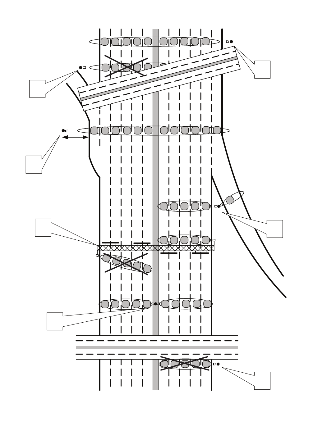
Placement in Side-Fired Highway Configuration
Autoscope RTMS Sx-300 is designed to mount on existing poles and road structures.
Figure 2-1 shows typical cases of Autoscope RTMS Sx-300 side-fired/highway sites.
The design considerations for each case are:
•Case 1 — Maximal utilization of the Autoscope RTMS Sx-300 zone
capability. Limitations are as follows:
– A 12-zone coverage requires a larger setback (the distance to the first
lane. If setback is insufficient, two Autoscope RTMS Sx-300 units may be
required (see “Height and Setback Requirements” on page 2-5).
– Limitations in mapping range slices to lanes will cause decreased
accuracy. The site designer must weigh the trade-off between required
level of accuracy and cost.
– In almost all cases, the Autoscope RTMS Sx-300 can resolve the barrier
return signal from that of the vehicles in the lane immediately behind it as
long as 50% of vehicle can be seen (see “Guardrails and Barriers” on
page 2-8).
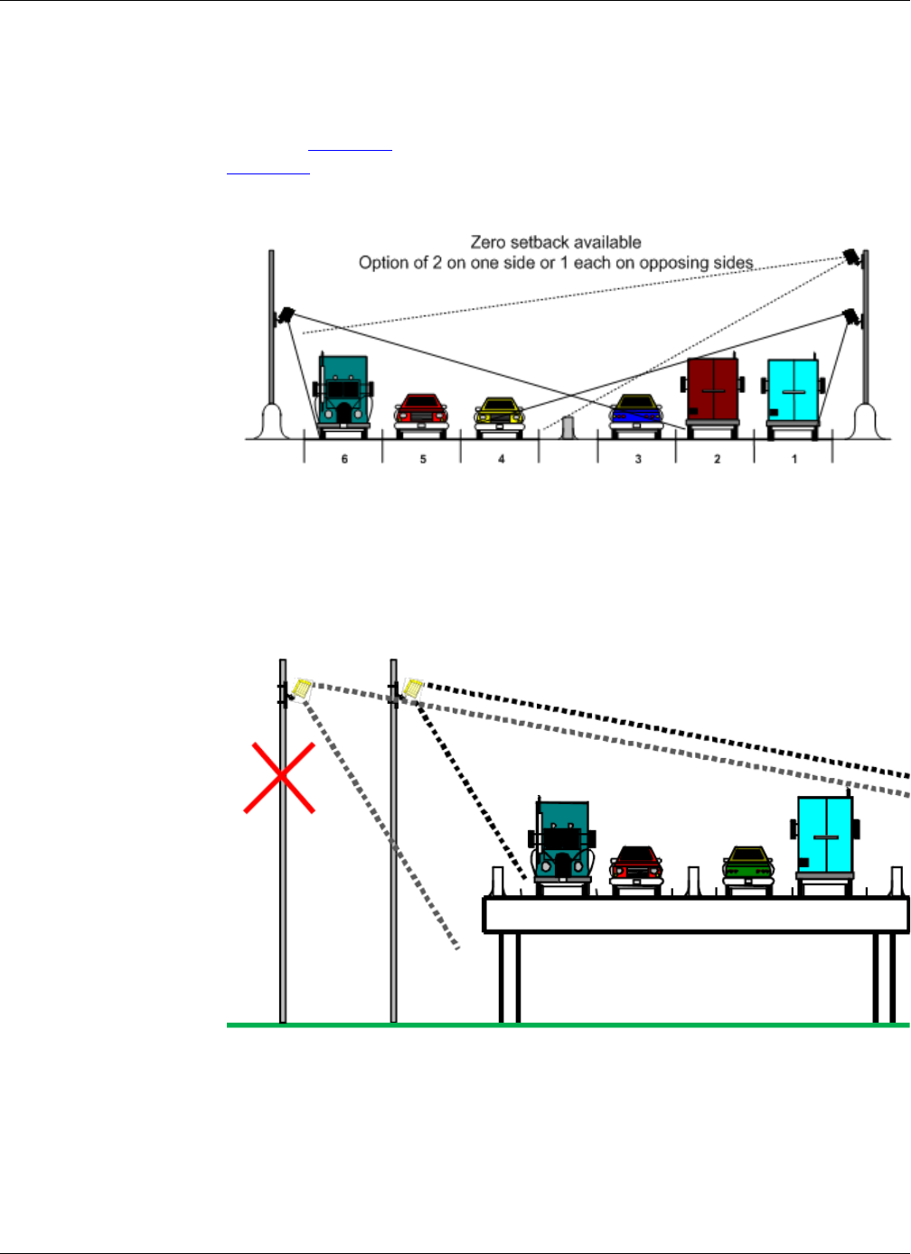
•Case 2 — Overpass installations: Do not mount the Autoscope RTMS Sx-300
on a perpendicular overpass. Instead, use poles located at least 5 m (17 ft)
from the overpass to avoid multi-path. Multi-path is a situation in which the
reflected signals from vehicles can also reach the Autoscope RTMS Sx-300
by a secondary reflection from a large flat surface (such as a sign or overpass).
If the overpass is at an angle to the road, take advantage of the angle to point
the Autoscope RTMS Sx-300 at the monitored roadway and away from the
overpass. Do not aim the beam under it.
•Case 3 — Using median poles to mount two Autoscope RTMS Sx-300
sensors, one per direction may save poles but the designer should verify
available set-back (see “Height and Setback Requirements” on page 2-5).
•Case 4 — Sign-structure installations (see “Installing Autoscope RTMS
Sx-300 on Sign Structures” on page 2-10).
•Case 5 — Typical ramp metering site.
Chapter 2: Placement in Side-Fired Highway Configuration
RTMS Sx-300 User Guide ©2014 Image Sensing Systems Inc. 2-4
Figure 2-1: Autoscope RTMS Sx-300 Side-Fired Highway Sites
2
3
45
2
2
Setback
1
Chapter 2: Placement in Side-Fired Highway Configuration
RTMS Sx-300 User Guide ©2014 Image Sensing Systems Inc. 2-5
Height and Setback Requirements
The Autoscope RTMS Sx-300 has a detection area of 76 m (250 ft), and is able to
detect up to 12 lanes of traffic within that distance. Make sure that all lanes of traffic
are within 76 m (250 ft) of the Autoscope RTMS Sx-300.
Setback is the distance between the nearest edge of the first lane of traffic to be
monitored and the front of the structure on which the Autoscope RTMS Sx-300 is
mounted. Setback is a limiting installation parameter of the Autoscope RTMS Sx-300.
More lanes can be covered with a larger setback.
Zero Setback The Autoscope RTMS Sx-300 has the ability to detect vehicles in lanes with zero
setback, i.e., pole location immediately beside the first lane of detection. Many
Midblock detection sites, as well as bridges, have limited setback.
Figure 2-2: Zero Setback
Zero setback operation is limited to a maximum of four lanes and the mounting height
would be approximately 4 m (14 ft).
It is always recommended to obtain as much setback as possible as this may improve
the overall detection. The zero setback feature is available with all RTMS Sx-300
units and should only be used if the situation dictates. Where significant setback is
available please refer to the standard installation charts.
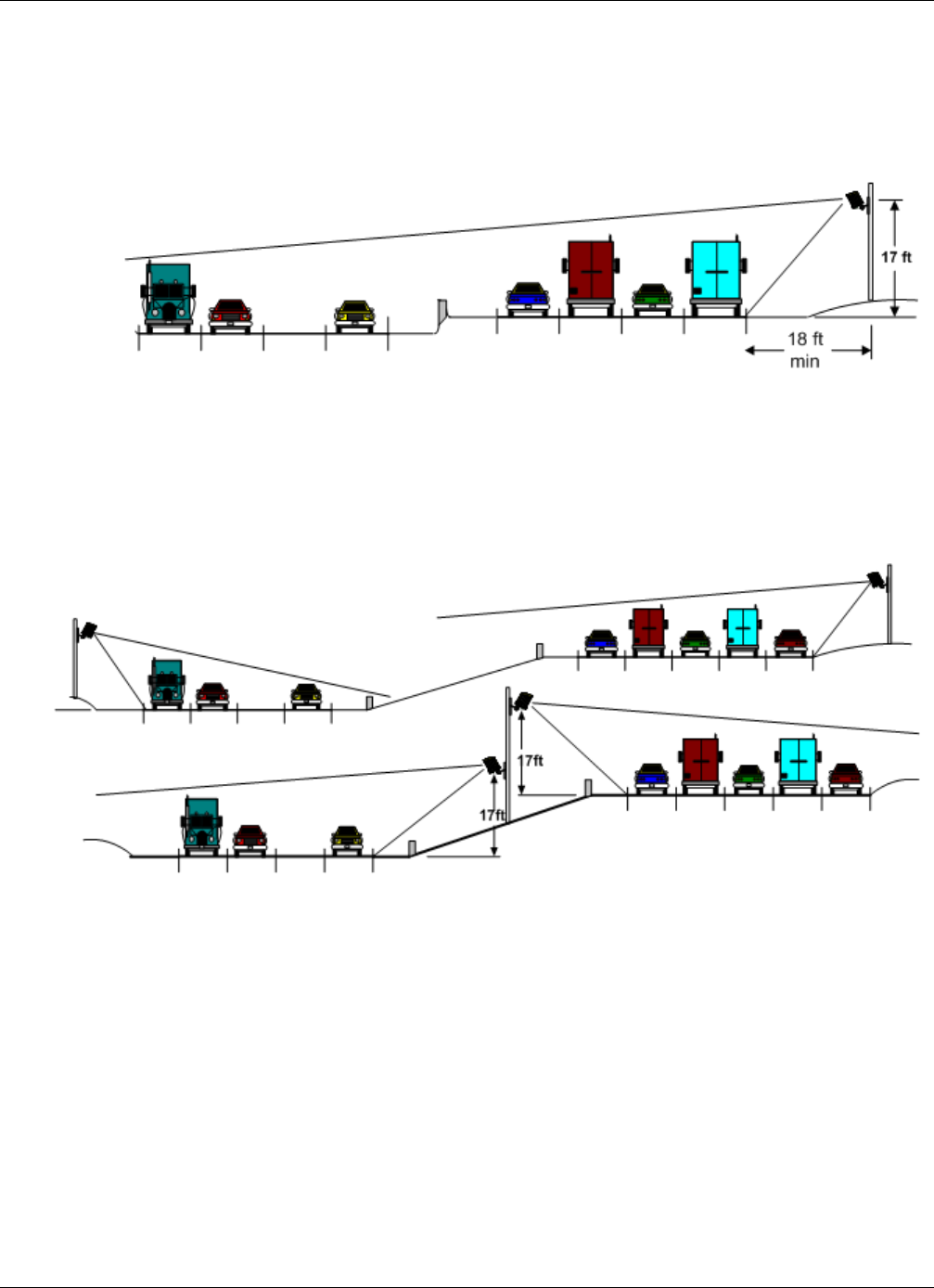
Standard Setback The Autoscope RTMS Sx-300 should be mounted at a minimum height of 5 m (17 ft)
to minimize occlusion of vehicles even by the tallest trucks.
It must be set back from the first monitored lane to ensure it includes all required lanes
within its field of view. The amount of setback varies with the width of the road to be
covered.
Use the diagrams in Figure 2-3, Figure 2-4, and Figure 2-5 to determine the setback
required to monitor a given number of lanes. The correct installation height can be
determined once the setback is set. Height is measured relative to the road surface of
the detection area. Do not measure height from the bottom of the mounting pole.
Chapter 2: Placement in Side-Fired Highway Configuration
RTMS Sx-300 User Guide ©2014 Image Sensing Systems Inc. 2-6
NOTES:
•It is almost always better to be further back from the minimum. If clear space
is available, move the Autoscope RTMS Sx-300 further back.
•The mounting height is based on the setback. Using the correct height value
allows the Autoscope RTMS Sx-300 to be aimed so that it receives maximum
return signal while covering all required lanes. Mounting the Autoscope
RTMS Sx-300 at an incorrect height will reduce accuracy.
•Widths of roadway medians must be included in the total detection area. For
example: You may be able to set up 12 zones, but they must be within 76 m
(250 ft).
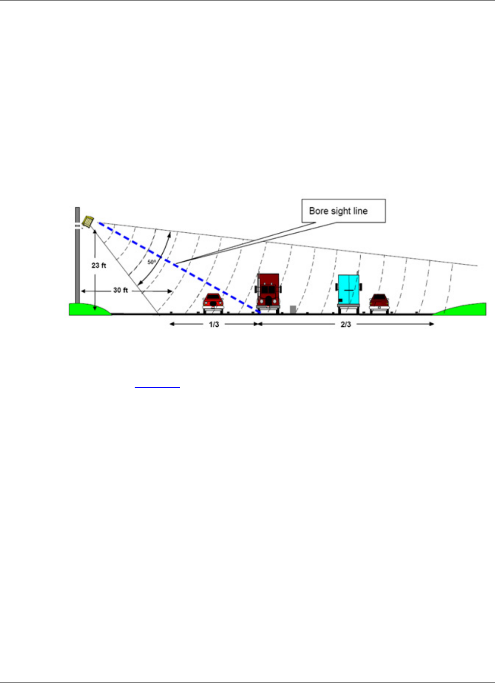
Figure 2-3: Autoscope RTMS Sx-300 Initial Aiming
The amount of setback you have will determine your actual detection area. As shown
in Figure 2-2, a setback of 0 to 1.6 m (0 to 5 ft) will allow the Autoscope RTMS
Sx-300 to detect vehicles up to about 15 m (50 ft). A setback of 7 m (23 ft) allows the
Autoscope RTMS Sx-300 to detect vehicles up to 61 m (200 ft) of the Autoscope
RTMS Sx-300.

Chapter 2: Placement in Side-Fired Highway Configuration
RTMS Sx-300 User Guide ©2014 Image Sensing Systems Inc. 2-7
Figure 2-4: Setback Distance Chart
A setback greater than the minimum is desirable if room is available. Set the proper
mounting height based upon actual setback distance.
Figure 2-5: Mounting Height Chart.
30
29
28
27
26
25
24
23
22
21
20
19
18
17
16
15
14
13
12
11
10
9
8
7
6
5
12
24
36
48
60
72
84
96
108
120
132
144
156
168
180
192
204
216
228
240
250
9.1
8.8
8.5
8.2
7.9
7.6
7.3
7.0
6.7
6.4
6.1
5.8
5.5
5.2
4.9
4.6
4.3
4.0
3.7
3.4
3.1
2.8
2.5
2.2
1.9
1.6
Setback (Feet)
Setback (Meters)
Detection Area (Feet)
3.6
7.3
11
14.6
18.2
22
35.6
29.3
33
36.6
40.2
43.9
47.5
51.2
54.9
58.5
62.2
65.8
69.5
73.2
76
Detection Area (Meters)
30
29
28
27
26
25
24
23
22
21
20
19
18
17
9.1
8.8
8.5
8.2
7.9
7.6
7.3
7.0
6.7
6.4
6.1
5.8
5.5
5.2
Mounting Height (Feet)
Mounting Height (Meters)
5 10 12 14 16 18 20 22 24 26 28 30 32 34 36 38 40 42 44
1.5 3.1 3.7 4.3 4.9 5.5 6.1 6.7 7.3 7.9 8.5 9.1 9.7 10.3 10.9 11.5 12.1 12.7 13.3
Setback (Feet)
Setback (Meters)
Chapter 2: Placement in Side-Fired Highway Configuration
RTMS Sx-300 User Guide ©2014 Image Sensing Systems Inc. 2-8
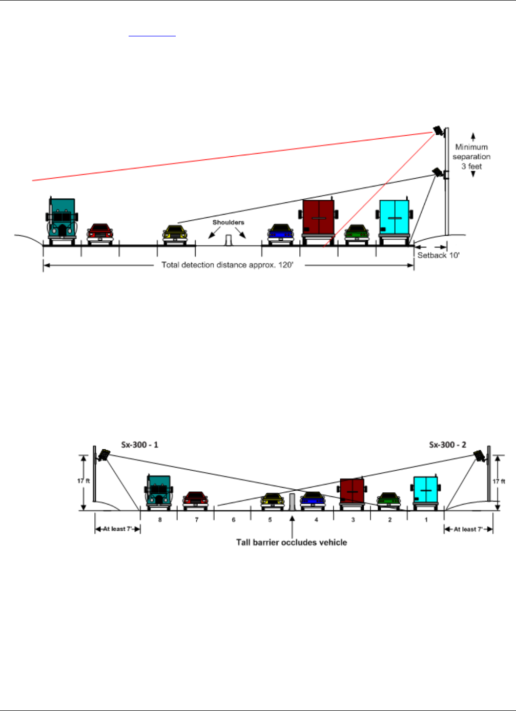
Figure 2-6 shows the effect of restricted setback on the number of lanes that can be
monitored by a single Autoscope RTMS Sx-300. Depending on the total area of
detection required and the available setback the need for a second unit may be
required. The same pole can be used to install the unit; however, a minimum of 1 m
(3.3 ft) is required between the units.
Figure 2-6: Effect of Low Setback
Guardrails and Barriers
In almost all cases, median guard-rails or barriers do not interfere with traffic
detection. In the few cases in which such interference may occur, e.g., large metal
barrier, very tall barriers or movable metal fences, a good solution is to use a second
sensor on the other side of the road. Each of the sensors can monitor lanes on its side
of the barrier, requiring a smaller setback to cover fewer lanes, as shown below.
Figure 2-7: Two-Sided Placement
Chapter 2: Placement in Side-Fired Highway Configuration
RTMS Sx-300 User Guide ©2014 Image Sensing Systems Inc. 2-9
Elevated Roadway
On elevated or sunken roadways with insufficient outside shoulders, it may be an
impossible job for a single sensor. Two Autoscope RTMS Sx-300 units, configured as
shown by Figure 2-8, will cover all lanes if detection zones are defined as shown in
Figure 2-8.
Figure 2-8: Autoscope RTMS Sx-300 on Elevated Roadway
Autoscope RTMS Sx-300 can also monitor elevated highways from tall poles erected
on the lower level. However, in this case the setback should be less than 8 m (26 ft), to
avoid the strong reflection from the side of the structure.
Figure 2-9: Pole Location for an Elevated Roadway
Chapter 2: Placement in Side-Fired Highway Configuration
RTMS Sx-300 User Guide ©2014 Image Sensing Systems Inc. 2-10
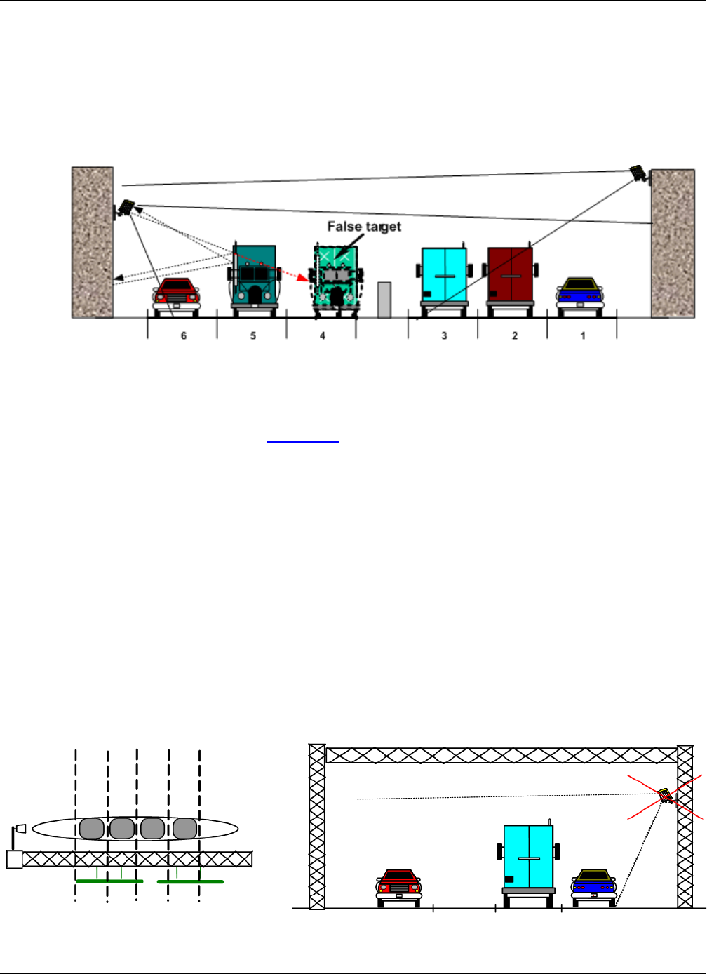
Sunken Road and Roadside Walls
When vertical surfaces reflecting microwaves (e.g., dense chain link fences or
retaining walls of a sunken roadway) are present, multi-path reflections from large
vehicles in close lanes cause additional false (ghost) detection in farther detection
zones.
Figure 2-10: False Target Generated by Fence Or Wall
To avoid this problem install the Autoscope RTMS Sx-300 higher and increase the
elevation angle to detect the far lanes of traffic excluding the nearest lanes, as shown
on the right in Figure 2-10.
Installing Autoscope RTMS Sx-300 on Sign Structures
The installation of the Autoscope RTMS Sx-300 on Message Sign structures is
acceptable only if the Autoscope RTMS Sx-300 is mounted to be offset from the
overhead span of the structure. Structures can reflect the microwave signal and distort
the accuracy of detection. Some structures such as DMS units have very wide, flat
metal bottoms to the structure that are similar in nature to bridges, these type can
cause more interference than other lattice work type structures and may require
consultation with Autoscope RTMS Sx-300 Technical Support.
The best way to mount the Autoscope RTMS Sx-300 is to place a horizontal mast arm
or pipe approximately 1.3 m (4 ft) away from the structure (1.8-2.4 m [6-8 ft] if
DMS), ideally on the back of the structure away from any lighting or signs. Ensure the
detector is aimed perpendicular to the traffic flow.
Figure 2-11: Autoscope RTMS Sx-300 on Sign Structures
Chapter 2: Placement in Side-Fired Highway Configuration
RTMS Sx-300 User Guide ©2014 Image Sensing Systems Inc. 2-11
Grade Differentials
When grade differences are small, a single unit on the high side may work, provided
all lanes are within range.
Figure 2-12: Small Grade Differentials
When the grade differential is large enough to put a part of the lower level in a
“shadow”, two Autoscope RTMS Sx-300 units are required as shown by the
following.
Figure 2-13: Large Grade Differential
Trees
Trees and bushes in the path of the microwave beam (in the setback or in medians)
must be avoided. Autoscope RTMS Sx-300 units must be relocated or a gap in
vegetation maintained in the path of the beam.
Chapter 2: Placement in Midblock Applications
RTMS Sx-300 User Guide ©2014 Image Sensing Systems Inc. 2-12
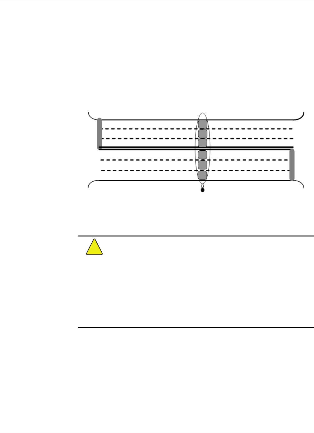
Placement in Midblock Applications
Placement in Midblock application is similar to Side-fired Highway. If sufficient
setback is available, up to 12 zones of traffic can be configured. If the Autoscope
RTMS Sx-300 is mounted in a zero setback configuration, only the nearest four zones
are available for detection; however, the nearest zones can be excluded from detection
(creating adequate sensor setback) if data from zones farther away is desired. The
installer should verify which intersection approaches are most critical to proper data
collection and configure the Autoscope RTMS Sx-300 to capture information from
these lanes of traffic.
Figure 2-14: Midblock Placement
Mounting and Aiming Procedure
Warning
!
Installation of Autoscope RTMS Sx-300 hardware may require that you work
above the ground on a ladder or bucket truck. Please make sure you have all the
required equipment and are aware of potential safety issues before starting any
installation. DO NOT install any Autoscope RTMS Sx-300 hardware if you are
unsure how to complete the installation or lack appropriate safety equipment. It
is recommended that you do NOT install this hardware during inclement
weather.
The following equipment is required to mount and aim the Autoscope RTMS Sx-300
unit:
•Provided: Autoscope RTMS Sx-300 unit, bracket, washers, nut and bolts (for
brackety only) and connectors or optional pre-made Autoscope RTMS Sx-300
cable.
•Not Provided: Bolts or stainless steel banding to mount to a pole. The bolt
specifications depend on the mounting requirements: for example, different
bolts may be required when the Autoscope RTMS Sx-300 unit is mounted on
a wooden pole than when the Autoscope RTMS Sx-300 unit is mounted on a
Chapter 2: Mounting and Aiming Procedure
RTMS Sx-300 User Guide ©2014 Image Sensing Systems Inc. 2-13
concrete wall. 7/16” wrench, 1/2” wrench, assorted tools to be determined by
mounting specifications.
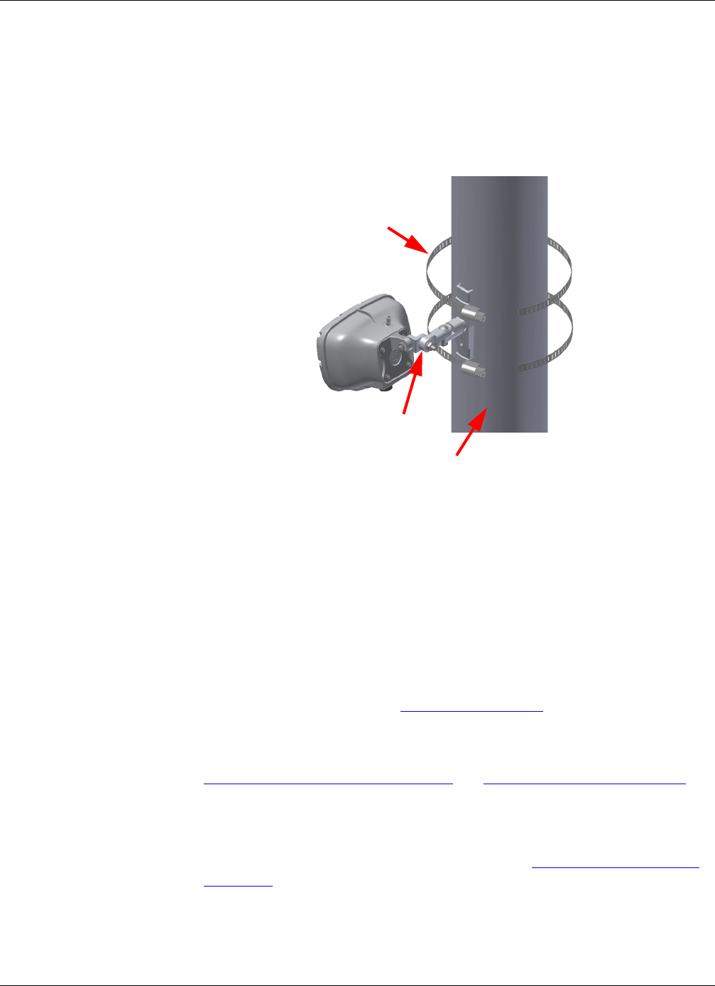
To mount and aim the Autoscope RTMS Sx-300 sensor, do the following.
1. Attach the bracket to the roadside pole (or another specified location) using bolts
or stainless steel banding.
2. Secure the Autoscope RTMS Sx-300 to the mounting bracket using the washer,
lock washer and nut.
NOTE: Make sure that the cable connector is on the bottom of the unit when it is
mounted.
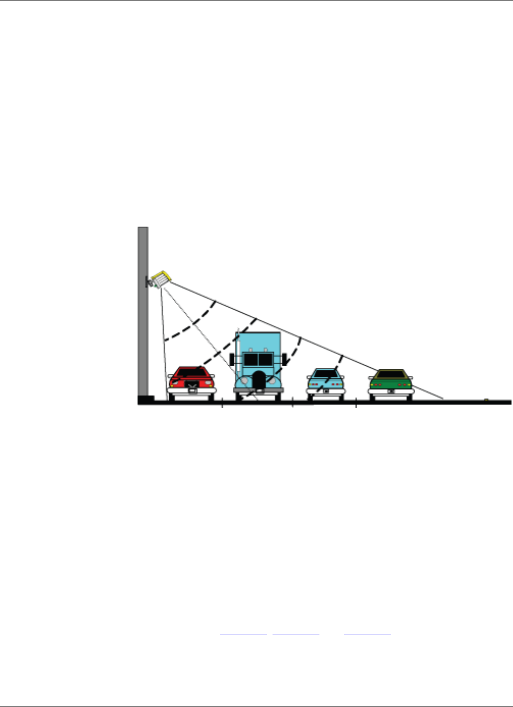
3. Adjust the Autoscope RTMS Sx-300 to be perpendicular to the travel lanes and
level side to side.
4. Look from behind the unit and use the top sight-ridge as a guide to align the bore
sight.
5. Tilt the Autoscope RTMS Sx-300 so that the top of the sensor is aimed to the first
1/3 of the monitored lanes (see Figure 2-3 on page 2-6).
6. Secure the position by tightening the nuts.
7. Connect the cables for power, communications and surge suppression (see
Appendix A: “Cabling and Connectors” and Appendix B: “Surge Protection”).
NOTE: Steps 3 and 6 are general guidelines. Actual mounting and tilt may need to be
adjusted based on multiple factors such as obstacles and number of lanes.
8. Configure the Autoscope RTMS Sx-300 sensor (see Chapter 4: “Configuration
and Setup”).
Stainless steel
banding
Mounting bracket
Mounting pole

RTMS Sx-300 User Guide ©2014 Image Sensing Systems Inc. 3-1
Chapter 3: RTMS Setup Utility
General
The Autoscope RTMS Setup Utility is the program that is used to interface with the
Autoscope RTMS Sx-300. It can communicate with a single Autoscope RTMS Sx-300
(Direct) or with multiple RTMS Sx-300 units (Multidrop) when they are on the same
communications channel and Polled Data Mode is active.
The application has numerous screens that you use to configure and operate the
system.
This chapter describes:
•how to install the Setup Utility.
•how to start the Setup Utility application.
•how to start the Setup Utility in Demo mode.
System Requirements
The Setup Utility must be installed on a computer that has the following:
•Operating System: Microsoft® Windows XP® operating system or Windows
7 operating system (32 or 64 bit)
•Software: Microsoft .NET Framework 3.5 SP1
•Hardware: Serial (preferred), or USB with a USB-to-serial adapter
NOTE: The Setup Utility runs with Microsoft .NET 2.0 and higher. Run the software
with Microsoft .NET 3.5.1 for optimal performance. In most cases the
software performs acceptably but you may notice visual differences in the
graphical user interface. A warning message is displayed if the .NET version
is incompatible. Click Ignore to proceed.
Chapter 3: Installing the Setup Utility
RTMS Sx-300 User Guide ©2014 Image Sensing Systems Inc. 3-2
Installing the Setup Utility
NOTE: If there are RTMS Sx-300 and RTMS G4 sensors in the network, you will
need to install the setup utility for both sensor types.
To install the Setup Utility, do the following.
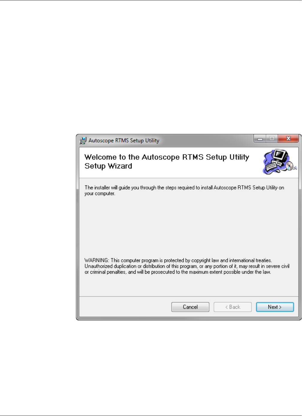
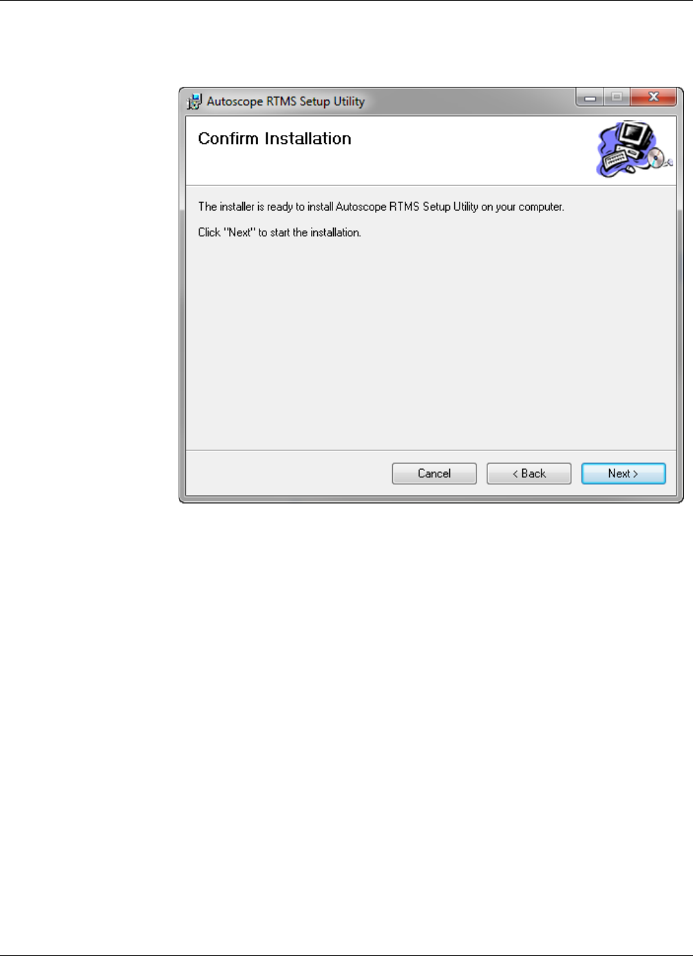
1. Locate and double-click the installation file:
•For RTMS Sx-300 sensors: Autoscope_RTMS_Setup Utility xxx.msi (xxx
is the version number).
•For RTMS G4 sensors: RTMS_Setup Utility xxx.msi (xxx is the version
number)
The following window appears.
2. Click Next.
Chapter 3: Installing the Setup Utility
RTMS Sx-300 User Guide ©2014 Image Sensing Systems Inc. 3-3
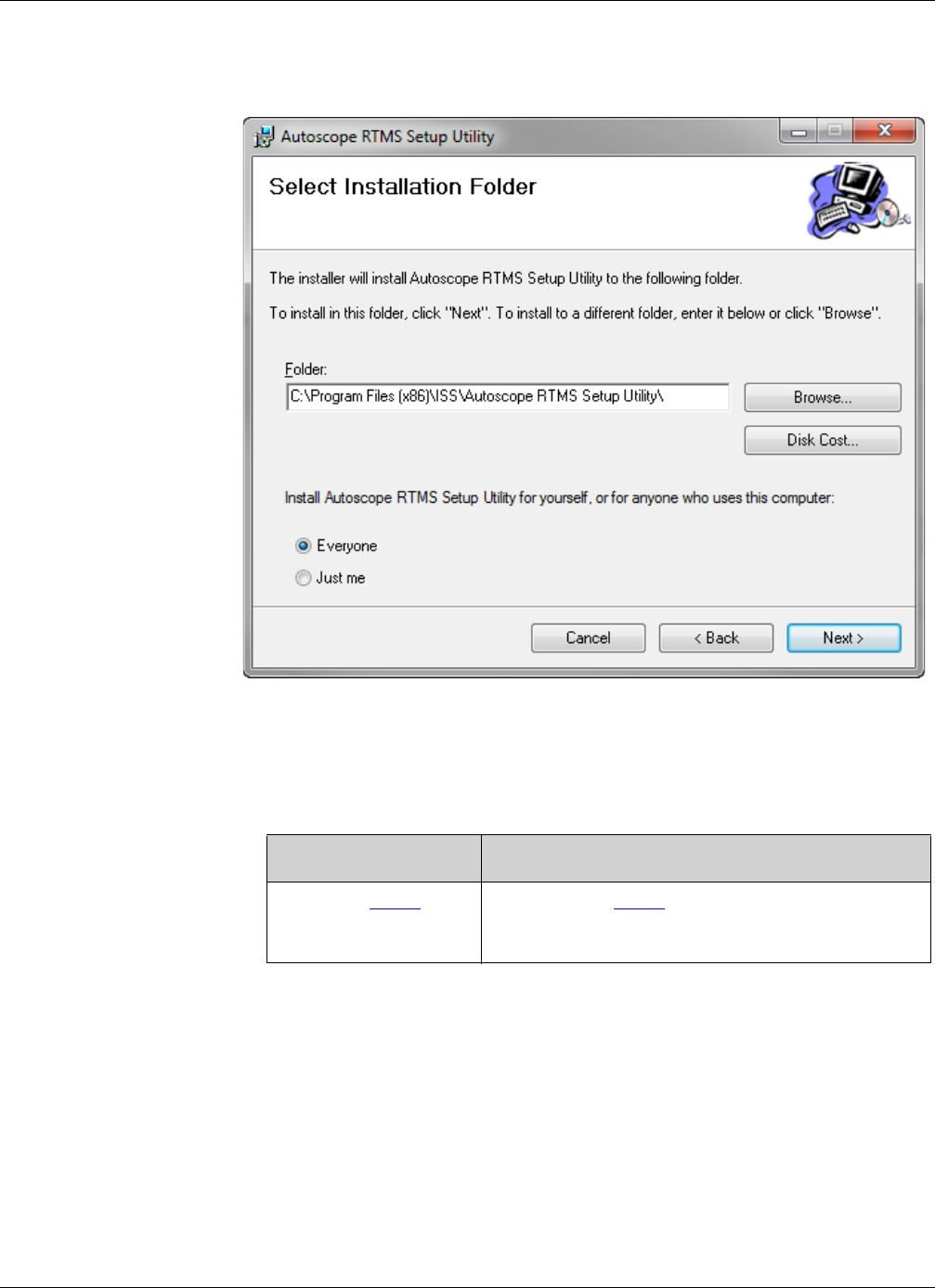
The following window appears.
3. Select whether you want only the logged in user to be able to access the setup
utility.
4. To see how much disk space is available on your system, click Disk Cost. . .
5. Do you want the files installed in the default location?
6. Click Browse.
Yes No
Proceed to Step 9 Continue with Step 6.
NOTE: The default location is recommended.
Chapter 3: Installing the Setup Utility
RTMS Sx-300 User Guide ©2014 Image Sensing Systems Inc. 3-4
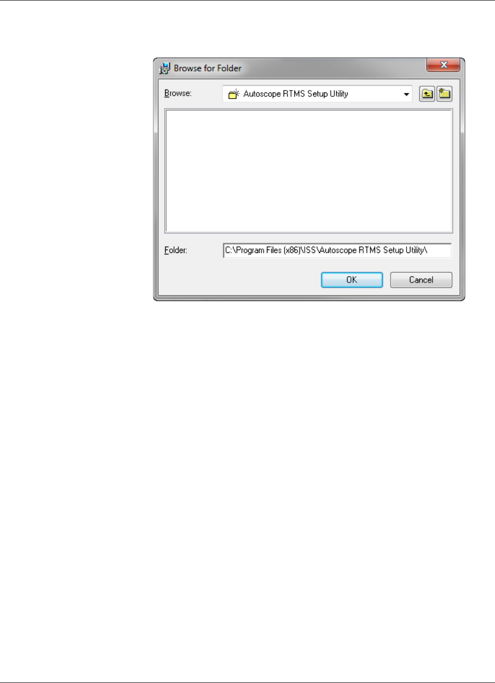
The following window appears.
7. Select a new location for the files to be installed.
8. Click OK.
9. Click Next.
Chapter 3: Installing the Setup Utility
RTMS Sx-300 User Guide ©2014 Image Sensing Systems Inc. 3-5
The following window appears.
10. Click Next.
Chapter 3: Installing the Setup Utility
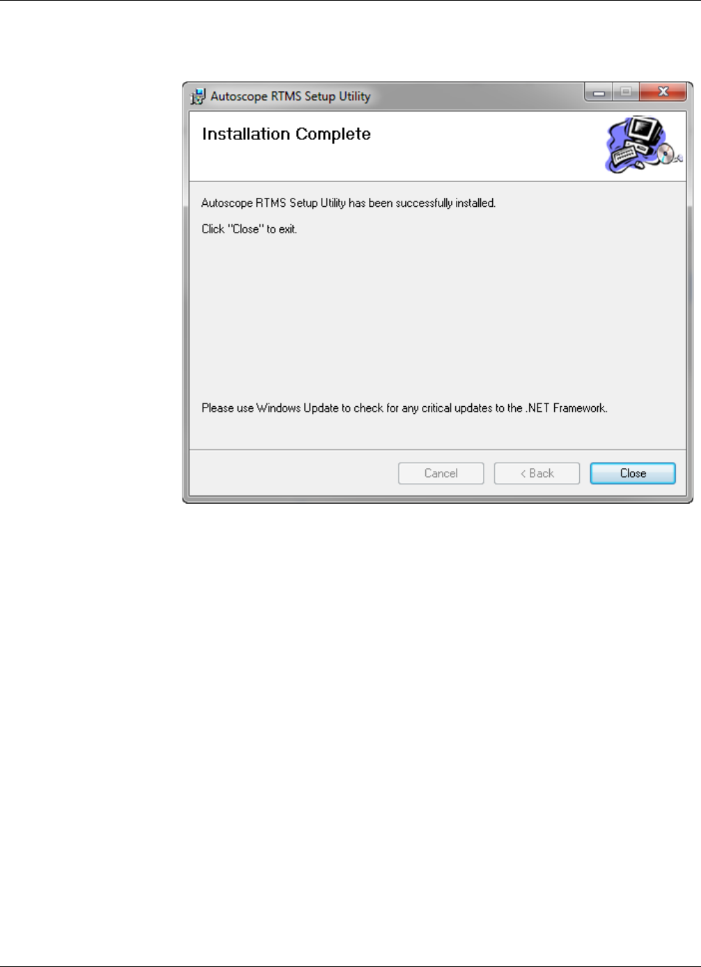
RTMS Sx-300 User Guide ©2014 Image Sensing Systems Inc. 3-6
When the installation is completed the following window appears.
11. Click Close.
An icon appears on your desktop as a shortcut to starting the Setup Utility
application.
Chapter 3: Starting the Setup Utility
RTMS Sx-300 User Guide ©2014 Image Sensing Systems Inc. 3-7
Starting the Setup Utility
IMPORTANT: Windows may disable the COM port if port activity is detected
during the boot process. DO NOT connect the Autoscope RTMS
Sx-300 to the COM port before Windows startup is complete.
How the setup utility is started is dependent on whether there are RTMS G4 sensors in
the network along with RTMS Sx-300 sensors.
For Networks With Only RTMS Sx-300 Sensors
To connect to the Autoscope RTMS Sx-300 and start the Setup Utility, do the
following.
1. Using a serial cable, connect the Autoscope RTMS Sx-300 to the serial port of the
computer that has the Setup Utility installed.
2. Power up the Autoscope RTMS Sx-300.
3. Select Start>All Programs>ISS>Autoscope RTMS Setup Utility>Autoscope
RTMS Setup Utility or double-click the shortcut icon on the desktop.
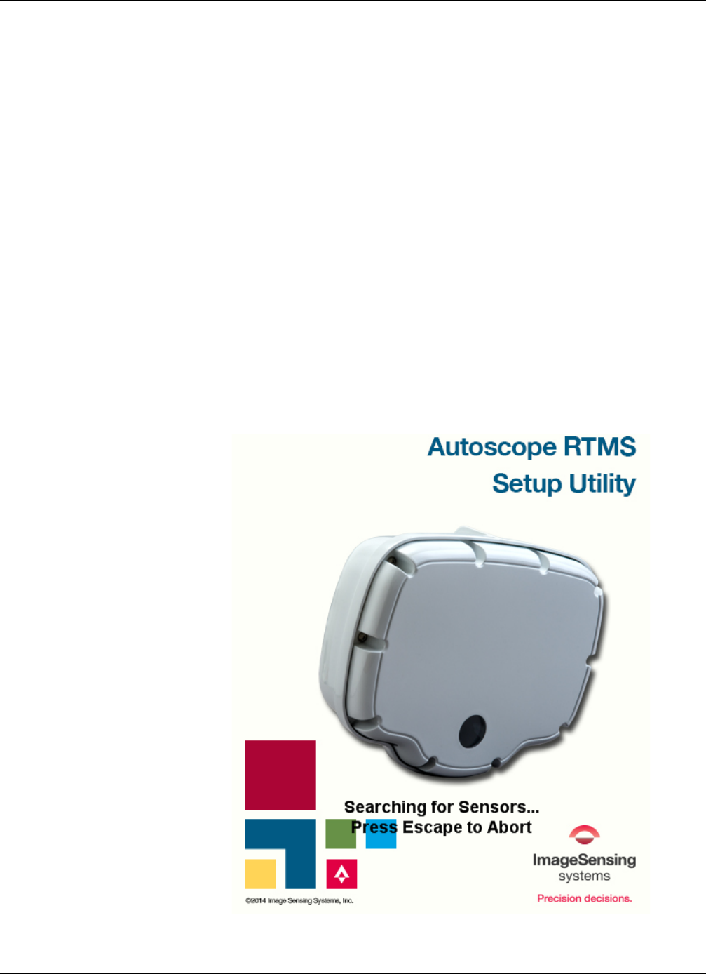
The following window appears.
Chapter 3: Starting the Setup Utility
RTMS Sx-300 User Guide ©2014 Image Sensing Systems Inc. 3-8
If communication is established with the Autoscope RTMS Sx-300 sensor, the
Main Screen will appear. If communication could not be established or if multiple
units are located, the Start screen will appear.
4. Did the Main Screen or Start screen appear?
Main Screen Start Screen
Main Screen Start Screen
The connection is established. Conduct a search for sensors (see
“Finding Sensors” on page 5-19).
Chapter 3: Starting the Setup Utility
RTMS Sx-300 User Guide ©2014 Image Sensing Systems Inc. 3-9
For Multidrop Networks With RTMS Sx-300 and RTMS G4 Sensors
To connect to the Autoscope RTMS sensors and start the Setup Utility, do the
following.
1. Using a serial cable, connect an Autoscope RTMS sensor to the serial port of the
computer that has the Setup Utility installed.
2. Power up the Autoscope RTMS sensor.
3. Select Start>All Programs>ISS>Autoscope RTMS Setup Utility>Autoscope
RTMS Setup Utility or double-click the shortcut icon on the desktop.
4. When the opening screen appears, press the ESC key.
The Start screen appears.
5. Conduct a search for sensors (see “Finding Sensors” on page 5-19).
Chapter 3: Navigating the Setup Utility
RTMS Sx-300 User Guide ©2014 Image Sensing Systems Inc. 3-10
Navigating the Setup Utility
The Setup Utility buttons and menus may be operated by any method listed below.
The terms select and click are used throughout this manual to describe actions you can
complete using the mouse or keyboard.
•The interface consists of buttons and text displays.
•Point and click to select a button.
•Navigate using up/down/left/right keys and ENTER keys. Select by the arrow
keys and take action by hitting ENTER.
•In some cases the TAB key can be used to navigate between the two main
panels.
For a complete description of the Main Screen, see “Main Screen” on page 3-19
Running Demo Mode
The following describes the procedure for operating the utility in demo mode.
NOTE: Before running Demo mode, verify that the computer is NOT connected to
an Autoscope RTMS Sx-300 unit.
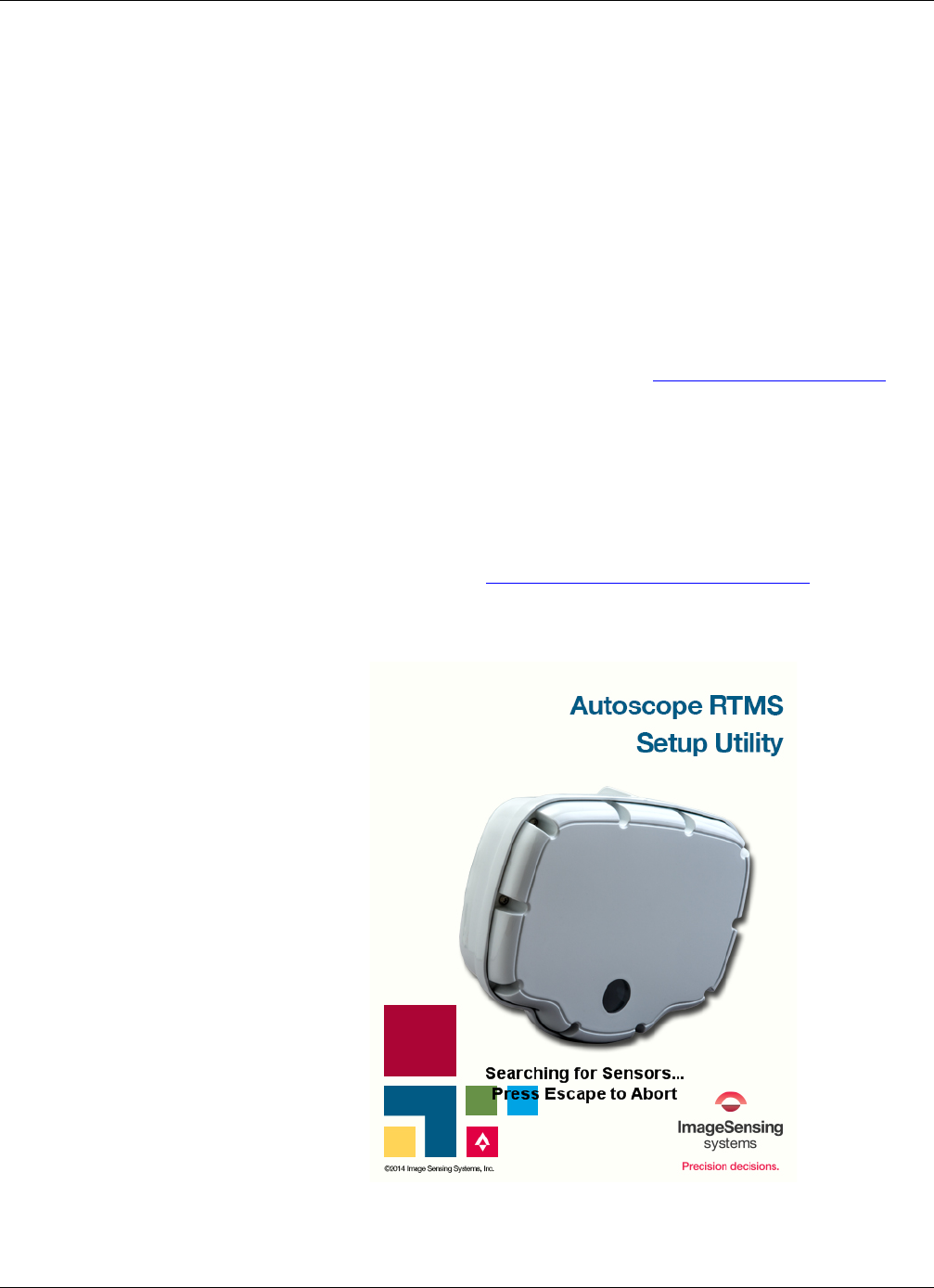
1. Start the Setup Utility; see “Starting the Setup Utility” on page 3-7.
The following screen appears.
2. Press the ESC key to halt the search.
Chapter 3: Running Demo Mode
RTMS Sx-300 User Guide ©2014 Image Sensing Systems Inc. 3-11
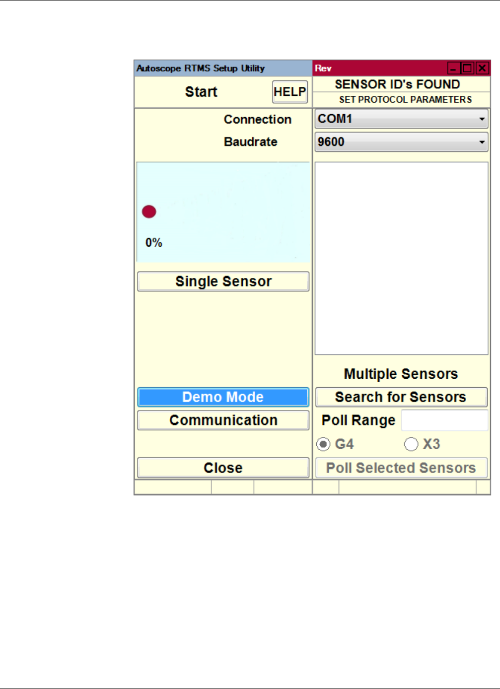
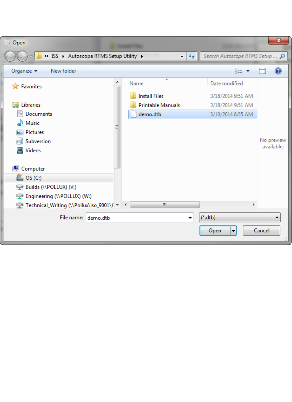
The Start screen appears.
3. Click Demo Mode.
Chapter 3: Running Demo Mode
RTMS Sx-300 User Guide ©2014 Image Sensing Systems Inc. 3-12
The Open window appears.
4. Double-click the sample file named demo.dtb or any other saved Autoscope
RTMS Sx-300 setup file.
This initializes the program with sample data and displays the Main Screen.
Chapter 3: Running Demo Mode
RTMS Sx-300 User Guide ©2014 Image Sensing Systems Inc. 3-13
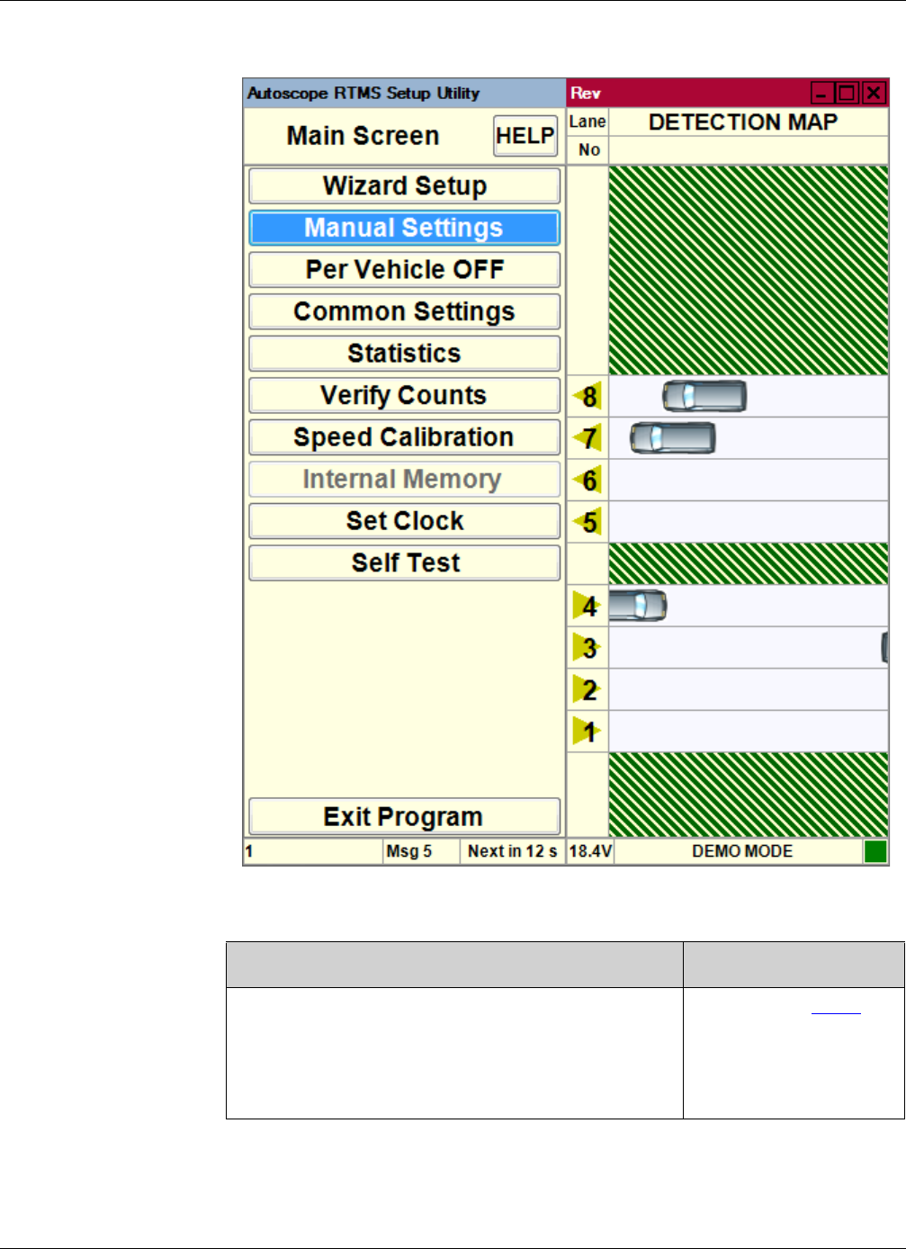
5. Do you see traffic in the Detection Map area?
6. On the Main Screen, click Manual Settings.
7. On the Manual Setup screen, click Data=.
Ye s No
You can now operate the software just as if you were
connected to an active Autoscope RTMS Sx-300
gathering data from live traffic. For information on
how to operate the software, see the sections that
follow in this manual.
Continue with Step 6
Chapter 3: Running Demo Mode
RTMS Sx-300 User Guide ©2014 Image Sensing Systems Inc. 3-14
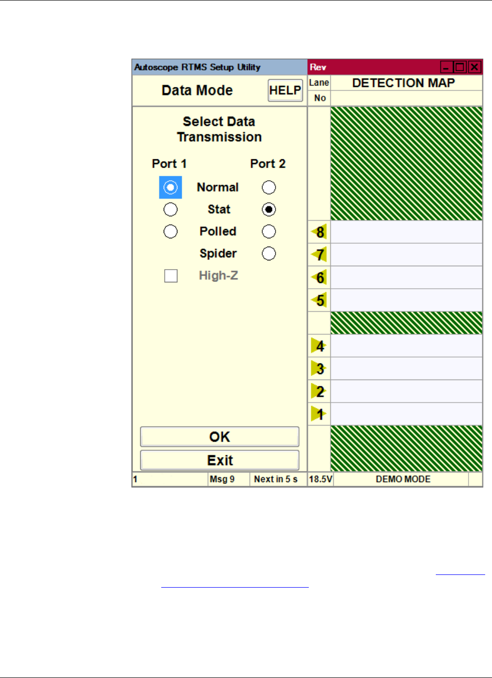
The following screen appears.
8. For Port 1, select Normal.
9. Click OK.
Traffic should appear in the Detection Map.
NOTE: If you want to change the message period from 60 seconds, see “Changing
the Message Period” on page 5-33.

Chapter 3: Setup Utility Screens
RTMS Sx-300 User Guide ©2014 Image Sensing Systems Inc. 3-15
Setup Utility Screens
The Setup Utility has numerous screens which provide for the various functions
supported by the utility. A list of the various screens and where information on each
can be found is provided in Table 3-1.
NOTE: There is a help file associated with each of the screens listed in the table.
Table 3-1: Location of Screen Descriptions
Screen Name Description Location
Advanced “Advanced Options” on page 5-1
Application “Step 1: Set the Application Mode” on page 4-2
Classification “Step 7: Define Vehicle Classifications” on page 4-23
Common Settings “Common Setup Options” on page 5-5
Communications “Defining Communications” on page 5-7
Data Mode “Changing the Data Mode” on page 5-2
File “Loading a Previously Saved Setup File” on page 5-22
“Recording Data To a File” on page 5-44
Fine Tune “Adjusting Zone Boundaries” on page 5-55
“Assigning Labels to Zones” on page 5-58
Firmware Upgrade “Upgrading Firmware” on page 5-49
Initial Setup (Wizard) “Step 2: Run the Wizard” on page 4-5
Internal Memory “Memory Operations” on page 5-25
Labelling “Assigning Labels to Zones” on page 5-58
Main “Main Screen” on page 3-19
Manual Setup “Manual Setup Screen” on page 3-21
Message Comp “Step 6: Define Message Composition” on page 4-20
Message Period “Changing the Message Period” on page 5-33
Self Test “Self Test” on page 5-45
Sensitivity “Sensitivity Adjustment” on page 5-47
Sensor ID “Setting the Sensor ID” on page 5-48
(Table continues on the next page)

Chapter 3: Setup Utility Screens
RTMS Sx-300 User Guide ©2014 Image Sensing Systems Inc. 3-16
Speed Calibration “Step 5: Calibrate Speed” on page 4-15
“Manual Speed Calibration” on page 5-24
Start “Start Screen” on page 3-17
Statistics “Viewing Statistics” on page 5-51
Verify Counts “Step 4: Verify Vehicle Counts” on page 4-10
Zone Setup “Step 3: Adjust the Zones” on page 4-8
Table 3-1: Location of Screen Descriptions (Cont’d)
Screen Name Description Location
Chapter 3: Start Screen
RTMS Sx-300 User Guide ©2014 Image Sensing Systems Inc. 3-17
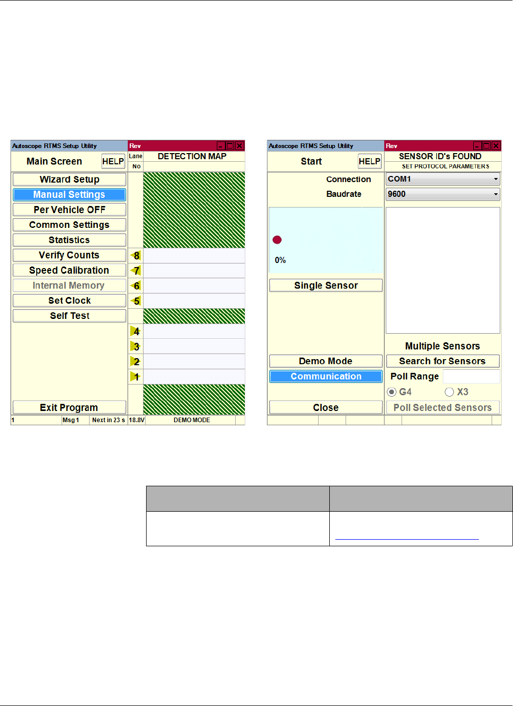
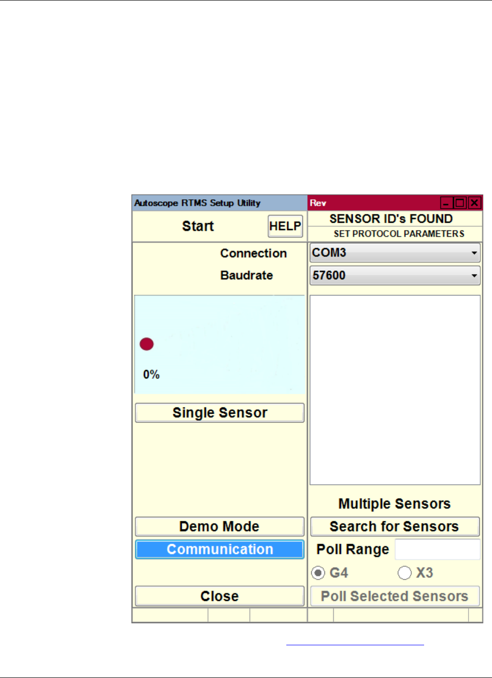
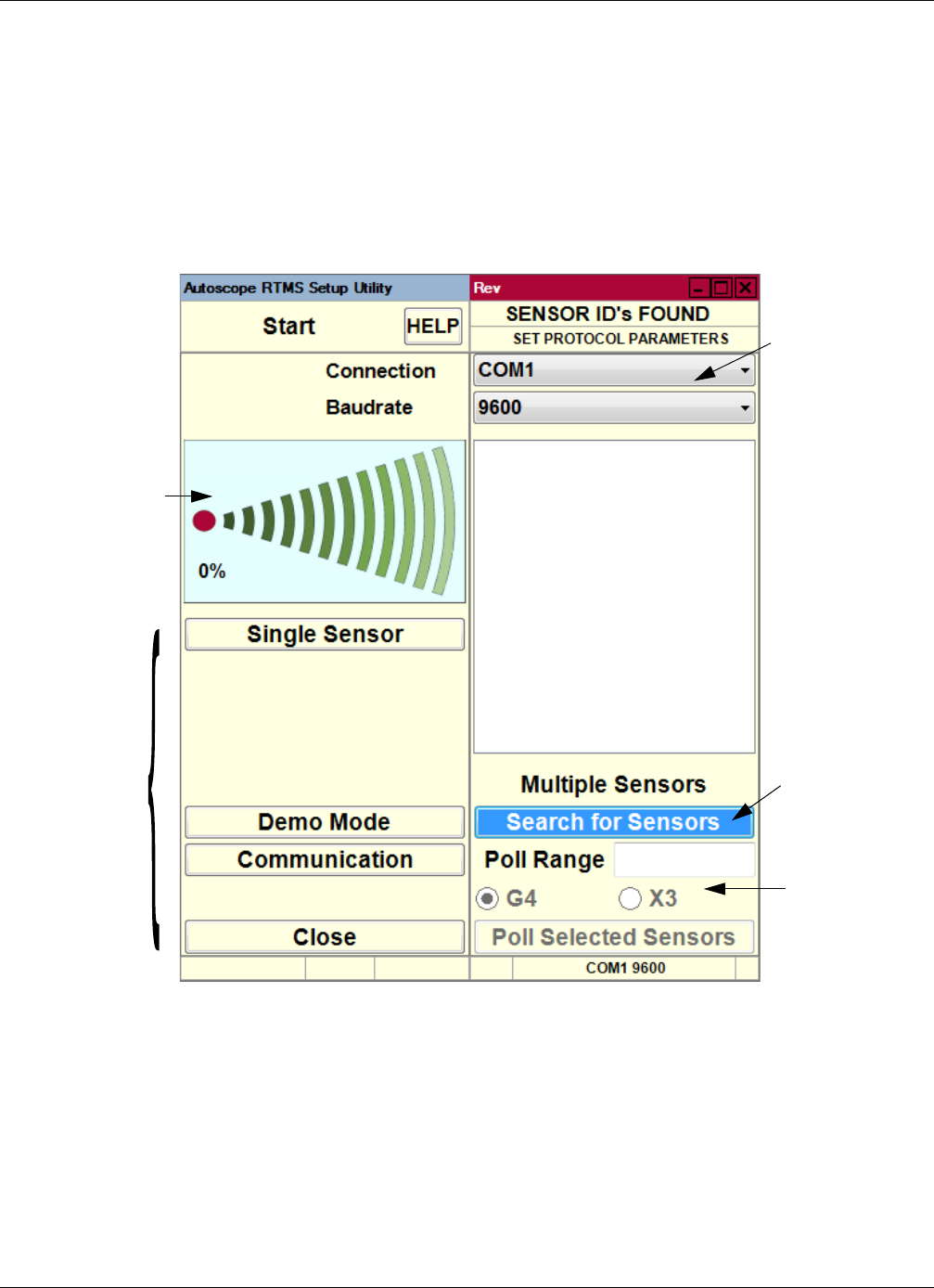
Start Screen
The Start screen is most often used to run Demo Mode and to test sensors in a polled
mode. This screen only appears during the start up of the Setup Utility when:
•You press the ESC key.
•No sensors are found.
•The detected Autoscope RTMS Sx-300 sensor is in Polled mode.
.
Figure 3-1: Start Screen
The following provides a brief description of each of the function buttons.
•Help — Opens a help page for this screen.
•Single RTMS — This option is used to connect to a single Autoscope RTMS
Sx-300 selected from the list in the right pane generated from a Search for
Sensors operation. The Main Screen will appear with the settings for that
Autoscope RTMS Sx-300.
Search progress
Menu buttons
Current
communications
options
Poll options
Search button

Chapter 3: Start Screen
RTMS Sx-300 User Guide ©2014 Image Sensing Systems Inc. 3-18
•Demo Mode — This option is used to run Demo Mode. For more
information, see “Running Demo Mode” on page 3-10.
•Communication — This option allows you to specify the connection method
between the Autoscope RTMS Sx-300 and your computer. For more
information see “Defining Communications” on page 5-7.
•Close — Used to exit the Setup Utility.
•Search for Sensors — This option is used to search for Autoscope RTMS
Sx-300 units. For more information, see “Finding Sensors” on page 5-19.
•Poll Selected Sensors — This option is used to poll the selected units. For
more information, see “Polling Sensors” on page 5-41.
Chapter 3: Main Screen
RTMS Sx-300 User Guide ©2014 Image Sensing Systems Inc. 3-19
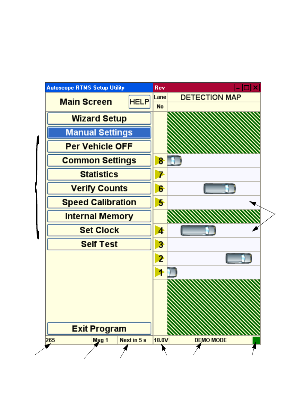
Main Screen
The Main Screen is vertically divided into two separate panels. The left panel consists
of function buttons. The right panel displays the detection map with the current
detection zones and the real-time detections indicated by moving vehicles. The title
bar runs horizontally across the top of the screen. The status bar runs horizontally
across the bottom.
Figure 3-2: Setup Utility Main Screen
Menu
buttons
Serial # and
firmware version
Message # Time to next
message
Traffic
info
Voltage
at unit
COM port
and speed
COM indicator

Chapter 3: Main Screen
RTMS Sx-300 User Guide ©2014 Image Sensing Systems Inc. 3-20
The following provides a brief description of each of the function buttons.
•Help — Opens a help page for this screen.
•Wizard Setup — This option is an automated Zone setup process. It scans the
range of the Autoscope RTMS Sx-300 microwave beam and automatically
configures up to 12 zones. For more information, see “Step 2: Run the
Wizard” on page 4-5.
•Manual Settings — This option displays a screen that allows you to
configure the Autoscope RTMS Sx-300. For more information, see “Manual
Setup Screen” on page 3-21.
•Per Vehicle — When this option is turned ON, it adds the time stamp, lane
number, classification, speed, and dwell time of every vehicle in real-time
data output. For more information see “Defining Per Vehicle Messages” on
page 5-31.
NOTE: This added information can create a huge file in a short time if
recording data to a file or it can fill the internal memory of the
sensor.
•Common Settings — This option displays a screen that allows you to save
configuration settings from one Autoscope RTMS Sx-300 and load them into
other Autoscope RTMS Sx-300 units. For more information see “Common
Setup Options” on page 5-5.
•Statistics — This option displays a screen that allows you to monitor key data
on the user interface.For more information see “Viewing Statistics” on
page 5-51.
•Verify Counts — This option displays a screen that allows you to compare
manual vehicle counts with Autoscope RTMS Sx-300 vehicle counts. For
more information see “Step 4: Verify Vehicle Counts” on page 4-10.
•Speed Calibration — This option displays a screen that allows you to match
actual speeds with the Autoscope RTMS Sx-300 calculated speed. For more
information see:
–“Step 5: Calibrate Speed” on page 4-15
–“Manual Speed Calibration” on page 5-24
•Internal Memory — This option displays a screen that allows you to store
data inside the Autoscope RTMS Sx-300 unit. The data can then be
downloaded at a later time. For more information see “Downloading
Autoscope RTMS Sx-300 Memory” on page 5-27.
•Set Clock — This option is used to synchronize the Autoscope RTMS Sx-300
clock with the clock on your computer.
•Self Test — This option displays a screen that allows you to initiate an
internal diagnostic test of the Autoscope RTMS Sx-300. For more information
see “Self Test” on page 5-45.
•Exit Program — This option closes the Setup Utility.
Chapter 3: Manual Setup Screen
RTMS Sx-300 User Guide ©2014 Image Sensing Systems Inc. 3-21
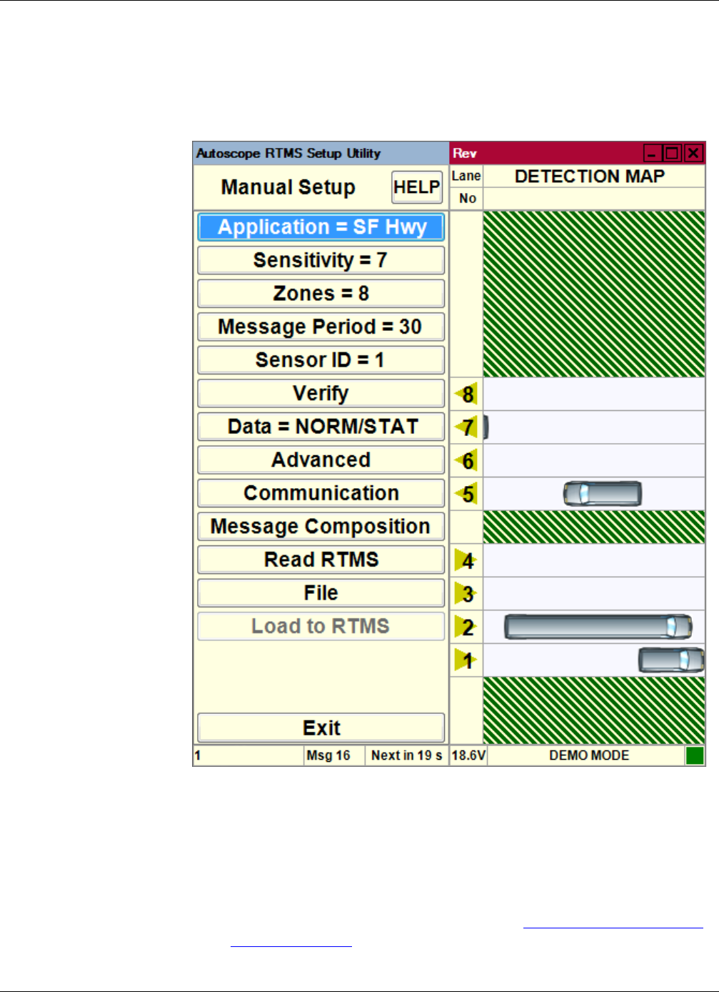
Manual Setup Screen
This screen displays options that allow you to manually configure the Autoscope
RTMS Sx-300.
Figure 3-3: Manual setup Screen
The options on this screen are:
•Help — Opens a help page for this screen.
•Application — This option displays a list of different sensing modes such as
side-fired and midblock. Select the mode that best matches your hardware
configuration and detection requirements. See “Step 1: Set the Application
Mode” on page 4-2.

Chapter 3: Manual Setup Screen
RTMS Sx-300 User Guide ©2014 Image Sensing Systems Inc. 3-22
•Sensitivity — This option displays sensitivity adjustment parameters used to
calibrate the sensitivity for a variety of vehicle sizes and sensing applications.
For more information see “Sensitivity Adjustment” on page 5-47.
•Zones — This option allows you to alter lane numbers, labeling, and to
manually adjust zone position and width. For more information see the
following:
–“Step 3: Adjust the Zones” on page 4-8
–“Zone Setup” on page 5-52
–“Assigning Labels to Zones” on page 5-58
•Message Period — This option allows you to configure the message period
for which statistical reports are generated. For more information see
“Changing the Message Period” on page 5-33.
•Sensor ID — This option allows you to set the Sensor ID parameter. For more
information see “Setting the Sensor ID” on page 5-48.
•Ver ify — This option allows you to manually verify traffic count results and
determine the percentage error. For more information see “Step 4: Veri fy
Vehicle Counts” on page 4-10.
•Data — This option allows you to control the basic data mode for a single
Autoscope RTMS Sx-300 device. For more information see “Changing the
Data Mode” on page 5-2.
•Advanced — This option accesses advanced features such as vehicle
classification options, Contact Closure configuration (if available) and
firmware upgrade management. For more information see “Advanced
Options” on page 5-1.
•Communication — This option allows you to specify the connection method
between the Autoscope RTMS Sx-300 and your computer. For more
information see “Defining Communications” on page 5-7.
•Message Composition — This option allows you to configure the content
and format of each statistical message. For more information see “Step 6:
Define Message Composition” on page 4-20.
•Read RTMS — This option transfers the current setup parameters from the
Autoscope RTMS Sx-300 to the software. For more information see
“Updating the Setup Utility With a New Configuration” on page 5-49.
•File — This option allows you to save and load configuration files as well as
record traffic statistical information. For more information see “Loading a
Previously Saved Setup File” on page 5-22.
•Load To RTMS — Clicking this button loads the current configuration
running in the Setup Utility to the Autoscope RTMS Sx-300. Note, this option
is not available in Demo mode. For more information see the following:
– “Loading a Previously Saved Setup File” on page 5-22
–“Recording Data To a File” on page 5-44
•Exit — Returns to the Main Screen.

Chapter 3: Default Settings
RTMS Sx-300 User Guide ©2014 Image Sensing Systems Inc. 3-23
Default Settings
The following table lists all of the default settings that are in place when you first start
up the Autoscope RTMS Setup Utility for an unconfigured sensor.
Table 3-2: Default Settings
Option Default Setting
Application Side-Fired Highway
For information about changing the Application setting,
see “Step 1: Set the Application Mode” on page 4-2.
Communications •PC Serial selected
•Serial Port: COM1
•Baudrate: 9600
•RTS/CTS Handshake: not selected
•Timeout, ms: 500
For information about changing the Communications
setting, see “Defining Communications” on page 5-7.
Data Mode •Port 1: Normal
•Port 2: Stat
For information about changing the Data Mode, see
“Changing the Data Mode” on page 5-2.
Internal Memory •Store Into Memory not selected
•FIFO not selected
For information about changing the Internal Memory
settings, see “Defining Memory Options” on page 5-25.
Lane labeling None
For information about labeling lanes, see “Assigning
Labels to Zones” on page 5-58.
(Table continues on the next page)

Chapter 3: Default Settings
RTMS Sx-300 User Guide ©2014 Image Sensing Systems Inc. 3-24
Message Composition •G4 STAT selected
•Volume selected
•Occupancy selected
•High Resolution selected
•6 Foot Loop Emulation selected
•Speed: Km/h
•Classification: 6 Classes
•Gap/Headway not selected
•85% Speed selected
•Real Time Clock selected
For information about changing the Message
Composition setting, see “Step 6: Define Message
Composition” on page 4-20.
Message Period 30 second
For information about changing the Message Period, see
“Changing the Message Period” on page 5-33.
Per Vehicle OFF
For more information see “Defining Per Vehicle
Messages” on page 5-31.
Sensitivity 7 or 8 (depends on the transceiver in the sensor)
For information about changing the Sensitivity setting,
see “Sensitivity Adjustment” on page 5-47.
Sensor ID 1
For information about changing the Sensor ID, see
“Setting the Sensor ID” on page 5-48.
Vehicle Classification
Lengths
Small
-------------------5
Regular
-------------------7
Medium
-------------------10
Large
-------------------15
Truck
-------------------20
XLRG
For information about changing the Vehicle
Classification Lengths, see “Step 7: Define Vehicle
Classifications” on page 4-23.
Zones Eight zones are selected.
Table 3-2: Default Settings (Cont’d)
Option Default Setting

RTMS Sx-300 User Guide ©2014 Image Sensing Systems Inc. 4-1
Chapter 4: Configuration and Setup
General
This chapter describes the procedures for configuring the Autoscope RTMS Sx-300
system using the Autoscope RTMS Setup Utility.
Configuration Process
After the Autoscope RTMS Sx-300 hardware and software are installed (see Chapters
2 and 3), you must set up and configure each of the Autoscope RTMS Sx-300 units in
the system.
The configuration process requires you to physically connect the computer where the
Autoscope RTMS Setup Utility is installed to each Autoscope RTMS Sx-300 in the
system. Once connected, you must start the Setup Utility (see “Starting the Setup
Utility” on page 3-7).
Each Autoscope RTMS Sx-300 must be set up (configured) according to the following
eight step process.
•Step 1:Set the Application Mode
•Step 2:Run the Wizard
•Step 3:Adjust the Zones
•Step 4:Verify Vehicle Counts
•Step 5:Calibrate Speed
•Step 6:Define Message Composition
•Step 7:Define Vehicle Classifications
•Step 8:Save the Configuration File
After the Configuration process is completed, you can adjust the Autoscope RTMS
Sx-300 setup as needed for your site. For more information see Chapter 5: “Operations
and Adjustments”.
Required Equipment/Personnel
The following equipment and personnel will be needed in order to perform the
configuration process.
•At least two persons
•A hand-held tally counter
•Light Detecting and Ranging (LIDAR) radar gun
•Speed calibration worksheet (see Appendix E: “Speed Calibration
Worksheet”)
•Stop watch
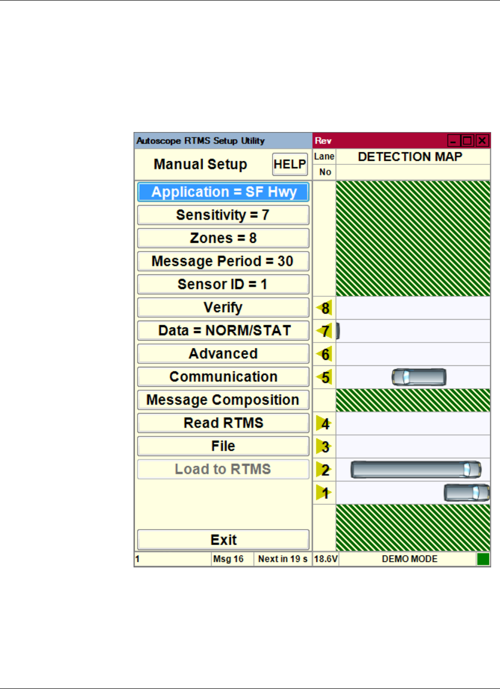
Chapter 4: Required Equipment/Personnel
RTMS Sx-300 User Guide ©2014 Image Sensing Systems Inc. 4-2
Step 1: Set the Application Mode
You must define whether the Autoscope RTMS Sx-300 is to operate in a Side-Fired or
Midblock application.
1. On the Main Screen, click Manual Settings.
The following screen appears.
2. Click Application =.
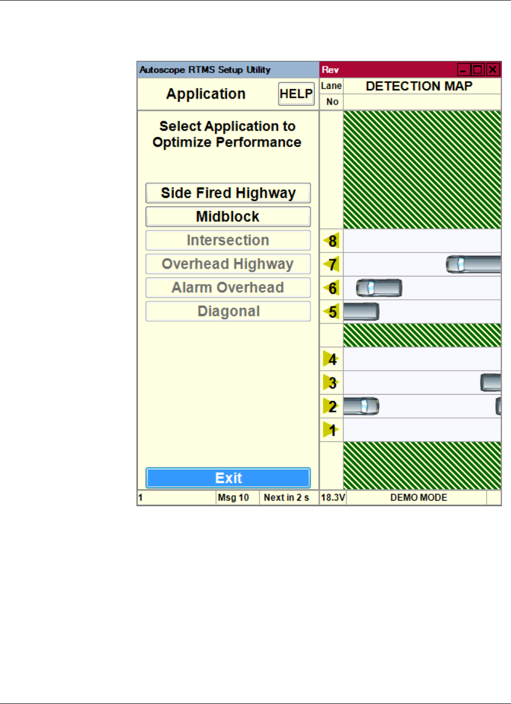
Chapter 4: Required Equipment/Personnel
RTMS Sx-300 User Guide ©2014 Image Sensing Systems Inc. 4-3
The following screen appears.
3. Select the application the Autoscope RTMS Sx-300 will be used for.
•Side Fired Highway — in general, used when:
– traffic is mainly free-flowing
– farther detection distance needed
– lanes are wide
•Midblock — in general, used when:
– traffic is mainly urban (can be congested)
– shorter detection distance needed
– lanes are narrow

Chapter 4: Required Equipment/Personnel
RTMS Sx-300 User Guide ©2014 Image Sensing Systems Inc. 4-4
NOTES:
•Click on the application to be used even if it already appears to be selected.
This will ensure that all settings are sent to the Autoscope RTMS Sx-300.
•If you get a message indicating that the application requires a new wizard
setup, click Yes.
4. To return to the Main Screen, click Exit.
5. Continue with “Step 2: Run the Wizard” on page 4-5.
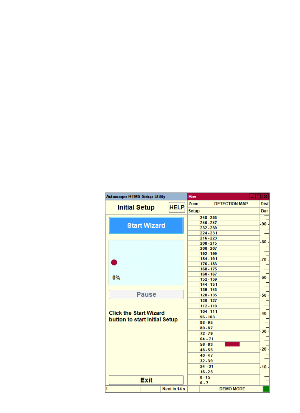
Chapter 4: Required Equipment/Personnel
RTMS Sx-300 User Guide ©2014 Image Sensing Systems Inc. 4-5
Step 2: Run the Wizard
The automated zone setup process requires free flowing traffic in all lanes of interest.
It scans the range of the Autoscope RTMS Sx-300 microwave beam and positions up
to 12 detection zones, representing lanes where vehicles are detected.
The Autoscope RTMS Setup Utility automatically detects traffic in its detection area
and configures lane parameters accordingly. This is a two-stage process.
•Initial setup: The Wizard finds zones which match up to the lanes of traffic.
•Final setup: The Wizard fine tunes the zone boundaries and detection
parameters.
NOTE: You may receive warnings while detecting traffic in low-volume lanes. The
warning asks if you would like to continue detection for one additional
minute. If the sensor is installed where it detects both mainline and secondary
zones such as ramps or frontage roads, these potentially low-volume zones
can be ignored if desired. Extending the wizard setup for the benefit of the
secondary zones is not necessary.
1. On the Main Screen, click Wizard Setup.
The following screen appears.
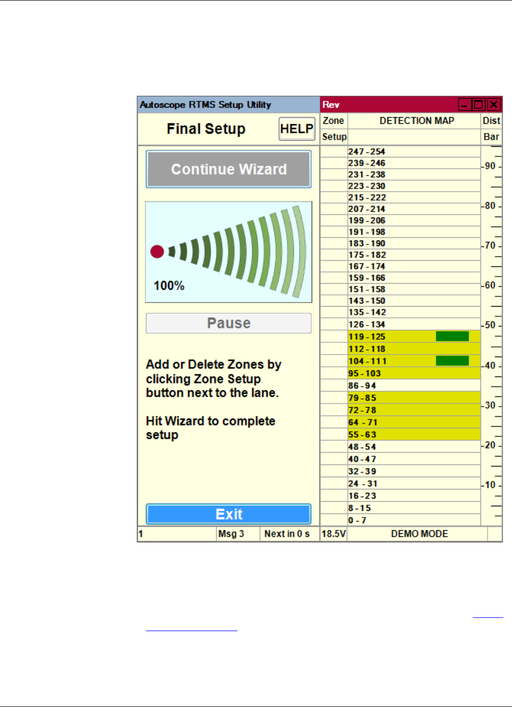
Chapter 4: Required Equipment/Personnel
RTMS Sx-300 User Guide ©2014 Image Sensing Systems Inc. 4-6
2. Click Start Wizard.
When the progress indicator reaches 100% the Wizard initial setup is complete.
The resulting zone setup is presented for approval.
3. Using the detection blips, confirm visually that the proposed location of lanes
corresponds to the zones you wish to include in the setup.
4. Add or delete zones until the desired position and quantity of zones is achieved.
Note, zones can be added or deleted by using the Fine Tune process (see “Zone
Setup” on page 5-52).
5. To complete the setup, click Continue Wizard.
The Wizard will begin and automatically run the Final Setup process.
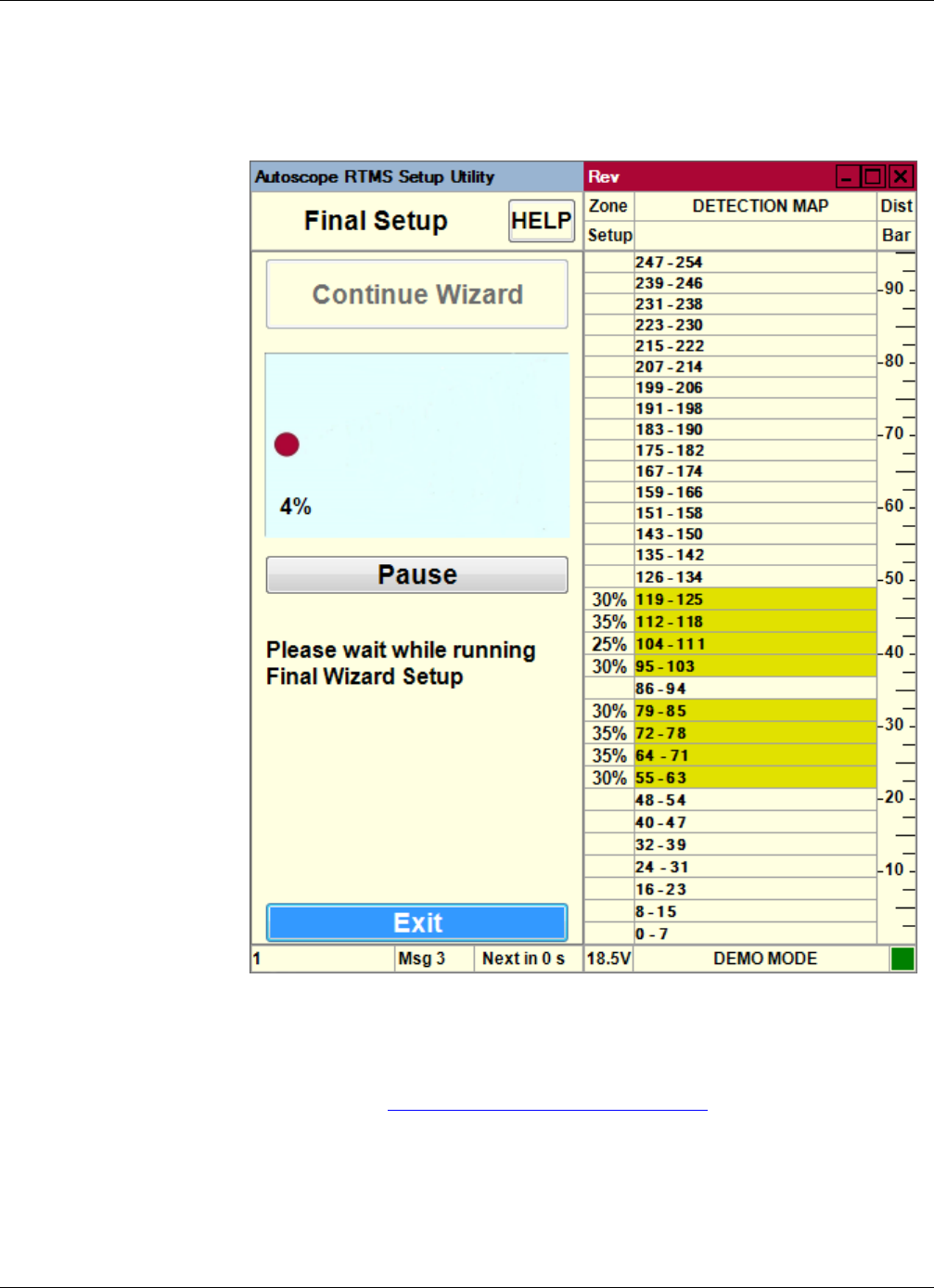
Chapter 4: Required Equipment/Personnel
RTMS Sx-300 User Guide ©2014 Image Sensing Systems Inc. 4-7
If traffic slows down momentarily or there is a large gap in the traffic flow, click
Pause. Pausing during moments of non-free-flow traffic will help the Wizard
extend it’s calibration time and ensure better calibration accuracy.
6. On completion, the Autoscope RTMS Setup Utility will return to the Main Screen.
Note, allow the Wizard to complete and return to the Main Screen, clicking
Cancel will interrupt the Final Setup process.
7. Continue with “Step 3: Adjust the Zones” on page 4-8.
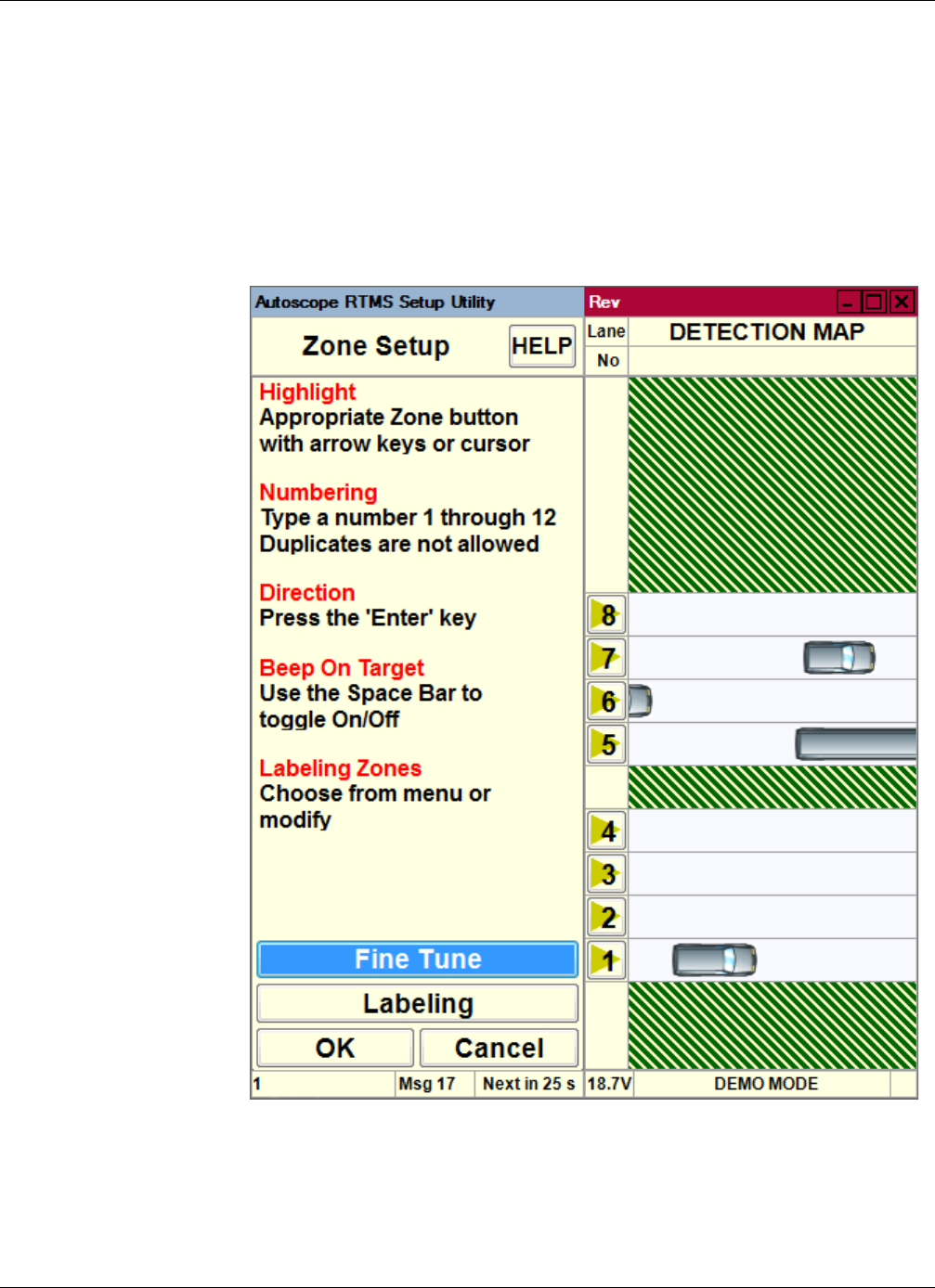
Chapter 4: Required Equipment/Personnel
RTMS Sx-300 User Guide ©2014 Image Sensing Systems Inc. 4-8
Step 3: Adjust the Zones
A zone that is created by the Autoscope RTMS Sx-300 ideally represents a detected
lane of traffic.
1. On the Main Screen, click Manual Settings.
2. On the Manual Setup screen, click Zones =.
The following screen appears.
3. Is traffic being shown travelling in the correct direction for each zone.?

Chapter 4: Required Equipment/Personnel
RTMS Sx-300 User Guide ©2014 Image Sensing Systems Inc. 4-9
4. For each zone monitor the vehicle icons on the detection map and compare them
with what you are physically seeing on the road.
5. Do the vehicle icons on the screen match what you are physically seeing on the
road?
6. Is the utility detecting more or fewer vehicles than what you are actually seeing on
the road?
7. Repeat Steps 4 – 6 of this procedure for each zone.
8. Do you want to add labels to the zones?
NOTE: Zone numbering must start at 1 and use sequential numbering.
The placement of the numbers can be in any order; however, it is
recommended that the nearest lane to Autoscope RTMS Sx-300 be
designated as 1, and the other lanes numbered in sequential order going away
from the Autoscope RTMS Sx-300.
9. Click OK to save your settings and return to the Manual Setup screen.
10. To return to the Main Screen, click Exit.
11. Continue with “Step 4: Verify Vehicle Counts” on page 4-10.
IMPORTANT: DO NOT proceed to Verifying Vehicle Counts until you are
confident that the physical vehicle detections match the detections
of the software.
Yes No
Continue with Step 4. a) Click on the zone number.
b) To change the direction, press Enter.
c) Continue with Step 4.
Yes No
Proceed to Step 8. The situation must be fixed. Continue with Step 6.
More Fewer
Fine tune the zones. See “Zone Setup”
on page 5-52
Adjust the sensitivity. See “Sensitivity
Adjustment” on page 5-47.
Ye s No
See “Assigning Labels to Zones” on page 5-58.
After all labels have been added, continue with
Step 9.
Continue with Step 9.
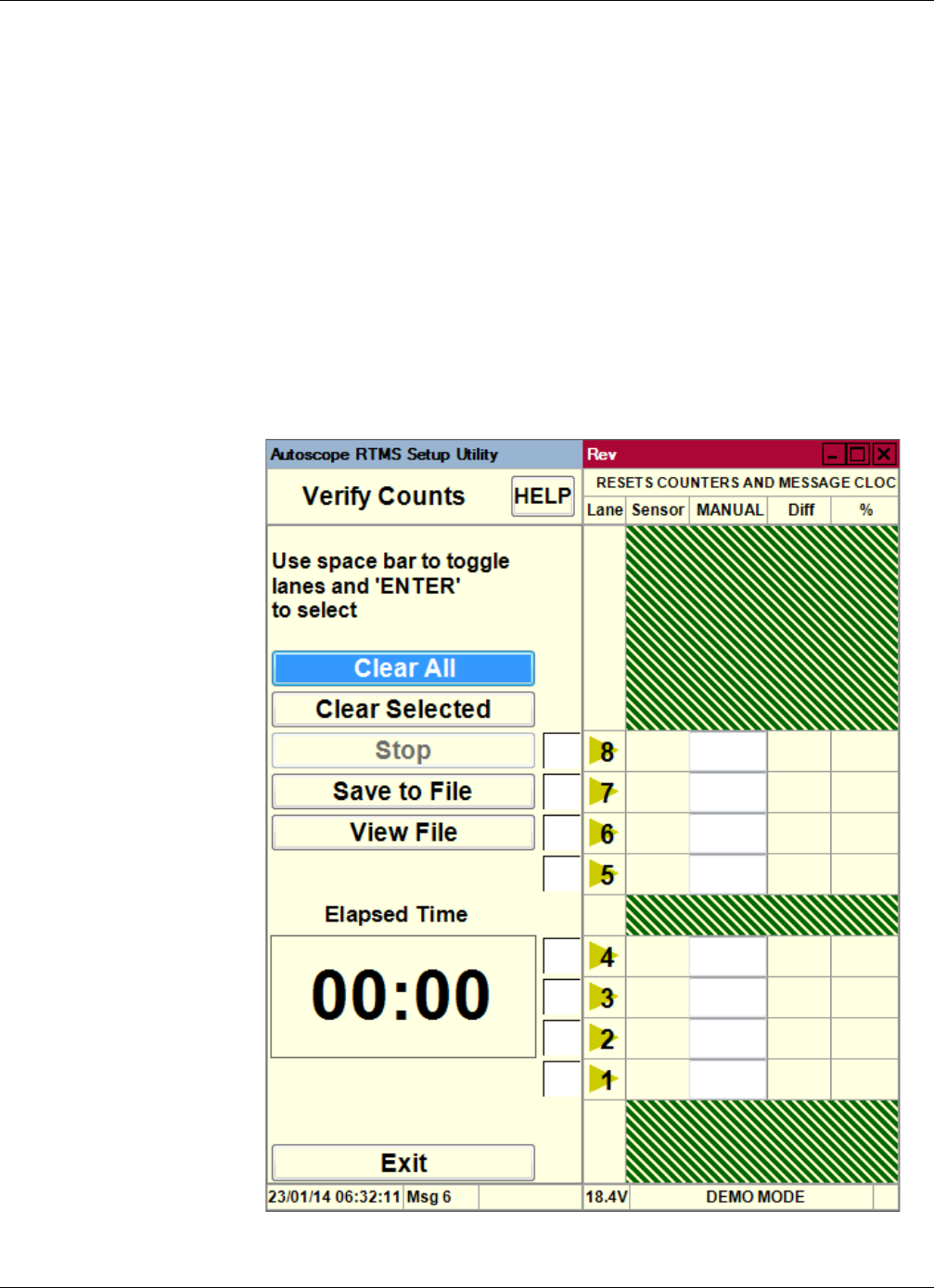
Chapter 4: Required Equipment/Personnel
RTMS Sx-300 User Guide ©2014 Image Sensing Systems Inc. 4-10
Step 4: Verify Vehicle Counts
The vehicle count verification of a successful zone setup is an essential part of the
installation. During the process you will compare Autoscope RTMS Sx-300 volume
counts over a period of time to a manual (visual) count for the same interval. Use of a
hand-held tally counter is recommended.
IMPORTANT: The recommended and most accurate method of verifying vehicle
counts is to perform the verification individually on each zone.
However, if a sufficient number of personnel are available, all zones
can be verified simultaneously. This alternate process requires at
least one person per zone for manual count purposes.
1. On the Main Screen, click Verify Counts.
The following screen appears.

Chapter 4: Required Equipment/Personnel
RTMS Sx-300 User Guide ©2014 Image Sensing Systems Inc. 4-11
2. Are you verifying counts for a single zone or for all zones?
The elapsed time counter starts automatically, and the count for each selected zone
is updated as vehicles pass.
3. Continue counting until a minimum of 50 vehicles (more than 50 is
recommended) have been counted for the zone being verified. This will usually
take several minutes.
4. Click Stop when there is a gap in the traffic and immediately stop your manual
counting.
5. Select the box in the Manual column and enter the manual count for the zone.
Single Zone All Zones
a) Select the check box to the left of
each zone.
b) Click Clear Selected and
immediately begin counting
vehicles as they cross the
Autoscope RTMS Sx-300 beam.
NOTE: There must be one person
per zone.
Click Clear All and immediately
begin counting vehicles as they cross
the Autoscope RTMS Sx-300 beam.
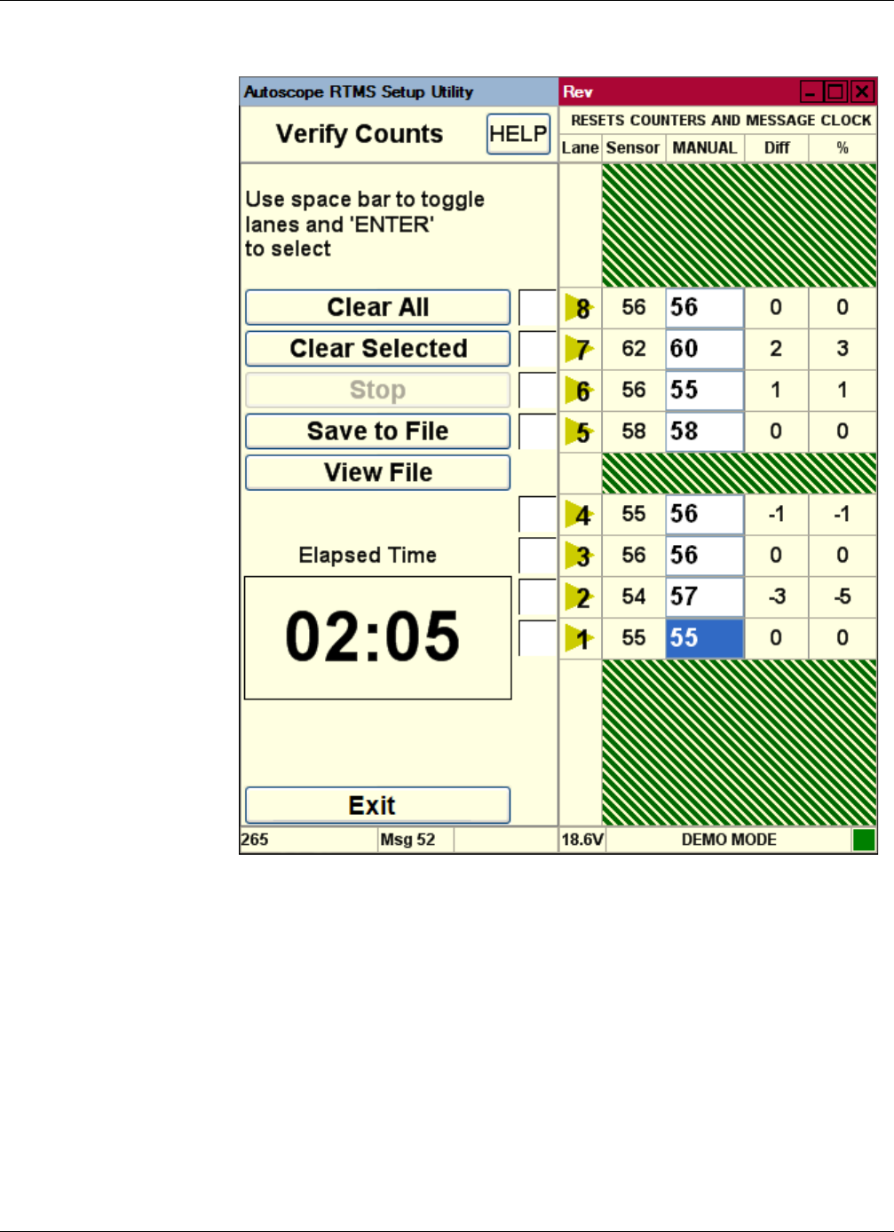
Chapter 4: Required Equipment/Personnel
RTMS Sx-300 User Guide ©2014 Image Sensing Systems Inc. 4-12
The difference between the Autoscope RTMS Sx-300 and the manual counts in
difference and percentage deviation is immediately displayed. Deviation of more
than 5% requires zone setup correction to improve detection accuracy.
If the Autoscope RTMS Sx-300 count is greater than 5% of the manual count, this
could be caused by:
– Splashing” (vehicles in one zone are shown as being detected in an
adjacent zone)
– Lane changing
– Reflections from fixed objects
– Sensitivity set too high
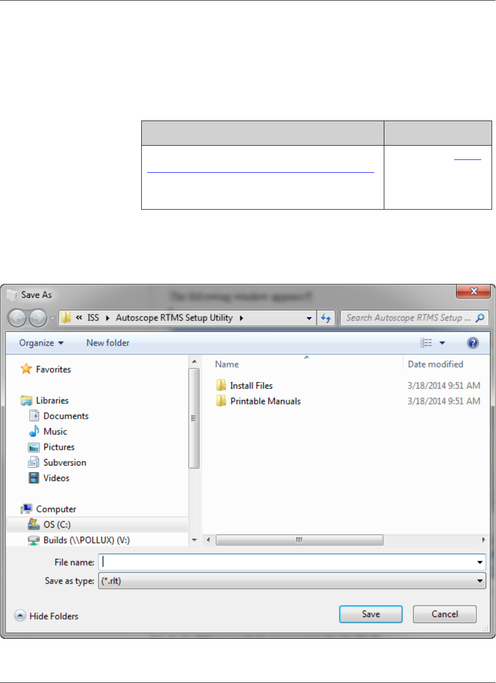
Chapter 4: Required Equipment/Personnel
RTMS Sx-300 User Guide ©2014 Image Sensing Systems Inc. 4-13
If the Autoscope RTMS Sx-300 count is less than 5% of the manual count
(negative percentage), this could be caused by:
– Missed small vehicles (sensitivity is too low)
– Occlusions
– Incorrect aiming
6. Are any of the percentages over five percent (either plus or minus)?
7. (Optional) If you want save the accumulated results of verification in a text file,
click Save to File.
The following window appears.
Yes No
You should make corrections before continuing. See
“Optimizing Volume Count Accuracy” on page 5-34.
After adjustments have been made, repeat the
verification process.
Continue with Step 7.

Chapter 4: Required Equipment/Personnel
RTMS Sx-300 User Guide ©2014 Image Sensing Systems Inc. 4-14
8. In the Save in field, select the folder where the file is to be saved.
The default location, Autoscope RTMS Setup Utility, is recommended.
9. In the File name field, type a name for the file.
10. Click Save.
11. To return to the Main Screen, click Exit.
12. Continue with “Step 5: Calibrate Speed” on page 4-15.

Chapter 4: Required Equipment/Personnel
RTMS Sx-300 User Guide ©2014 Image Sensing Systems Inc. 4-15
Step 5: Calibrate Speed
Speed calibration is a three step process that requires the following to be performed:
•Setting up the reference speed
•Running the automatic calibration
•Checking the calibration
In order to perform the speed calibration process, the following is required:
•Light Detecting and Ranging (LIDAR) radar gun or a similar device
•Speed calibration worksheet (see Appendix E: “Speed Calibration
Worksheet” or the online version in the Autoscope RTMS Sx-300 help files).
•Two people
NOTES:
•Prior to performing any speed calibration on the Autoscope RTMS Sx-300,
ensure that the volume accuracy has been optimized. This will enable the
speed calibration to proceed smoothly and provide quality results.
•Speed calibration should be performed when traffic is moving at the posted
speed limit, do not perform any calibration during periods of fluctuation or
congestion.
Step 5A: Setting the Reference Speed
The reference speed is the average speed that most vehicles travel through a zone.
1. On the Main Screen, click Manual Settings.
2. On the Manual Setup screen, click Message Period.
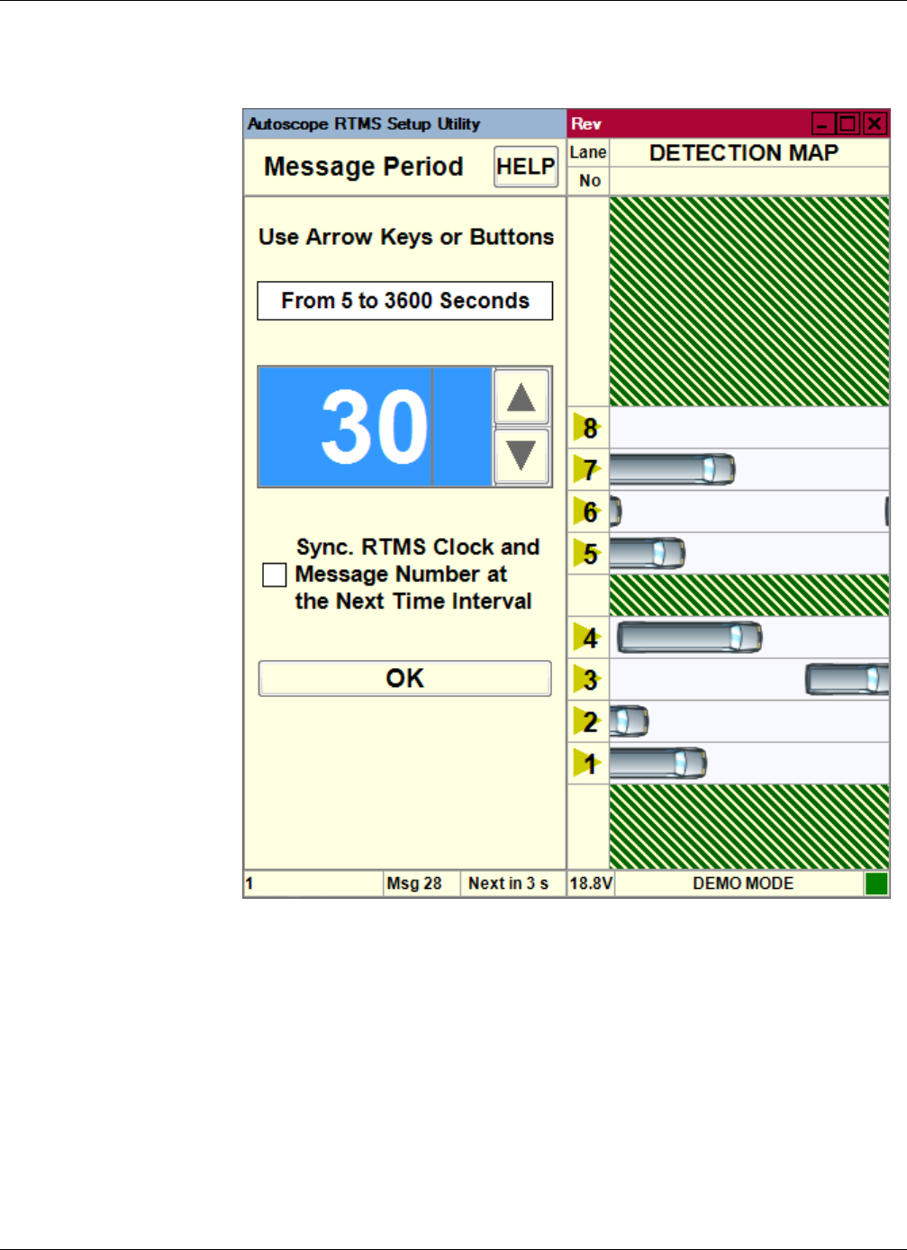
Chapter 4: Required Equipment/Personnel
RTMS Sx-300 User Guide ©2014 Image Sensing Systems Inc. 4-16
The following screen appears.
3. Verify that the message period is 30 seconds. If not, use the up/down arrows to set
it to 30.
NOTE: During automatic speed calibration the message period is temporarily
changed to 30 seconds and will sync with the countdown timer. When the
timer completes, the message period will return to the original value.
4. Click OK to return to the Manual Settings screen.
5. Click Exit to return to the Main Screen.
6. On the Main Screen, click Speed Calibration.
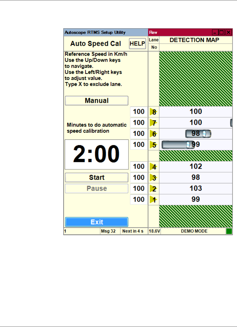
Chapter 4: Required Equipment/Personnel
RTMS Sx-300 User Guide ©2014 Image Sensing Systems Inc. 4-17
The following screen appears.
7. Verify the following:
•All zones are correctly shown.
•Auto Speed Cal is displayed at the top of the screen.
8. Using the radar gun, check the speed of 5 random vehicles in a single lane.
9. On the Autoscope RTMS Sx-300 Speed Calibration Worksheet, record the speeds
in the rows labeled LIDAR - A.
10. Calculate the average of the 5 speeds and record the value in the Ref Speed =
block of the worksheet.

Chapter 4: Required Equipment/Personnel
RTMS Sx-300 User Guide ©2014 Image Sensing Systems Inc. 4-18
11. On the Speed Calibration screen, enter the value to the left of the lane number.
12. Repeat Steps 8 – 11 for each lane at the site.
13. Continue with “Step 5B: Auto Calibration”.
Step 5B: Auto Calibration
In this step you will try to match the Autoscope RTMS Sx-300 calculated speed of
vehicles with actual speed.
1. On the Speed Calibration screen, set the run time to 5 minutes.
a) Click in the time field.
b) Use the Right and Left Arrow keys on the keyboard to increase or decrease
the value.
NOTE: Depending on traffic volumes the calibration time may need to be extended.
If volumes are less than 5-6 vehicles per lane per minute the time should be
extended as necessary to obtain at least 25-30 samples per lane during the
auto calibration.
2. Click Start.
Statistical speed values are displayed in each of the lanes in the detection map.
Note, do not stop the process until the 5 minutes has run out.
3. After the time period elapses, continue with “Step 5C: Check Calibration”.
Step 5C: Check Calibration
This step must be performed on each lane at the site, and requires a two-person team
and a stop watch.
NOTE: The Autoscope RTMS Sx-300 utility should be setup to record the 30-second
message periods. This procedure must be started at the beginning of a new
message period, Next in at the bottom of the screen shows 30.
Person 1 is responsible for monitoring the time and recording the information called
out by person 2 on the Speed Calibration Worksheet (see Appendix E: “Speed
Calibration Worksheet”).
Person 2 is responsible for using the radar gun to check the speeds of vehicles in the
zone being monitored and calling out the recorded speeds to person 1.
1. Person 1: At the beginning of a message period, instruct person 2 to start
gathering individual speed readings.
Person 2: When told to start, use the radar gun to check the speed of passing
vehicles in one lane. Call out the speed of each vehicle to person 1.
2. Person 1: Record the speeds in the four rows labeled LIDAR - B on the
worksheet as reported by person 2.
The number of vehicles recorded is dependent on how many (40 or less) are
checked during the five minute period.

Chapter 4: Required Equipment/Personnel
RTMS Sx-300 User Guide ©2014 Image Sensing Systems Inc. 4-19
3. Persons 1 and 2: Continue monitoring and recording for a total of 5 minutes (10
message periods).
4. When the 5 minute period is up:
•Person 1: Tell person 2 to stop monitoring. Calculate the average of the
recorded speeds and enter the value in the RTMS Sx-300 Avg = field on the
worksheet.
•Person 2: Stop monitoring and reporting.
5. Person 1: Calculate the average of the recorded speeds and enter the value in the
LIDAR Avg = field on the worksheet.
6. Person 1: Calculate the difference between the RTMS Sx-300 Avg and the
LIDAR Avg and enter the value in the Speed Difference (LIDAR - RTMS
Sx-300) field.
7. Person 1: Calculate the percentage difference and record the value in the%
Difference (LIDAR-Sx-300/LIDAR) field.
8. Is the percentage difference less than or more than ±10%?
9. To return to the Main Screen, click Back.
10. Continue with “Step 6: Define Message Composition” on page 4-20.
Less than More than
Calibration passes. Repeat the
procedure for each zone at the site.
Calibration fails. Manually calibrate
the zone (see “Manual Speed
Calibration” on page 5-24).
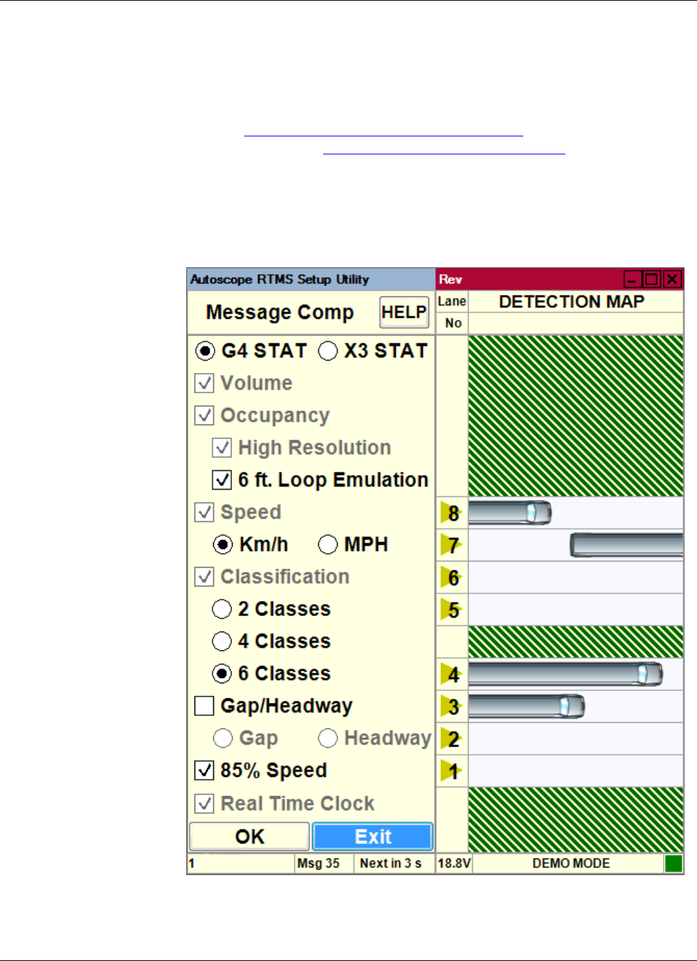
Chapter 4: Required Equipment/Personnel
RTMS Sx-300 User Guide ©2014 Image Sensing Systems Inc. 4-20
Step 6: Define Message Composition
The Message Composition defines the content and format of the statistical messages
that are sent from the Autoscope RTMS Sx-300 sensor to the connected hardware
(e.g., computer, smart phone, etc.). Messages are automatically sent every message
period (see “Changing the Message Period” on page 5-33) when the data mode is set
to STAT or Normal (see “Changing the Data Mode” on page 5-2).
1. On the Main Screen, click Manual Settings.
2. On the Manual Setup screen, click Message Composition.
The following screen appears.
3. Select options as appropriate for your site.

Chapter 4: Required Equipment/Personnel
RTMS Sx-300 User Guide ©2014 Image Sensing Systems Inc. 4-21
Some options are always selected, some are always selectable and some are not
available for X3 STAT protocol. For a description of each option, see Table 4-1
below.
Table 4-1: Message Composition Options
Option Description
G4 STAT Select this option if data is to be transmitted using the G4
protocol (message format).
Note, if you change from X3 STAT to G4 STAT, a message
appears indicating that the contents of memory will be erased.
X3 STAT Select this option if data is to be transmitted using the X3
protocol (legacy message format).
Note, if you change from G4 STAT to X3 STAT, a message
appears indicating that the contents of memory will be erased.
Volume This option is always selected and indicates that the total number
of vehicles detected in each message period will be included in
the statistical message.
Occupancy This option is always selected and indicates that the percentage
of time a lane is occupied by a vehicle during the message
period will be included in the statistical message.
High
Resolution
When selected, decimal places will be used for the Occupancy
results. For example, if this option selected, 87.7 = 87.7; if not
selected, 87.7 = 88.
For G4 STAT protocol, this option is always selected.
For X3 STAT protocol, this option is selectable.
6 ft Loop
Emulation
When selected, adds a virtual loop length of 6ft to the vehicle
length for occupancy calculations.
Speed This option is always selected and indicates that the average
vehicle speed during the message period will be included in the
statistical message in the selected measurement unit (Km/h or
MPH).
Km/h When selected, the average vehicle speed data will be in
kilometers per hour.
Note, in X3 STAT protocol, the data output is always in Km/h
units. The Autoscope RTMS Setup Utility will display in MPH,
but the output is always Km/h.
MPH When selected, the average vehicle speed data will be in miles
per hour.
(Table continues on the next page)

Chapter 4: Required Equipment/Personnel
RTMS Sx-300 User Guide ©2014 Image Sensing Systems Inc. 4-22
4. To save the options and return to the Manual Setup screen, click OK. Otherwise,
click Exit to return without saving.
5. Continue with “Step 7: Define Vehicle Classifications” on page 4-23.
Classification This option is always selected and indicates that the selected
number of vehicle classifications will be included in the
statistical message.
The number selected (2, 4 or 6) is what appears on the
Classification screen.
2 Classes When selected, classification data is for Small and Truck.
4 Classes When selected, classification data is for Small, Medium, Large
and Truck.
6 Classes When selected, classification data is for Small, Regular,
Medium, Large, Truck and Extra Large.
Gap/Headway When selected, the average time between vehicles by Gap or
Headway during a message period will be included in the
statistical message.
Gap When selected, the average time between the trailing edge of the
previous vehicle and leading edge of the current vehicle during a
message period will be included in the statistical message.
Headway When selected, the average time between the leading edge of the
previous vehicle and leading edge of the current vehicle during a
message period will be included in the statistical message.
Note, this option is not available for X3 STAT protocol.
85% Speed When selected, 85% of the vehicles are at or below this speed
during a message period will be included in the statistical
message.
Note, this option is not available for X3 STAT protocol.
Real Time
Clock
When selected, the Autoscope RTMS Sx-300 sends its time
stamp with each statistical message.
For G4 STAT protocol, this option is always selected.
For X3 STAT protocol, this option is always selected if Store
Into Memory is selected on the Internal Memory screen (see
“Defining Memory Options” on page 5-25). If Store Into
Memory is not selected, then the Real Time Option can be
unselected.
Table 4-1: Message Composition Options (Cont’d)
Option Description
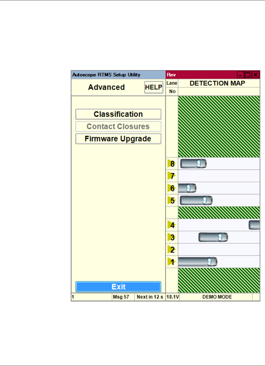
Chapter 4: Required Equipment/Personnel
RTMS Sx-300 User Guide ©2014 Image Sensing Systems Inc. 4-23
Step 7: Define Vehicle Classifications
The correct classification of vehicles by length requires accurately defined limits per
vehicle class.
1. On the Manual Setup screen, click Advanced.
The following screen appears.
2. Click Classification.
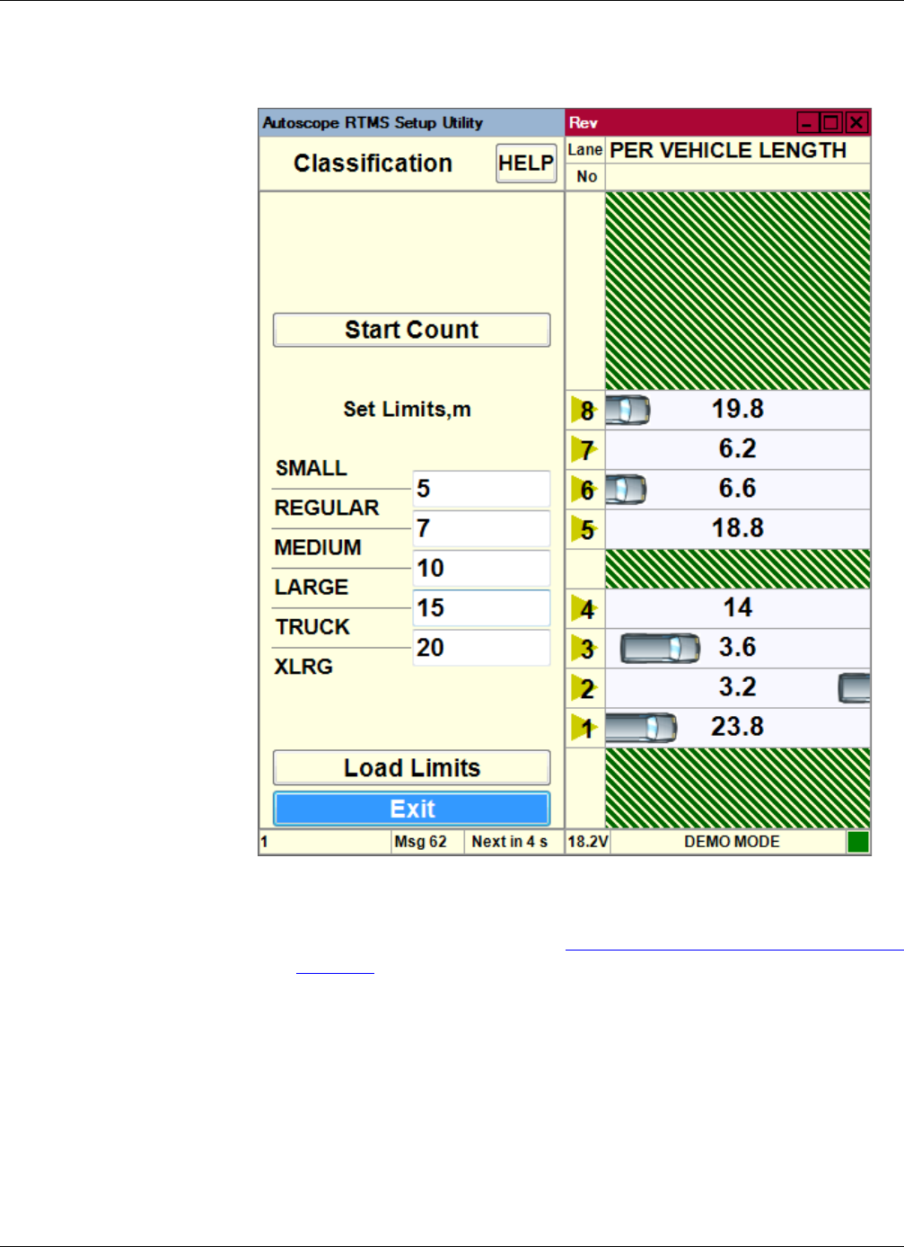
Chapter 4: Required Equipment/Personnel
RTMS Sx-300 User Guide ©2014 Image Sensing Systems Inc. 4-24
The following screen appears.
NOTE: The number of classifications shown and the length measurement unit
(meters or feet) are determined by the selections for Classification and Speed
on the Message Comp screen (see “Step 6: Define Message Composition” on
page 4-20).
3. To the right of each class enter the estimated size of the vehicle lengths.
The maximum length that can be specified is 25.5 m (83.6 ft)
The default size for each class is:
•Small: 0 – 5 meters (0 – 16.4 ft)
•Regular: 5 – 7 meters (16.4 – 22.9 ft)
•Medium: 7 – 10 meters (22.9 – 32.8 ft)
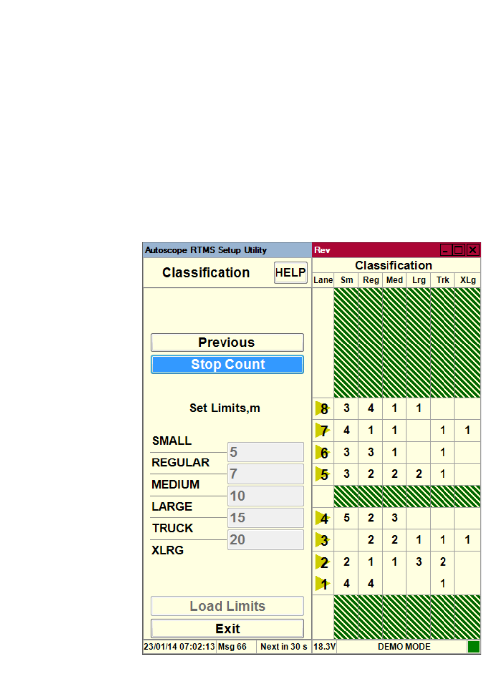
Chapter 4: Required Equipment/Personnel
RTMS Sx-300 User Guide ©2014 Image Sensing Systems Inc. 4-25
•Large: 10 – 15 meters (32.8 – 49.2 ft)
•Truck: 15 – 20 meters (49.2 – 65.6 ft)
•XLRG: greater than 20 meters (65.6 ft)
For best results, ensure that differences between length limits are greater than 3 m
(10 ft) especially for larger vehicles. Small separation values increase potential for
“merging” of classes (vehicle counting errors are the result).
4. Click Load Limits to send the defined length limits to the Autoscope RTMS
Sx-300.
5. Check the accuracy of the length limits by comparing the accumulated per vehicle
classification counts to manual counts for a period of at least two minutes.
6. Click Start Count.
The following screen appears.

Chapter 4: Required Equipment/Personnel
RTMS Sx-300 User Guide ©2014 Image Sensing Systems Inc. 4-26
7. Watch the actual traffic and compare what you see with the Autoscope RTMS
Sx-300 counts.
8. Click Stop Count.
9. Do the automated counts match what you’re seeing?
10. Click Back twice to return to the Manual Setup screen.
11. Continue with “Step 8: Save the Configuration File” on page 4-27.
Ye s No
Continue with Step 10. Repeat Steps 3 – 8.
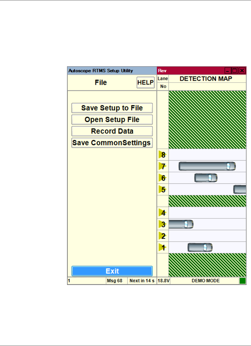
Chapter 4: Required Equipment/Personnel
RTMS Sx-300 User Guide ©2014 Image Sensing Systems Inc. 4-27
Step 8: Save the Configuration File
After you have completed the configuration you should save it to a file on your hard
drive for backup purposes.
1. On the Manual Setup screen, click File.
The following screen appears.
2. Click Save Setup to File.
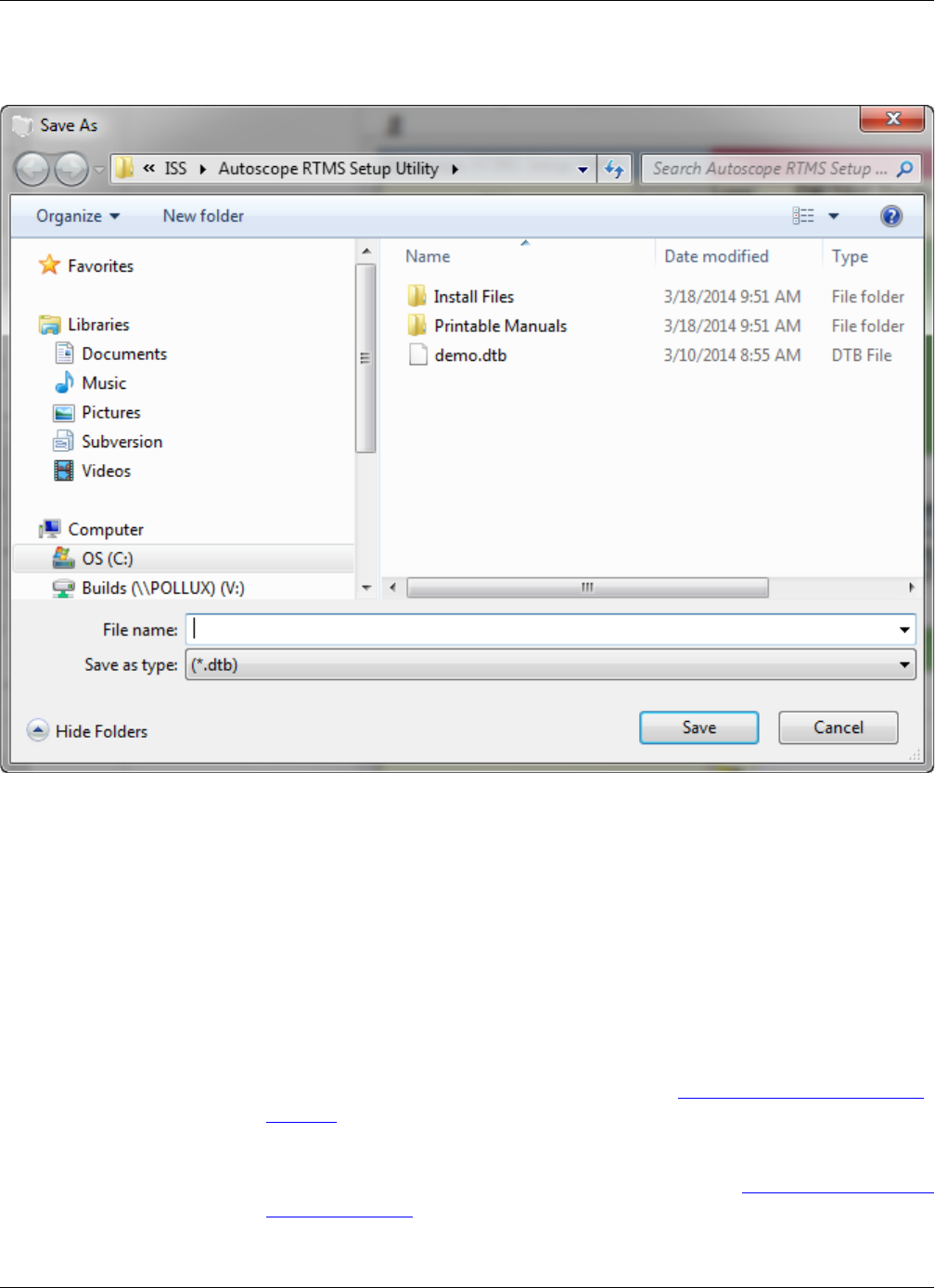
Chapter 4: Required Equipment/Personnel
RTMS Sx-300 User Guide ©2014 Image Sensing Systems Inc. 4-28
The following window appears.
3. In the Save in field, select the location where the file is to be saved.
4. In the File name field, enter a name for the file.
The following format is recommended: RTMS Sx-300xxx_date.dtb
where: xxx = location ID
date = date the file was created in YYYY_MM_DD format
dtb = file type (mandatory)
5. Click Save.
6. If you will be configuring several Autoscope RTMS Sx-300 sensors with the same
basic set up, click Save Common Settings.
For more information about common settings, see “Common Setup Options” on
page 5-5.
7. Click Back twice to return to the Main Screen.
8. Make adjustments and setup other options as required (see Chapter 5: “Operations
and Adjustments”).
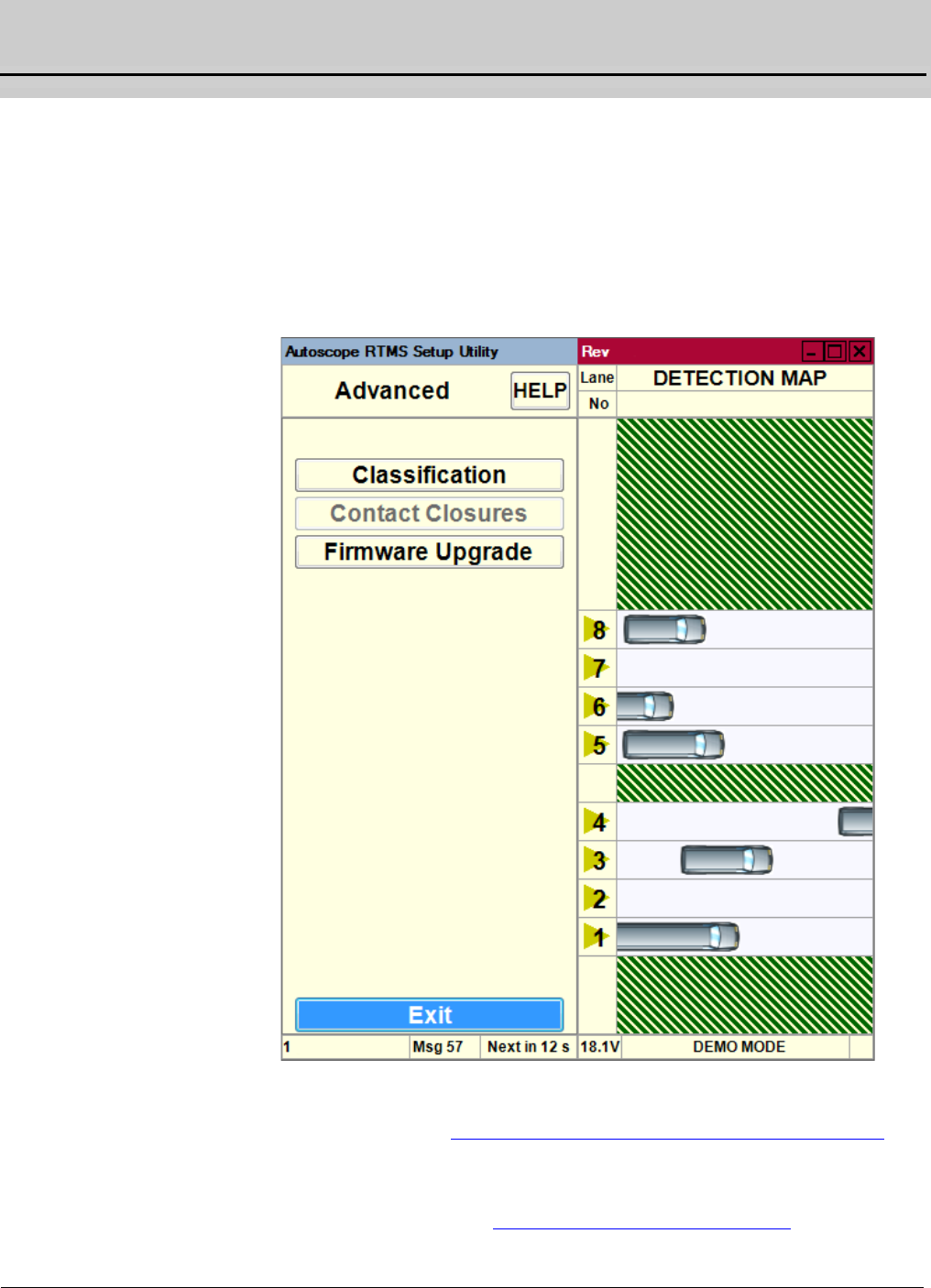
RTMS Sx-300 User Guide ©2014 Image Sensing Systems Inc. 5-1
Chapter 5: Operations and Adjustments
General
This chapter describes operations that can be performed and adjustments that can be
made after the Autoscope RTMS Sx-300 is installed and configured.
Advanced Options
The advanced options enable you to set the vehicle classifications and to upgrade the
firmware in the Autoscope RTMS Sx-300 sensor.
For information about these functions, see:
•For Classification: “Step 7: Define Vehicle Classifications” on page 4-23
•For Contact Closure: the Autoscope RTMS Sx-300 Optional Configurations
User Guide (PN A900-1155-2)
•For Firmware Upgrade: “Upgrading Firmware” on page 5-49

Chapter 5: Changing the Data Mode
RTMS Sx-300 User Guide ©2014 Image Sensing Systems Inc. 5-2
Changing the Data Mode
The Data Mode determines how the Autoscope RTMS Sx-300 sensor transmits
statistical messages, per vehicle data (if Per Vehicle is turned ON) and lane presence
information (used for vehicle animation).
The data mode is set per transmission port within the Autoscope RTMS Sx-300 sensor
as follows:
•Port 1 is a serial port used for communication with the Autoscope RTMS
Sx-300. Every Autoscope RTMS Sx-300 device has this communication port.
Port 1 is also shared with the bluetooth module for wireless communication
with Autoscope RTMS Sx-300.
•Port 2 is a communication channel used by optional equipment such as,
TCP/IP module or second serial port. For more information on these module
refer to the Autoscope RTMS Sx-300 Optional Configurations User Guide
(PN A900-1155-2).
1. Start the utility (see “Starting the Setup Utility” on page 3-7).
2. On the Main Screen, click Manual Settings.
3. On the Manual Setup screen, click Data=.
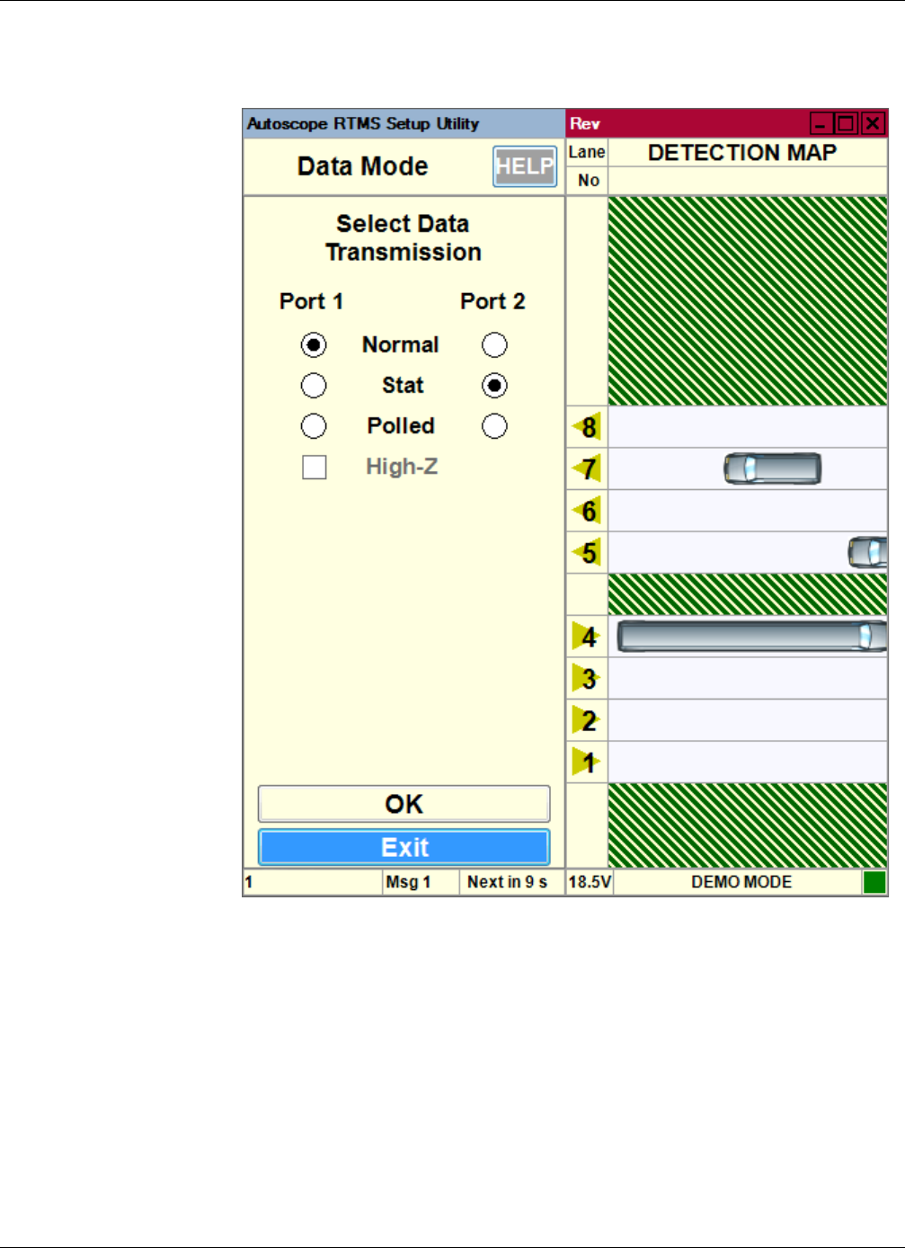
Chapter 5: Changing the Data Mode
RTMS Sx-300 User Guide ©2014 Image Sensing Systems Inc. 5-3
The following screen appears.
4. Select the appropriate options.
•Normal — Statistical messages are transmitted at the end of every message
period and all per vehicle information to display traffic lane presence
information such as vehicle icons, speeds etc.
•Stat — Statistical messages are only transmitted at the end of every message
period.
•Polled — Only statistical data that is currently stored in the Autoscope RTMS
Sx-300 buffer is transmitted and only when a matching sensor ID request is
received by the Autoscope RTMS Sx-300 sensor.

Chapter 5: Changing the Data Mode
RTMS Sx-300 User Guide ©2014 Image Sensing Systems Inc. 5-4
NOTE: If the Autoscope RTMS Sx-300 port over which the Autoscope RTMS Setup
Utility communicates to the sensor is set to polled, the data recording
functions on the Statistics and File screens are disabled. Also, there will not
be any per vehicle data available in the live data stream; however, the per
vehicle data is available from internal memory downloads if the Store Into
Memory option is enabled (see “Defining Memory Options” on page 5-25).
•High-Z — This option leaves the transmit pin in high-impedance mode. This
is only available in Polled mode when there are more than two sensors on the
same line.
5. To set the new value and return to the Manual Setup screen, click OK.

Chapter 5: Common Setup Options
RTMS Sx-300 User Guide ©2014 Image Sensing Systems Inc. 5-5
Common Setup Options
Setup Parameters are often common to all sensors on a single site. For example, the
sensors in a midblock deployment or string of detection stations along the same
highway. To save the installer time and effort in repeatedly entering the same
parameters in each site, a group of settings is defined as common settings. Common
settings allow you to specify the basic parameters for an entire group of sensors and to
load these settings into each Autoscope RTMS Sx-300 in the group.
The common setup options that can be selected are:
•Application (“Set the Application Mode” on page 4-2)
•Data (“Changing the Data Mode” on page 5-2)
•Message Period (“Changing the Message Period” on page 5-33)
•Classification (“Define Vehicle Classifications” on page 4-23)
•Message Comp. (“Define Message Composition” on page 4-20)
•Per vehicle On/Off (“Defining Per Vehicle Messages” on page 5-31)
•Lane #s & Labeling (“Zone Setup” on page 5-52)
In order to establish and download a common set of parameters for several Autoscope
RTMS Sx-300 sensors, do the following.
1. Create a configuration for the first Autoscope RTMS Sx-300 sensor (see
“Configuration Process” on page 4-1).
2. On the Main Screen, click Manual Settings.
3. On the Manual Setup screen, click File.
4. On the File screen, click Save Common Settings.
All of the common setting are saved and you are returned to the Manual Setup
screen.
NOTE: The common settings are stored on your computer. You are NOT asked to
save these to a file.
5. Exit the Setup Utility and disconnect the computer from the Autoscope RTMS
Sx-300 sensor.
6. Connect the computer to the Autoscope RTMS Sx-300 sensor to which the
common settings are to be downloaded.
7. Start the utility (see “Starting the Setup Utility” on page 3-7).
8. On the Main Screen, click Common Settings.
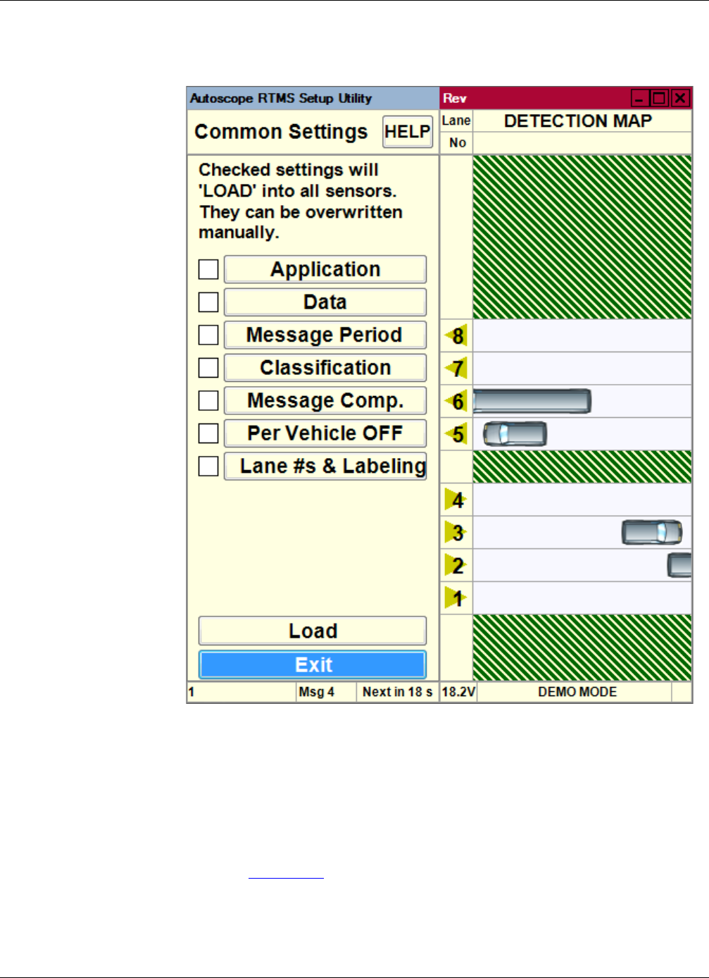
Chapter 5: Common Setup Options
RTMS Sx-300 User Guide ©2014 Image Sensing Systems Inc. 5-6
The following screen appears.
9. To see what the current setting is for a parameter or to change it, click on the
parameter (Application, Data, etc.).
10. To use a parameter as a common setting, select the check box to the left.
11. To upload the common parameters to the Autoscope RTMS Sx-300 sensor, click
Load.
You are returned to the Main Screen.
12. Repeat Steps 5 – 11 for each Autoscope RTMS Sx-300 sensor.
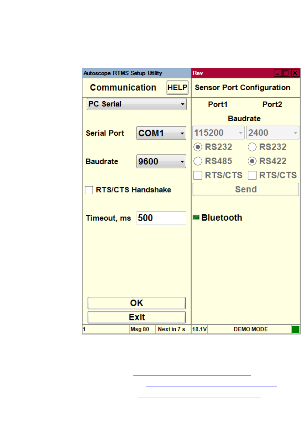
Chapter 5: Defining Communications
RTMS Sx-300 User Guide ©2014 Image Sensing Systems Inc. 5-7
Defining Communications
The Communication screen is used to define the communication method used
between your computer and the Autoscope RTMS Sx-300.This screen is also used to
troubleshoot data connections, and if need be, to modify an existing connection.
Figure 5-1: Communications Screen
The types of communication that can be defined are:
•Serial —See “Defining a Serial Connection” on page 5-9.
•Bluetooth — See “Defining a Bluetooth Connection” on page 5-11.
•Dialup — See “Defining a Dialup Connection” on page 5-13.
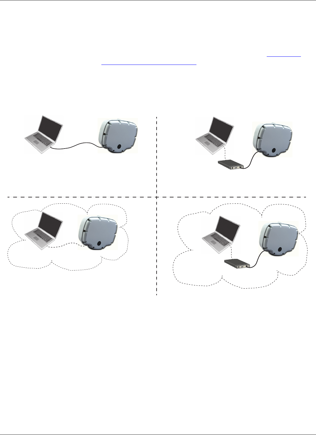
Chapter 5: Defining Communications
RTMS Sx-300 User Guide ©2014 Image Sensing Systems Inc. 5-8
•TCP/IP — This option must be used with the RTMS Sx-300-TCP models (see
the Autoscope RTMS Sx-300 Optional Configurations User Guide, PN
A900-1155-2). This option can also be used when the Autoscope RTMS
Sx-300 serial port is connected to an external Ethernet modem that the
Autoscope RTMS Setup Utility can communicate with (see “Defining a
TCP/IP Connection” on page 5-15).
NOTE: When the Communication screen appears, the left side of the screen is used
to define the connection you would like to make; the right side is used to
modify parameters after you are connected.
Figure 5-2: Autoscope RTMS Sx-300 Communication Connections
Autoscope RTMS Sx-300
Autoscope RTMS Sx-300
Autoscope RTMS Sx-300
Computer Serial cable
Serial Connection
Computer
Ethernet
modem
IP addressing
TCP/IP Connection
Computer
Autoscope RTMS Sx-300
Dialup
modem
Dialup Connection
Computer
Bluetooth Connection
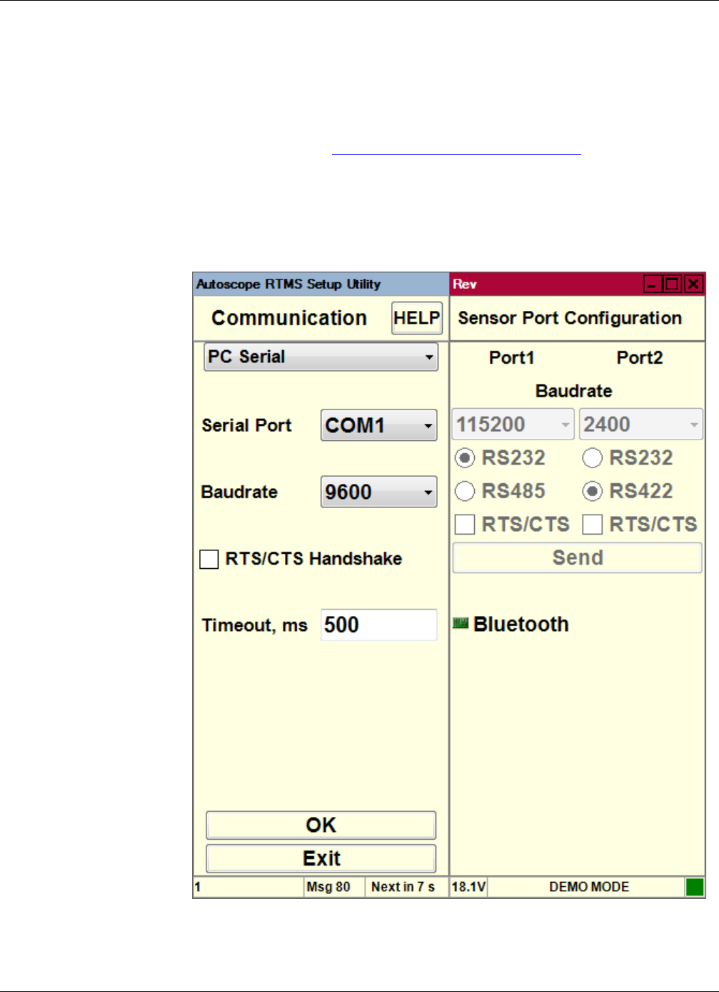
Chapter 5: Defining Communications
RTMS Sx-300 User Guide ©2014 Image Sensing Systems Inc. 5-9
Defining a Serial Connection
A serial connection is used when a serial cable connects the Autoscope RTMS Sx-300
sensor to the serial port on a computer running the Autoscope RTMS Setup Utility.
To define a serial connection, do the following.
1. Start the utility (see “Starting the Setup Utility” on page 3-7).
2. On the Main Screen, click Manual Settings.
3. On the Manual Setup screen, click Communication.
The following screen appears.
Note, you can also get to this screen by clicking the Communication button on
the Start screen.

Chapter 5: Defining Communications
RTMS Sx-300 User Guide ©2014 Image Sensing Systems Inc. 5-10
4. Select PC Serial from the drop-down at the top as the type of communication.
5. For Serial Port, select the computer port that will be used for communicating
with the Autoscope RTMS Sx-300.
6. For Baudrate, select the speed, in bits per second (bps) at which communication
is to take place.
The minimum is 2400, the maximum is 115200. The most common setting is
9600.
7. If handshaking is required, select the RTS/CTS Handshake check box.
NOTE: Make sure you have four wires for hardware handshake on your serial cable
if you use this option.
8. For Timeout, ms, enter the number of milliseconds to wait for communication
from the Autoscope RTMS Sx-300 before the connection times out.
9. When finished, click OK.
If a connection is established, the green COM indicator in the bottom right of the
screen will be blinking if the Autoscope RTMS Sx-300 sensor is in STAT or
Normal mode. The indicator does not blink if the sensor is in Polled mode unless
the Autoscope RTMS Setup Utility sends poll requests from the Start screen.
10. To return to the Manual Setup screen, click Exit.
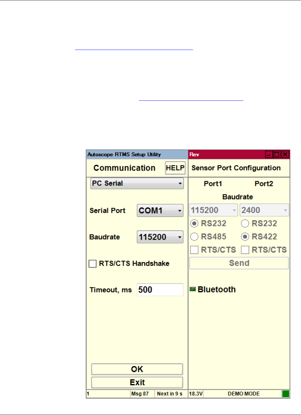
Chapter 5: Defining Communications
RTMS Sx-300 User Guide ©2014 Image Sensing Systems Inc. 5-11
Defining a Bluetooth Connection
The following describes how to define a bluetooth connection in the Autoscope
RTMS Setup Utility. For additional information on Bluetooth operations, see
Appendix D: “Bluetooth Device Operations”.
IMPORTANT: Bluetooth shares serial port 1 in the Autoscope RTMS Sx-300;
therefore, any physical connection to port 1 must be disconnected so
that communications to the Autoscope RTMS Sx-300 via bluetooth
can be established.
1. Start the utility (see “Starting the Setup Utility” on page 3-7).
2. On the Main Screen, click Manual Settings.
3. On the Manual Setup screen, click Communication.
The following screen appears.

Chapter 5: Defining Communications
RTMS Sx-300 User Guide ©2014 Image Sensing Systems Inc. 5-12
Note, you can also get to this screen by clicking the Communication button on
the Start screen.
4. Select PC Serial from the drop-down at the top as the type of communication.
5. For Serial Port, select the serial port that was assigned to the Bluetooth serial port
interface (see Appendix D: “Bluetooth Device Operations”).
6. For Baudrate, select 115200 (this is mandatory for Bluetooth).
7. Make sure the RTS/CTS Handshake check box is unchecked (not selected)
8. For Timeout, ms, enter the number of milliseconds to wait for communication
from the Autoscope RTMS Sx-300 before the connection times out.
9. When finished, click OK.
If a connection is established, the green COM indicator in the bottom right of the
screen will be blinking if the Autoscope RTMS Sx-300 sensor is in STAT or
Normal mode. The indicator does not blink if the sensor is in Polled mode unless
the Autoscope RTMS Setup Utility sends poll requests.
10. To return to the Manual Setup screen, click Exit.
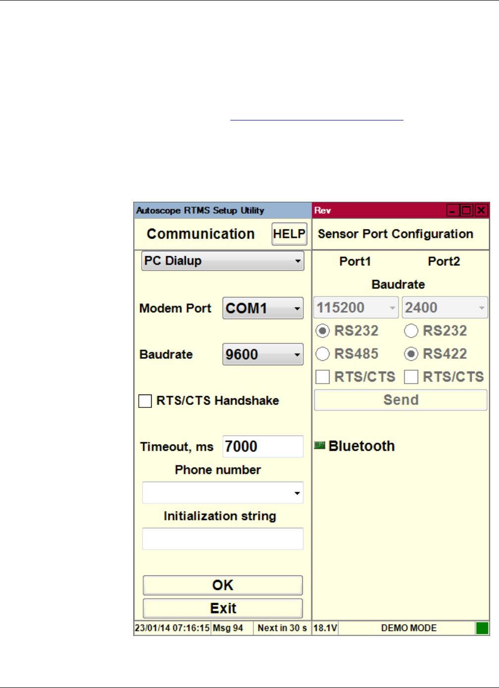
Chapter 5: Defining Communications
RTMS Sx-300 User Guide ©2014 Image Sensing Systems Inc. 5-13
Defining a Dialup Connection
In this type of connection, a modem must be connected to the serial port on the
Autoscope RTMS Sx-300 and the computer with the Autoscope RTMS Setup Utility
must be able to contact the modem, usually through its own internal modem.
To define a dialup connection, do the following.
1. Start the utility (see “Starting the Setup Utility” on page 3-7).
2. On the Main Screen, click Manual Settings.
3. On the Manual Setup screen, click Communication.
The following screen appears.

Chapter 5: Defining Communications
RTMS Sx-300 User Guide ©2014 Image Sensing Systems Inc. 5-14
Note, you can also get to this screen by clicking the Communication button on
the Start screen.
4. Select PC Dialup from the drop-down at the top as the type of communication.
5. For Modem Port, select the serial port that your dialup modem is configured to
use.
6. For Baudrate, select the speed, in bits per second (bps) of the dialup modem.
7. If your connection requires handshaking, select the RTS/CTS Handshake check
box.
NOTE: Make sure you have four wires for hardware handshake on your serial cable
if you use this option.
8. For Timeout, ms, enter the number of milliseconds to wait for communication
from the Autoscope RTMS Sx-300 before the connection times out.
NOTE: The default value (7000) is recommended.
9. In the Phone Number field, enter or select the phone number that your modem
needs to call.
10. If your modem requires an initialization string, enter it in the Initialization String
field.
11. When finished, click OK.
If a connection is established, the green COM indicator in the bottom right of the
screen will be blinking if the Autoscope RTMS Sx-300 sensor is in STAT or
Normal mode. The indicator does not blink if the sensor is in Polled mode unless
the Autoscope RTMS Setup Utility sends poll requests.
12. To return to the Manual Setup screen, click Exit.
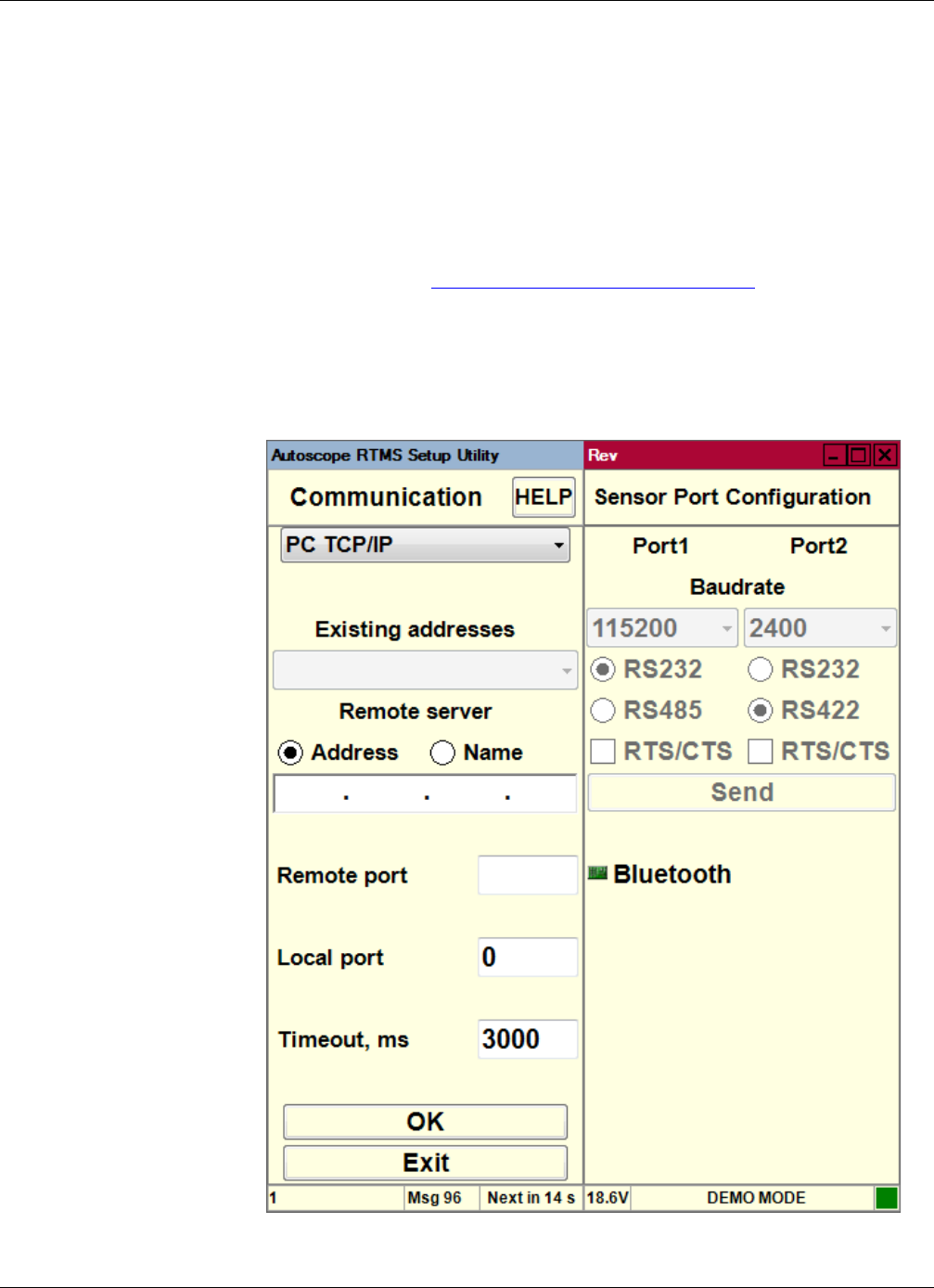
Chapter 5: Defining Communications
RTMS Sx-300 User Guide ©2014 Image Sensing Systems Inc. 5-15
Defining a TCP/IP Connection
NOTE: This type of connection can only be made when the Autoscope RTMS
Sx-300 serial port is connected to an external Ethernet modem that the
Autoscope RTMS Setup Utility can communicate with, or when used with
the RTMS Sx-300-CAM or RTMS Sx-300-TCP models (see the Autoscope
RTMS Sx-300 Optional Configurations User Guide, PN A900-1155-2).
To define a TCP/IP connection, do the following.
1. Start the utility (see “Starting the Setup Utility” on page 3-7).
2. On the Main Screen, click Manual Settings.
3. On the Manual Setup screen, click Communication.
The following screen appears.

Chapter 5: Defining Communications
RTMS Sx-300 User Guide ©2014 Image Sensing Systems Inc. 5-16
Note, you can also get to this screen by clicking the Communication button on
the Start screen.
4. Select PC TCP/IP from the drop-down at the top as the type of communication.
5. For Remote server, select Address.
6. Enter the IP address or name of the Autoscope RTMS Sx-300.
7. For Remote port, enter the port number to be used. Default is 2000.
8. For Local port, use the default of 0.
9. For Timeout, ms, enter the number of milliseconds to wait for communication
from the Autoscope RTMS Sx-300 before the connection times out.
NOTE: The default value (3000) is recommended.
10. Click OK.
11. To return to the Manual Setup screen, click Exit.
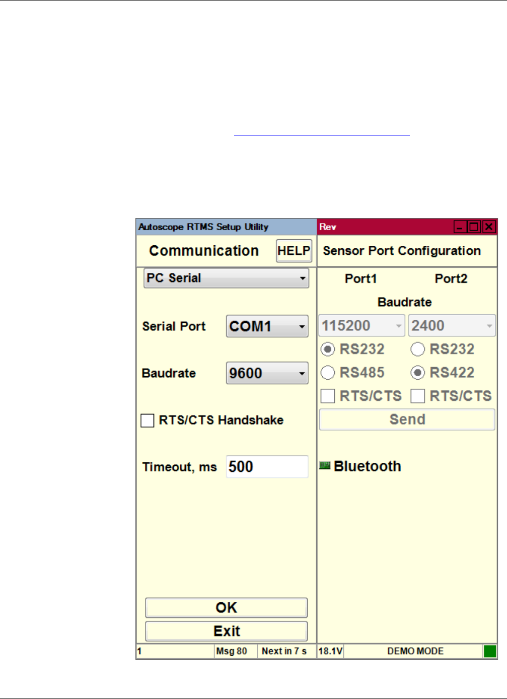
Chapter 5: Defining Communications
RTMS Sx-300 User Guide ©2014 Image Sensing Systems Inc. 5-17
Changing an Existing Connection
Normally, the Autoscope RTMS Setup Utility connects to the last known Autoscope
RTMS Sx-300 connection (e.g., COM1). If there are Autoscope RTMS Sx-300
sensors connected through different communication ports (e.g., COM3, TCP/IP, etc.),
the connection type must be established manually.
To make changes to an existing connection, do the following.
1. Start the utility (see “Starting the Setup Utility” on page 3-7).
2. On the Main Screen, click Manual Settings.
3. On the Manual Setup screen, click Communication.
The following screen appears.

Chapter 5: Defining Communications
RTMS Sx-300 User Guide ©2014 Image Sensing Systems Inc. 5-18
4. Once a connection is made, in the right pane you can:
•Alter communication speed (baudrate).
– 115200 bits per second (bps) is the factory default for serial units.
– Data rates below 9600 are useful where high quality transmission lines
are not available. When using data rates below 9600 bps, the Autoscope
RTMS Sx-300 data mode must be set to STAT to reduce the amount of
data and prevent communication problems. See “Changing the Data
Mode” on page 5-2 for further details.
•Change whether the connection is RS-232 or RS-485.
•Activate RTS/CTS handshaking if the cable used for the connection is wired
for it.
5. When finished, click Send.
NOTE: Once you change the settings, you may lose the connection to the Autoscope
RTMS Sx-300. If this happens, enter the connection parameters on the left
side of the screen and click OK.
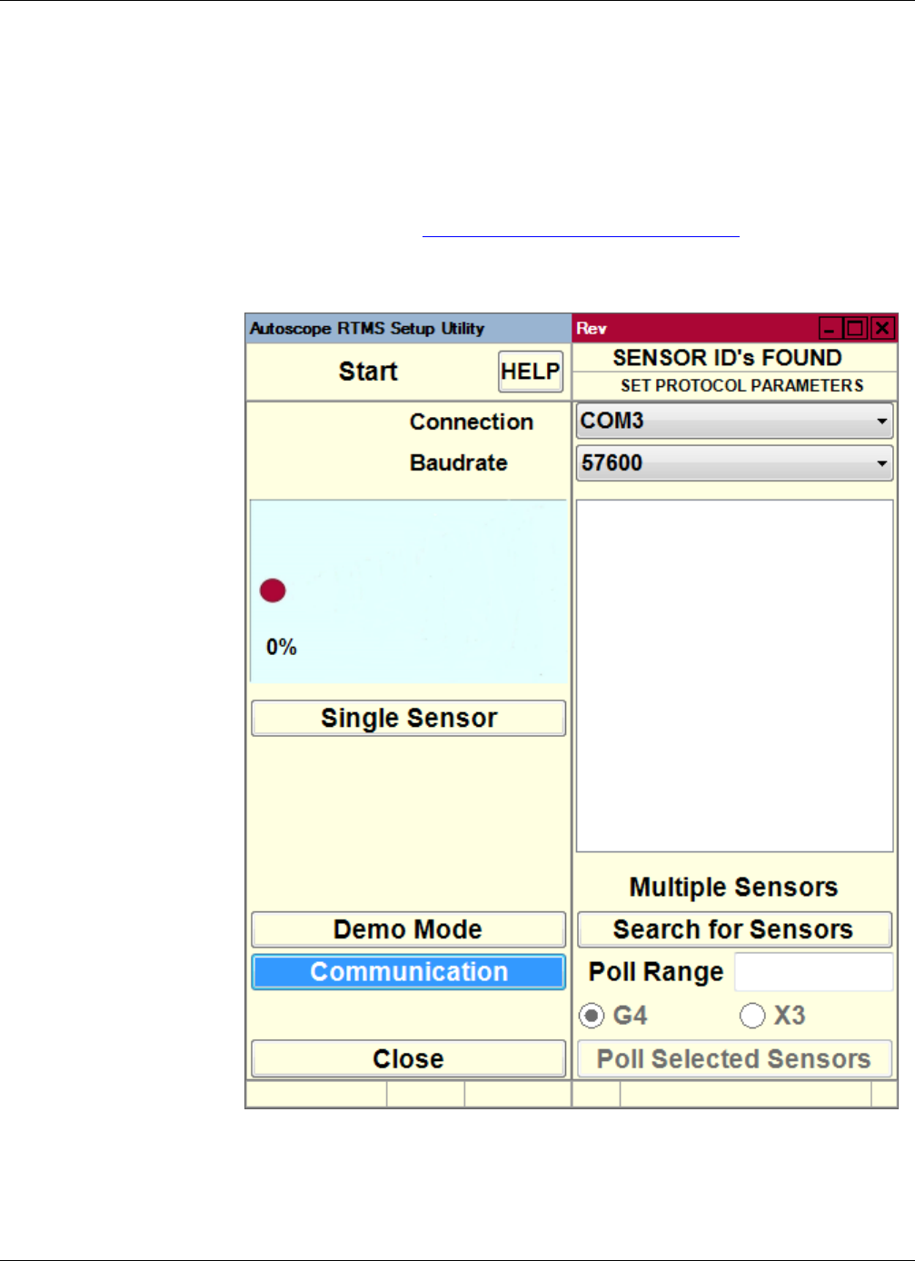
Chapter 5: Finding Sensors
RTMS Sx-300 User Guide ©2014 Image Sensing Systems Inc. 5-19
Finding Sensors
This option is used when an Autoscope RTMS Sx-300 sensor is not found by the
Autoscope RTMS Setup Utility when it starts up. This includes Autoscope RTMS
Sx-300 sensors that might be in Polled mode.
NOTE: This procedure will also find any RTMS G4 sensors that are in the network.
1. Start the utility (see “Starting the Setup Utility” on page 3-7).
If an Autoscope RTMS Sx-300 unit is not found the Start screen appears.
2. Did the Start screen appear?
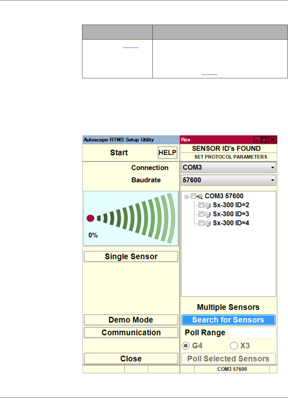
Chapter 5: Finding Sensors
RTMS Sx-300 User Guide ©2014 Image Sensing Systems Inc. 5-20
3. To begin the search, click Search for Sensors.
The search is conducted using the current communications options. Any
Autoscope RTMS Sx-300 units found appear in the list above “Multiple Sensors.”
Note, to change the communications option, click Communication to display the
Communication screen.
Yes No
Continue with Step 3. a) Close the Autoscope RTMS Setup Utility.
b) Start the utility and when the opening window
appears press ESC.
c) Continue with Step 3.

Chapter 5: Finding Sensors
RTMS Sx-300 User Guide ©2014 Image Sensing Systems Inc. 5-21
4. If the unit you are searching for appears in the list, or if no units appear after one
minute, click Stop Search.
5. Does the unit you are searching for appear in the list?
6. Do G4 sensors appear in the list along with Sx-300 sensors?
7. If the G4 sensor is the unit you want to configure, double-click it.
One of the following will occur.
•If the RTMS Setup Utility for G4 sensors is installed on your computer, it will
start up and the Main Screen will appear.
•If the RTMS Setup Utility for G4 sensors is not installed on your computer, a
message will appear indicating that you must install the utility in order to
configure the sensor. For more information, contact your sales or service
representative.
Yes No
Continue with Step 6. a) Troubleshoot the connection. See symptom
“Could not establish communications with
the Autoscope RTMS Sx-300” in Chapter 6:
“Troubleshooting”.
b) If the problem is resolved, continue with
Step 6; otherwise, contact Technical Support.
Yes No
Continue with Step 7. Select the unit from the list and click Single
Autoscope RTMS Sx-300 or double-click the unit
in the list. The Main Screen will appear with the
settings for the selected Autoscope RTMS Sx-300.
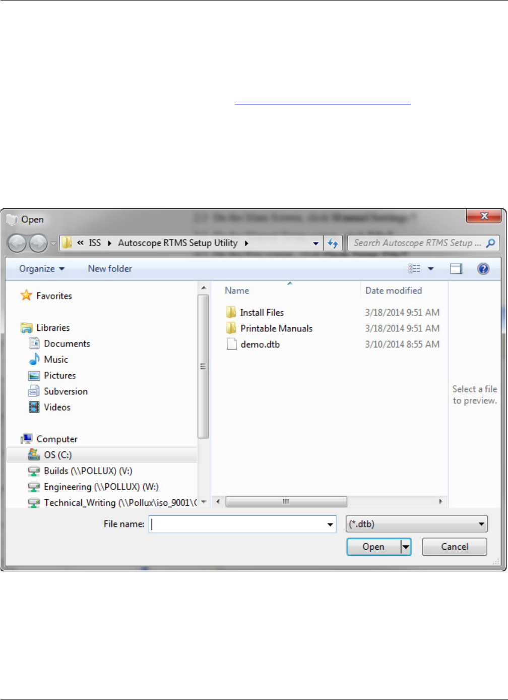
Chapter 5: Loading a Previously Saved Setup File
RTMS Sx-300 User Guide ©2014 Image Sensing Systems Inc. 5-22
Loading a Previously Saved Setup File
This option enables you to open a saved setup file and load it into the Autoscope
RTMS Sx-300. This option can be used to restore a configuration that has been
modified to its original settings.
1. Start the utility (see “Starting the Setup Utility” on page 3-7).
2. On the Main Screen, click Manual Settings.
3. On the Manual Setup screen, click File.
4. On the File screen, click Open Setup File.
The Open window appears.
5. Locate and select the setup file.
6. Click Open.
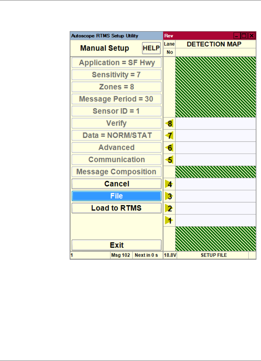
Chapter 5: Loading a Previously Saved Setup File
RTMS Sx-300 User Guide ©2014 Image Sensing Systems Inc. 5-23
The following screen appears.
The greyed out options show the settings in the file that will be loaded into the
Autoscope RTMS Sx-300.
7. If everything is correct, click Load to RTMS.
The configuration is loaded into the Autoscope RTMS Sx-300.
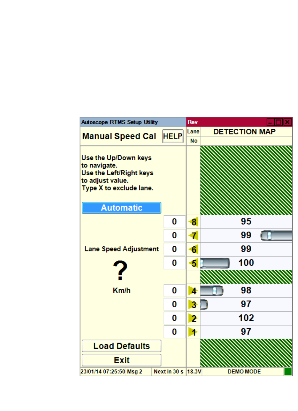
Chapter 5: Manual Speed Calibration
RTMS Sx-300 User Guide ©2014 Image Sensing Systems Inc. 5-24
Manual Speed Calibration
A two-person team is required for this procedure.
NOTE: This procedure should only be performed:
• If the automated speed calibration fails (the percentage difference for Step 8
on page 19 is more than ±10%).
•When volumes are too low for automatic calibration.
1. On the Speed Calibration screen, Click Manual
The following screen appears.
2. Select the zone number for which the speed is to be adjusted.

Chapter 5: Memory Operations
RTMS Sx-300 User Guide ©2014 Image Sensing Systems Inc. 5-25
3. Use the right and left arrow keys on your keyboard to increase or decrease the
reference speed by the value listed in the Speed Difference (LIDAR - Autoscope
RTMS Sx-300) field on the worksheet.
NOTE: If there was no volume detected over the previous message period the
Autoscope RTMS Setup Utility will not accept any manual adjustments to
speed. You can only adjust after a message period in which vehicles were
detected and a speed calculated.
4. Repeat Step 2 and Step 3 for each zone
5. Wait for two message periods to let the Autoscope RTMS Sx-300 speeds adjust.
6. Repeat “Step 5C: Check Calibration” on page 4-18 for each zone until the
percentage difference is less than ±10%.
Memory Operations
The Autoscope RTMS Sx-300 sensor has 8 MB of internal memory that can be used to
store statistical and per vehicle messages for later download.
The memory operations that can be performed are:
•Defining whether and how data (messages) is to be stored in the internal
memory of the Autoscope RTMS Sx-300.
•Downloading the stored data from internal memory to a computer.
•Clearing the internal memory (erase all data) of the Autoscope RTMS Sx-300.
Defining Memory Options
This operation enables you to define whether or not statistical and per vehicle
messages are saved and stored in the Autoscope RTMS Sx-300 memory, and whether
the oldest messages should be overwritten when the memory becomes full.
NOTES:
•It is recommended that this option always be enabled if there are
communications issues caused by the network. This allows data to be
retrieved from the time period when the communications was down.
•Activation of memory automatically selects Real Time Clock in message
composition for X3 STAT protocol.
•Enabling Store Into Memory when the Per Vehicle option is active (ON), will
cause the internal memory of the Autoscope RTMS Sx-300 sensor to fill up
faster.
To define the memory option, do the following.
1. Start the utility (see “Starting the Setup Utility” on page 3-7).
2. On the Main Screen, click Internal Memory.
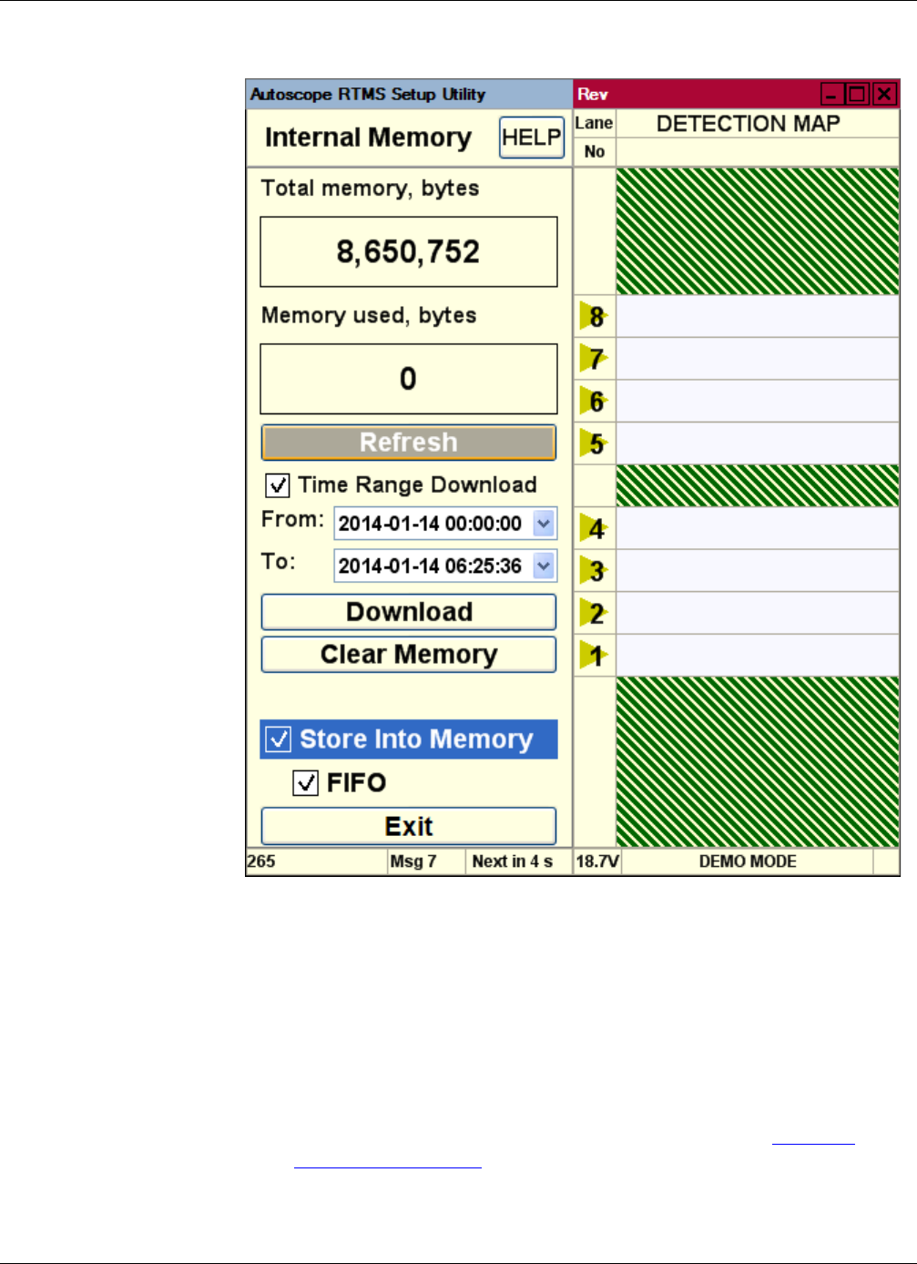
Chapter 5: Memory Operations
RTMS Sx-300 User Guide ©2014 Image Sensing Systems Inc. 5-26
The following screen appears.
3. To enable storage of Autoscope RTMS Sx-300 data in the Autoscope RTMS
Sx-300 onboard memory, select the Store Into Memory check box.
4. Use the FIFO check box to determine what action is to be taken once the sensors’
internal memory is full.
•FIFO selected: when memory is full, messages will continue to be stored but
the earliest stored messages will the overwritten.
•FIFO not selected: when memory is full, no more messages will be stored in
internal memory. In this case, the only ways to start saving messages again is
to either select the check box or clear internal memory (see “Clearing
Memory” on page 5-30).
5. To save the settings and return to the Main screen, click Exit.

Chapter 5: Memory Operations
RTMS Sx-300 User Guide ©2014 Image Sensing Systems Inc. 5-27
Downloading Autoscope RTMS Sx-300 Memory
Once data is stored in the Autoscope RTMS Sx-300 memory, you have the option of
downloading all or part of the data to the hard drive of a computer.
The following should be considered, especially when downloading large amounts of
memory.
•Download at the highest connection speed available when directly connected
to the Autoscope RTMS Sx-300 sensor. A full memory will take just over 12
minutes to download at 115200 bps with an RS-232 serial connection.
•If downloading at 115200 bps, ensure that the cable length is no longer than
15 m (50 ft). Otherwise, data corruption is possible.
NOTE: When a download is in progress, no other operations can be performed.
To download the messages stored in memory, do the following.
1. Start the utility (see “Starting the Setup Utility” on page 3-7).
2. On the Main Screen, click Internal Memory.
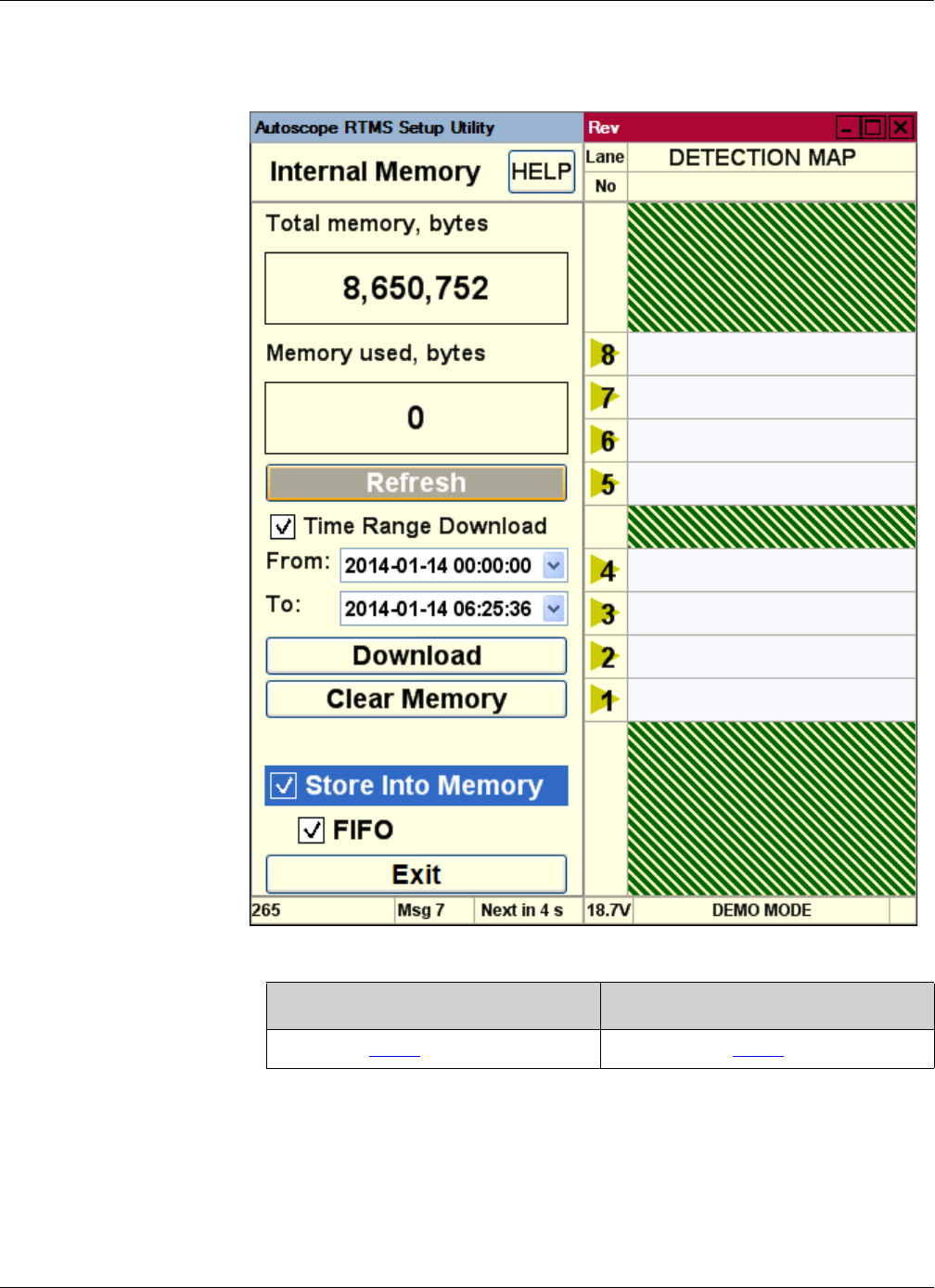
Chapter 5: Memory Operations
RTMS Sx-300 User Guide ©2014 Image Sensing Systems Inc. 5-28
The following screen appears.
3. Do you want to download all of memory or part of it?
4. Select the Time Range Download check box.
5. In the From field, set the date and time from which the download is to start.
•To set the date, select it from the drop-down menu.
•To set the time, select the appropriate field (hours, minutes, seconds) then use
the keyboard to enter a new time.
All Part
Proceed to Step 7. Continue with Step 4.

Chapter 5: Memory Operations
RTMS Sx-300 User Guide ©2014 Image Sensing Systems Inc. 5-29
6. In the To field, set the date and time at which the download is to end
Note, if you specify a To date beyond the current date, the Download button will
not be active.
7. Click Download.
8. When the Save As window appears, do the following.
a) In the Save in field, select the location where the file is to be saved.
b) In the File name field, type a name for the file.
c) In the Save as type field, select:
–Text files (*.asc) for human-readable format
–Binary files (*.bin) for machine readable, binary format
–Text and Binary files (*.asc, *.bin) for both formats
d) Click Save.
9. When the download is complete, click Exit to return to the Main screen.
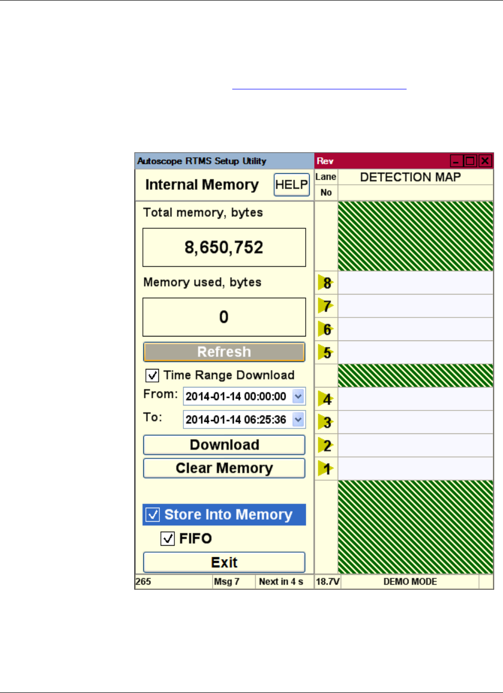
Chapter 5: Memory Operations
RTMS Sx-300 User Guide ©2014 Image Sensing Systems Inc. 5-30
Clearing Memory
This operation enables you to clear (erase) all of the messages that are stored in the
Autoscope RTMS Sx-300 internal memory.
1. Start the utility (see “Starting the Setup Utility” on page 3-7).
2. On the Main Screen, click Internal Memory.
The following screen appears.
3. Click Clear Memory.
All messages are erased and the count for Memory used, bytes is set to zero (0).
4. To return to the Main screen, click Exit.

Chapter 5: Message Operations
RTMS Sx-300 User Guide ©2014 Image Sensing Systems Inc. 5-31
Message Operations
There are three different operations that have an effect on the messages that are sent
by the Autoscope RTMS Sx-300 sensor:
•Defining the message composition
•Defining per vehicle messages
•Changing the frequency at which messages are sent
Defining the Message Composition
This operation defines the format of the statistical message (G4 or X3) and what data
is to be included in the message. For information about setting the composition of the
message, see “Step 6: Define Message Composition” on page 4-20.
Defining Per Vehicle Messages
When the Per Vehicle option is turned ON, a message is sent for every vehicle when it
is detected.
In the data file (see Appendix C: “Data Files and Message Formats”) the per vehicle
data is listed between the statistical messages that are sent for each message period
(see Figure C-4 on page C-5). The per vehicle data will add up to the same values that
are listed in the statistical message.
When Per Vehicle is ON, the per vehicle data is sent in between the regular statistical
messages. The data provided is as follows:
•Autoscope RTMS Sx-300 ID - ID number assigned to the sensor
•Lane - the zone where the vehicle was detected
•Class - the vehicle classification (small, medium, truck, etc.)
•Speed - the detected speed of the vehicle
•Length - the length of the vehicle
•Dwell - amount of time, in milliseconds, the vehicle is being detected
NOTE: If the Autoscope RTMS Sx-300 sensor is set to polled mode (see “Changing
the Data Mode” on page 5-2) with Per Vehicle turned ON, there will not be
any per vehicle data available in the live data stream. However, the per
vehicle data is available from internal memory downloads if the Store Into
Memory function is enabled (see “Defining Memory Options” on page 5-25).
To enable the Per Vehicle option, do the following.
1. On the Main Screen click Per Vehicle to turn the option ON or OFF.
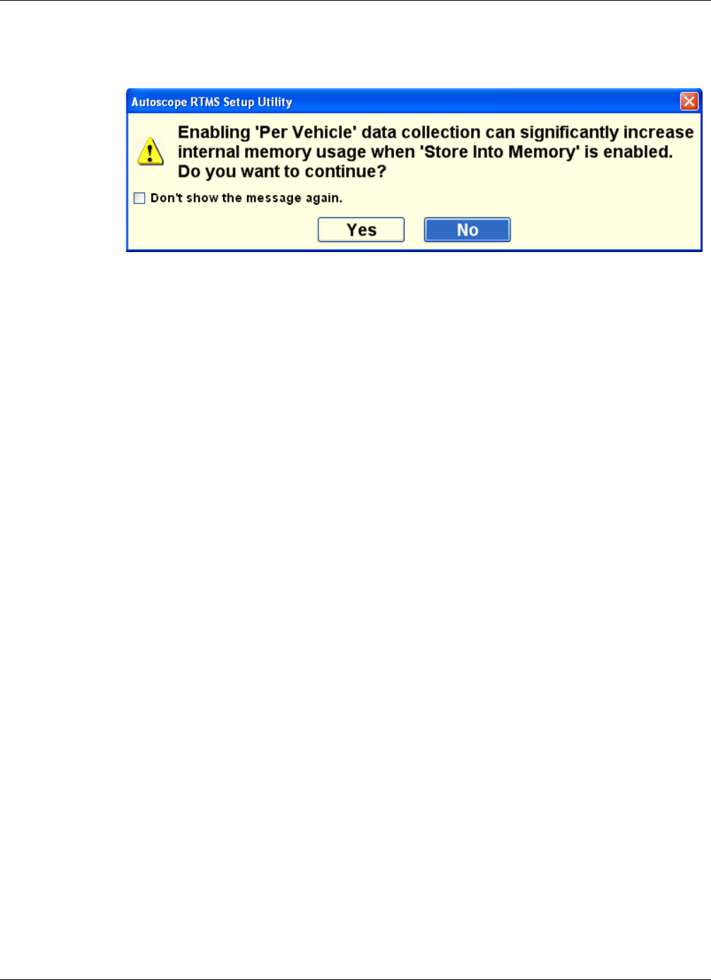
Chapter 5: Message Operations
RTMS Sx-300 User Guide ©2014 Image Sensing Systems Inc. 5-32
When the option is turned ON, the following window appears.
2. Click Ye s to enable (turn ON) the Per Vehicle option, or No to cancel the
operation.
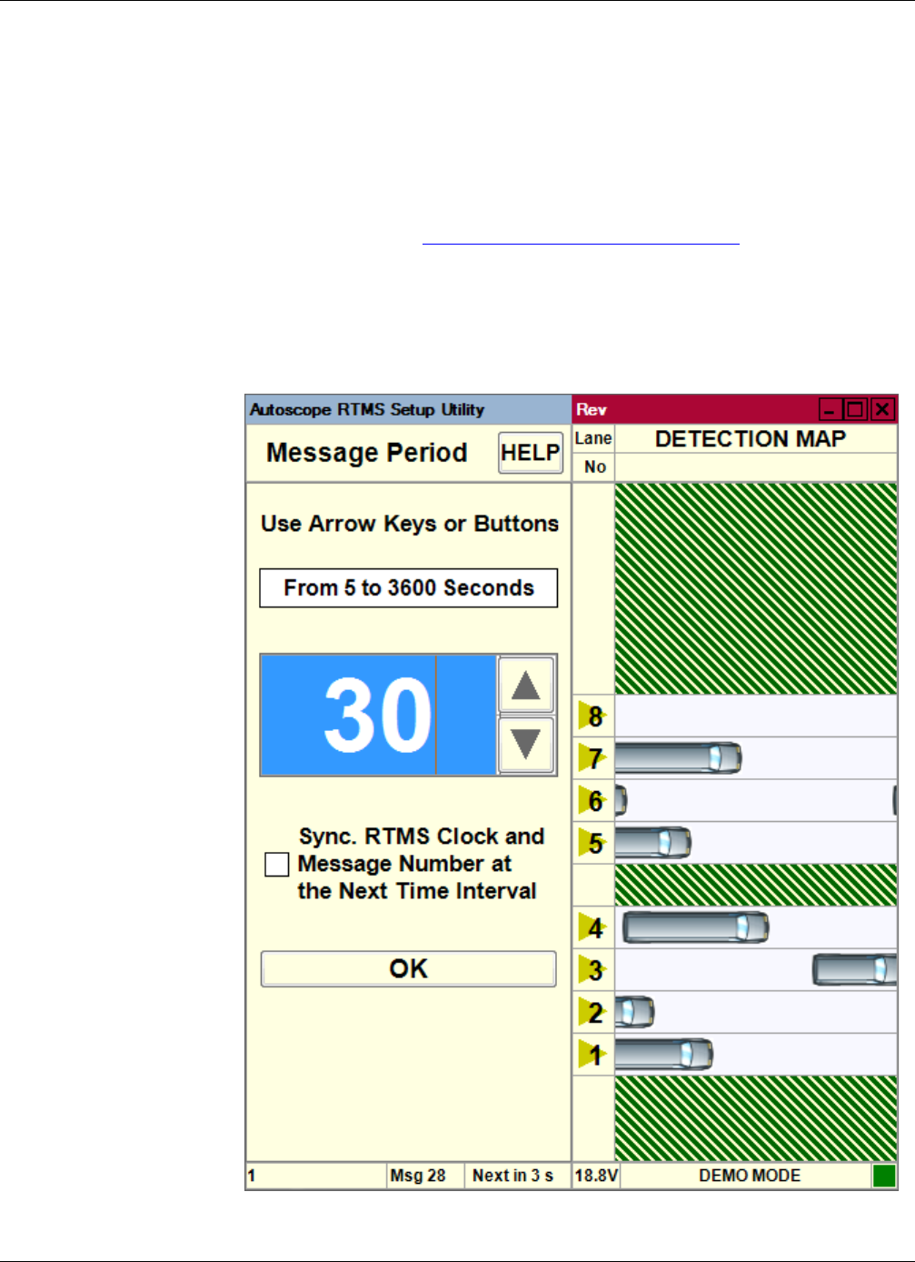
Chapter 5: Message Operations
RTMS Sx-300 User Guide ©2014 Image Sensing Systems Inc. 5-33
Changing the Message Period
The message period is the amount of time between sending statistical reports from the
Autoscope RTMS Sx-300. When the system is set up, a default period of 30 seconds is
used. This is the message period generally used for Real-Time traffic data. A 300 to
900 second period (5 to 15 min) is recommended for counting applications.
To change the message period, do the following.
1. Start the utility (see “Starting the Setup Utility” on page 3-7).
2. On the Main Screen, click Manual Settings.
3. On the Manual Setup screen, click Message Period.
The following screen appears.

Chapter 5: Optimizing Volume Count Accuracy
RTMS Sx-300 User Guide ©2014 Image Sensing Systems Inc. 5-34
4. Click the Up and Down arrows or use the arrow keys on your computer to set
Message Period to the desired interval.
For G4 STAT protocol the range is 5 to 3600 seconds. For X3 STAT protocol it is
5 to 900 seconds.
5. To synchronize the message with the Autoscope RTMS Sx-300 clock, select the
Sync check box.
Example: If the message period is set to 30 seconds, the message will be sent out
at 00:00:00 and 00:00:30; not at 00:00:03 or 00:00:33.
Note, this feature synchronizes the Autoscope RTMS Sx-300 clock and message
period with the connected PC. The program must be running to synchronize
Autoscope RTMS Sx-300.
6. Click OK.
The new value is set and you are returned to the Manual Setup screen.
Optimizing Volume Count Accuracy
The most common reasons for vehicle count discrepancies are:
•Zone boundaries overlap or are too close – When this occurs, vehicles in one
zone are shown as being detected in an adjacent zone. This is referred to as
“splashing.” In this case, changing the zone by increasing or decreasing the
boundary by one or more micro-slices can eliminate splashing.
•Improper sensor aiming – When this occurs vehicle counts are below what is
expected. If the sensor is aimed too low or high, or is not perpendicular to the
zone, vehicles may not be detected.
•Sensitivity too high or low – If the sensor is correctly aimed, incorrect counts
could be caused by an improper sensitivity setting.
•Obstruction between the sensor and zone – An obstruction, such as a concrete
lane divider may cause smaller vehicles to be missed.
•Occlusion – This is when a vehicle is hidden from view by another vehicle or
object. A large truck can occlude (hide) the detection of a small car hidden
behind.
The following provides information about the possible cause and solution for various
conditions that can cause inaccuracies in the volume count.
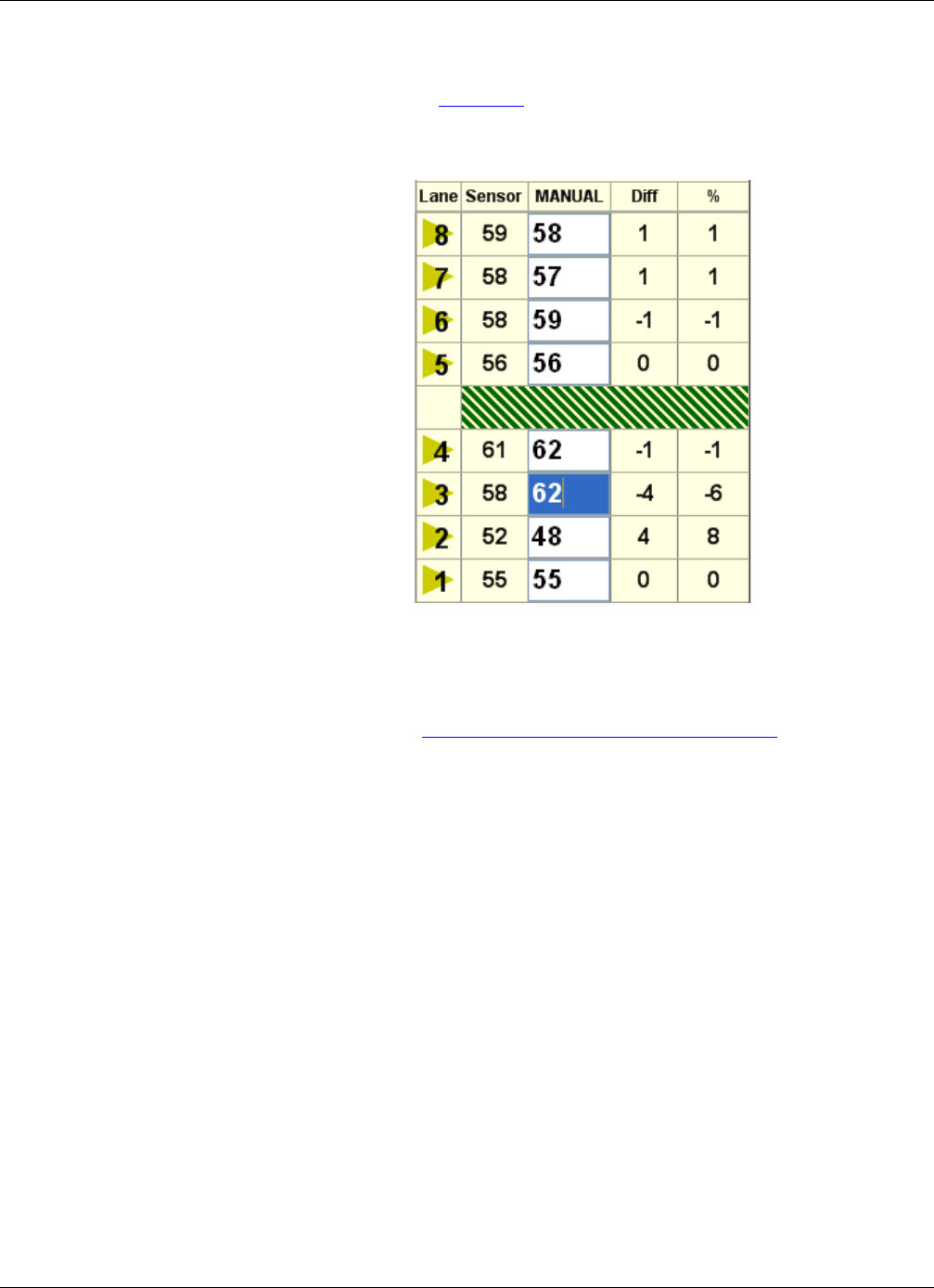
Chapter 5: Optimizing Volume Count Accuracy
RTMS Sx-300 User Guide ©2014 Image Sensing Systems Inc. 5-35
Condition A: Over/Under Count in Adjacent Zones
In the situation shown in Figure 5-3, zone 2 shows an over count, while zone 3 shows
and under count.
Figure 5-3: Over/Under Count: Adjacent Zones
The above could indicate that vehicles from zone 3 are being detected in zone 2. Fine
tune the zone boundary between the two zones by one micro-slice to begin with
(Move Closer –1). See “Adjusting Zone Boundaries” on page 5-55. Recheck the
results and adjust further if needed.
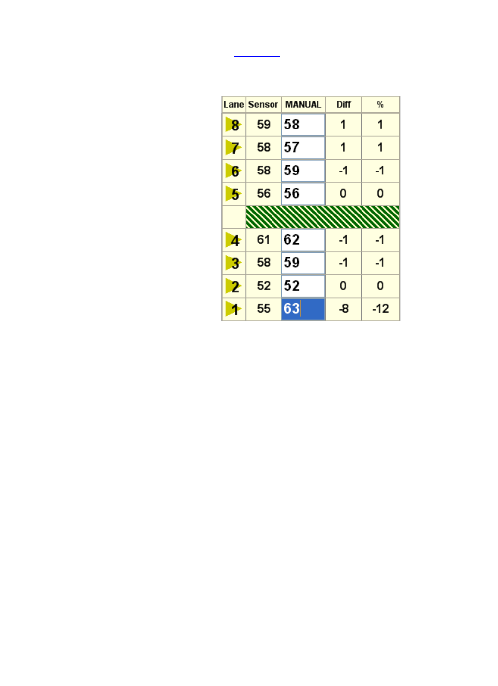
Chapter 5: Optimizing Volume Count Accuracy
RTMS Sx-300 User Guide ©2014 Image Sensing Systems Inc. 5-36
Condition B: Under Count in Near Zone
In the situation shown in Figure 5-4, the count for zone 1 is well below what is
expected; vehicles are being missed.
Figure 5-4: Under Count: Near Zone
The above is probably due to aiming issues. The sensor may be missing small profile
vehicles. Check the aiming of the Autoscope RTMS Sx-300 and make sure it is aimed
down enough to view the first lane of traffic (zone 1).
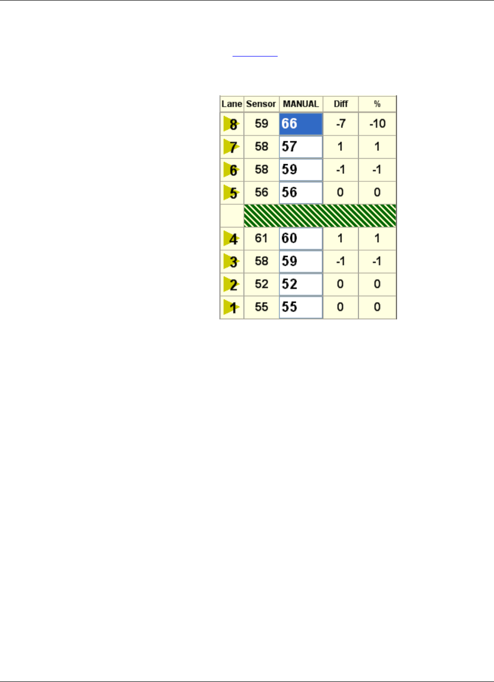
Chapter 5: Optimizing Volume Count Accuracy
RTMS Sx-300 User Guide ©2014 Image Sensing Systems Inc. 5-37
Condition C: Under Count in Far Zone
In the situation shown in Figure 5-5, the count for zone 8 is well below what is
expected; vehicles are being missed.
Figure 5-5: Under Count: Far Zone
The above is probably due to aiming issues. The sensor may be missing small profile
vehicles. Check the aiming of the Autoscope RTMS Sx-300 and make sure it is aimed
up enough to view the last lane of traffic (zone 8).

Chapter 5: Optimizing Volume Count Accuracy
RTMS Sx-300 User Guide ©2014 Image Sensing Systems Inc. 5-38
Condition D: Under Count in Several Zones
In the situation shown in Figure 5-6, the count for many zones is below what is
expected; vehicles are being missed.
Figure 5-6: Under Count: Many Zones
In the above situation the signal strength reflection may be too low. This could be
caused could by the following:
•The aiming angle is not perpendicular to the traffic.
•The sensitivity is too low.
Check the aiming angle. If this is OK, then increase the sensitivity (see “Sensitivity
Adjustment” on page 5-47).
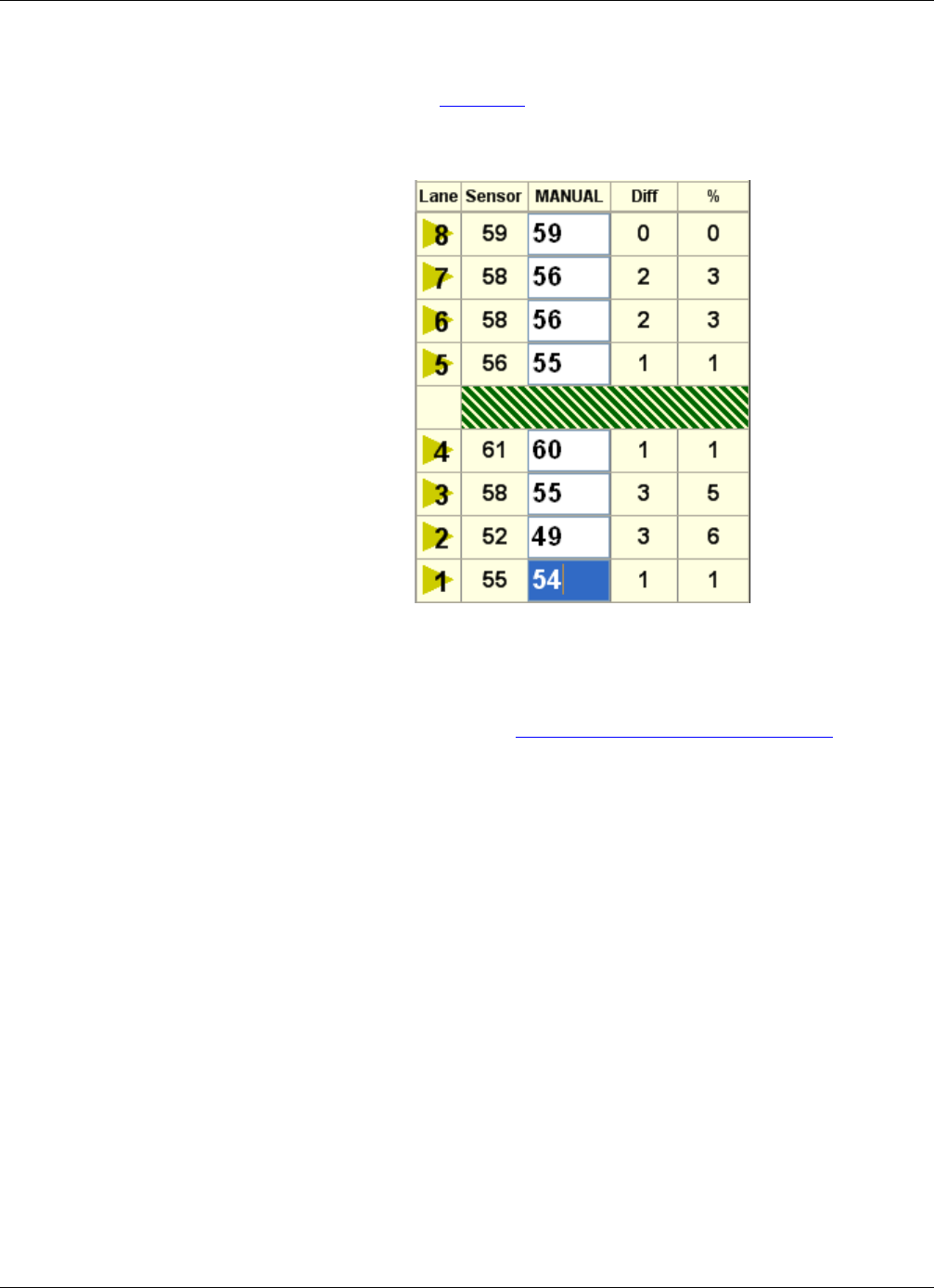
Chapter 5: Optimizing Volume Count Accuracy
RTMS Sx-300 User Guide ©2014 Image Sensing Systems Inc. 5-39
Condition E: Over Count in Several Zones
In the situation shown in Figure 5-7, the count for many zones is above what is
expected.
Figure 5-7: Over Count: Many Zones
In the above situation the signal strength reflection may be too high, causing
“splashing” into adjacent lanes. The most likely cause is that the sensitivity is too
high. Decrease the sensitivity (see “Sensitivity Adjustment” on page 5-47).
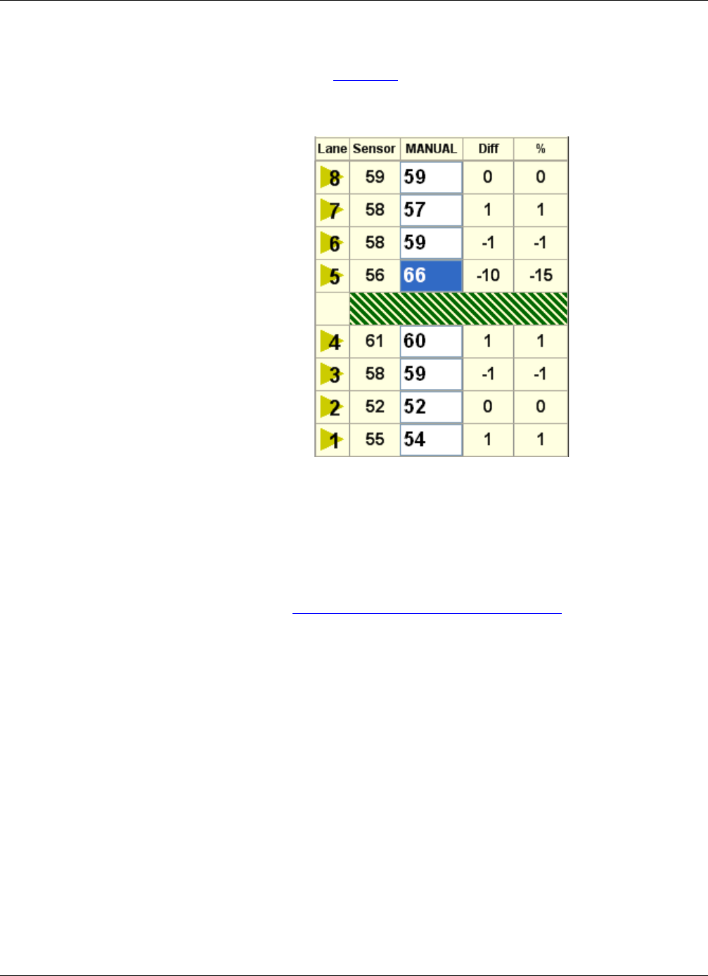
Chapter 5: Optimizing Volume Count Accuracy
RTMS Sx-300 User Guide ©2014 Image Sensing Systems Inc. 5-40
Condition F: Under Count in First Zone Past a Barrier
In the situation shown in Figure 5-8, the count for zone 5 is lower than what is
expected.
Figure 5-8: Under Count: First Zone Past Barrier
The above could indicate there is some kind of barrier between zones 4 and 5. The
signal from the barrier is imposing on zone 5, causing smaller vehicles to be missed.
Moving the zone boundary away from the barrier should help resolve this situation.
Fine tune zone 5 by moving the zone boundary closest to the barrier further away from
the barrier (move away +1). An adjustment of 1 or 2 micro-slices can make a large
improvement. See “Adjusting Zone Boundaries” on page 5-55. Recheck the results
and adjust further if needed.
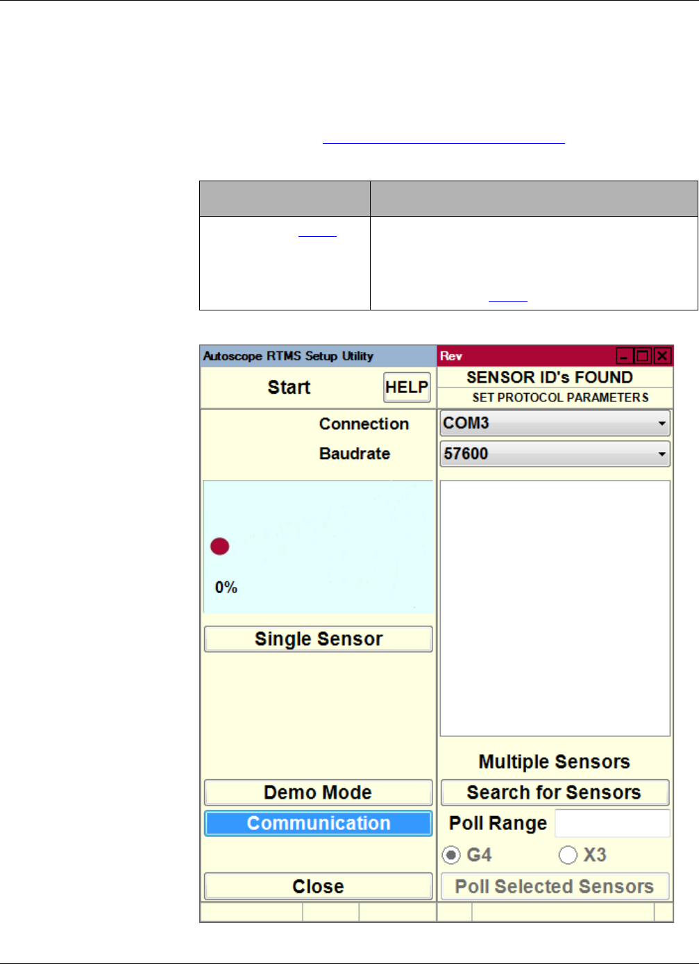
Chapter 5: Polling Sensors
RTMS Sx-300 User Guide ©2014 Image Sensing Systems Inc. 5-41
Polling Sensors
This option can be used to verify the operation of a single Autoscope RTMS Sx-300
sensor or multiple Autoscope RTMS Sx-300 sensors that share the same
communications line. The Autoscope RTMS Sx-300 units must be in polled mode.
1. Start the utility (see “Starting the Setup Utility” on page 3-7).
2. Did the Start screen or Main Screen appear?
Start Screen Main Screen
Continue with Step 3. a) Close the Autoscope RTMS Setup Utility.
b) Restart the utility but press the ESC key
immediately after the opening screen appears.
c) Continue with Step 3.
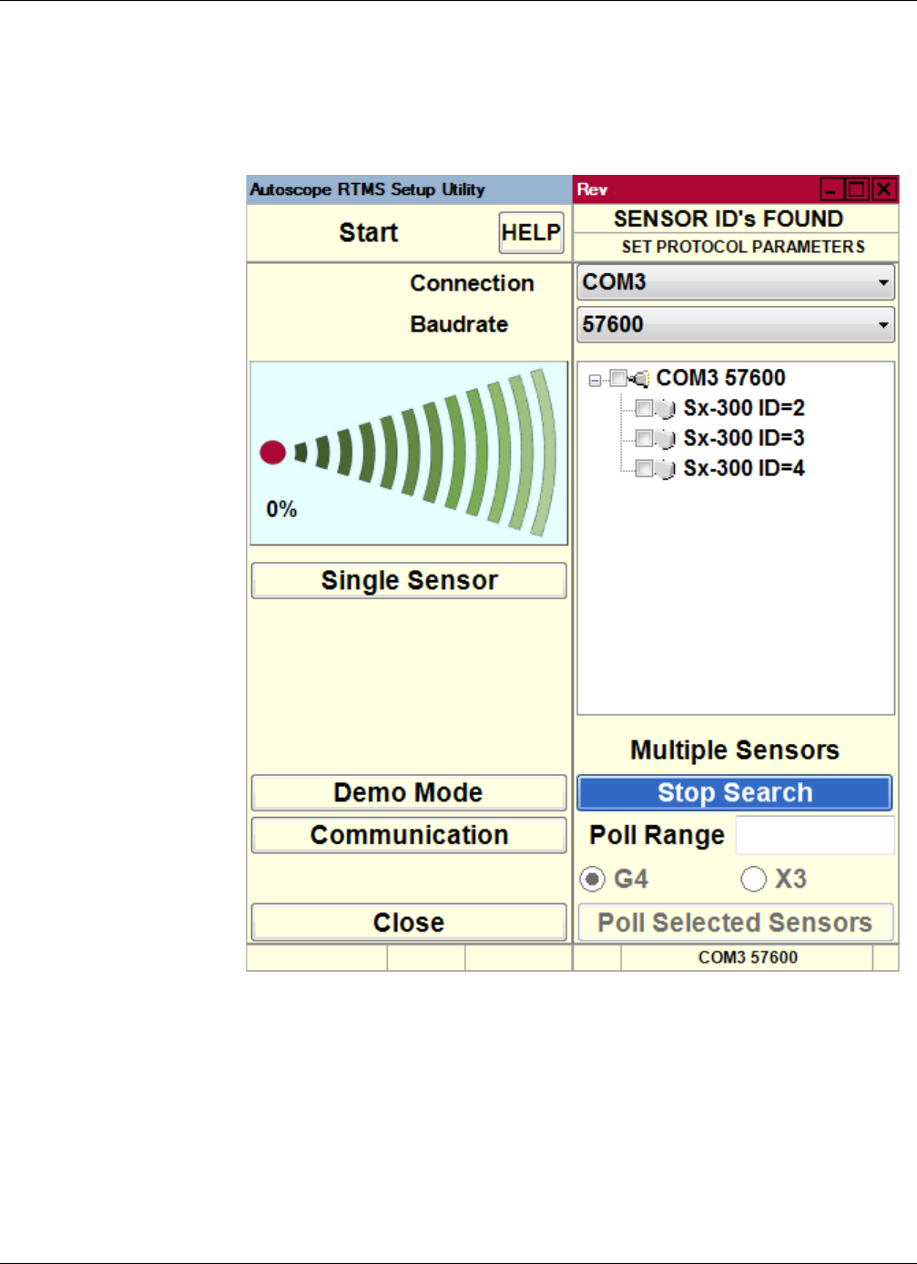
Chapter 5: Polling Sensors
RTMS Sx-300 User Guide ©2014 Image Sensing Systems Inc. 5-42
3. Click Search for Sensors.
Sensors that are found will appear in the list on the right side.
4. If all of the sensors you want to check appear in the list, click Stop Search to halt
the search.
5. In the Poll Range field, enter the starting and ending ID numbers, separated by a
dash or individual sensor IDs separated by a comma, of the units to be polled (e.g.,
1-4 indicates sensors 1 thru 4, while 1,3 indicates sensors 1 and 3).
6. Select the protocol type (G4 or X3) used to communicate with the Autoscope
RTMS Sx-300 sensors.
7. Click Poll Selected Sensors.
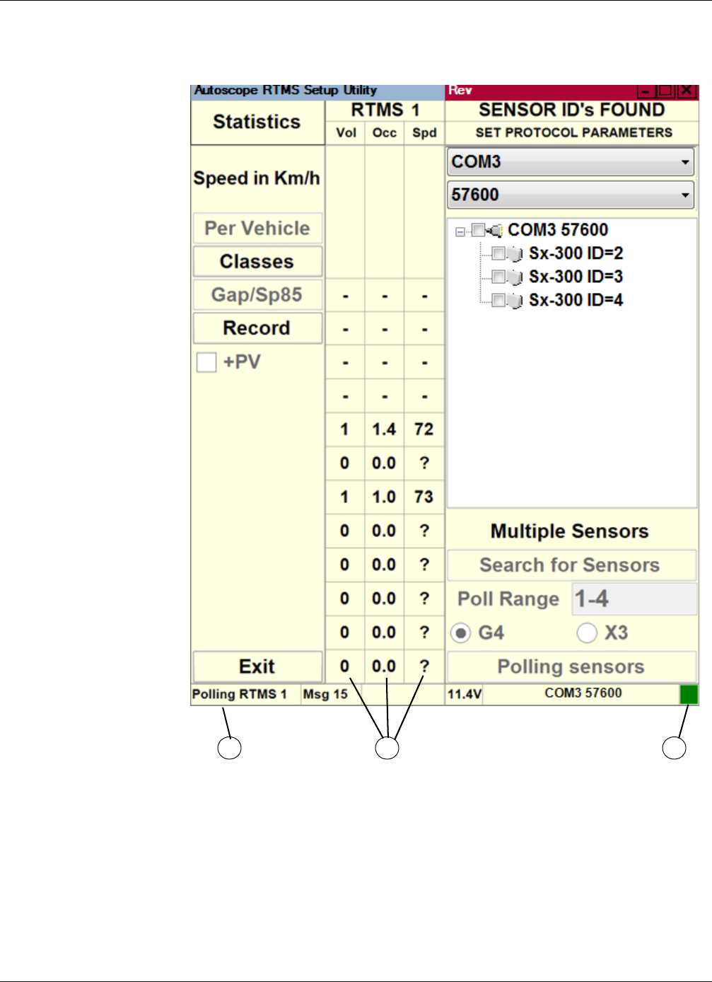
Chapter 5: Polling Sensors
RTMS Sx-300 User Guide ©2014 Image Sensing Systems Inc. 5-43
Statistics information is displayed, in turn, for each polled unit.
1 – Indicates which Autoscope RTMS Sx-300 sensor is being polled.
2 – The data that is displayed is for this sensor.
3 – When green, the sensor is connected to the computer. When flashing, data is
being exchanged between the computer and sensor. When red, the sensor is
not connected to or communicating with the computer.
1 2 3
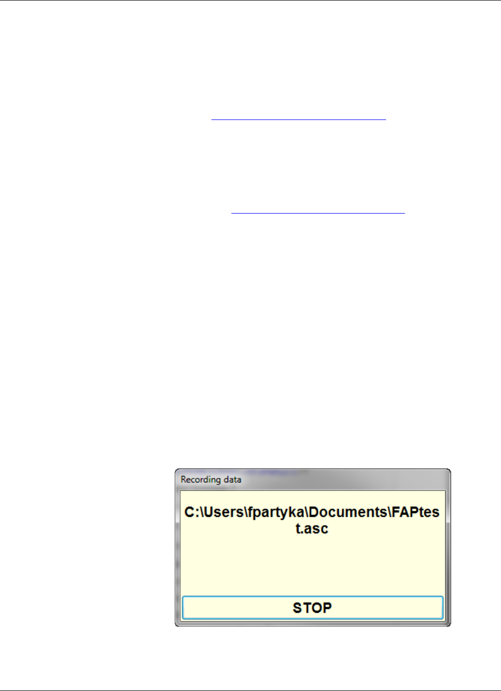
Chapter 5: Recording Data To a File
RTMS Sx-300 User Guide ©2014 Image Sensing Systems Inc. 5-44
Recording Data To a File
The Autoscope RTMS Setup Utility can record statistical and per vehicle data to a file
on the hard drive of the attached computer, a network drive, USB drive or other
storage media.
NOTE: The Record option is disabled if the Autoscope RTMS Sx-300 is set to Polled
mode (see “Changing the Data Mode” on page 5-2). The exception is when
Poll Selected Sensors is selected on the Start screen; in this case the
Statistics screen opens with the Record button enabled.
This option can be used to record data as it becomes available and would not require
additional time to perform a download from the internal memory later on. This
requires an uninterrupted communication link to the Autoscope RTMS Sx-300 sensor.
1. Start the utility (see “Starting the Setup Utility” on page 3-7).
2. On the Main Screen, click Manual Settings.
3. On the Manual Setup screen, click File.
4. On the File screen, click Record Data.
5. When the Save As window appears, do the following.
a) In the Save in field, select the folder where the file is to be saved.
Note, the default location is recommended.
b) In the File name field, type a name for the file.
c) In the Save as type field, select:
–Text files (*.asc) for human-readable format
–Binary files (*.bin) for machine readable, binary format
–Text and Binary files (*.asc, *.bin) for both formats
6. Click Save.
A window similar to the following appears.
7. To stop recording, click Stop.
8. To return to the Manual Setup screen, click Back.

Chapter 5: Self Test
RTMS Sx-300 User Guide ©2014 Image Sensing Systems Inc. 5-45
Self Test
The Autoscope RTMS Sx-300 provides a diagnostic test of its internal functions
which can be used to verify that the Autoscope RTMS Sx-300 hardware components
are operating correctly. The test checks internal functions and locates hardware faults.
Please note:
•The All System OK message is displayed on the screen if no faults are found.
•For Autoscope RTMS Sx-300 sensors with the Contact Closure module, the
self-test will also close the zone contacts for one second each in sequence.
Operation of the contacts can then be verified using the controller display,
ohm-meter or any other suitable device showing continuity.
The following is a list of self-test messages describing a fault:
•Power supply fault
•Modulator signal fault
•Microwave module fault
•Modulator memory fault
•Program memory fault
•DSP fault
•Gain too low or ADC fault
•Logic failure
•No signal
•Saturation signal level
To perform the self test, do the following.
1. Start the utility (see “Starting the Setup Utility” on page 3-7).
2. On the Main Screen, click Self Test.
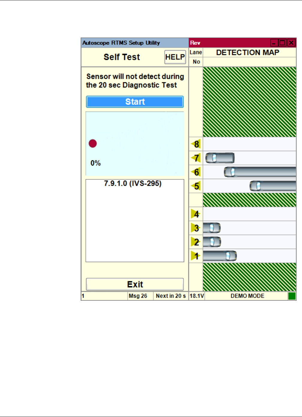
Chapter 5: Self Test
RTMS Sx-300 User Guide ©2014 Image Sensing Systems Inc. 5-46
The following screen appears.
3. To begin the test, click Start.
The self test results will display below the progress bar after approximately 20
seconds.
4. To stop the test and return to the Main Screen, click Exit.
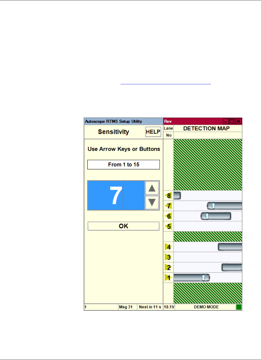
Chapter 5: Sensitivity Adjustment
RTMS Sx-300 User Guide ©2014 Image Sensing Systems Inc. 5-47
Sensitivity Adjustment
Sensitivity adjustments may be necessary to detect small vehicles, or to reduce
splashing. If small vehicles in close or in far lanes are being missed, adjust sensor aim
by tilting the sensor towards the zones with poor detection.
NOTE: Do not increase sensitivity to compensate for improper aiming.
The initial sensitivity setting is about 7, which is automatically set when you run the
Wizard. To adjust the level, do the following.
1. Start the utility (see “Starting the Setup Utility” on page 3-7).
2. On the Main Screen, click Manual Settings.
3. On the Manual Setup screen, click Sensitivity.
The following screen appears.
4. If needed, click the arrows to increase sensitivity to detect small vehicles, or
reduce sensitivity if a vehicle is causing “ghost” vehicles to be detected in
adjacent zones (splashing).
5. To save the setting and exit the screen, click OK.
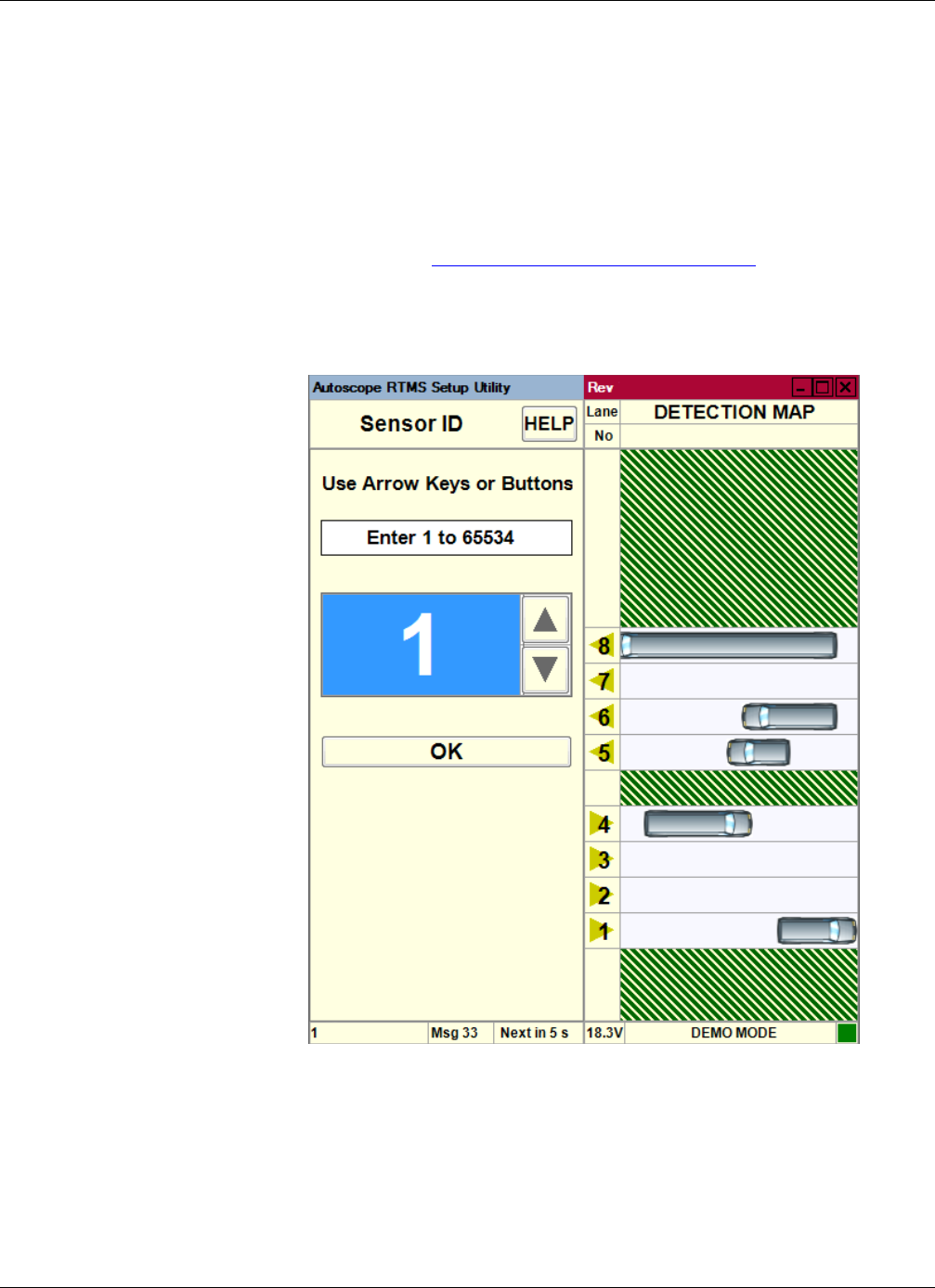
Chapter 5: Setting the Sensor ID
RTMS Sx-300 User Guide ©2014 Image Sensing Systems Inc. 5-48
Setting the Sensor ID
This function is used to assign an ID number to a sensor. It is recommended that you
number all sensors with consecutive numbers, starting at 1. Please consult your
sales/service representative for assistance when designing large networks.
IMPORTANT: If Polled Data mode is used, Autoscope RTMS Sx-300 sensors
should be assigned unique ID numbers to avoid data corruption.
1. Start the utility (see “Starting the Setup Utility” on page 3-7).
2. On the Main Screen, click Manual Settings.
3. On the Manual Setup screen, click Sensor ID.
The following screen appears.
4. Click the Up and Down arrows (or the arrow keys on your keyboard) to increase
or decrease the number.
•For G4 STAT protocol, the Sensor ID range is 1 - 65534
•For X3 STAT protocol, the Sensor ID range is 1 - 254.
NOTE: 255 and 65,535 are reserved and should not be used for sensor IDs.
5. Click OK.

Chapter 5: Updating the Setup Utility With a New Configuration
RTMS Sx-300 User Guide ©2014 Image Sensing Systems Inc. 5-49
Updating the Setup Utility With a New Configuration
This function enables you to read the configuration on the connected Autoscope
RTMS Sx-300 and update the Autoscope RTMS Setup Utility with the information.
This is required when connecting different Autoscope RTMS Sx-300 sensors to the
same communication port without closing the Autoscope RTMS Setup Utility first.
1. Start the utility (see “Starting the Setup Utility” on page 3-7).
2. On the Main Screen, click Manual Settings.
3. On the Manual Setup screen, click Read Autoscope RTMS Sx-300.
The Autoscope RTMS Setup Utility is updated with the configuration from the
Autoscope RTMS Sx-300.
Upgrading Firmware
The following describes the procedure for upgrading the firmware in an Autoscope
RTMS Sx-300 sensor.
NOTE: Do not attempt to upgrade without a solid communication channel. A direct
RS-232 connection to port 1 is recommended.
1. Start the utility (see “Starting the Setup Utility” on page 3-7).
2. On the Main Screen, click Manual Settings.
3. On the Manual Setup screen, click Advanced.
4. On the Advanced screen, click Firmware Upgrade.
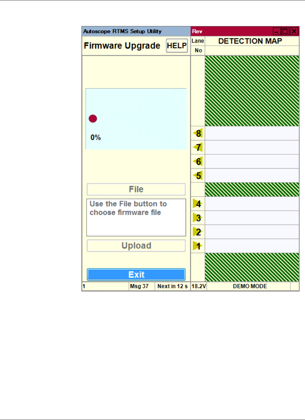
Chapter 5: Upgrading Firmware
RTMS Sx-300 User Guide ©2014 Image Sensing Systems Inc. 5-50
The following screen appears.
5. Check that the current firmware version is displayed on screen.
6. Click File.
7. Locate and select the firmware file to upload into the Autoscope RTMS Sx-300.
This is the .arf file; e.g., RTMS Sx-300_FW_8.0.0.0.arf.
8. Click Upload.
During upgrade, the progress bar advances and indicates Percentage Complete.
9. Wait for the message “Upgrade Succeeded”.
10. To return to the Manual Setup screen, click Exit twice.
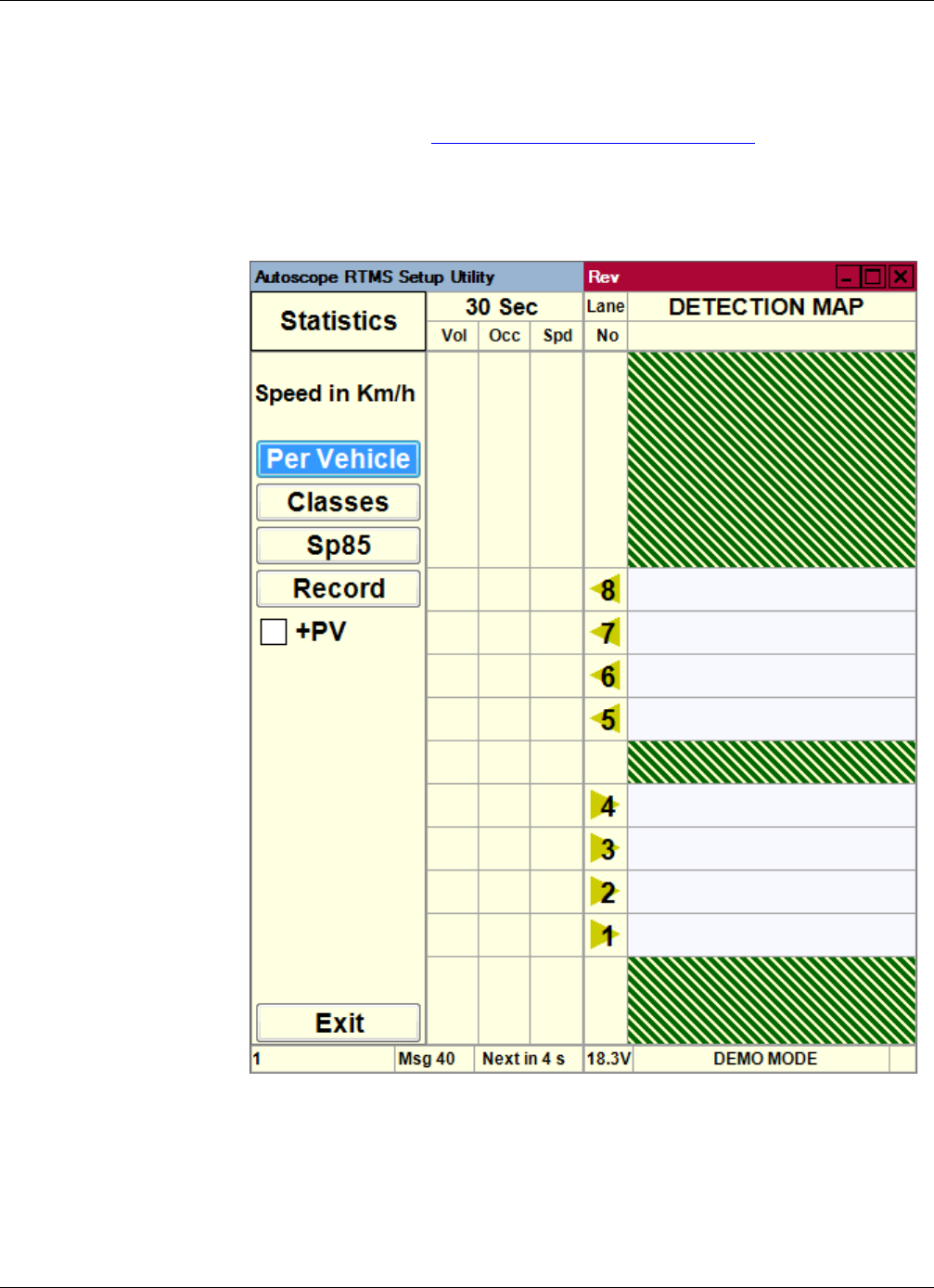
Chapter 5: Viewing Statistics
RTMS Sx-300 User Guide ©2014 Image Sensing Systems Inc. 5-51
Viewing Statistics
This option enables you to display traffic count information on the Statistics screen.
1. Start the utility (see “Starting the Setup Utility” on page 3-7).
2. On the Main Screen, click Statistics.
The following screen appears.
3. Select the appropriate option:
•Per Vehicle — Provides classification and speed information for each vehicle
as the vehicles are detected.
•Classes — Displays the number of vehicles from each class that are detected
during the message period.

Chapter 5: Zone Setup
RTMS Sx-300 User Guide ©2014 Image Sensing Systems Inc. 5-52
•Sp85 — Displays the 85th percentile speed for the most recent message
period. If GAP or Headway is selected for message composition, it will also
be displayed.
•Record — Records a stream of data that can typically be used for
troubleshooting. The data can be saved in the following formats:
–Text files (*.asc) for human-readable format
–Binary files (*.bin) for machine readable, binary format
–Text and Binary files (*.asc, *.bin) for both formats
On the Save screen you have the option of saving the data in both file formats
at the same time.
NOTE: The Record option is disabled if the Autoscope RTMS Sx-300 is set to Polled
mode (see “Changing the Data Mode” on page 5-2). The exception is when
Poll Selected Sensors is selected on the Start screen; in this case the
Statistics screen opens with the Record button enabled.
•+PV — select this option to observe per vehicle data as well as statistical
data.
•Exit — Returns to the Main Screen.
The displayed information is as follows:
•xx Sec — Indicates the number of seconds in the message period. The default
is 30 seconds.
•Vol — The total number of vehicles per zone.
•Occ — The percentage of lane occupancy for the message period.
•Spd — The average speed of traffic in the lane.
•Lane No — Displays the lane number.
•Detection Map — Displays a real-time visualization of traffic.
Zone Setup
After the initial configuration is complete, it may be necessary to add or delete zones,
or to adjust the boundaries of individual zones or sensitivity, such as when “splashing”
occurs or for accommodating wider merge lanes, etc. For information about sensitivity
see “Sensitivity Adjustment” on page 5-47.
Splashing occurs when a vehicle from one lane triggers a detection in another lane.
Lane changes are one cause of splashing. Narrow lanes or incorrect boundaries are
other common causes.
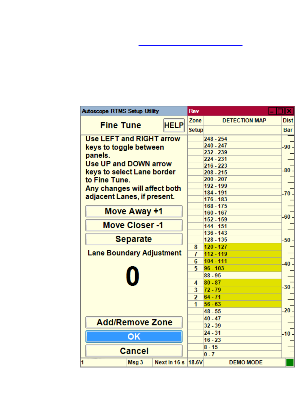
Chapter 5: Zone Setup
RTMS Sx-300 User Guide ©2014 Image Sensing Systems Inc. 5-53
Adding/Deleting Zones
To add or delete a zone to/from an existing configuration, do the following.
1. Start the utility (see “Starting the Setup Utility” on page 3-7).
2. On the Main Screen, click Manual Settings.
3. On the Manual Setup screen, click Zones.
4. On the Zone Setup screen, click Fine Tune.
The following screen appears.
5. Click Add/Remove Zone.
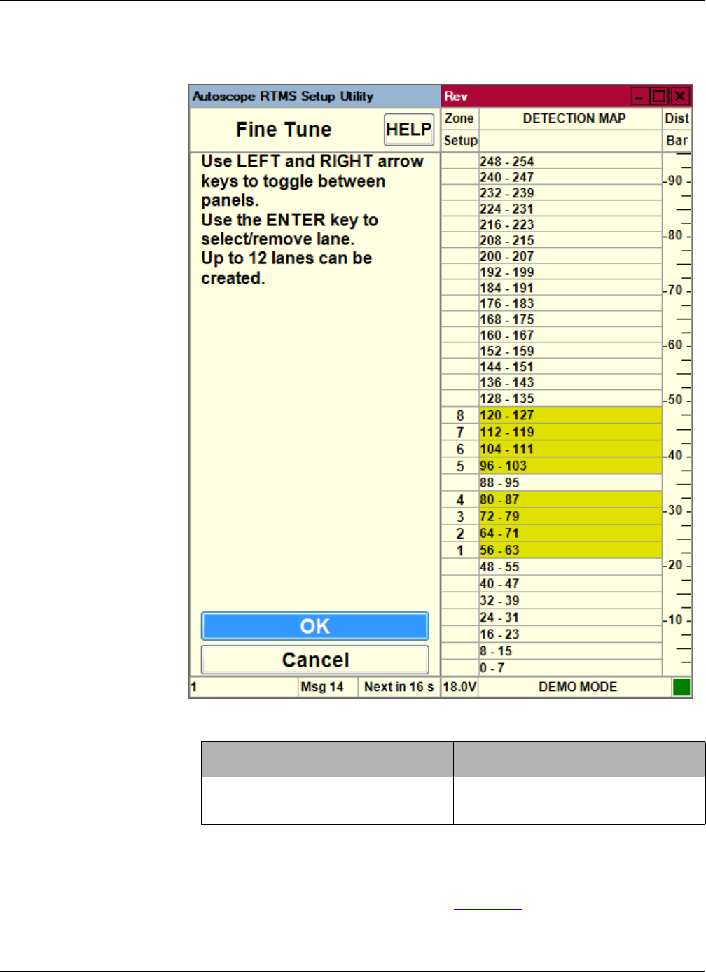
Chapter 5: Zone Setup
RTMS Sx-300 User Guide ©2014 Image Sensing Systems Inc. 5-54
The following screen appears.
6. Do you want to add or delete a zone?
7. Click OK.
The zone is added/deleted and you are returned to the Zone Setup screen.
8. To add or delete additional zones, repeat Steps 4 – 7.
Add Delete
In the right panel, click where you
want to add the zone.
In the right panel, click the number of
the zone to be deleted.
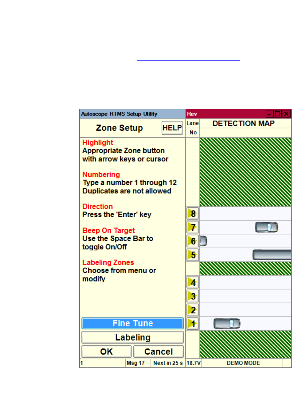
Chapter 5: Zone Setup
RTMS Sx-300 User Guide ©2014 Image Sensing Systems Inc. 5-55
Adjusting Zone Boundaries
This function is used to slightly move zone boundary positions. The minimum zone
width for Side-Fired Highway mode is five micro-slices. For Midblock Mode it is
seven micro-slices.
1. Start the utility (see “Starting the Setup Utility” on page 3-7).
2. On the Main Screen, click Manual Settings.
3. On the Manual Setup screen, click Zones.
The following screen appears.
4. Click Fine Tune.
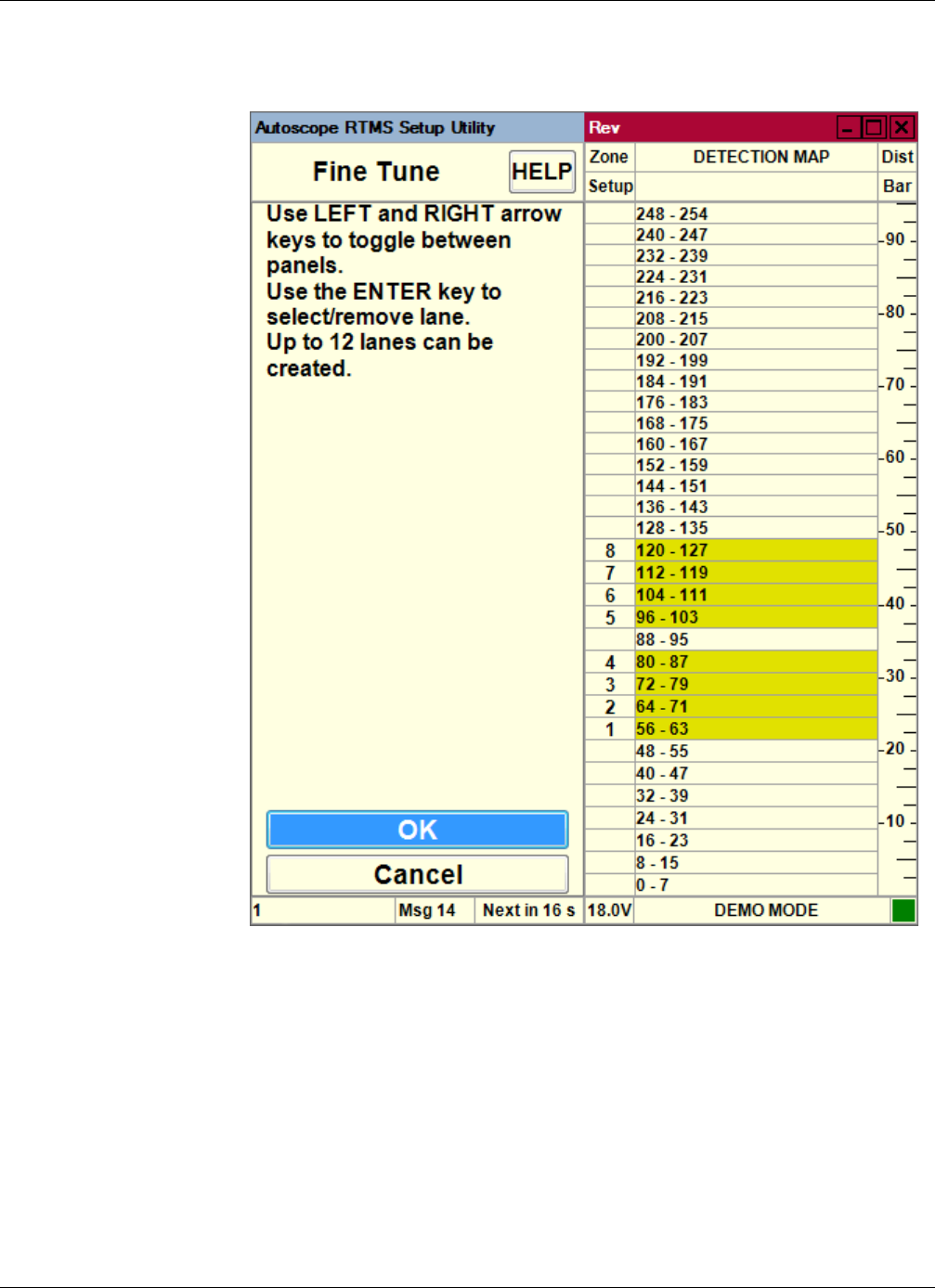
Chapter 5: Zone Setup
RTMS Sx-300 User Guide ©2014 Image Sensing Systems Inc. 5-56
The following screen appears.
5. Select the zone number that needs to be adjusted.
6. Use the up and down arrow keys to select the zone boundary.
7. To change the boundary by a single micro-slice at a time, click Move Away or
Move Closer.
Observe the effect on detection accuracy with the blips on the detection map. The
boundary move affects the zones on either side, reducing one and enlarging the
other.
– A counter shows the amount of shift at any time. This counter resets when
you select the next boundary.

Chapter 5: Zone Setup
RTMS Sx-300 User Guide ©2014 Image Sensing Systems Inc. 5-57
– By selecting Add/Remove Zone you can change the number of zones and
create wider zones spanning more than one lane.
– The same two mechanisms allow you to perform the entire zone setup
process manually, by adding zones and moving their boundaries.
8. To insert a space between zones, click Separate.
This feature can be used to separate lanes if barriers or raised lane dividers are
found on the road. Lane separation will further reduce “splashing” between lanes.
9. Repeat Steps 5 – 8 for each zone to be adjusted.
10. When finished, click OK.
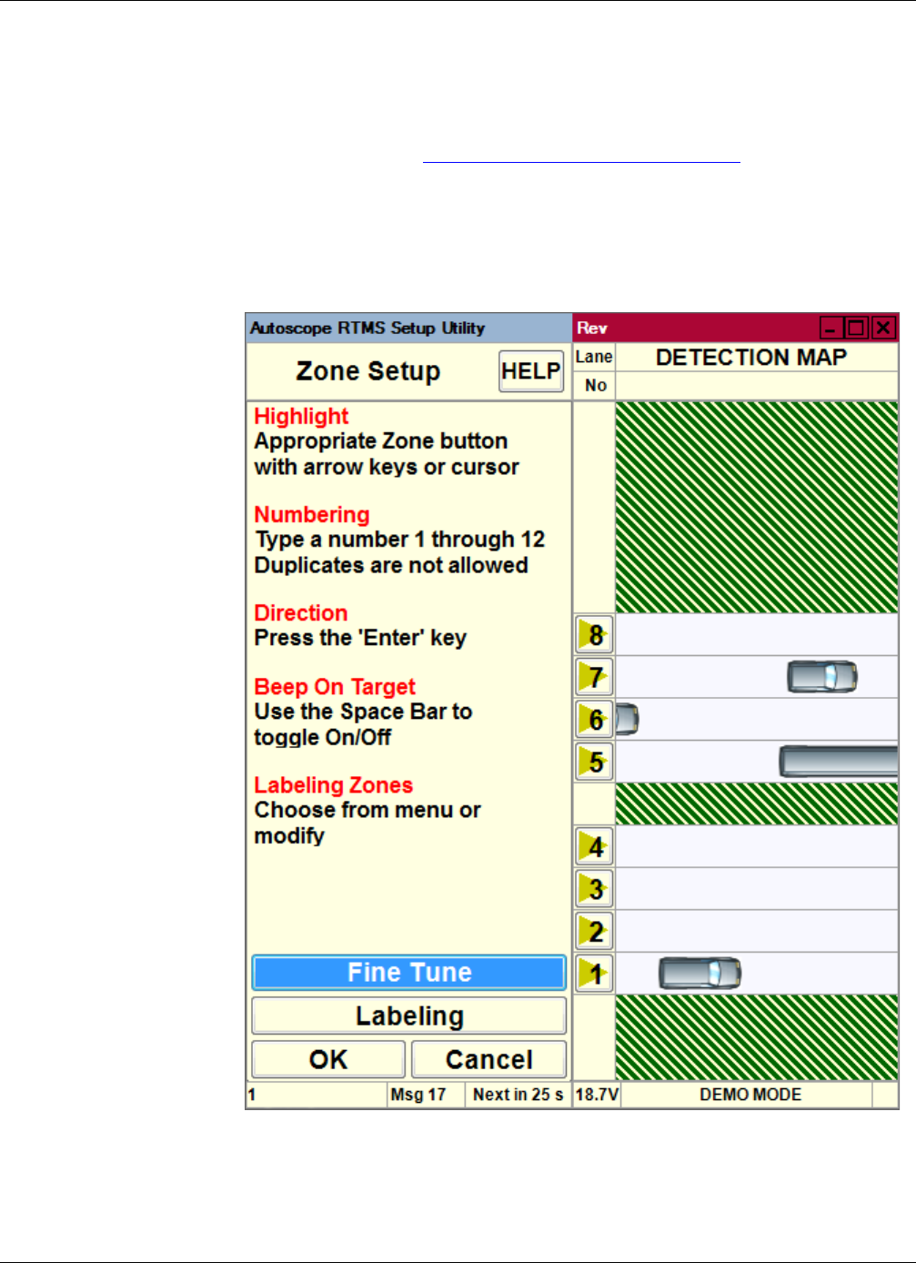
Chapter 5: Zone Setup
RTMS Sx-300 User Guide ©2014 Image Sensing Systems Inc. 5-58
Assigning Labels to Zones
This function is used to assign a meaningful name to a traffic lane (e.g.,
NORTHBOUND I69).
1. Start the utility (see “Starting the Setup Utility” on page 3-7).
2. On the Main Screen, click Manual Settings.
3. On the Manual Setup screen, click Zones.
The following screen appears.
4. Click Labeling.
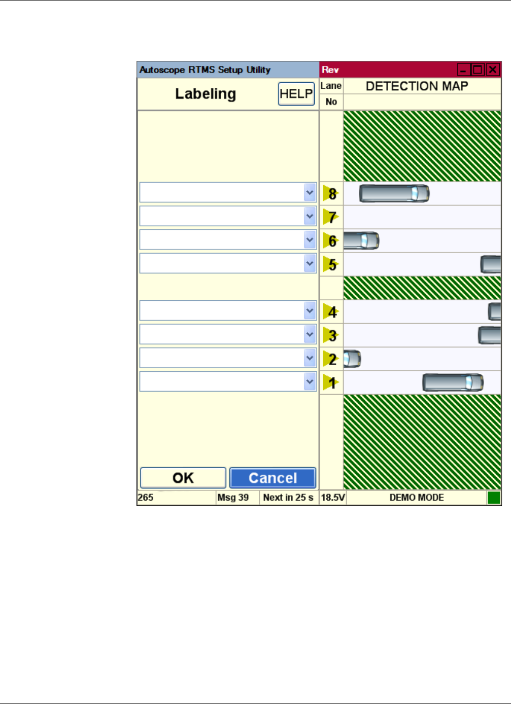
Chapter 5: Zone Setup
RTMS Sx-300 User Guide ©2014 Image Sensing Systems Inc. 5-59
The following screen appears.
5. Type or select a label for each lane.
The label can be up to 16 characters in length. Labels are stored in the Autoscope
RTMS Sx-300, but are not transmitted in the statistical data message.
6. After all lanes have been labeled, click OK.
You are returned to the Zone Setup screen.
7. To return to the Manual Setup screen, click OK.
8. To return to the Main Screen, click Exit.

RTMS Sx-300 User Guide ©2014 Image Sensing Systems Inc. 6-1
Chapter 6: Troubleshooting
General
Field troubleshooting of the Autoscope RTMS Sx-300 consists mainly of ensuring that
the unit is powered and communicating. Communication with the sensor in Normal
mode is confirmed by presence of the vehicles shown in the detection map and menu
buttons, and by the flashing of the indicator in the lower right corner of the screen,
denoting data transmission activity.
Messages
The following describe messages that may appear during Autoscope RTMS Sx-300
operations.
Message: Enabling ‘Per Vehicle’ data collection can significantly increase internal memory
usage when ‘Store Into Memory’ is enabled. Do you want to continue?
Description: This warning message indicates that selecting Per Vehicle ON when Store Into
Memory is already selected, will cause the internal memory of the Autoscope RTMS
Sx-300 sensor to fill up faster than when the Per Vehicle option is disabled (OFF).
Suggested Action: Click Ye s to set Per Vehicle ON, or No to cancel the operation.
Message: Enabling ‘Store Into Memory’ can significantly increase internal memory usage
when ‘Per Vehicle’ data collection is enabled. Do you want to continue?
Description: This warning message indicates that selecting Store Into Memory when Per Vehicle
ON is active, will cause the internal memory of the Autoscope RTMS Sx-300 sensor
to fill up faster than when Per Vehicle is disabled (OFF).
Suggested Action: Click Ye s to enable the Store Into Memory option, or No to cancel the operation.
Message: ‘Per Vehicle ON’ is active. Disabling ‘Store Into Memory’ will result in failing to
collect ‘Per Vehicle’ data. Do you want to continue?
Description: This warning message indicates that data collection for Per Vehicle cannot occur when
the Autoscope RTMS Sx-300 sensor is in Polled mode unless the Store Into Memory
option is selected.
Suggested Action: Do one of the following:
1. Click Ye s to disable the Store Into Memory option. There will be no Per Vehicle
data collected unless the mode is changed to STAT or Polled (see “Changing the
Data Mode” on page 5-2).
2. Click No to cancel the operation. Per Vehicle data will continue to be collected
and stored in the internal memory.

Chapter 6: Messages
RTMS Sx-300 User Guide ©2014 Image Sensing Systems Inc. 6-2
Message: ‘Per Vehicle ON’ is active. In order for ‘Per Vehicle’ data to be collected when in
Polled mode, the ‘Store Into Memory’ option should be selected.
Description: This warning message indicates that data collection for Per Vehicle cannot occur when
the Autoscope RTMS Sx-300 sensor is in Polled mode unless the Store Into Memory
option is selected.
Suggested Action: Click OK. Data collection for Per Vehicle is disabled. To enable data collection for
Per Vehicle, do one of the following.
1. Change the mode to STAT or Normal (see “Changing the Data Mode” on
page 5-2).
2. Turn on the Store Into Memory option (see “Defining Memory Options” on
page 5-25.
Message: The sensor you have selected is not compatible with this version of the setup
utility. Please install the G4 setup utility to configure this sensor.
Description: You attempted to configure an RTMS G4 sensor but the setup utility for this type of
sensor is not installed on your computer.
Suggested Action: Install the latest version of the setup utility for this type of sensor. For more
information, contact your sales or service representative.
Message: There is at least one port working in Polled mode. In order for ‘Per Vehicle’ data
to be collected, the ‘Store Into Memory’ option should be selected.
Description: This warning message indicates that data collection for Per Vehicle cannot occur when
the Autoscope RTMS Sx-300 sensor is in Polled mode unless the Store Into Memory
option is selected.
Suggested Action: Click OK. To not do data collection for Per Vehicle, select Per Vehicle OFF. To enable
data collection for Per Vehicle, do one of the following.
1. Change the mode to STAT or Normal (see “Changing the Data Mode” on
page 5-2).
2. Turn on the Store Into Memory option (see “Defining Memory Options” on
page 5-25).

Chapter 6: Symptoms
RTMS Sx-300 User Guide ©2014 Image Sensing Systems Inc. 6-3
Symptoms
The following outlines symptoms and suggested actions in troubleshooting power and
communication problems.
Symptom: Could not establish communications with the Autoscope RTMS Sx-300
Description: If you are unable to establish communications between an Autoscope RTMS Sx-300
unit and the Autoscope RTMS Setup Utility, the utility opens the Start screen to allow
you to direct a search for the Autoscope RTMS Sx-300. Possible causes are:
•Autoscope RTMS Sx-300 is not powered.
•Autoscope RTMS Sx-300 is not connected to the PC.
•Autoscope RTMS Sx-300 connection cable is faulty.
•COM port is being used by another program.
•Wrong COM port is selected.
•Communication to Autoscope RTMS Sx-300 is IP.
•Tx & Rx lines are crossed.
Suggested Action: Do the following in the order provided.
1. Check that:
•Autoscope RTMS Sx-300 is powered on.
•Autoscope RTMS Sx-300 is connected to the serial port of the laptop.
•No other program is using the COM port. Close down any other application
that is running on the laptop.
2. Try re-connecting (see “Defining Communications” on page 5-7).
3. Check the voltage:
a) Disconnect the DB9 cable from your computer.
b) Using a Voltmeter, measure the voltage between pins 2 and 5 of the connector.
It should read between 5 - 10 VDC.
c) If the voltage is not present, there could be a hardware fault.
4. If the problem persists, contact Technical Support.
Symptom: Download button on the Internal Memory screen is grayed out
Description: You have entered a date or time where:
•the date/ time is beyond the current date/time.
•the date/time in the From field is later than the date/time in the To field.
Suggested Action: Correct the date and/or time entries and retry the operation.

Chapter 6: Symptoms
RTMS Sx-300 User Guide ©2014 Image Sensing Systems Inc. 6-4
Symptom: Main screen shows target blips but no zone icons or parameters on buttons.
Description: Autoscope RTMS Sx-300 transmits and displays received data but Autoscope RTMS
Sx-300 has not received the READ command.
Suggested Action: Do the following.
1. Check cable to ensure continuity between MS connector pin T and COM port's
pin 3.
2. If the problem persists, contact Technical Support.
Symptom: Messages are no longer being stored into internal memory
Description: Internal memory is full and the FIFO check box on the Internal Memory screen is not
selected.
Suggested Action: To continue storing messages into internal memory do one of the following:
•Select the FIFO check box. Message will again be stored into internal
memory, but the oldest messages will be overwritten. See “Defining Memory
Options” on page 5-25.
•Erase the messages currently in memory. Once memory has been cleared, new
messages will be stored. See “Clearing Memory” on page 5-30.
Symptom: PC and sensor are communicating (Sensor settings are displayed on buttons) but
target “blips” are not shown on the main screen.
Description: Possible causes are:
•Autoscope RTMS Sx-300 is not in Normal mode.
•Unit is improperly aimed.
•Internal parameters corrupted.
•MW module fault.
Suggested Action: Do the following.
1. Ensure the unit is in the Normal mode.
2. Check sensitivity setting. See if targets appear when sensitivity is increased.
3. Cycle power to the unit and then edit parameters (mode, sensitivity, etc.).
4. Run Self-Test if the above is not successful.
5. Report findings to Technical Support.

Chapter 6: Symptoms
RTMS Sx-300 User Guide ©2014 Image Sensing Systems Inc. 6-5
Symptom: Autoscope RTMS Setup Utility will not start
Description: Microsoft .NET Framework 3.5 is not installed.
Suggested Action: Do the following.
1. Check that .NET Framework 3.5 is installed on the computer. If not, install it and
retry the operation.
2. If the problem persists, contact Technical Support.
Symptom: Selected firmware file is not compatible with this Autoscope RTMS Sx-300
hardware
(Firmware file version = x.x.x.x, Board version = y)
Description: The version of firmware you are trying to load is not supported on this version of the
hardware. This normally occurs when trying to load a version prior to 7.3.2.0 into a
sensor that only operates with 7.3.2.0 or above.
Suggested Action: Click OK. The operation is aborted.
Symptom: Timeout has expired and the main Communication Screen is displayed
Description: Possible causes are:
•Autoscope RTMS Sx-300 is not powered
•Timeout is not long enough
•Cable problem
Suggested Action: Do the following.
1. Check that the supply voltage is within limits at the source and at the MS
connector. Voltage outside the limits (too low or too high) will cause the power
supply to shut down.
2. Increase the timeout value by 2000 – 3000 ms, or longer depending on the type of
connection (see “Defining Communications” on page 5-7).
3. Check cable pin-out and continuity.
4. If the problem persists, contact Technical Support.
Symptom: You are trying to load setup to a different unit!
Do you want to continue?
Description: The setup file you are trying to upload to the Autoscope RTMS Sx-300 was created
for a different sensor. You should review the options to make sure everything is
appropriate for the sensor you want to upload to.
Suggested Action: Click Ye s to continue with the operation or No to cancel.

Chapter 6: Do’s and Don’ts
RTMS Sx-300 User Guide ©2014 Image Sensing Systems Inc. 6-6
Do’s and Don’ts
Table 6-1: Do’s and Don’ts
Do Don’t
Ensure setback is sufficient and height
is not over recommendations (see
“Height and Setback Requirements” on
page 2-5).
Attempt to mount a Side-fired
Autoscope RTMS Sx-300 closer than
1.5 m (5 ft) to the first monitored lane
without reviewing the following: “Zero
Setback” on page 2-5.
Use extension arms where needed to
improve sensor placement on exiting
structures.
Place Autoscope RTMS Sx-300 units
where overhead structures can interfere
with the microwave beam, e.g. under
overpass bridges and heavy structures.
Aim the Autoscope RTMS Sx-300
perpendicular to the lane direction.
Aim the Autoscope RTMS Sx-300 at an
angle exceeding five degrees from
perpendicular to the monitored lane.
Aim Autoscope RTMS Sx-300
according to the 1/3 rule, then verify
aiming interactively with the
Autoscope RTMS Setup Utility by
checking detection in all lanes.
Separate installation and aiming from
the setup stage.
Increase sensitivity to offset poor
aiming.
Pay attention to site cabling design.
Ensure serial port access is available for
set up. If necessary, add a pole-mounted
junction box.
Run the Autoscope RTMS Sx-300
cable directly to cabinets out of visual
range of the sensor’s detection
footprint.
When powering with low voltage input
AC transformer, design for 16 VAC.
Specify use of Controllers in new
applications requiring data only.
Evaluate power arrangements vs.
distance. Use 1. Heavy gauge power
wires to reduce voltage drop, or
2. Higher supply voltage.
Use thin power wires with low voltage
supply.
Attempt connecting wires thicker than
#18 with the Autoscope RTMS Sx-300
MS connector.
Use wireless communication for:
•Long distances, to offset trenching
cost.
•Quick deployment and portability.
Specify dial-up communication in
applications requiring real time data. It
is applicable to infrequent downloads
of traffic counting data.

Chapter 6: Technical Support
RTMS Sx-300 User Guide ©2014 Image Sensing Systems Inc. 6-7
Technical Support
If you cannot correct the problem, do the following before contacting Technical
Support:
•Return to the beginning of the entire installation process and review the steps.
Be sure that you followed all of the instructions provided.
•If you reviewed the installation instructions and you are still encountering a
problem, document:
– What is happening. Example: Unable to set up networking.
– When the problem started. Example: During software installation.
– Any error messages that were shown including the exact words and any
numbers in the message.
•If possible, have another person try the installation to the stage where you
encountered problems.
•If the attempts to correct the problem fail, call Technical Support.
North American Users’ Resource
North and South American customers call Econolite Control Products, Inc. at:
Toll Free: 1.800.225.6480
Main telephone: 1.714.630.3700
Fax questions to: 1.714.630.6349
All Other Users’ Resources
Customers outside Northern and Southern America may call Image Sensing Systems,
Inc. headquarters at:
Main telephone: 651.603.7700
Fax questions to: 651.305.6402
Or contact one of our international offices:
ISS Europe Ltd.
Phone: +44.1707.378870
Fax: +44.1707.378875
City Park
Swiftfields
Welwyn Garden City
Hertfordshire AL7 1LY United Kingdom
ISS AsiaPac
Phone: +852.2827.1123
Fax: +852.2827.0056
Suite 1513, 15th Floor, Chevalier Centre
No. 8 Wang Hoi Road
Kowloon Bay, Hong Kong

RTMS Sx-300 User Guide ©2014 Image Sensing Systems Inc. A-1
Appendix A: Cabling and Connectors
General
Autoscope RTMS Sx-300 units use a single 32-pin MS connector for power and
communications. For information about the MS pinouts, see “MS Connector Pin Out”
on page A-3.
The Autoscope RTMS Sx-300 cable should be made from 20 or 22 gauge stranded
wire arranged in twisted pairs.
Cables exposed to outdoor conditions should be UV shielded.
The number of pairs required depends on the RTMS Sx-300 model.
Table A-1: Required Wiring Pairs
Model Number of Pairs
RTMS Sx-300 (Base Unit) Standard RS-232/485 plus power: three pair
If using RTS/CTS option for RS-232: four pair
If using RS-485: four pair
RTMS Sx-300 TCP (Base Unit plus TCP/IP) Two additional pair
RTMS Sx-300-SSP (Base RTMS Unit plus
Second Serial Port)
If using without RTS/CTS option for RS-232: one additional
pair
If using RTS/CTS option for RS-232: two additional pair
If using RS-485: two additional pair
Contact Closures: The Sx-300 SSP model has
built in Contact Closures. If you are utilizing
them you will need:
Eight additional pair. Note, Up to eight additional only if all
Contact Closures are used.

Preparing a Cable
RTMS Sx-300 User Guide ©2014 Image Sensing Systems Inc. A-2
Preparing a Cable
Use cable such as the Belden number 951x (1x indicates number of pairs). For
example: 9516 is a 6-pair cable. In preparing a cable note the following:
•Use the Connector Kit from ISS to match the product:
– For Sx-300 base system use RTMS CNSET RS232 per ISS Part Number
A750-1146
– For Sx-300 TCP use RTMS CNSET RJ45 per ISS Part Number
A750-1153
– For Sx-300 SSP use RTMS CNSET RS232 per ISS Part Number
A750-1149
– For Sx-300 SSP-CC use RTMS CNSET RS232 per ISS Part Number
•Decide whether or not to install extra cable pairs for growth purposes.
•The crimp pins are designed for stranded wire only.
•Do not use cable employing solid wires.
•The Daniels Manufacturing Corporation crimping tool M22520/1-01 AF8
with head number M22520/1-02 or equivalent is recommended.
•Do not solder MS connector pins to the cable. They must be properly
crimped.
The following table lists the maximum length of the cable based on the type.
Table A-2: Max Cable Length
Protocol Max Cable Length
RS-232 For baud rate of 19,200 or 115,200: 15 m (50 ft)
For baud rate of 9600: 152 m (500 ft) is the recommended
maximum. However, you can go up to 244 m (800 ft) when
the:
•Cable has a minimum gauge of 20 AWG
•Baud rate is 9600
•Environment is ideal
•Cable is continuous
RS-485/RS-422 1219 m (4000 ft) for all baud rates.
TCP/IP over CAT 5 91 m (300 ft)

Connecting a Cable to the Autoscope RTMS Sx-300
RTMS Sx-300 User Guide ©2014 Image Sensing Systems Inc. A-3
Connecting a Cable to the Autoscope RTMS Sx-300
To connect a cable to the Autoscope RTMS Sx-300 device, do the following.
1. Thread the cable through the backshell before inserting pins into shell.
2. Use the insertion tool (red) to insert wires with crimped pin into shell.
3. Use the extraction tool (white) to remove a crimped wire to correct an error.
4. Access to the serial connection should be available within view of the monitored
lanes.
•For example: inside an access panel or cabinet on the pole.
•Verifying the sensor's calibration is easy when the user sees the Autoscope
RTMS Sx-300 data together with manual counts.
Surge Suppression/Protection
Each Autoscope RTMS Sx-300 unit has built-in surge-suppression hardware. For
complete information see Appendix B: “Surge Protection”
Wiring Notes
The DB9 connectors and terminal blocks serve as a disconnect point, which allows
disconnecting the Autoscope RTMS Sx-300 from the transmission line for direct
connection to the laptop's COM port for setup.
Terminating resistors (100-120 ohms) are required at the extreme ends of the Receive
and Transmit transmission pairs.
Transmit and receive pairs must be transposed when connecting to a DTE (PC, Data
processing System). To interface with a PC an RS-485/232 converter may be required
as PCs typically do not have RS-485 interfaces.
RS-485/232 converter connector type and pin assignment are not shown as these are
not standardized and vary between models.
MS Connector Pin Out
Pin labeling in Figure A-1 is a guideline only. Verify pin location on actual connector
before inserting wire.
NOTES:
•The Autoscope RTMS Sx-300 unit can be configured for a variety of
communication options. It is important to know which options are included
with your unit prior to preparing cables. MS connector pins cannot be shared.
Take note of the individual wiring instructions provided in this manual.
•Connect the cable’s shield (drain wire) to pin U at the MS connector.
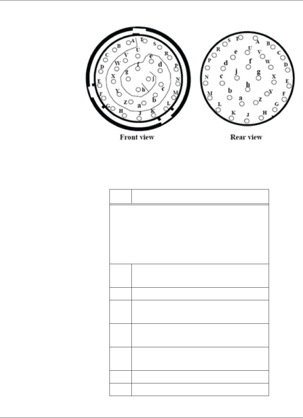
MS Connector Pin Out
RTMS Sx-300 User Guide ©2014 Image Sensing Systems Inc. A-4
Figure A-1: MS Connector
Table A-3: Cable Pair Requirements
Pin # Function
NOTE: Pins A- S are used only for Contact Closure.
Pins W, Z, d and e are only used for secondary
communication options. For information on
cable pair requirements for theses pins, see the
appropriate chapters in the Autoscope RTMS
Sx-300 Optional Configurations User Guide
(PN A900-1155-2).
T Rx (Serial Port RS-232)
Rx- (Serial Port RS-485)
U Ground (all Serial Ports and Contact Closures)
V Tx (Serial Port RS-232)
Tx- (Serial Port RS-485)
X CTS (Serial Port RS-232)
Tx+ (Serial Port RS-485)
Y RTS (Serial Port RS-232)
Rx+ (Serial Port RS-485)
f, g Low voltage power 12-24 VAC or DC
h, j Reserved
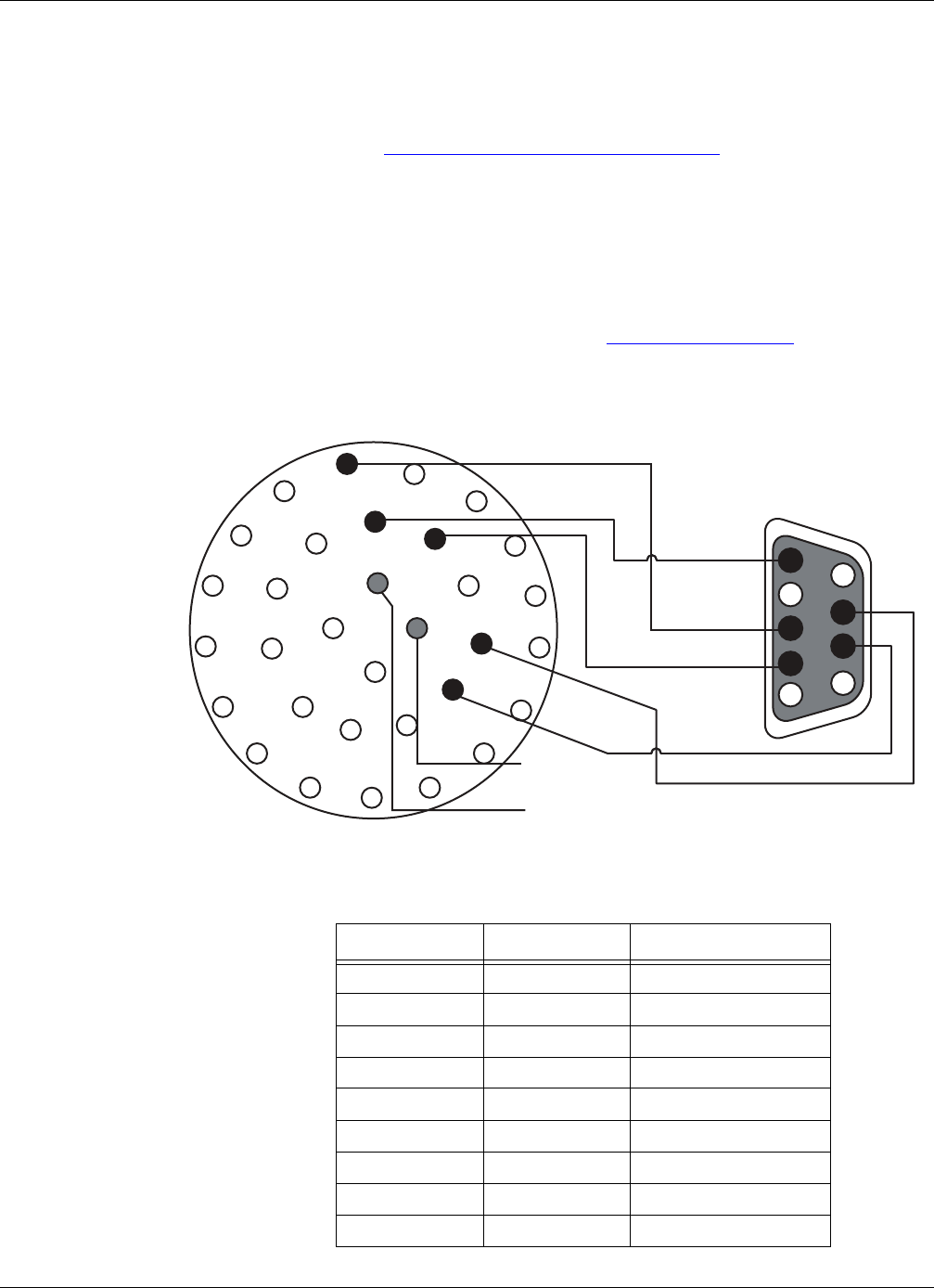
Standard Serial Port
RTMS Sx-300 User Guide ©2014 Image Sensing Systems Inc. A-5
Standard Serial Port
The Autoscope RTMS Sx-300 comes with a Serial Port that can be configured as
RS-232 or RS-485. For information about how to set the communications
configuration, see “Defining Communications” on page 5-7.
Standard RS-232 Port Wiring
The standard Autoscope RTMS Sx-300 RS-232 port wiring consists of Transmit (Tx),
Receive (Rx), Request to Send (RTS), Clear to Send (CTS) and Ground lines wired to
the MS pins respectively. The use of a female DB9 connector and wiring shown
allows the use of standard serial cable for direct connection to the PC for setup
purposes. For the maximum cable length, see Table A-2 on page A-2). Rear views of
connectors are shown to assist in cable preparation. The Autoscope RTMS Sx-300 is
configured as a Data Communications Equipment (DCE) device.
Figure A-2: RS-232 Wiring Diagram
1
4
6
9
2
3
7
5
8
A
B
C
D
E
F
G
H
J
K
L
M
N
P
R
ST
U
V
W
X
Y
Z
a
b
c
d
e
f
g
h
j
MS Connector
Rear View
DB-9 Female
Rear View
Power
12-24V
AC/DC
SGND
Rx
RTS (optional)
Tx
CTS (optional)
Table A-4: RS-232 Wiring Matrix
DB9 Pin Signal MS Connector Pin
1NC N/A
2Tx V
3Rx T
4NC N/A
5SGnd U
6NC N/A
7RTS Y
8CTS X
9NC N/A
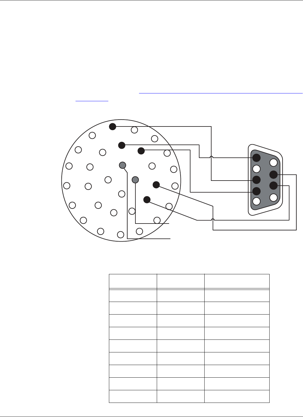
RS-485 Port Wiring
RTMS Sx-300 User Guide ©2014 Image Sensing Systems Inc. A-6
RS-485 Port Wiring
There is no standard pin configuration for RS-485 on a DB9 connector.; so we suggest
the following configuration. The wiring diagram shown will connect directly to a
RS-232 configured DB9 without the need for an RS-232/RS-485 converter. The
maximum cable length is 1219 m (4000 ft). Over short distances (9 m [30 ft]) the
wiring diagram shown below is compatible with an RS-232 port.
A disconnect point is recommended to allow the Autoscope RTMS Sx-300 to be
detached from the transmission line without disruption of communications with other
sensors on the line. See “Connecting Autoscope RTMS Sx-300 to External Modems”
on page A-7 for details.
Figure A-3: RS-485 Wiring Diagram
1
4
6
9
2
3
7
5
8
A
B
C
D
E
F
G
H
J
K
L
M
N
P
R
ST
U
V
W
X
Y
Z
a
b
c
d
e
f
g
h
j
MS Connector
Rear View
DB-9 Female
Rear View
Power
12-24V
AC/DC
SGND
Rx–
Rx+
Tx–
Tx+
Table A-5: RS-485 Wiring Matrix
DB9 Pin Signal MS Connector Pin
1NC N/A
2Tx- V
3Rx- T
4NC N/A
5SGnd U
6NC N/A
7Rx+ Y
8Tx+ X
9NC N/A
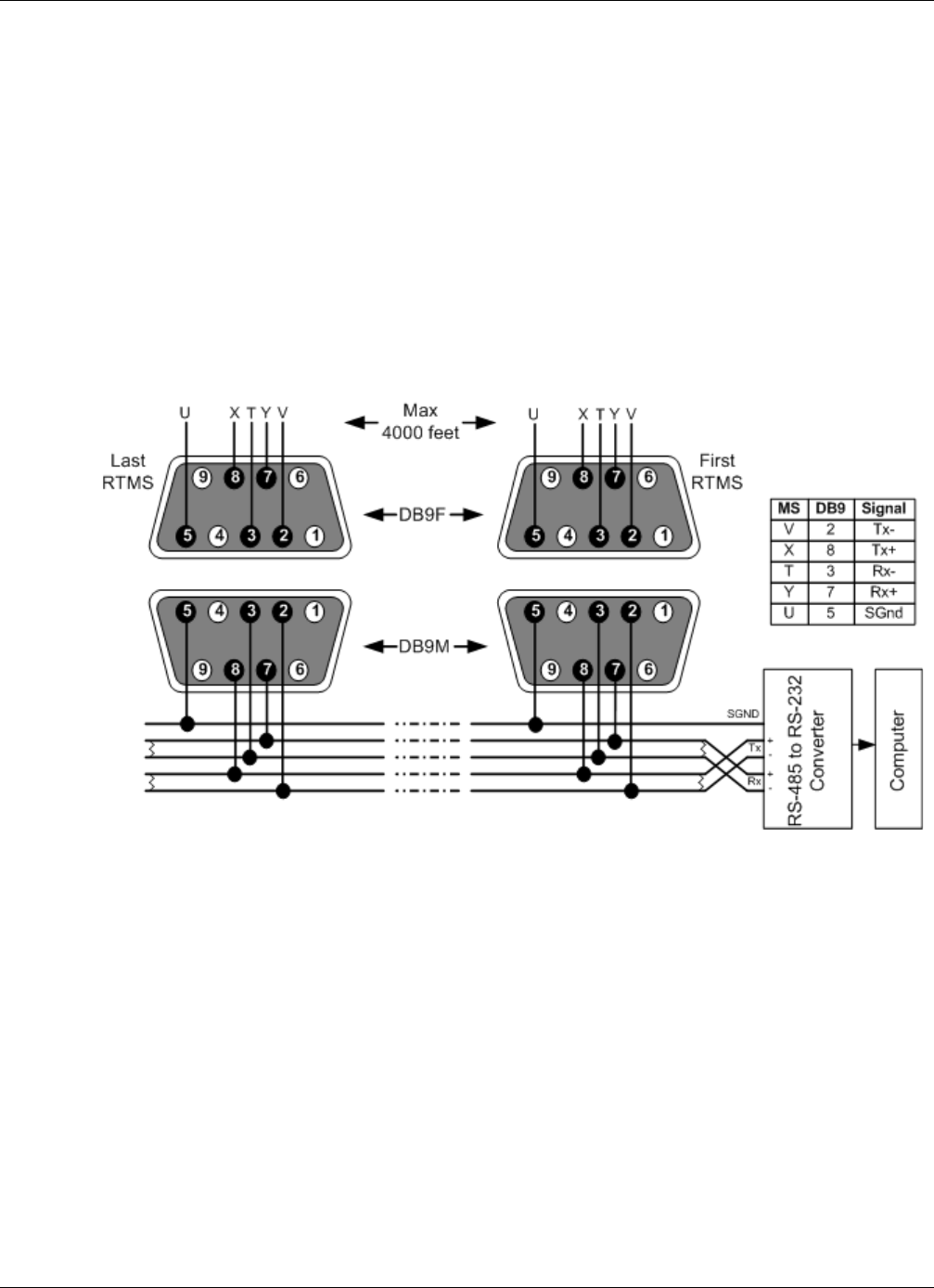
RS-485 Multi-Drop Wiring
RTMS Sx-300 User Guide ©2014 Image Sensing Systems Inc. A-7
RS-485 Multi-Drop Wiring
The RS-485 setting of the Autoscope RTMS Sx-300 Serial Port allows up to 32
Autoscope RTMS Sx-300 units to be employed on the same serial bus over distances
up to 1219 m (4000 ft).
RS-485 is used for multipoint communications. This allows more devices to be
connected to a single cable, similar to an Ethernet network which uses a coaxial cable.
Most RS-485 use a Master/Slave architecture, where each slave unit has its own
unique address and responds only to packets addressed to it. The packets are generated
by a master (e.g., PC) which periodically polls all connected slave units.
The following diagram shows the use of a 4-Wire line. Note, a 2-wire line is not
recommended or supported.
Figure A-4: RS-485 Multi-Drop Wiring
Connecting Autoscope RTMS Sx-300 to External Modems
The Autoscope RTMS Sx-300 may be connected to a remote traffic data collection
system over private telephone lines using modems. Multiple Autoscope RTMS
Sx-300 units connecting to remote systems, including the Cluster Hub or NEWS Hub
systems must be placed in Polled mode and may require the use of modems.
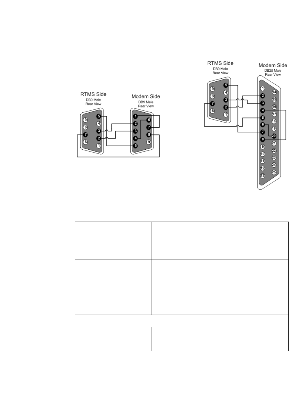
Connecting Autoscope RTMS Sx-300 to External Modems
RTMS Sx-300 User Guide ©2014 Image Sensing Systems Inc. A-8
Modem Cables
A cable connecting the Autoscope RTMS Sx-300 RS-232 port to the modem's RS-232
port must provide a Male connectors at both ends (null cable) and the cable must
operate within the parameters provided below. A modem's RS-232 ports will usually
employ DB9 or DB25 connectors.
Figure A-5: Autoscope RTMS Sx-300-To-Modem Connections
Table A-6: Modem Cabling
Function
From
Autoscope
RTMS Sx-300
DB9
To Modem
DB9
To Modem
DB25
Transpose Tx and Rx Pin 2 Pin 3 Pin 2
Pin 3Pin 2Pin 3
Connect ground Pin 5 Pin 5 Pin 7
RTS to Autoscope RTMS
Sx-300
Pin 7Pin 8Pin 5
Modem Side Control Looping
DCD to CTS Pin 1 to Pin 7 Pin 4 to Pin 8
DSR to DTR Pin 4 to Pin 6 Pin 6 to Pin 20
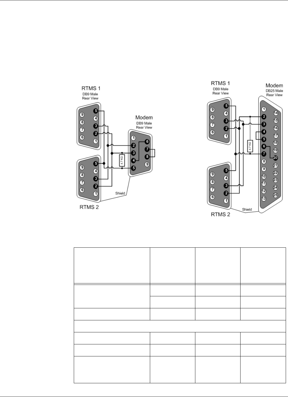
Connecting Autoscope RTMS Sx-300 to External Modems
RTMS Sx-300 User Guide ©2014 Image Sensing Systems Inc. A-9
Modem Sharing
Autoscope RTMS Sx-300 units located in close proximity may connect to a single
modem. A modem sharing cable will have “Y” construction and will consist of one
DB-9M connector per Autoscope RTMS Sx-300, and one DB-9M or DB-25M
connector at the modem (as shown below).
Modem side strapping provides required flow control functions, not provided by the
standard Autoscope RTMS Sx-300 RS-232 port.
Figure A-6: Modem sharing “Y” cables. (No Memory Download.)
Table A-7: Modem Sharing “Y” Cabling
Connection/Function
From
Autoscope
RTMS Sx-300
DB9
To M od em
DB9
To M od em
DB25
Transpose Tx and Rx Pin 2 Pin 3 Pin 2
Pin 3Pin 2Pin 3
Connect ground Pin 5 Pin 5 Pin 7
Modem Side Strapping
RTS to CTS Pin 1 to Pin 7 Pin 4 to Pin 8
DSR to DTR Pin 4 to Pin 6 Pin 6 to Pin 20
Connect a 4.7 kΩ resistor
from Tx to ground to
prevent noise.
Pin 3 to Pin 5 Pin 2 to Pin 7
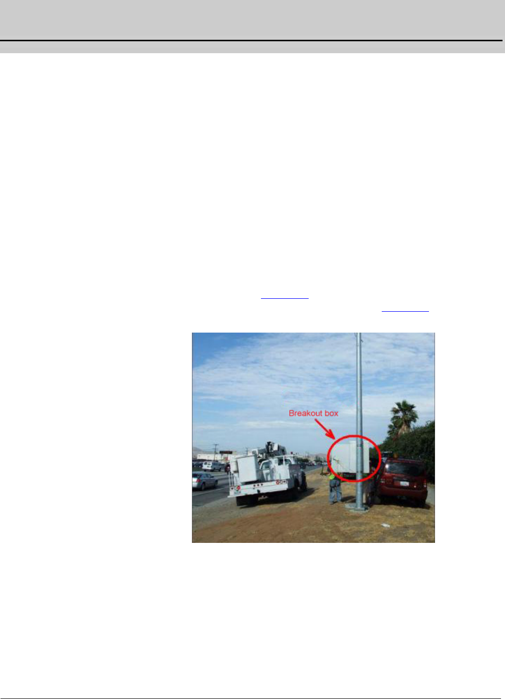
RTMS Sx-300 User Guide ©2014 Image Sensing Systems Inc. B-1
Appendix B: Surge Protection
General
Autoscope RTMS Sx-300 sensors are deployed in locations where the quality of
power lines can be questionable. Industrial machinery and environmental factors can
cause excess noise and voltage/current spikes on power lines. Additionally, poor
grounding of equipment can amplify the effects of these disturbances. It is
recommended that all lines connected to the Autoscope RTMS Sx-300 sensor (i.e.,
power and communication) have surge protection and each sensor be sufficiently
grounded as outlined in this appendix.
The purpose of this appendix is to provide an understanding of why proper grounding
and surge protection is important to a successful Autoscope RTMS Sx-300 sensor
deployment and provide guidelines for grounding of equipment and installing surge
protection devices to protect each Autoscope RTMS Sx-300 sensor.
Breakout Boxes
Every sensor should have a breakout box on the same pole that the Autoscope RTMS
Sx-300 sensor is mounted (see Figure B-1). The breakout box should be no more than
6 m (20 ft) from the Autoscope RTMS Sx-300 sensor (see Figure B-1).
Figure B-1: Typical Installation
Each breakout box should contain a manufacturers approved surge suppression
package, which includes a power supply and all the necessary surge protection
devices.
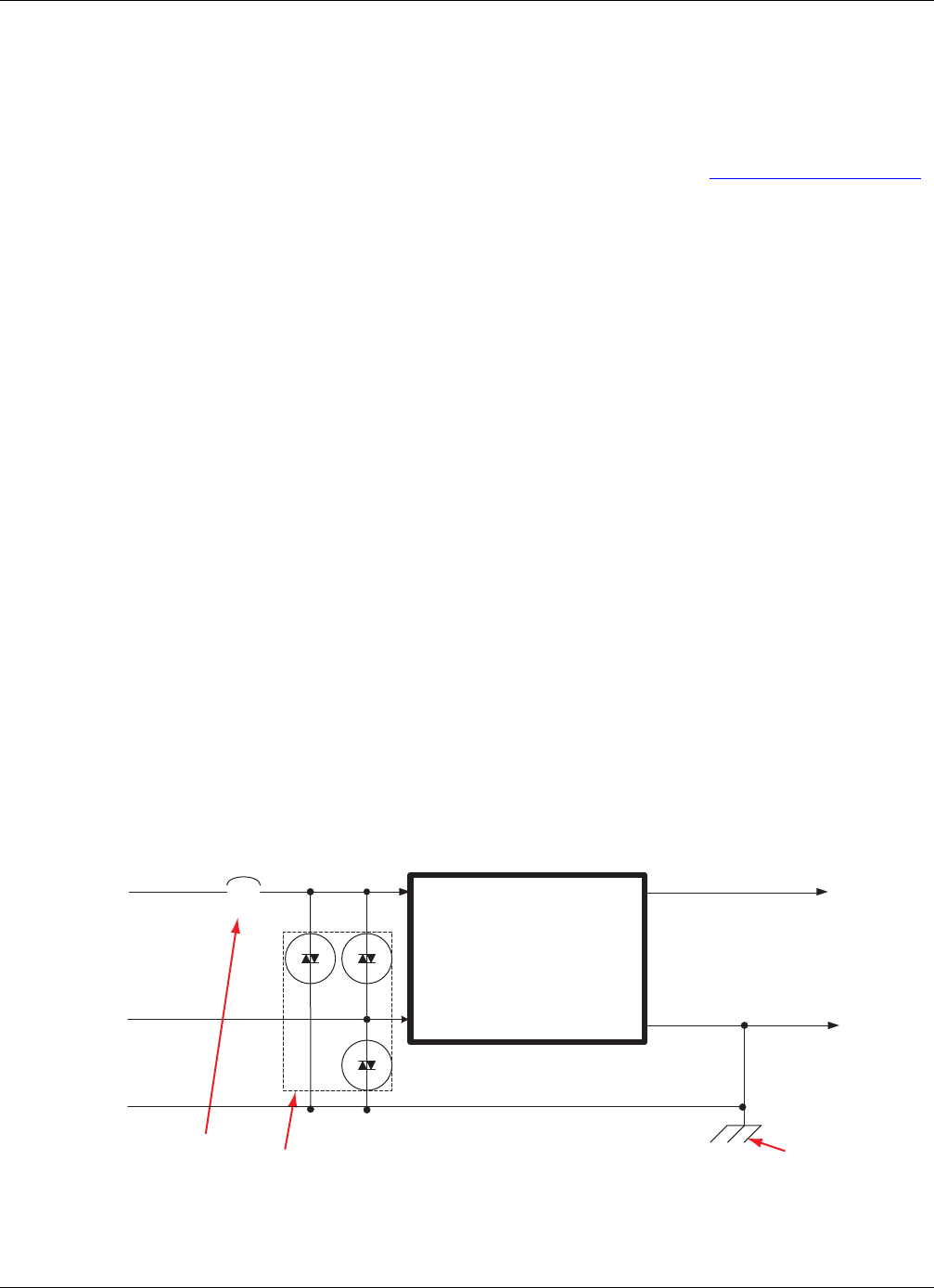
Parts of the Surge Suppression Package
RTMS Sx-300 User Guide ©2014 Image Sensing Systems Inc. B-2
Cabling to the Breakout Box
The Mains power should enter the breakout box and go directly to the surge protection
package as described in the wiring diagram provided with the package. The earth
ground wire from the Mains power should tie to the breakout box, the surge protection
package, and directly to the grounding rod as described in “Grounding” on page B-5.
IMPORTANT: The Mains earth ground conductor MUST come with the Mains
power conductors from the utility. The local ground rod is only for
suppression of surge and must be tied to the earth ground reference
from the power source.
Cabling From the Breakout Box
The only cable leaving the breakout box should be the low voltage power cable going
directly to the sensor.
IMPORTANT: The cable from the breakout box to the Autoscope RTMS Sx-300
sensor should be routed up the pole directly to the sensor and should
not share conduits with or be routed next to high voltage/high
current (AC or DC) power lines.
Parts of the Surge Suppression Package
Power Line Protection
The first part of a surge suppression package is providing a barrier between the
incoming power lines and the power provided to the Autoscope RTMS Sx-300 sensor.
A circuit breaker (CB) and a power transient suppressor (PTS) provide this protection.
The incoming power line should go through the circuit breaker, then to the PTS
device. In this configuration, if a surge occurs the PTS will shunt excessive current to
earth ground and subsequently trigger the CB. This opens the circuit and prevents
damage to the sensor and the PTS. The CB must have a 2A rating.
Figure B-2: Power Lines Protection
+
CB
Line
Neutral
Ground
Earth ground
Power transient suppressor
Circuit breaker
AC Mains
To RTMS
power
terminals
Power Supply
110VAC/12-24VDC
–
{
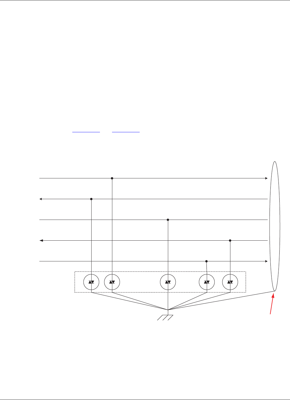
Parts of the Surge Suppression Package
RTMS Sx-300 User Guide ©2014 Image Sensing Systems Inc. B-3
IMPORTANT: The negative terminal of the low voltage side of the power supply,
battery, or solar controller must be connected to the earth ground in
order to provide a reference point for the Autoscope RTMS Sx-300
built-in surge protection.
Communication Line Protection
Communication lines to the Autoscope RTMS Sx-300 sensor are sensitive lines that
must be protected from external influences to prevent damage to the communication
interface on the sensor and ensure uncorrupted data flow to and from the sensor. Each
communication line should be protected by a device that will shunt excess current on
the line to earth ground rather than sending that current through the Autoscope RTMS
Sx-300 sensor and causing damage to the device. Care must be taken when providing
protection on communication lines to ensure the device chosen will not add excess
capacitance or inductance that could cause disruptions to the integrity of the data.
Figure B-3 and Figure B-4 show the protections provided by the manufacturers
approved surge suppression packages on the communications interfaces for the
Autoscope RTMS Sx-300 sensor.
Figure B-3: Serial Port Protection
TxD
RxD
SGND
RTS
CTS
Cable’s shield (drain wire)
Serial Transient
Suppression
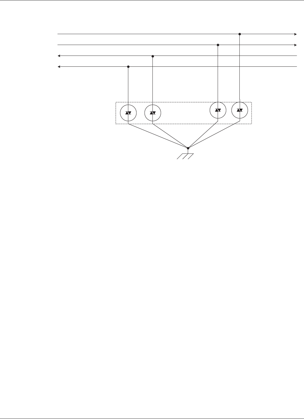
Parts of the Surge Suppression Package
RTMS Sx-300 User Guide ©2014 Image Sensing Systems Inc. B-4
Figure B-4: Ethernet Port Protection
TX+
TX–
RX+
RX–
Ethernet Transient
Suppression

Grounding
RTMS Sx-300 User Guide ©2014 Image Sensing Systems Inc. B-5
Grounding
Providing a Proper Ground
Providing a low resistance earth ground connection is essential to achieving effective
surge protection. Total resistance from the protected circuit to the earth should be <5
ohms.
Figure B-5: Earth Ground Connection
A grounding rod (see Figure B-5) should be at least 1.83 m (6 ft) in length and placed
as close as possible to the base of the Autoscope RTMS Sx-300 mounting pole. The
grounding conductor should be flexible copper braid or copper wire 12AWG or larger.
Grounding conductor
6 foot copper rod

Grounding
RTMS Sx-300 User Guide ©2014 Image Sensing Systems Inc. B-6
Why Grounding is Important
Figure B-6: Surge Channeled into Earth Ground
The earth grounding rod, together with proper ground of the breakout box, and surge
protecting devices installed in close proximity of the mounting pole, create a barrier or
‘sink hole’ for any charges and surges coming towards the sensor from the
surrounding area (see Figure B-6). These charges and surges may be caused by
industrial noise, power surges, or lightning.
Thunderstorm lightning is in its own class of destructive forces to sensors. Typically, it
can generate 30 to 300 kA of current, far beyond the capabilities of any surge
protecting devices. Therefore, a direct or near direct lightning hit may cause
equipment damage even in the presence of surge/transient protecting devices.
Because lightning is a major influence on power line surge, it is important to
understand the exposure to thunderstorms in the area where the Autoscope RTMS Sx-
300 sensor is being installed. In areas that are exposed to large number of
thunderstorms, protecting sensors will be more challenging.
Power and comm lines
Surge induced into lines Lightening discharge
Earth grounding rod
Mounting pole, sensor
and breakout box

Low Voltage Power
RTMS Sx-300 User Guide ©2014 Image Sensing Systems Inc. B-7
Low Voltage Power
The manufacturers approved surge suppression packages include a 24VDC power
supply. The output of this supply is tied to the cable that powers the Autoscope RTMS
Sx-300 sensor. This cable should not be longer than 6 m (20 ft) in length and should
only be run directly from the breakout box at the mounting pole for each Autoscope
RTMS Sx-300 sensor up the mounting pole to the Autoscope RTMS Sx-300 sensor.
IMPORTANT: The cable from the breakout box to the Autoscope RTMS Sx-300
sensor should be routed up the pole directly to the sensor and should
not share conduits with or be routed next to high voltage/high
current (AC or DC) power lines.
You should not power Autoscope RTMS Sx-300 sensors from low voltage sources
(either AC or DC) over cables longer than 6 m (20 ft) for the following reasons:
•Long low voltage lines act as an antenna for all sorts of disturbances, noise,
and surges.
•Significant power loses can occur at long distances.
•305 m (1000 ft) of typical 18 AWG stranded wire introduces resistance of
about 6.6Ω per wire. The base Autoscope RTMS Sx-300 unit draws 0.25A at
12V. The cable loss can be calculated as:
Vdevice = IRTMS * Rcable = 0.25A * (2 * 6.6Ω) = 3.3 VDC
Note:
Rcable = 2 * resistance per wire because the current travels to the device on the
power wire and returns from the device on the ground wire.
With a cable input voltage of 12 VDC and a 3.3V cable loss, the voltage at the
Autoscope RTMS Sx-300 input will be 8.7V.
This is less than the minimum voltage requirement of the Autoscope RTMS
Sx-300 sensor (12V).
The manufacturer cannot guarantee proper operation of the unit and/or its longevity if
low voltage power over a long line is used to power an Autoscope RTMS Sx-300
sensor, and does not recommend or support providing power in this configuration.
However, the following are some things to help limit the risks.
•Use an isolated 24VDC power source.
•Increase the gauge of the power wires to reduce voltage drop. Reference the
datasheet for the wire you are installing or an American Wire Gauge lookup
table for resistance per foot of each wire gauge.
•Mount low voltage surge protection at the base of the mounting pole and
ensure the protection device has a low resistance reference (<5 ohms) to earth
ground.
•Avoid running Autoscope RTMS Sx-300 sensor cables parallel or close to
high voltage/high current power lines (including in conduits).

Autoscope RTMS Sx-300 Interface Panels
RTMS Sx-300 User Guide ©2014 Image Sensing Systems Inc. B-8
Autoscope RTMS Sx-300 Interface Panels
It is recommended that approved interface panels, which include appropriate surge
protection, be used to protect Autoscope RTMS Sx-300 sensors. The approved
interface panels, which include appropriate surge protection, are listed in Table B-8.
The connections for each surge panel is shown in the pages that follow.
Table B-8: Autoscope RTMS Sx-300 Interface Panel Part Numbers
Description Part
Number
DIN Rail Power and RS-232 Interface Panel A600-1099
DIN Rail Power and RS-232 and RS-422/485Interface Panel A600-1098
DIN Rail Power and RS-232 and TCP/IP Interface Panel A600-1097
DIN Rail Power and RS-485 Interface Panel A600-1100
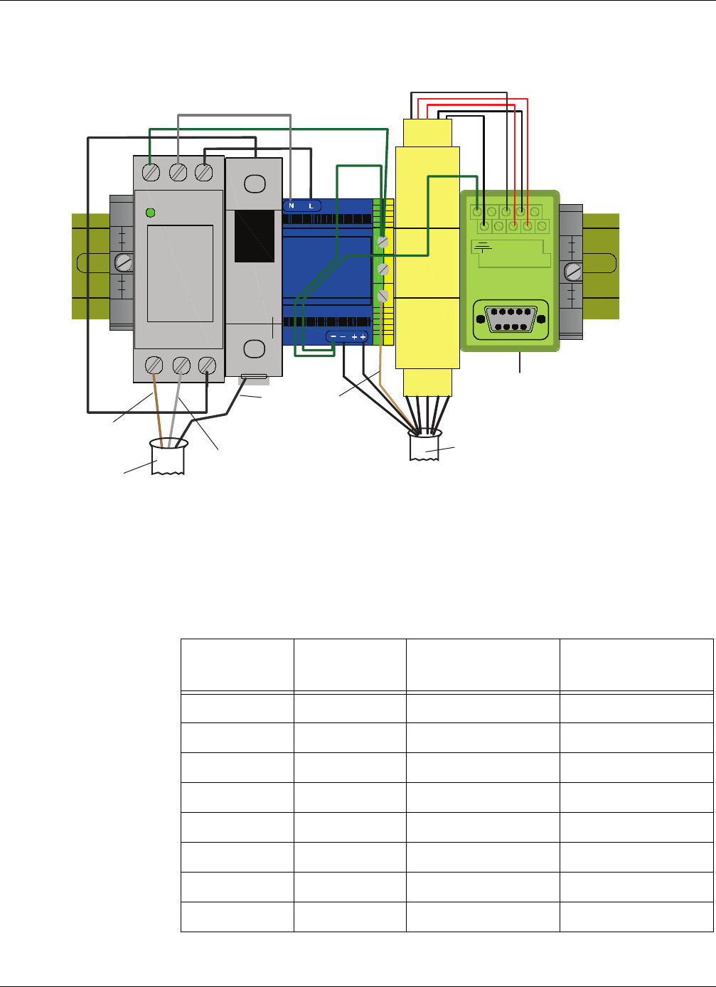
Autoscope RTMS Sx-300 Interface Panels
RTMS Sx-300 User Guide ©2014 Image Sensing Systems Inc. B-9
DIN Rail Power and RS-232 Interface Panel (P/N A600-1099)
Figure B-7: Power and RS-232 Interface Panel Wiring
RS-232 DB9 Female Connector
(to PC or TMC comm link)
MTL
1 2 3 4 5
1 2 3 4 5
UNPROTECTED
PROTECTED
DSP60 24
DCPwr
0V
GNL
UNPROTECTED
POWER /
PROTECTED
GNL
12345
6789
Note, must provide earth ground
conductor from utility.
Backplate/DIN rail must
be connected to earth
ground at install time.
NOTE:
110 VAC
Power
Protect Ckt Bkr
(2 Amp)
24 VDC
Power RS-232
Protection
Hot
Neutral MS Cable
Ground
110 VAC Power Cable
Shield
Table B-9: MS Cable Wiring for Power and RS-232 Interface Panel
MS Cable Pin RS-232
Protect Pin 24 VDC Power Pin Signal Name
g N/A – DC GND
f N/A + +24 VDC
X1 N/A CTS
V2 N/A TxD
U 5 N/A SGND
T3 N/A RxD
Y4 N/A RTS
Shield N/A – Earth GND
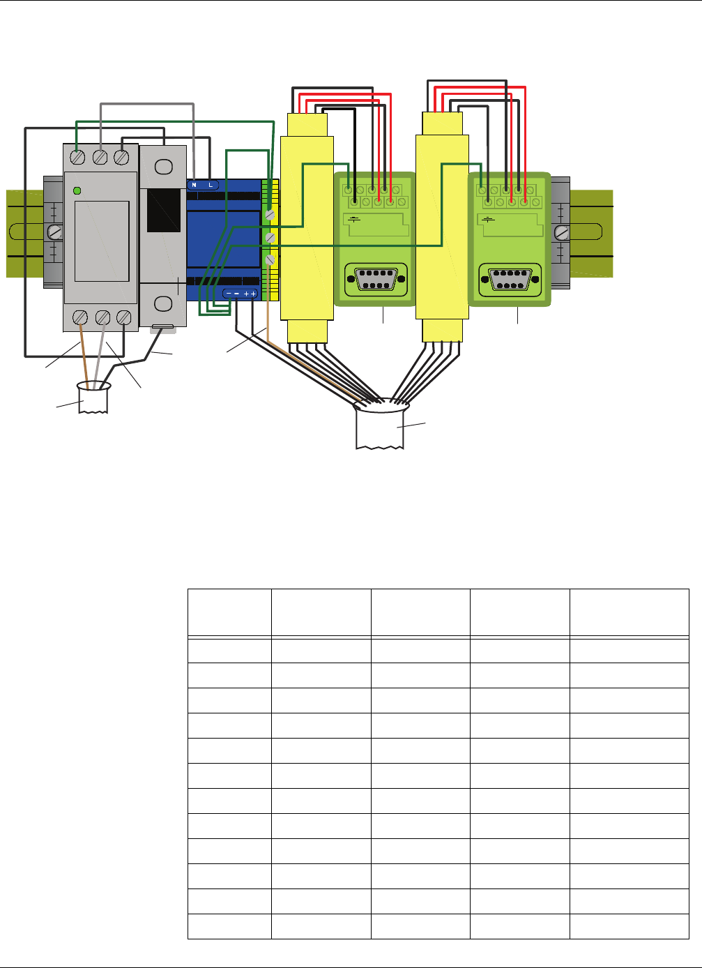
Autoscope RTMS Sx-300 Interface Panels
RTMS Sx-300 User Guide ©2014 Image Sensing Systems Inc. B-10
DIN Rail Power and RS-232 & RS-422/485 Interface Panel (P/N A600-1098)
Figure B-8: Power and RS-232 and RS-422/485 Interface Panel Wiring
MTL
1 2 3 4 5
1 2 3 4 5
UNPROTECTED
PROTECTED
RS-232 DB9
Female Connector RS-422/485 DB9 Female Connector
(to PC or TMC comm link)
DSP60-24
DCPw
0V
GNL
UNPROTECTED
POWER /
PROTECTED
GNL
12345
6789
PROTECTED
UNPROTECTED
12 34S
1234S
12345
6789
110 VAC
Power
Protect Ckt Bkr
(2 Amp)
24 VDC
Power
RS-232
Protection
RS-422/485
Protection
Backplate/DIN rail must
be connected to earth
ground at install time.
NOTE:
Note, must provide earth ground
conductor from utility.
Hot
Neutral
Ground
110 VAC
Power Cable MS Cable
Shield
Table B-10: MS Cable Wiring for Power and RS-232 and RS422/485 Interface
Panel
MS Cable
Pin
RS-232
Protect Pin
RS-422/48
Protect Pin
24 VDC
Power Pin Signal Name
g N/A N/A – DC GND
f N/A N/A + +24 VDC
e N/A 1 N/A TxD+ (422)
d N/A 2 N/A TxD– (422)
U5 SN/ASGND
W N/A 3 N/A RxD+ (422)
Z N/A 4 N/A RxD– (422)
X 1 N/A N/A CTS (232)
V 2 N/A N/A TxD (232)
T3N/AN/ARxD (232)
Y 4 N/A N/A RTS (232)
Shield N/A N/A – Earth GND
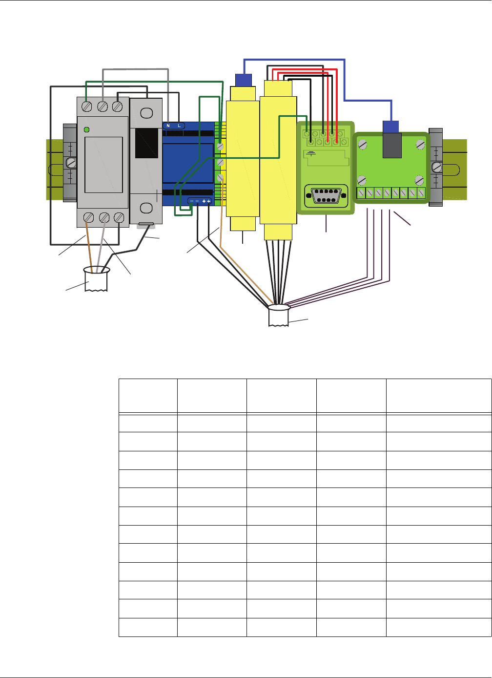
Autoscope RTMS Sx-300 Interface Panels
RTMS Sx-300 User Guide ©2014 Image Sensing Systems Inc. B-11
DIN Rail Power and RS-232 and TCP/IP Interface Panel (P/N A600-1097)
Figure B-9: Power and RS-232 and TCP/IP Interface Panel Wiring
Table B-11: MS Cable Wiring for Power and RS-232 and TCP Interface Panel
MS Cable
Pin
RS-232
Protect Pin
TCP/IP
Protect Pin
24 VDC
Power Pin Signal Name
g N/A N/A – DC GND
f N/A N/A + +24 VDC
eN/A 2 N/A TX– (TCP)
dN/A 1 N/A TX+ (TCP)
U 5 N/A N/A SGND
W N/A 3 N/A RX+ (TCP)
Z N/A 6 N/A RX– (TCP)
X 1 N/A N/A CTS (232)
V 2 N/A N/A TxD (232)
T3N/AN/ARxD (232)
Y4N/AN/ARTS (232)
Shield N/A N/A – Earth GND
RS-232 DB9
Female Connector
(to PC or TMC
comm link)
MTL
1 2 3 4 5
UNPROTECTED
PROTECTED
1 2 3 4 5
RJ-45 Terminals
DSP60-24
DCPwr
0V
GNL
UNPROTECTED
POWER /
PROTECTED
GNL
PROTECTED
UNPROTECTED
RJ-45
RJ-45
12345
6789
1 ... 8
Backplate/DIN rail must
be connected to earth
ground at install time.
NOTE:
RS-232
Protection
110 VAC
Power
Protect Ckt Bkr
(2 Amp)
24 VDC
Power TCP/IP
Protection
RJ-45 Terminations
(to RTMS)
Note, must provide earth ground
conductor from utility.
Hot
Neutral
Ground
110 VAC Power Cable
MS Cable
Shield
To PC
{
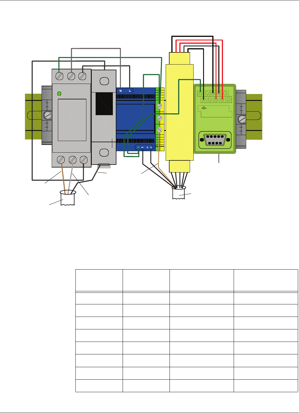
Autoscope RTMS Sx-300 Interface Panels
RTMS Sx-300 User Guide ©2014 Image Sensing Systems Inc. B-12
DIN Rail Power and RS-485 Interface Panel (P/N A600-1100)
Figure B-10: Power and RS-485 Interface Panel Wiring
RS-485 DB9 Female Connector
(to PC or TMC comm link)
DSP60-24
DCPwr
0V
GNL
UNPROTECTED
POWER /
PROTECTED
GNL
12345
6789
PROTECTED
UNPROTECTED
12 34S
1234S
Backplate/DIN rail mus
be connected to earth
ground at install time.
NOTE:
110 VAC
Power
Protect Ckt Bkr
(2 Amp)
24 VDC
Power RS-485
Protection
Note, must provide earth ground
conductor from utility.
Hot
Neutral
Ground
110 VAC Power Cable
MS Cable
Shield
Table B-12: MS Cable Wiring for Power and RS-485 Interface Panel
MS Cable Pin RS-485
Protect Pin 24 VDC Power Pin Signal Name
g N/A – DC GND
f N/A + +24 VDC
X1 N/A TxD+
V2 N/A TxD–
U S N/A SGND
T3 N/A RxD–
Y4 N/A RxD+
Shield N/A – Earth GND

RTMS Sx-300 User Guide ©2014 Image Sensing Systems Inc. C-1
Appendix C: Data Files and Message
Formats
Traffic Data Files
The text file that is created is identified by the extension “.asc”. The file is formatted
in a table form.
The files contain Time/Date stamped data from one or more sensors. The format of the
file is shown below.
1 RTMS STAT. MESSAGES ZONE: 1 2 3 4 5 6 7 8
2 SPEED IN Units. Occupancy 6 ft loop normalized.
3 DDMMYYYY HH:MM:SS
4 MESSAGE NO. # VOLUME: 0 0 0 0 0 0 0 0
5 REG: 0 0 0 0 0 0 0 0
6 MED: 0 0 0 0 0 0 0 0
7 LARGE: 0 0 0 0 0 0 0 0
8 TRUCK: 0 0 0 0 0 0 0 0
9 XLARGE: 0 0 0 0 0 0 0 0
10 STATION ID. # OCCUPANCY: 0.0 0.0 0.0 0.0 0.0 0.0 0.0 0.0
11 FWDLK SPEED ? SIDEFRD SPD: 0 0 0 0 0 0 0 0 Dir. 0 V.0 H.0
12 GAP: 0.0 0.0 0.0 0.0 0.0 0.0 0.0 0.0
Figure C-1: Autoscope RTMS Sx-300 .asc Fle Format (X3 STAT protocol)
Table C-1: File Format Description
Line Description
1 Header for the following Rows.
2 Header information.
Speed in units — The speed values in the table are in these units.
Occupancy … — If the 6ft emulation is turned this message is displayed.
3 Date and Time Stamp.
(Table continues on the next page)

Traffic Data Files
RTMS Sx-300 User Guide ©2014 Image Sensing Systems Inc. C-2
4Message No. — The message number. It will go from 0 to 255. On the
256th message it will be message 0 again.
Vol ume — This is the total volume for each zone.
** Note: To calculate “Small” classification, add up the individual
classifications listed below and subtract that number from the total
volume.
5 Volume counts for each zone for the Regular Class size.
6 Volume counts for each zone for the Medium Class size.
7 Volume counts for each zone for the Large Class size.
8 Volume counts for each zone for the Truck Class size.
9 Volume counts for each zone for the Extra Large Class size.
10 Station ID — This is the sensor ID. Set in Manual Settings -> Sensor ID
Occupancy — The occupancy value for each zone.
11 FWDLK SPEED — Not used.
SideFrd SPD — The is the speed value for each zone when using the
Side-Fired or Midblock modes.
Dir — This is the direction value when using the forward looking mode
(this value is sometimes needed when troubleshooting with Technical
Support personnel).
V — This is the voltage reading at the Autoscope RTMS Sx-300. This is a
real number reported as a whole number. For example 239 equals 23.9 V.
The maximum value that can be shown is 25.5.
H — This is a Health Byte value. This is only used for troubleshooting
purposes with Technical Support personnel.
12 The Gap or Headway values for each zone.
Table C-1: File Format Description (Cont’d)
Line Description

Sample X3 Compatible Statistical Message
RTMS Sx-300 User Guide ©2014 Image Sensing Systems Inc. C-3
Sample X3 Compatible Statistical Message
The X3 message format will:
•Always display all eight zones even if fewer zones are setup.
•Always displays speed values in Km/h.
•The designation vehicle classes will only display the number of classifications
shown in the Autoscope RTMS Setup Utility.
The following is a sample X3 STAT file with six length classes reporting.
RTMS STAT. MESSAGES ZONE: 1 2 3 4 5 6 7 8
SPEED IN Km/h.Occupancy 6 ft loop normalized.
27 11 2012 10:03:34
MESSAGE NO. 45 VOLUME: 0 0 0 0 0 0 0 0
MID SIZE 1: 0 0 0 0 0 0 0 0
LONG VEH 1: 0 0 0 0 0 0 0 0
XLONG VEH: 0 0 0 0 0 0 0 0
STATION ID. 2 OCCUPANCY: 0 0 100 0 0 0 0 0
FWDLK SPEED ? SIDEFRD SPD: ? ? 0 ? ? ? ? ? Dir. 128 V. 251 H. 16
27 11 2012 10:03:44
MESSAGE NO. 46 VOLUME: 0 0 0 0 0 0 0 0
MID SIZE 1: 0 0 0 0 0 0 0 0
LONG VEH 1: 0 0 0 0 0 0 0 0
XLONG VEH: 0 0 0 0 0 0 0 0
STATION ID. 2 OCCUPANCY: 0 0 100 0 0 0 0 0
FWDLK SPEED ? SIDEFRD SPD: ? ? 0 ? ? ? ? ? Dir. 128 V. 251 H. 16
27 11 2012 10:03:54
MESSAGE NO. 47 VOLUME: 0 0 0 0 0 0 0 0
MID SIZE 1: 0 0 0 0 0 0 0 0
LONG VEH 1: 0 0 0 0 0 0 0 0
XLONG VEH: 0 0 0 0 0 0 0 0
STATION ID. 2 OCCUPANCY: 0 0 100 0 0 0 0 0
FWDLK SPEED ? SIDEFRD SPD: ? ? 0 ? ? ? ? ? Dir. 128 V. 254 H. 16
Figure C-2: Sample X3 STAT

G4 Statistical Message
RTMS Sx-300 User Guide ©2014 Image Sensing Systems Inc. C-4
G4 Statistical Message
Please note:
•G4 Statistics Message will have a variable length based on how many lanes
are configured.
•The designation of vehicle classes will also be the same as shown in the
Autoscope RTMS Setup Utility.
•If Per Vehicle is ON, their data will be ahead of each message period’s
statistics.
The following is a sample G4 STAT file with all 12 lanes and 6 length classes
reporting.
RTMS STAT. MESSAGES ZONE: 1 2 3 4 5 6 7 8 9 10 11 12
SPEED IN Km/h. Occupancy 6 ft loop normalized.
03 27 2011 1:40:00
MESSAGE NO. 250 VOLUME: 8 8 11 7 20 10 12 14 9 11 13 11
REG: 2 0 0 0 1 1 1 1 1 1 3 1
MED: 0 0 1 0 1 2 0 0 0 1 1 1
LARGE: 0 1 0 0 0 0 1 0 0 0 2 2
TRUCK: 0 0 1 0 0 0 0 2 0 1 0 0
XLARGE: 0 0 2 0 0 0 0 0 0 0 2 0
STATION ID. 1 OCCUPANCY: 5.6 5.1 12.4 4.4 17.5 11.5 9.3 13.0 6.3 8.7 16.6 10.0
FWDLK SPEED ? SIDEFRD SPD: 52 65 60 58 50 57 55 63 48 66 63 62 Dir. 0 V.239 H.0
03 27 2011 1:41:00
MESSAGE NO. 251 VOLUME: 7 9 11 10 18 12 10 10 12 8 7 6
REG: 1 3 2 0 7 3 3 2 1 0 2 0
MED: 1 0 0 1 0 0 0 0 0 1 2 3
LARGE: 0 0 1 0 0 0 1 0 0 0 0 0
TRUCK: 0 0 1 0 0 0 0 3 0 0 0 0
XLARGE: 0 0 0 1 0 1 0 0 1 0 0 1
STATION ID. 1 OCCUPANCY: 5.4 5.2 12.4 11.5 16.8 9.4 11.5 10.9 7.4 7.8 4.4 4.1
FWDLK SPEED ? SIDEFRD SPD: 53 64 58 60 52 54 58 64 47 66 66 64 Dir. 0 V.239 H.0
Figure C-3: Sample G4 STAT File

Statistical Message with Per Vehicle On
RTMS Sx-300 User Guide ©2014 Image Sensing Systems Inc. C-5
Statistical Message with Per Vehicle On
For more information about the Per Vehicle setting, see “Defining Per Vehicle
Messages” on page 5-31.
RTMS STAT. MESSAGES ZONE: 1 2 3 4 5 6 7 8 9 10 11 12
SPEED IN Km/h.Occupancy 6 ft loop normalized.
27 11 2012 10:11:24
MESSAGE NO. 92 VOLUME: 0 0 1 0 0 0 0 0 0 0 0 0
MED: 0 0 0 0 0 0 0 0 0 0 0 0
LARGE: 0 0 0 0 0 0 0 0 0 0 0 0
TRUCK: 0 0 0 0 0 0 0 0 0 0 0 0
STATION ID. 2 OCCUPANCY: 0.0 0.0 47.2 0.0 0.0 0.0 0.0 0.0 0.0 0.0 0.0 0.0
FWDLK SPEED ? SIDEFRD SPD: ? ? 1 ? ? ? ? ? ? ? ? ? Dir. 128 V. 251 H. 16
HEADWAY: 10.0 10.0 5.0 10.0 10.0 10.0 10.0 10.0 10.0 10.0 10.0 10.0
pv RTMS_ID Lane Class Speed[km/h] Length[m] Dwell
pv --------------------------------------------------
pv 27 11 2012 10:11:26.470 2 3 Sm 1 3.4 602
pv 27 11 2012 10:11:27.090 2 2 Sm 20 2.0 62
pv 27 11 2012 10:11:28.220 2 3 Sm 3 2.0 139
pv 27 11 2012 10:11:28.690 2 1 Sm 26 2.0 53
pv 27 11 2012 10:11:28.710 2 3 Sm 6 2.0 70
pv 27 11 2012 10:11:33.400 2 3 Sm 14 2.0 77
pv 27 11 2012 10:11:33.420 2 1 Trk 26 26.8 397
pv 27 11 2012 10:11:33.730 2 2 Sm 36 2.0 41
27 11 2012 10:11:34
MESSAGE NO. 93 VOLUME: 2 2 4 0 0 0 0 0 0 0 0 0
MED: 0 0 0 0 0 0 0 0 0 0 0 0
LARGE: 0 0 0 0 0 0 0 0 0 0 0 0
TRUCK: 1 0 0 0 0 0 0 0 0 0 0 0
STATION ID. 2 OCCUPANCY: 44.8 10.2 64.0 0.0 0.0 0.0 0.0 0.0 0.0 0.0 0.0 0.0
FWDLK SPEED ? SIDEFRD SPD: 26 28 6 ? ? ? ? ? ? ? ? ? Dir. 128 V. 251 H. 16
HEADWAY: 14.8 6.8 2.9 10.0 10.0 10.0 10.0 10.0 10.0 10.0 10.0 10.0
pv RTMS_ID Lane Class Speed[km/h] Length[m] Dwell
pv --------------------------------------------------
pv 27 11 2012 10:11:37.600 2 2 Trk 36 27.6 297
pv 27 11 2012 10:11:42.510 2 3 Sm 7 9.0 529
Figure C-4: Sample File With Per Vehicle ON

Statistical Message with Per Vehicle On
RTMS Sx-300 User Guide ©2014 Image Sensing Systems Inc. C-6
Table C-2: Per Vehicle Message Field Descriptions
Field Description
RTMS_ID Sensor ID of the Autoscope G4.
Lane Lane number the vehicle was detected in.
Class Classification of the detected vehicle.
Speed Speed of the detected vehicle.
Length Length of the detected classification.
Dwell Number of milliseconds the vehicle is being detected.

RTMS Sx-300 User Guide ©2014 Image Sensing Systems Inc. D-1
Appendix D: Bluetooth Device
Operations
General
IMPORTANT: Bluetooth shares serial port 1 in the Autoscope RTMS Sx-300;
therefore, any physical connection to port 1 must be disconnected so
that communications to the Autoscope RTMS Sx-300 via bluetooth
can be established.
Before you can set up Bluetooth communications with the Autoscope RTMS Sx-300,
use the manufacturer’s instructions to install a Bluetooth device on your computer.
Some computers come with pre-installed Bluetooth capabilities. We recommend that
you determine the specifications of the internal Bluetooth adapter prior to establishing
a link to the Autoscope RTMS Sx-300. Using the internal Bluetooth adapter may not
give you adequate range to establish a reliable link to the Autoscope RTMS Sx-300.
NOTES:
•It is recommended that at least Bluetooth 2.0+EDR Class 1, and strongly
recommends the Sena Parani UD100-G03 USB Bluetooth adapter.
•Bluetooth requires that the baud rate for port 1 in the Autoscope RTMS Sx-
300 be set to 115,200, which is the default setting.
There are three classes of Bluetooth devices. The different classes have different
ranges as follows:
•Class 3 radios – 1 m (3 ft)
•Class 2 radios – 10 m (33 ft): most commonly found in mobile devices
•Class 1 radios – 100 m (328 ft): used primarily in industrial use cases
Bluetooth is not a line-of-sight connection, so it can be used through walls and floors.
However, things such as walls, people, poles and vehicles can reduce the range.
The following sections describe how to locate and connect to a Bluetooth device when
using recommended Sena Parani adapter or through Microsoft Windows.

Method 1: Using the Sena Parani UD100-G03 USB Adapter
RTMS Sx-300 User Guide ©2014 Image Sensing Systems Inc. D-2
Method 1: Using the Sena Parani UD100-G03 USB Adapter
This is the Bluetooth adapter that is recommended for communicating with the
Autoscope RTMS Sx-300.
Determining if Your Computer Has Bluetooth Installed
To determine whether your computer has a bluetooth device, look for the Bluetooth
icon in the system tray at the lower right of your screen. If it does not appear, follow
the manufacturer’s instruction for installing the Bluetooth device.
Pairing With and Connecting to the Autoscope RTMS Sx-300
IMPORTANT: Before performing this procedure you must set up the Autoscope
RTMS Sx-300 to communicate with a Bluetooth device (the
Communication screen must be set to PC serial and the Baudrate
must be set to 115,200). For additional information see “Defining a
Bluetooth Connection” on page 5-11.
To connect to the Autoscope RTMS Sx-300 using Bluetooth communication, do the
following.
1. Make sure the Autoscope RTMS Sx-300 is powered up and within range of your
computer.
2. Double-click the Bluetooth icon in the system tray.
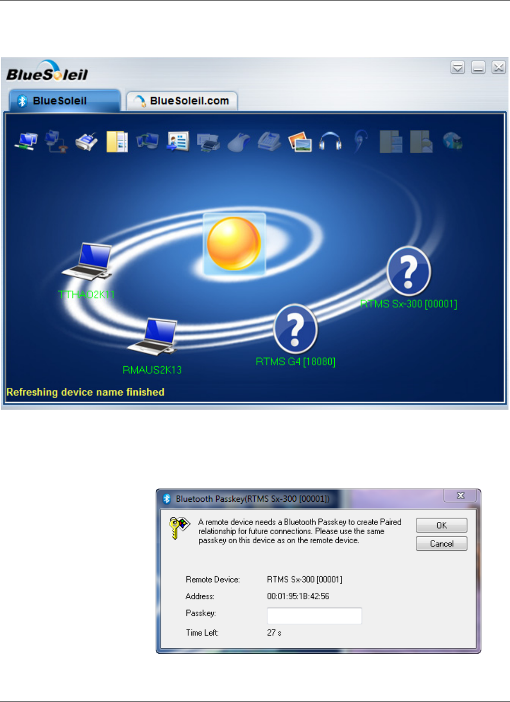
Method 1: Using the Sena Parani UD100-G03 USB Adapter
RTMS Sx-300 User Guide ©2014 Image Sensing Systems Inc. D-3
The following window appears.
3. Wait for the correct device names to appear on the display.
4. Double-click on the RTMS Sx-300 sensor.
The following window appears.
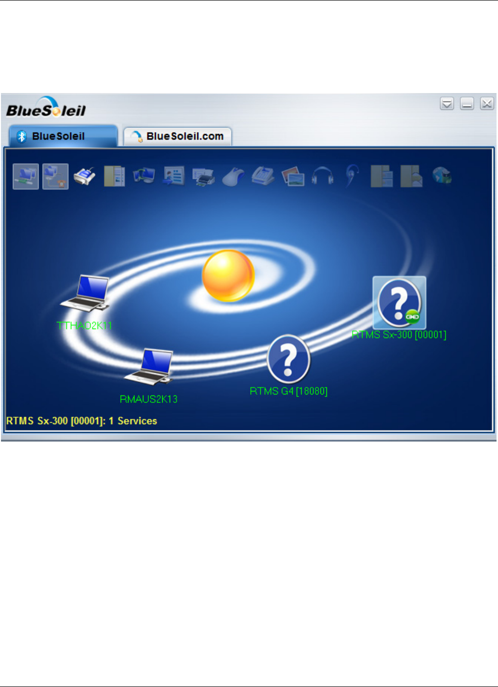
Method 1: Using the Sena Parani UD100-G03 USB Adapter
RTMS Sx-300 User Guide ©2014 Image Sensing Systems Inc. D-4
5. In the Bluetooth Passkey (PIN) field, type admin.
6. Click OK.
The following window appears.
Note that a green circle appears by the selected sensor.
7. Right-click on the sensor and select Connect Bluetooth Serial Port.
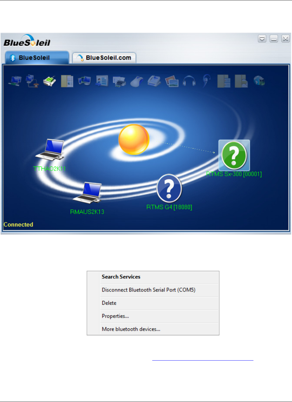
Method 1: Using the Sena Parani UD100-G03 USB Adapter
RTMS Sx-300 User Guide ©2014 Image Sensing Systems Inc. D-5
Wait until the following appears.
The question mark turns green and Connected appears in the lower right of the
window.
8. Right-click on the sensor and make note of the COM port listed.
In the above sample, the COM port is 5.
9. Start the Setup Utility (see “Starting the Setup Utility” on page 3-7).
10. On the Main Screen, click Manual Settings.
11. On the Manual Setup screen, click Communication.
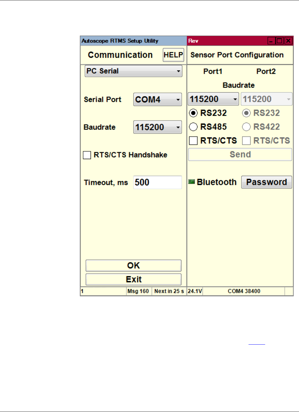
Method 1: Using the Sena Parani UD100-G03 USB Adapter
RTMS Sx-300 User Guide ©2014 Image Sensing Systems Inc. D-6
The following screen appears.
NOTE: You can also get to this screen by clicking the Communication button on the
Start screen.
12. Select PC Serial as the type of communication.
13. For Serial Port, select the serial port that you made note of in Step 8.
14. For Baudrate, select 115200 (this is mandatory for Bluetooth).
15. For Timeout, ms, the default value, 500, is recommended.

Method 1: Using the Sena Parani UD100-G03 USB Adapter
RTMS Sx-300 User Guide ©2014 Image Sensing Systems Inc. D-7
16. Click OK.
If a connection is established, the green COM indicator in the bottom right of the
screen will be blinking.
17. You can now perform any of the Setup Utility operations.
IMPORTANT: After you are through with the Autoscope RTMS Setup Utility, it is
strongly recommended that you disconnect and delete the Bluetooth
connection. If not, Windows will retain the COM Port settings,
which could cause issues with the COM port settings on your
computer. See “Disconnecting Bluetooth” on page D-8.
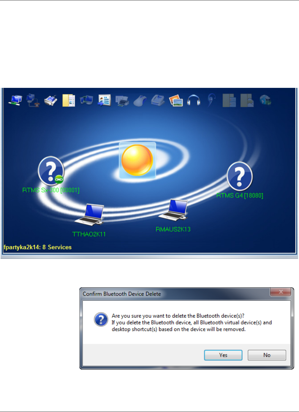
Method 1: Using the Sena Parani UD100-G03 USB Adapter
RTMS Sx-300 User Guide ©2014 Image Sensing Systems Inc. D-8
Disconnecting Bluetooth
To disconnect from the Autoscope RTMS Sx-300 and delete the Bluetooth
connection, do the following.
1. Exit the Autoscope RTMS Setup Utility.
2. Double-click the Bluetooth icon in the System tray.
The following window appears.
3. Right-click the Autoscope RTMS Sx-300 sensor and select Delete.
The following window appears.
4. Click Ye s .
The sensor disappears from the display.
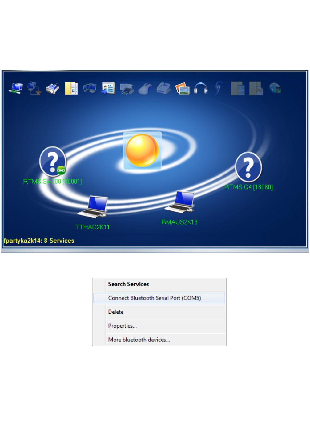
Method 1: Using the Sena Parani UD100-G03 USB Adapter
RTMS Sx-300 User Guide ©2014 Image Sensing Systems Inc. D-9
Finding the Bluetooth COM Port Assignment
To find out what COM port the Bluetooth adapter is assigned to, do the following.
1. Double-click the Bluetooth icon in the System tray.
The following window appears.
2. Right-click the Autoscope RTMS Sx-300 sensor.
Make note of the COM port listed. Note, it is not necessary to connect to the
sensor.
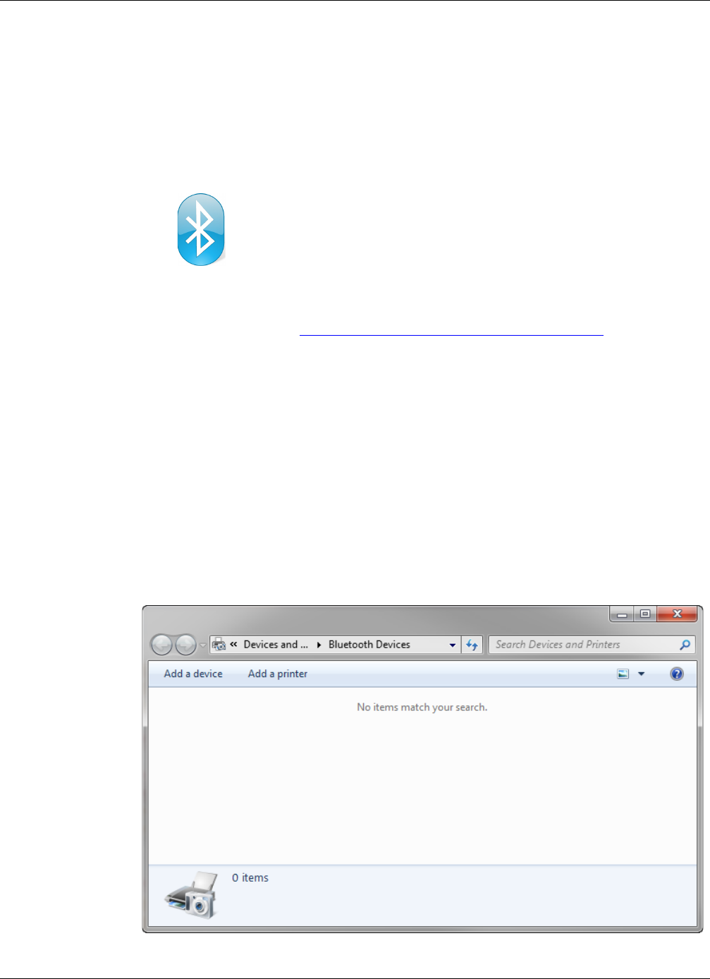
Method 2: Using Microsoft Windows
RTMS Sx-300 User Guide ©2014 Image Sensing Systems Inc. D-10
Method 2: Using Microsoft Windows
NOTE: The following information is applicable for Windows 7 operating systems.
Determining if Your PC has Bluetooth Installed
To determine whether your computer has a bluetooth device, look for the Bluetooth
icon in the system tray at the lower right of your screen.
If the icon is in the tray, you can set up Bluetooth communications with the Autoscope
RTMS Sx-300 (see “Defining a Bluetooth Connection” on page 5-11.
If there is no Bluetooth adapter installed. Install a Bluetooth adapter and software
according to the manufacturer’s instructions
Search For and Connect to A Bluetooth Device
The following describes how to see if the Autoscope RTMS Sx-300 is setup as a
Bluetooth device.
1. Make sure the Autoscope RTMS Sx-300 (with internal Bluetooth option) is
powered up and within range of your computer.
2. Double-click the bluetooth icon in the system tray.
The following window appears.
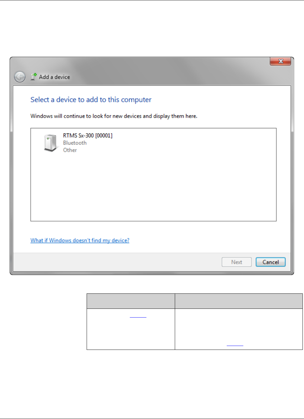
Method 2: Using Microsoft Windows
RTMS Sx-300 User Guide ©2014 Image Sensing Systems Inc. D-11
3. Click Add a device.
A search for Bluetooth devices is conducted. When the search is complete, the
following window appears
4. Is the Autoscope RTMS Sx-300 listed in the window?
5. Double-click the RTMS Sx-300 sensor.
Ye s No
Continue with Step 5. a) Make sure the Autoscope RTMS Sx-300
is on and you are within range.
b) Click Search Again.
c) Continue with Step 5.
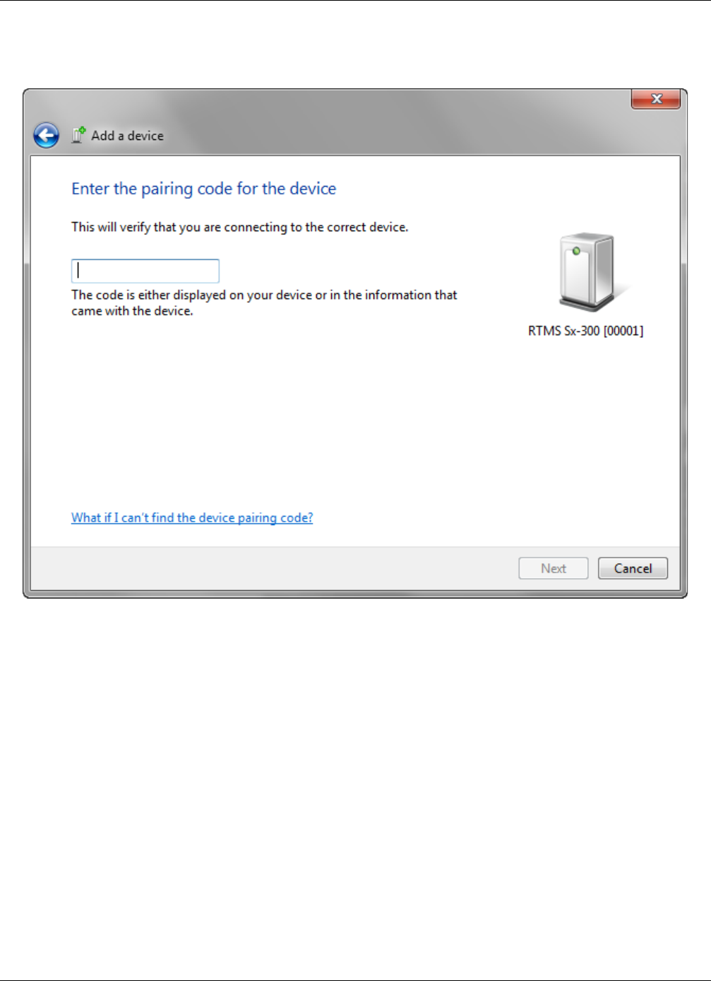
Method 2: Using Microsoft Windows
RTMS Sx-300 User Guide ©2014 Image Sensing Systems Inc. D-12
The following window appears.
6. Enter admin.
7. Click Next.
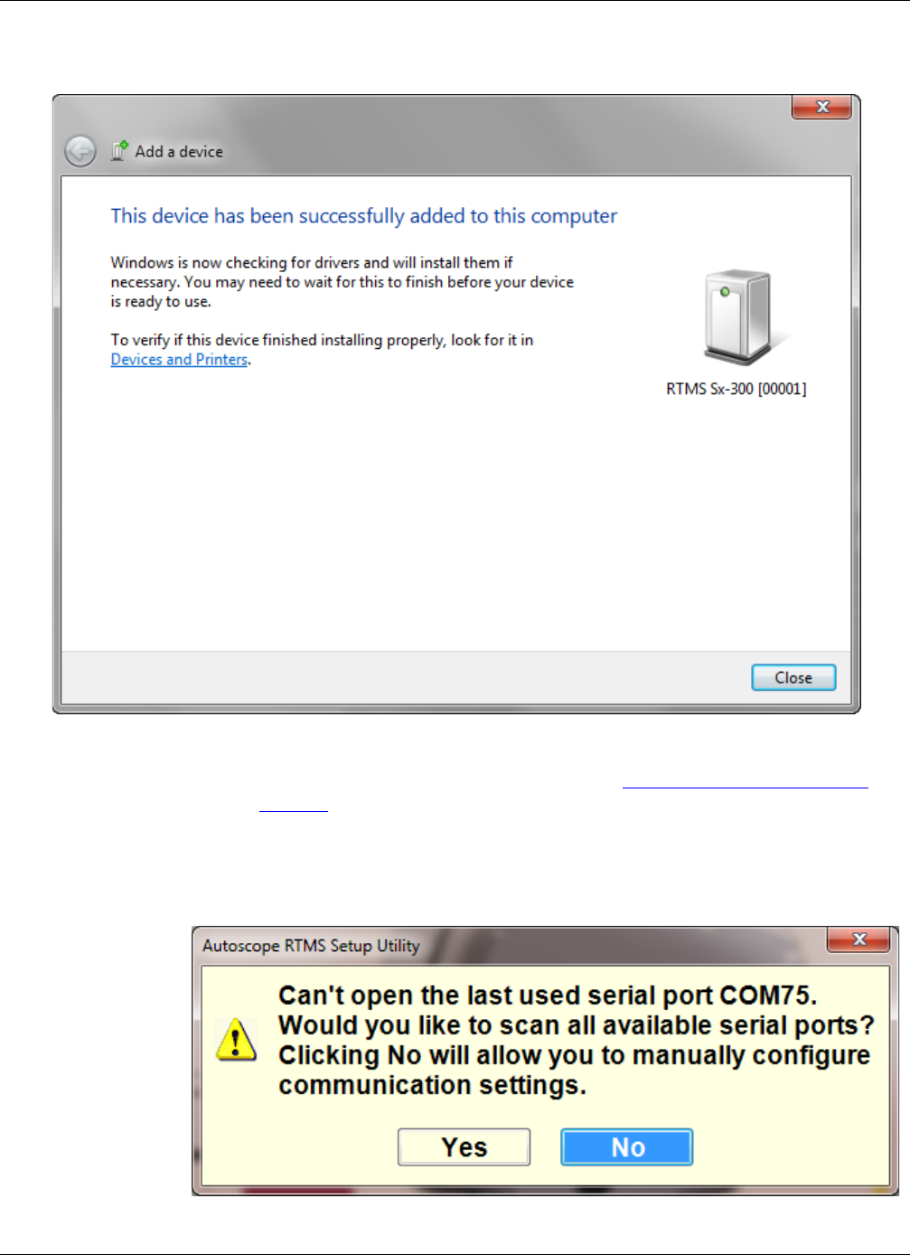
Method 2: Using Microsoft Windows
RTMS Sx-300 User Guide ©2014 Image Sensing Systems Inc. D-13
Wait for the following window to appear.
8. Click Close.
9. Start the Autoscope RTMS Setup Utility (see “Starting the Setup Utility” on
page 3-7).
The Main screen should appear.
NOTE: If the following window appears, click Yes .
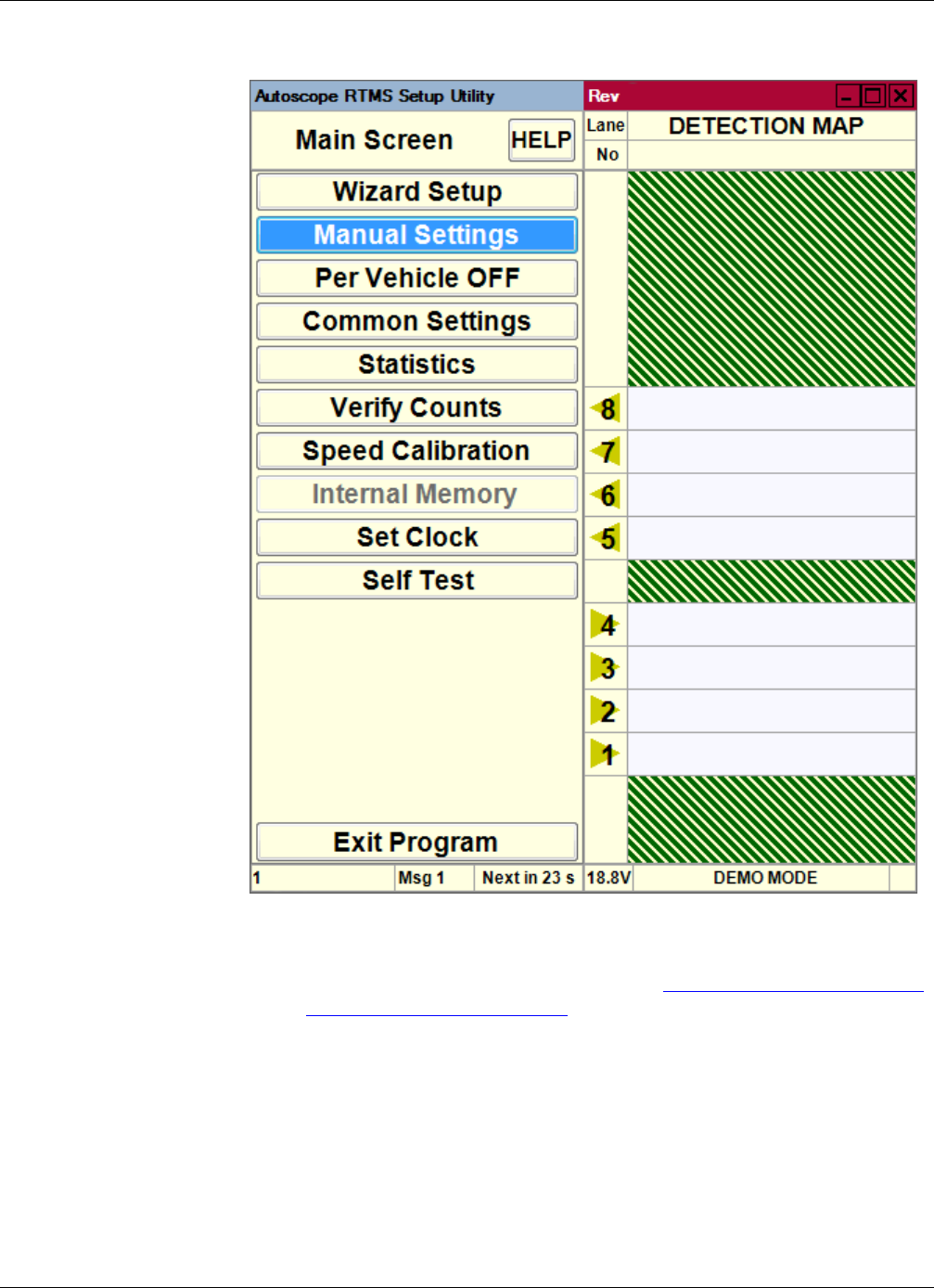
Method 2: Using Microsoft Windows
RTMS Sx-300 User Guide ©2014 Image Sensing Systems Inc. D-14
NOTE: If something other than the Main screen apperas, it is possible there is a
problem with the COM port assignment for your bluetooth device. If this
occurs, try using a different COM port (see “Changing the Bluetooth COM
Port Assignment” on page D-16.
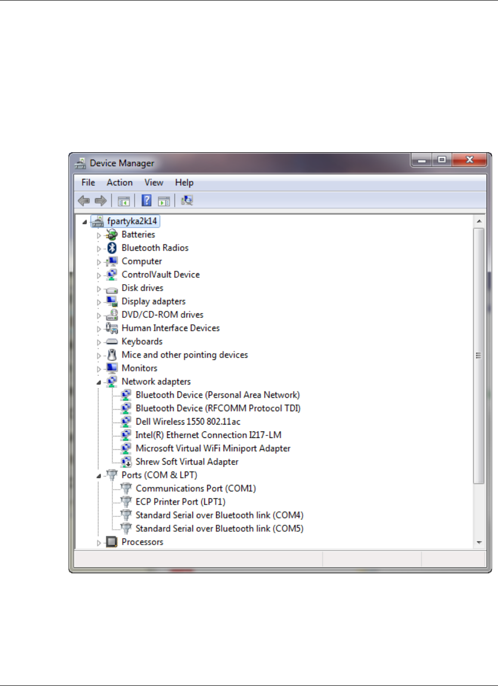
Method 2: Using Microsoft Windows
RTMS Sx-300 User Guide ©2014 Image Sensing Systems Inc. D-15
Finding the Bluetooth COM Port Assignment
The following describes how to find out what COM port the Bluetooth adapter is
assigned to.
1. Select Start>Control Panel.
2. Click Device Manager.
The following window appears.
3. Expand Ports (COM &LPT).
The first COM port listed is the outgoing port number, which is the one used when
trying to connect to the Autoscope RTMS Sx-300. In the above, COM4 is the
outgoing port.
4. Close the Device Manager.

Method 2: Using Microsoft Windows
RTMS Sx-300 User Guide ©2014 Image Sensing Systems Inc. D-16
Changing the Bluetooth COM Port Assignment
The following describes how to change theCOM port the Bluetooth adapter is
assigned to.
1. Select Start>Control Panel.
2. Click Device Manager.
The following window appears.
3. Expand Ports (COM &LPT).
4. Right-click on the port to be change.
5. Select Properties.
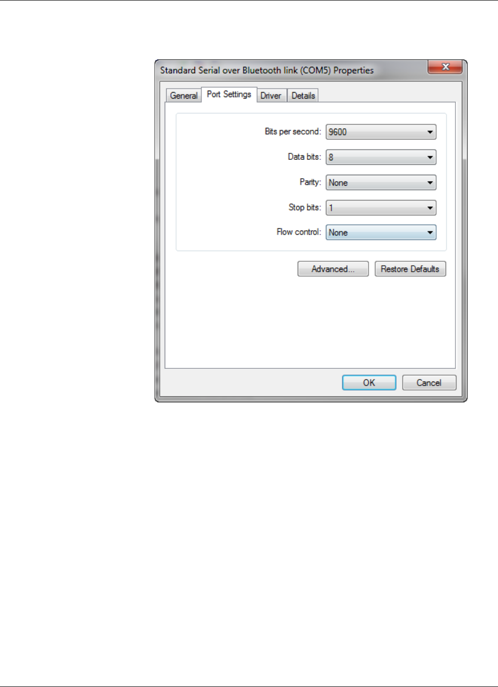
Method 2: Using Microsoft Windows
RTMS Sx-300 User Guide ©2014 Image Sensing Systems Inc. D-17
The following window appears.
6. Select the Port Settings tab.
7. Click Advanced.
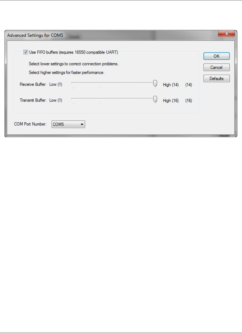
Method 2: Using Microsoft Windows
RTMS Sx-300 User Guide ©2014 Image Sensing Systems Inc. D-18
The following window appears.
8. Use the drop-down to select the new COM port to be used.
9. Click OK.
10. Close the Device Manager.
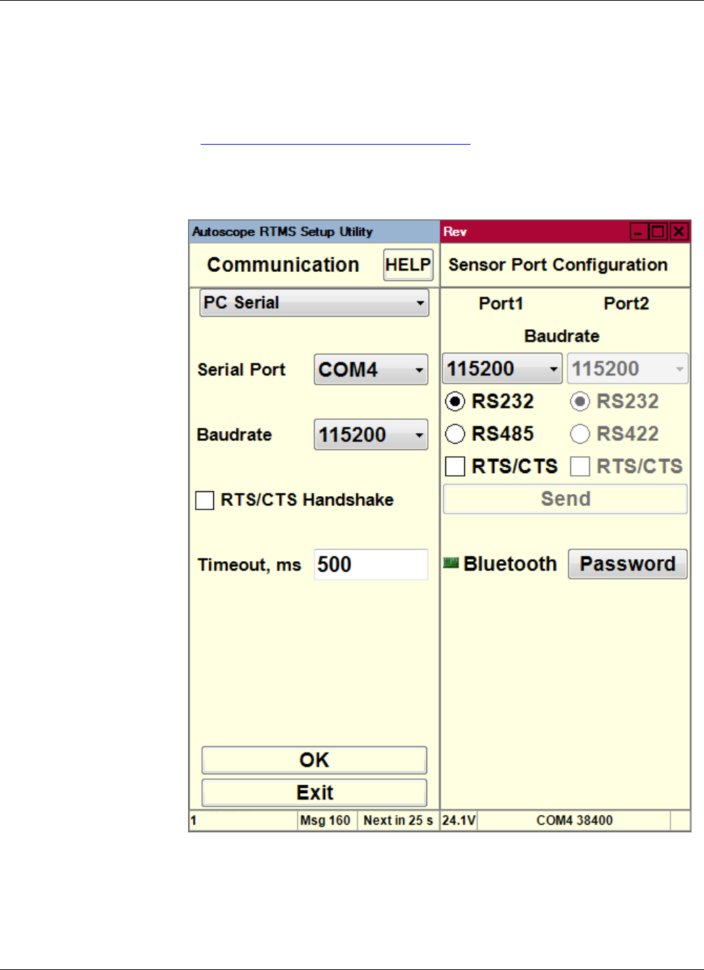
Changing the Bluetooth Password/Passkey
RTMS Sx-300 User Guide ©2014 Image Sensing Systems Inc. D-19
Changing the Bluetooth Password/Passkey
The default password/passkey for the Autoscope RTMS Sx-300 Bluetooth connection
is admin. If you would like to change this, use the following procedure.
1. Connect to the Autoscope RTMS Sx-300 through Direct serial connection (see
“Defining a Serial Connection” on page 5-9).
NOTE: DO NOT use the Bluetooth connection.
NOTE: Make sure the Baudrate is set to 115200.
2. Click Password.
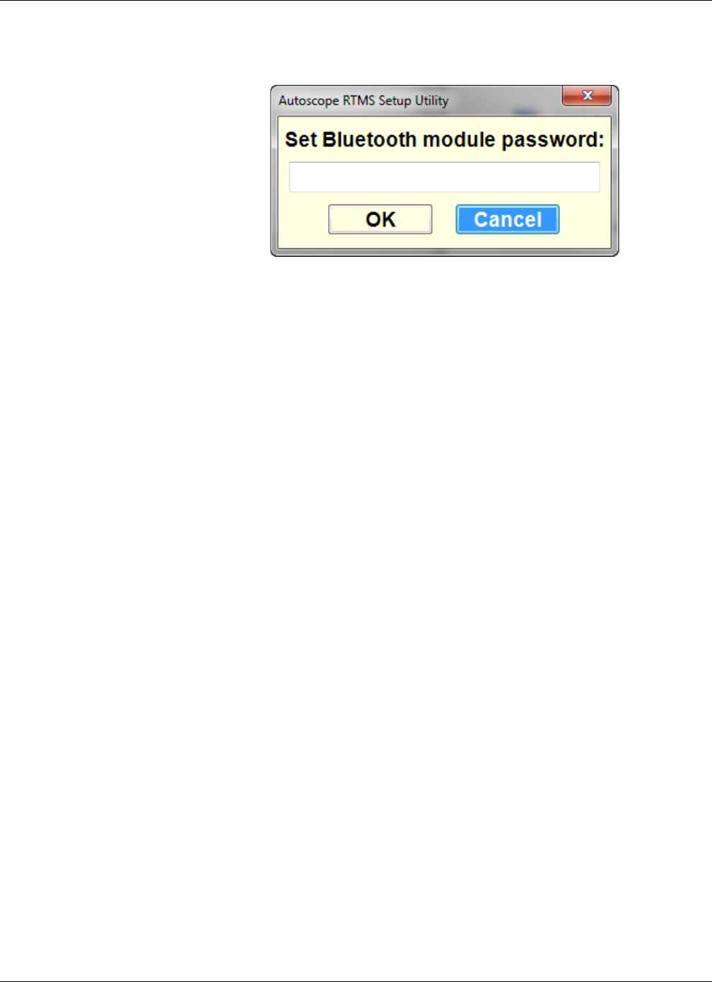
Changing the Bluetooth Password/Passkey
RTMS Sx-300 User Guide ©2014 Image Sensing Systems Inc. D-20
The following window appears.
3. Type the new password.
4. Click OK.

RTMS Sx-300 User Guide ©2014 Image Sensing Systems Inc. E-1
Appendix E: Speed Calibration Worksheet
General
This worksheet is used in conjunction with the speed calibration that must be run for
Autoscope RTMS Sx-300 sensors.
Run the Autoscope RTMS Sx-300 setup procedure for Speed Calibration (see “Calibrate
Speed” on page 4-15). Set Autoscope RTMS Sx-300 Message Period to 30 seconds. Run
Speed Calibration for at least 15 minutes. Speed should be at a steady flow, and at least 50% of
vehicles past the Autoscope RTMS Sx-300 should have a LIDAR reading. If you need to
complete Speed Calibration with the Manual option, please note it on the worksheet.
IMPORTANT: Speed Calibration is complete when all zones are less than ±10 Km/h (±6
MPH).
An online version of the worksheet is available in the same directory as this manual, or by
clicking the link in the Autoscope RTMS Sx-300 Speed Calibration Screen help file.
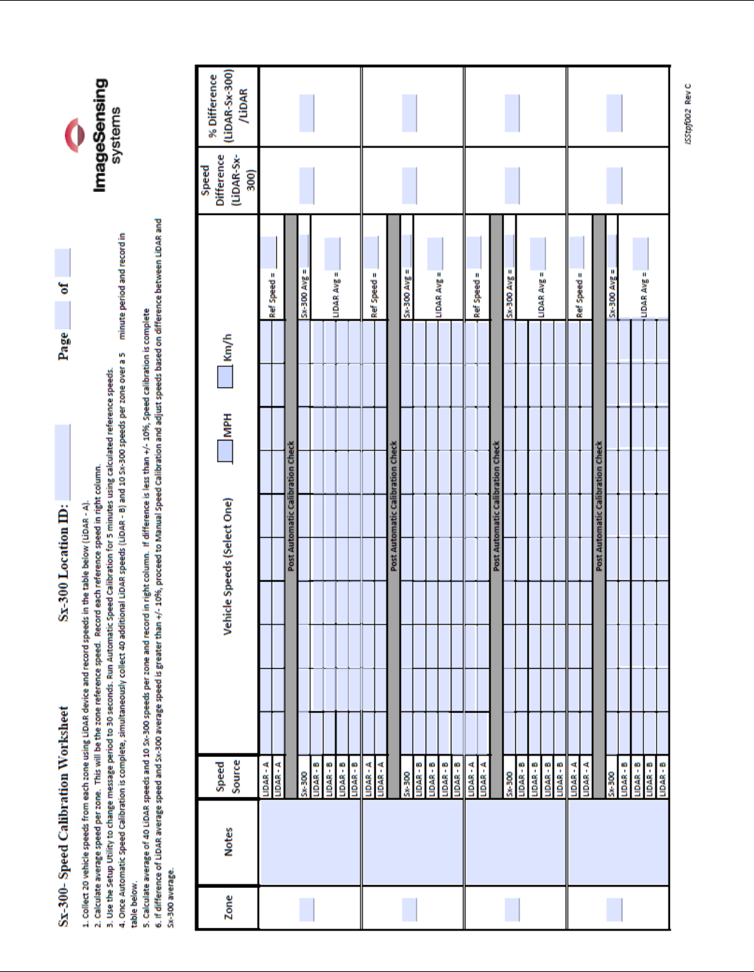
General
RTMS Sx-300 User Guide ©2014 Image Sensing Systems Inc. E-2

RTMS Sx-300 User Guide ©2014 Image Sensing Systems Inc. Glossary-1
Glossary
ADC (Analog to Digital Converter) A device that converts analog signals to digital signals.
AWG (American Wire Gauge) A U.S. measurement standard of the diameter of non-
ferrous wire, which includes copper and aluminum. In general, the thicker the wire,
the greater the current-carrying capacity and the longer the distance it can span. The
smaller the AWG number, the thicker the wire.
CB Abbreviation for Circuit Breaker.
CC (Contact Closure) One of the optional configurations available with Autoscope Sx-300
SSP.
CTS (Clear to Send) A signalling message transmitted from the data communications
equipment (DCE) indicating to the data terminal equipment (DTE) that it may begin
data transmission.
DB (Decibel) Used to indicate the level of acoustic waves and electronic signals.
DB9 A connector used for RS-232 connections and for several video interfaces on IBM-
compatible computers.
DIN Rail A standardized 35 mm wide metal rail with hat-shaped cross section. It is widely used
for mounting circuit breakers and industrial control equipment inside equipment racks.
DSP (Digital Signal Processing) The manipulation of analog information that has been
converted to a digital form.
Dual Loop An option that requires that all contacts share a common ground and provides eight
zones of detection. This option also provides eight primary and secondary outputs that
can be used to simulate the closure information that is collected from a dual loop
station.
FIFO (First In First Out) A method of organizing and manipulating data relative to time and
prioritization.
Gap The average time between the trailing edge of the previous vehicle and the leading
edge of the current vehicle.
GHz (Gigahertz) One billion cycles per second.
GND Abbreviation for electrical ground.
Headway The average time between the leading edge of the previous vehicle and the leading
edge of the current vehicle.

RTMS Sx-300 User Guide ©2014 Image Sensing Systems Inc. Glossary-2
High Z In polled mode, the transmit pin is in high impedance mode.
IP (Internet Protocol) a protocol used for communicating data across a packet-switched
internetwork using the Internet Protocol Suite, also referred to as TCP/IP.
Km/h Abbreviation for kilometers per hour.
LIDAR (Light Detecting and Ranging) A type of radar gun.
mA (Milliamp) One thousandth of an amp.
MB (Megabyte) A measure of data storage equal to 1,048,576 bytes.
MPH Abbreviation for miles per hour.
MHz (Megahertz) One million cycles per second.
NEMA (National Electrical Manufacturers Association) A U.S.-based association that defines
standards for many commonplace electrical interconnects, as well as outlining
manufacturing standards for electrical products, such as various grades of electrical
enclosures.
Occupancy The percentage of time a lane is occupied by a vehicle during the defined message
period.
PTS (Power Transient Suppressor) A device designed to react to a sudden or momentary
over voltage condition.
RS-232 A series of standards for serial binary single-ended data and control signals
connecting between a DTE and a DCE. It is commonly used in computer serial ports.
RS-422 A standard that specifies the characteristics of a digital signaling circuit. This type of
circuit is capable of transmitting data at rates of 10 million bps and can be sent on
cables as long as 1500 m (4921 ft).
RS-485 A serial interface standard in which data is sent in a differential pair (two wires or
(twisted pair), which allows for greater distances and higher data rates than RS-232.
RTC (Real Time Clock) A computer clock (often in the form of an integrated circuit) that
keeps track of the current time.
RTS (Request To Send) An RS-232 signal sent from the transmitting station to the
receiving station requesting permission to transmit.
RxD Abbreviation for received data.
Spd85 The speed at which 85 percent of the vehicles are at or below.

RTMS Sx-300 User Guide ©2014 Image Sensing Systems Inc. Glossary-3
TCP/IP (Transfer Control Protocol/Internet Protocol) Data transmission standard used by
many computer networks including the internet.
TxD Abbreviation for transmitted data.
USB (Universal Serial Bus) High-speed serial communications standard.
VAC Abbreviation for Volts Alternating Current
VDC Abbreviation for Volts Direct Current

Index
RTMS Sx-300 User Guide ©2014 Image Sensing Systems Inc. Index-1
Index
Numerics
6 ft loop 4-21
A
Accuracy of measurement 1-5
Adding zones 5-53
Adjusting
Sensitivity 5-47
Zone boundaries 5-55
Zones 4-8
Advanced screen 4-23
Aiming 5-34, 5-36, 5-37, 5-38
Application mode 3-23, 4-2
Assigning labels 5-58
Automatic speed calibration 4-15, 4-18
B
Barriers 2-8, 5-40
Baudrate 5-10, 5-12, 5-14
Beam footprint 1-2
Bluetooth 1-3
Changing COM port assignment D-16
Changing passkey D-19
Defining a connection 5-11
Device operations D-1
Finding COM port assignment D-9, D-15
Finding devices D-10
Breakout box 2-2, B-1
C
Cabling A-1
Cable pair requirements A-1
Connector kits A-2
Considerations 2-2
Max length A-2
Modems A-8
Notes 2-2
RS-232 wiring A-5
RS-485 multi-drop wiring A-7
RS-485 wiring A-6
Calibrating speed
Automatically 4-15, 4-18
Manually 5-24
Reference speed 4-15
Worksheet E-1
Changing
Communications options 5-17
Data mode 5-2
Message period 5-33
Classification options 4-22, 4-24
Clearing memory 5-30
Clock synchronization 3-20
Common settings 5-5
Communications 3-23, 5-7
Bluetooth 5-11
Changing 5-17
Considerations 2-2
Dialup connection 5-13
Serial connection 5-9
TCP/IP connection 5-15
Timeout 5-10, 5-12, 5-14, 5-16
Configuration process 4-1
Connecting to the sensor 3-7, 3-9
Contact closure A-1
D
Data format 5-44
Data mode options 3-23, 5-2
Data recording 5-44
Default settings 3-23
Deleting zones 5-53
Demo mode 3-10
Dialup connection 5-13
Downloading memory 5-27
Dwell time 5-31, C-6

Index
RTMS Sx-300 User Guide ©2014 Image Sensing Systems Inc. Index-2
E
Earth ground B-5, B-6
Electromagnetic interference 1-6
Elevated roadways 2-9
Environmental conditions 1-6
Error rates 1-5
F
Finding sensors 5-19
Fine tuning zones 5-52
Firmware upgrade 5-49
G
G4 message format C-4
G4 sensors 3-9, 5-21, 6-2
G4 stat mode 4-21
Gap 4-22
Ghost vehicle detection 2-10, 5-47
Grade differentials 2-11
Grounding B-5, B-6
Guard-rails 2-8
H
Handshaking 2-2, 5-10, 5-14
Hardware
Installation 2-1
Mounting 2-13
Headway 4-22
High resolution 4-21
High Z 5-4
I
Installation
Hardware 2-1
Software 3-1
Interface panel
RS-232 B-9, B-10, B-11
RS-422/485 B-10
RS-485 B-12
TCP/IP B-11
Internal memory 3-23
Introduction 1-1
L
Labelling zones 5-58
LIDAR 4-15
Loading
Common settings 5-5
Saved setup file 5-22
Low
Setback 2-8
Voltage power B-7
M
Manual settings screen 3-21
Manual speed calibration 5-24
Maximum cable lengths A-2
Mechanical specifications 1-3
Memory
Clearing 5-30
Downloading 5-27
Options 3-23, 5-25
Overwriting 5-26
Stop storing messages 5-26
Message
Composition 3-24, 4-20
Period 3-24, 5-33
Sample G4 format C-4
Sample X3 format C-3
Micro-slice 1-1, 5-55
Microwave signal specifications 1-4
Midblock 2-5, 2-12, 4-2, 4-3
Modems
Cabling A-7
Dialup connection 5-13
External A-7
Phone number 5-14
Sharing A-9
Mounting
Height chart 2-7
Procedure 2-13
MS connector pin outs A-3
Multidrop networks 3-9

Index
RTMS Sx-300 User Guide ©2014 Image Sensing Systems Inc. Index-3
N
NET Framework 3-1
O
Occlusion 2-5, 5-34
Occupancy 4-21
Operating system supported 3-1
Options 1-3
Overwrite stored messages 5-26
P
Per vehicle option 3-20, 3-24, 5-5, 5-51
Poll requests 5-10
Polled data 5-48
Polled mode 5-3
Polling 5-41
Power
Considerations 2-1
Requirements 1-4
R
Radar gun 4-15, 4-17, 4-18
Range slice 2-3
Read configuration 5-49
Real time clock option 4-22
Recording data 5-44
Reference speed 4-15
Restricted setback 2-8
Roadside walls 2-10
RS-232 1-3
Cable length A-2
Interface panel B-9, B-10, B-11
Wiring A-5
RS-422/485 interface panel B-10
RS-485 1-3
Cable length A-2
Interface panel B-12
Multi-drop A-7
Wiring A-6
RTS/CTS 2-2, 3-23, 5-10, 5-12, 5-14, 5-18, A-1, A-5
S
Safety information 2-1
Saving
Configuration file 4-27
Recorded data 5-44
Search for sensors 5-19
Self test screen 5-45
Sensitivity 5-34, 5-38, 5-39
Sensitivity adjustment 3-24, 5-47
Sensor IDs 3-24, 5-48
Serial connection 5-9
Set clock 3-20
Setback distance 2-5
Setup file
Load to sensor 5-22
Open 5-22
Saving 4-27
Setup utility
Defaults 3-23
Demo mode 3-10
Installation 3-1
Navigating 3-10
Screens 3-15
Starting 3-7, 3-9
Updating 5-49
Setup wizard 4-5
Side-fired highway mode 4-2, 4-3
Sign structures 2-10
Specifications
Accuracy of measurement 1-5
Mechanical 1-3
Microwave signal 1-4
Power requirements 1-4
Speed calibration
Automatic 4-15, 4-18
Manual 5-24
Reference speed 4-15
Worksheet E-1
Speed option 4-21
Speed, 85% 4-22
Splashing 4-12, 5-39, 5-47, 5-52

Index
RTMS Sx-300 User Guide ©2014 Image Sensing Systems Inc. Index-4
SSP model 1-3, A-1
Starting the setup uitlit 3-7
Starting the setup uitlity
Mixed multidrop networks 3-9
Sx-300 only networks 3-7
Statistics
Messages 4-20
Screen 5-51
Sunken roadways 2-9, 2-10
Surge protection B-1
Breakaway boxes B-1
Communications line B-3
Ethernet port B-4
Grounding B-5, B-6
Interface panels B-8
Low voltage power B-7
Power line protection B-2
Serial port B-3
Surge suppression package B-2
Synchronize G4 clock 3-20
System requirements 3-1
T
TCP model 1-3, A-1
TCP/IP 5-8
Cable length A-2
Connection 5-15
Interface panel B-11
Technical specifications 1-3
Technical support 6-7
Timeout specification 5-10, 5-12, 5-14, 5-16
Trees and bushes 2-11
Troubleshooting 6-1
Two-sided placement 2-8
U
Update the setup utility 5-49
Upgrade firmware 5-49
V
Vehicle
Classifications 3-24, 4-23
Counts 4-10
Lengths 4-24
Viewing statistics 5-51
Volume 4-21
Volume count
Optimizing accuracy 5-34
Verifying 4-10
W
Wiring pairs A-1
Wizard 4-5
X
X3 message format C-3
X3 STAT mode 4-21, 4-22, 5-25, 5-48
Y
Y cabling A-9
Z
Zero setback 2-5
Zones
Adding 5-53
Adjust boundaries 5-55
Deleting 5-53
Fine tuning 5-52
Labelling 5-58
Setup screen 4-8

Reader’s Comment Form
ISStpf009
Document Title/Rev.
AUTOSCOPE RTMS Sx-300 USER GUIDE REV. A
To help us plan future editions of this publication, please take a few minutes to answer the following questions.
Explain in detail using the space provided. Include page numbers where applicable.
Are there any technical errors or misrepresentations in the document? Yes No
_________________________________________________________________________________________
_________________________________________________________________________________________
_________________________________________________________________________________________
Is the material presented in a logical and consistent order? Yes No
_________________________________________________________________________________________
_________________________________________________________________________________________
_________________________________________________________________________________________
Is it easy to locate specific information in the document? Yes No
_________________________________________________________________________________________
_________________________________________________________________________________________
_________________________________________________________________________________________
Was any of the information inaccurate or confusing? Yes No
_________________________________________________________________________________________
_________________________________________________________________________________________
_________________________________________________________________________________________
Is there any information you would like to have added to the document? Yes No
_________________________________________________________________________________________
_________________________________________________________________________________________
_________________________________________________________________________________________
Were additional illustrations or examples needed? Yes No
_________________________________________________________________________________________
_________________________________________________________________________________________
_________________________________________________________________________________________
Any general comments? Yes No
_________________________________________________________________________________________
_________________________________________________________________________________________
_________________________________________________________________________________________
_________________________________________________________________________________________
Name: _____________________________________________
Title: _____________________________________________
Company:___________________________________________
E-Mail: ___________________________________________
Thank you for your evaluation of this
document. Please give it to your Autoscope
representative who should forward it to ISS.
Electronic PDF copies of the form can be
e-mailed to: techpubs@imagesensing.com

Image Sensing Systems Canada Limited
150 Bridgeland Ave., Suite 204
Toronto, Ontario M6A 1Z5
Canada
Phone: 416.785.9248
1-800-668-9385
Fax: 416.785.9332
Autoscope RTMS Sx-300 User Guide; PN A900-1155-1 Rev. A
© 2014 Image Sensing Systems, Inc. All Rights Reserved.