Image 831297562 User Manual 10.6 TREADMILL Manuals And Guides 99020085
IMAGE Treadmill Manual 99020085 IMAGE Treadmill Owner's Manual, IMAGE Treadmill installation guides
User Manual: Image 831297562 831297562 IMAGE IMAGE 10.6 TREADMILL - Manuals and Guides View the owners manual for your IMAGE IMAGE 10.6 TREADMILL #831297562. Home:Fitness Equipment Parts:Image Parts:Image IMAGE 10.6 TREADMILL Manual
Open the PDF directly: View PDF ![]() .
.
Page Count: 28
i'MAG 10.6
SEa/AIR8
Model No. 831.297562
Serial No.
The serial number can be found in
the location shown below. Write the
serial number in the space above.
Serial Number
Decal
EXERCISE
EQUIPMENT
[t.lll =lib.'ill Ill libel _
HELPLINE!
1-800-736-6879
OWNER'S MANUAL
SEARS, ROEBUGK AND CO., HOFFMAN ESTATES, IL 60179 USA
TABLE OF CONTENTS
FULL ONE YEAR WARRANTY ....
•,••••.••. • • •o .,60••4•QO•OQ•O,O,,O.eO0 ,t,• •• • Ol,,,•_ •e4,o• •
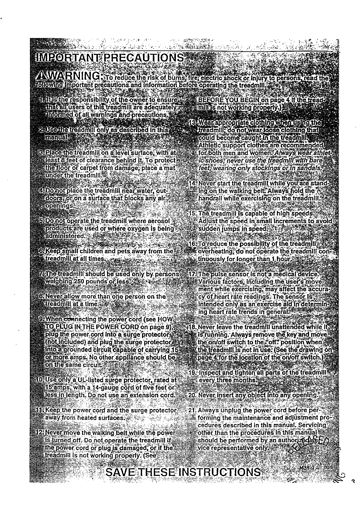
IMPORTANT PRECAUTIONS .......
o,, • • • ,t, • • •
BEFORE YOiJ BEGIN ........................
ASSEMBLY .................................
HOW TO USE THE PULSE SENSOR .............
OPERATION AND ADJUSTMENT ............ . ..
MANUAL MODE OPERATION ................... . .
HOW TO CONTROL'THE SPEED ................
HOW TO CONTROL THE INCLINE ..............
HOW TO USE THE FAT CALORIE MONITOR ....................
PROGRAM MODE OPERATION ..................................
HOW TO USE A PRESET WORKOUT PROGRAM .................
HOW TO USE THE PULSE MODE ..............................
HOW TO USE THE FAT BURN AND FAT BURN PLUS PROGFLAMS . . .
HOW TO USE THE FITNESS TEST PROGRAM ....................
• ,,• =,o Qa. OO.Q,9,,,
o= _,*•o
o• • •o
• QeO,t_ •o O,Ot,•8,••O,•••••,•Q•,,•••,O*•Q°_
• •,•°o. = , .,e°,o,°•_ooo_oo•=,,_°=5
...... .]2]]2]i........,....i.........9
• o.,=..-..e.q.t•.4o..• ole_l_ol.•el=oQ_l
............... 11
............... 11
............... 12
............... 12
.............. 12
............... la
HOW TO CREATE CUSTOM WORKOUT PROGRAMS ..................................... 16
HOW TO USE A CUSTOM WORKOUT PROGRAM ........................................ 17
TROUBLE-SHOOTING AND STORAGE ....................................................... .2.0
CONDITIONING GUIDELINES .................. . . . ,., .22.
ORDERING REPLACEMENT PARTS .......................................... .. .... . . Back Cover
Note: There Is an EXPLODED DRAWING and PART LIST attached to the center of this manual Save the
EXPLODED DRAWING and PART LIST for future reference=
*I FULL ONE YEAR WARRANTY l
For one (1) year from.the date of p_rchase, if failure occurs due to defect in material or workmanship in
this SEARS TREADMILL EXERCISER, contact the nearest SEARS See/ice Center throughoutthe
United States and SEARS will repair or replace the TREADMILL EXERCISER, free of charge.
ThLswarranty does notapply when the TREADMILL EXERCISER is used commercially or for rental pur-
poses.
This warranty gives you specJ'ficlegal dghts, and you may also have other dghts which vary from state
to state.
SEARS, ROEBUCK AND CO., DEPT• 817WA, HOFFMAN ESTATES, IL 60179
2E
BEFORE YOU BEGIN
Thank you for sel_=ctingthe IMAGE" 10.6 treadmill.
•The sophisticated IMAGE 10.6 treadmill blendsstate-
of-the-art technology with innovative designto let you
enjoy a motivating and effective form of exercise in the
convenlence and privacy of your home.
For your benefit, read this manual carefully before
using the treadmill. If you have add'dionalquestions,
please call our toll-free HELPUNE at 1-800-736-6879,
Monday thrf_ughSaturday, 7 a.m. until7 p.m. Central
Time (excluding holidays). To help us assist you,
please note the product model number and sedal num-
ber before calling. The model number of the treadmill
is 831,297562. The seda[ number can be found on a
decal attached to the treadmill (see the front cover of
this maneai for the location of the decal).
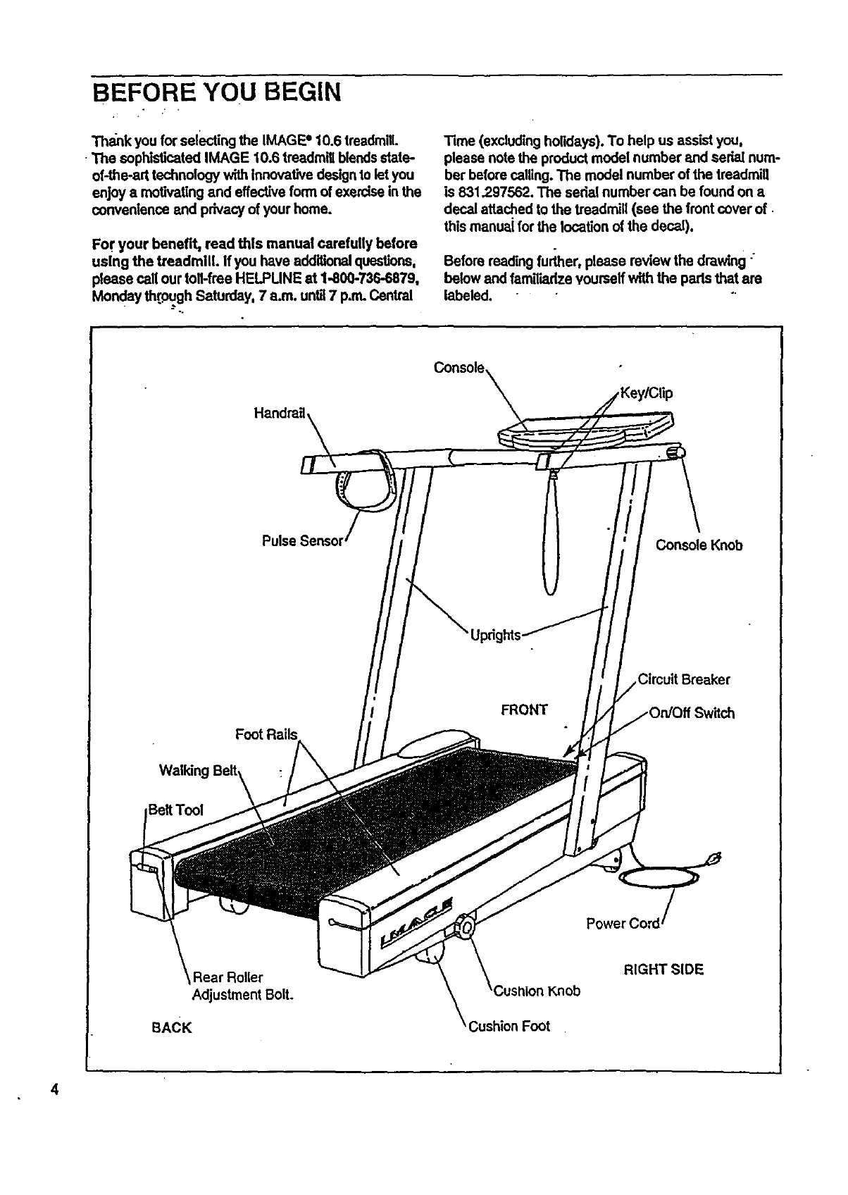
Before reading further, please review the drawing "
below and famili,'idzeyourself with the parts that are
labeled.
Console,
Handrail,
Pulse Console Knob
FRONT
Circuit Breaker
E]eltTool
Rear Roller
Adjustment Bolt.
BACK
Knob
;ushion Foot
RIGHT SIDE
4
ASSEMBLY
Assembly requires two people. Set the treadmill in a cleared area and remove all packing materials. Do not
dispose of the packing materials until the treadmill Is fully assembled.
Assembly can be completed using the Included 7/32" allen wrench _.
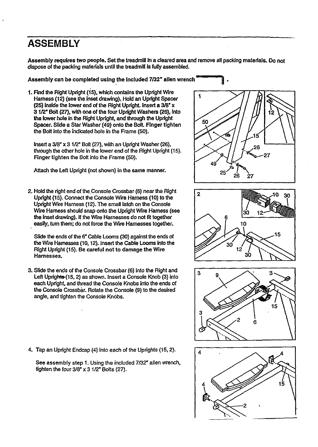
1. Find the Right Upright (15), which contains the Upright Wire
Harness (12) (sea the inset drawing), Hold an Upright Spacer
(25) Inside the lower end of the Right Upright. Insert a 3/8" x
3 1/2" Bolt (27), with one of the four Upright Washers (26), Into
the lower hola in the Right Upright, and through the Updght
Spacer. Slide aStar Washer (49) onto the Boll Finger tighten
the Bolt into the indicated hole in the Frame (50).
Insert a3/8" x 3 1/2" Bolt (27), with an Upright Washer (26),
through the other hole in the lower end of the Right Upright (15).
Finger tighten the Bolt into the Frame (50).
Attach the Left Upright (not shown) in the same manner.
7 •
26 27
2. Hold the right end of theConsole Crossbar (6) near the Right
Upright (15). Connect the Console Wire Hamess (10) to the
Upright Wire Harness (12). The small latch on the Console
W',ra Harness should snap onto the Upright Wire Hamess (see
the Inset drawing). If the Wire Harnesses do not fit together
easily,,turn them; do not force the Wire Harnesses together.
Slide the ends of the 6" Cable Looms (30) against the ends of
the Wire Harnesses (10, 12). Insert the Cable Looms into the
Right Upright (15). Be careful not to damage the Wire
Harnesses.
2
6
12 30
3. Slide the ends of the Console Crossbar (6) into the Right and
Left Updgh_e(15, 2) as shown. Insert a Console Knob (3) into
each Upright, and thread the Console Knobs into the ends of
the Console Crossbar. Rotate the Console (9) to the desired
angle, and tighten the Console Knobs.
3 9
3
15
4. Tap an Upright Endcap (4) into each of the Uprights (15, 2).
See assembly step 1. Using the included 7/32" allen wrench,
tighten the four 3/6. x 3 1/2" Bolts (27).
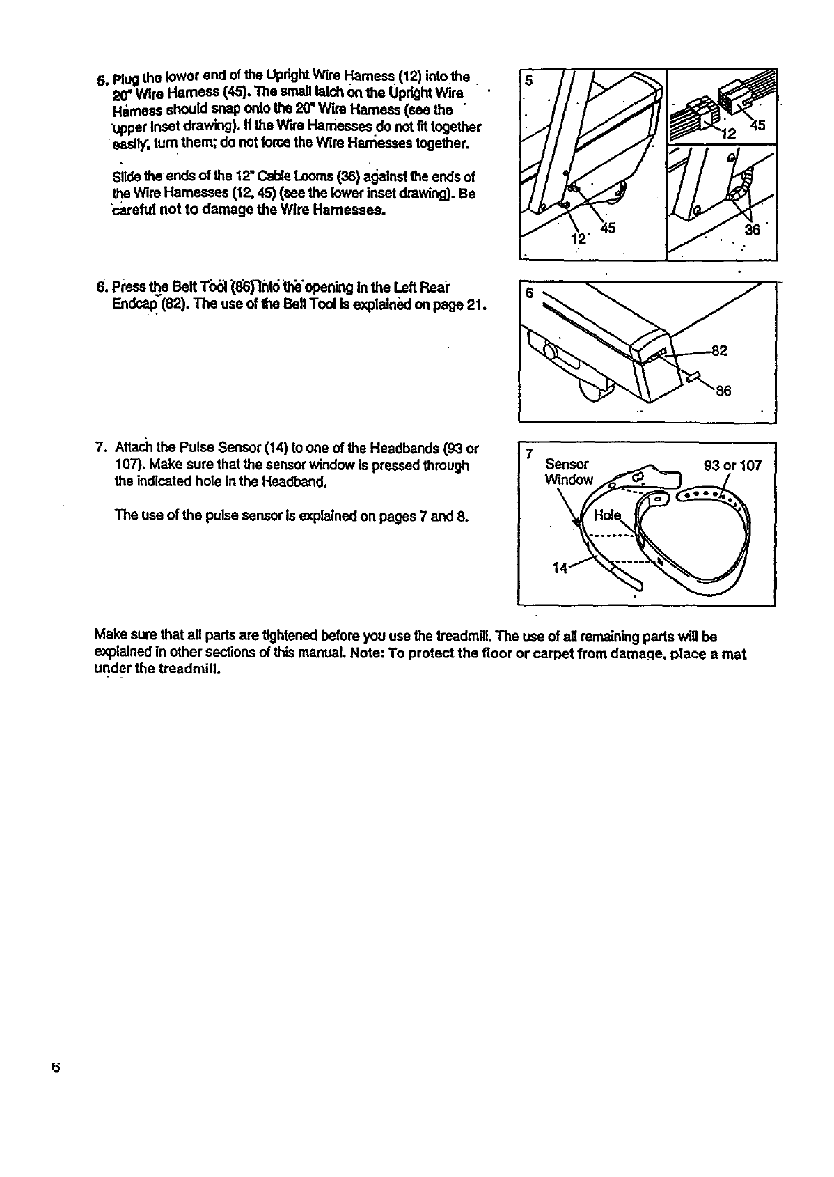
5. PlugtheIoworendoftheUprightWireHarness(12)intothe
20"WireHamese(45).Thesmaglatchonthe Uprightwire
Harness should snap onto the 20" Wire Harness (see the
upper Inset drawing), ffthe Wire Harnesses do not f_ together
easW, turn them; do not forcethe wire Harasses together.
Slide the ends of the 12"Cable Looms(36) againsttheends of
the Wire Harnesses (12, 45) (see the lower inset drawing). Be
"carefulnot to damage the Wire Harnesses.
6. Press _e Belt T'o_l(8_"mt6 _h_'opening In the Left Reai;
Endcap"(82). The use of the Belt Tool is explained on page 21.
7. Attach the Pulse Sensor (14) to one of the Headbands (93 or
107). Make sure that the sensor window is pressed through
the indicated hole in the Headband.
The use of the pulse sensor is explained on pages 7 and 8.
7Sensor
window 93 or 107
Make sure that all pads are tightened before you use the treadmill, The use of all remainingparts will be
explained in other sections of this manual. Note: To protect the floor or carpet from damage, place a mat
under the treadmill.
How TO USE THE PULSE SENSOR
The treadmill features astate-of-the-art cordlesspulse
sensor, specially designed for greater accuracy, com-
fort, and durability. Please read the following
Instructions before using the pulse sensor.
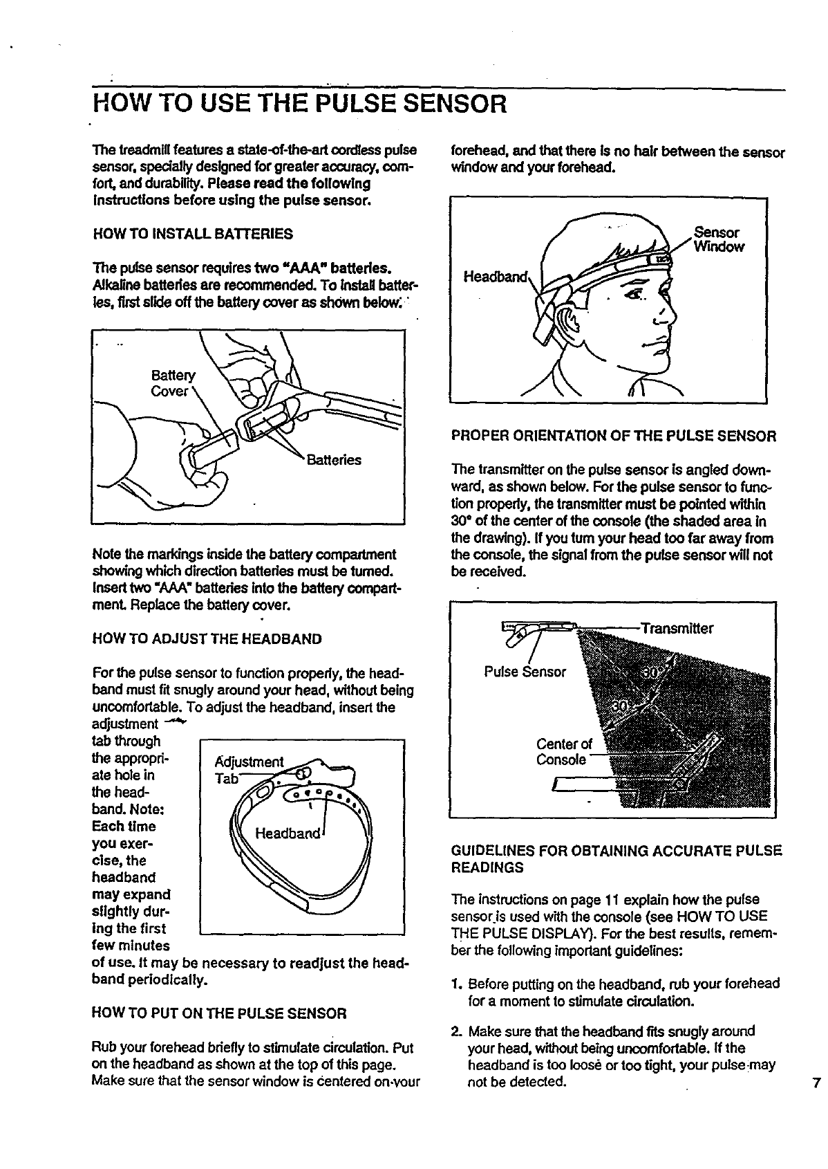
HOW TO INSTALL BATI'ERIES
The pulse sensor requires two "AAA" battedea.
Alkaline battedea are recommended. To Install batter-
lss, first slide off the batten/cover as shown below; :
\ tteries
Note the markings inside the battery compartment
showing which direction batteries must be tumed.
Insed two "AAA" batteries into the battery compart-
manL Replace the battery cover.
HOW TO ADJUST THE HEADBAND
For the pulse sensor to function properly, the head-
band must fit snugly around your head, without being
uncomfortable. To adjust the headband, insert the
adjustment
tab through
the appropri- Adjustment
ate hole in
the head-
band. Note:
Each time
you exer-
cise, the
headband
may expand
slightly dur-
Ing the first
few minutes
of use. it may be necessary to readjust the head-
band perlodlcally.
HOW TO PUT ON THE PULSE SENSOR
Rub your forehead briefly to stimulate circulation. Put
on the headband as shown at the top of this page.
Make sure that the sensor window is Centered on-your
forehead, and that there is no hair between the sensor
window and your forehead.
_ensor
Headband,
PROPER ORIENTATION OF THE PULSE SENSOR
The transmitter on the pulse sensor is angled down-
ward, as shown below. For the pulse sensor to func-
tion properly0the transmitter must be pointed within
30°of the center of the console (the shaded area in
the drawing). If you turn your head too far away from
the console, the signal from the pulse sensor wli! not
be received.
Pulse Sensor
Center of
GUIDELINES FOR OBTAINING ACCURATE PULSE
READINGS
The instructions on page 11 explain how the pulse
sensor is used with the console (see HOW TO USE
THE PULSE DISPLAY). For the best results, remem-
ber the following important guidelines:
1. Before putting on the headband, rub your forehead
for a moment to stimulate circulation.
2. Make sure that the headband fits snugly around
your head, withoutbeing uncomfortable. If the
headband is too loose or too tight, your pulse-may
not be detected. 7
f
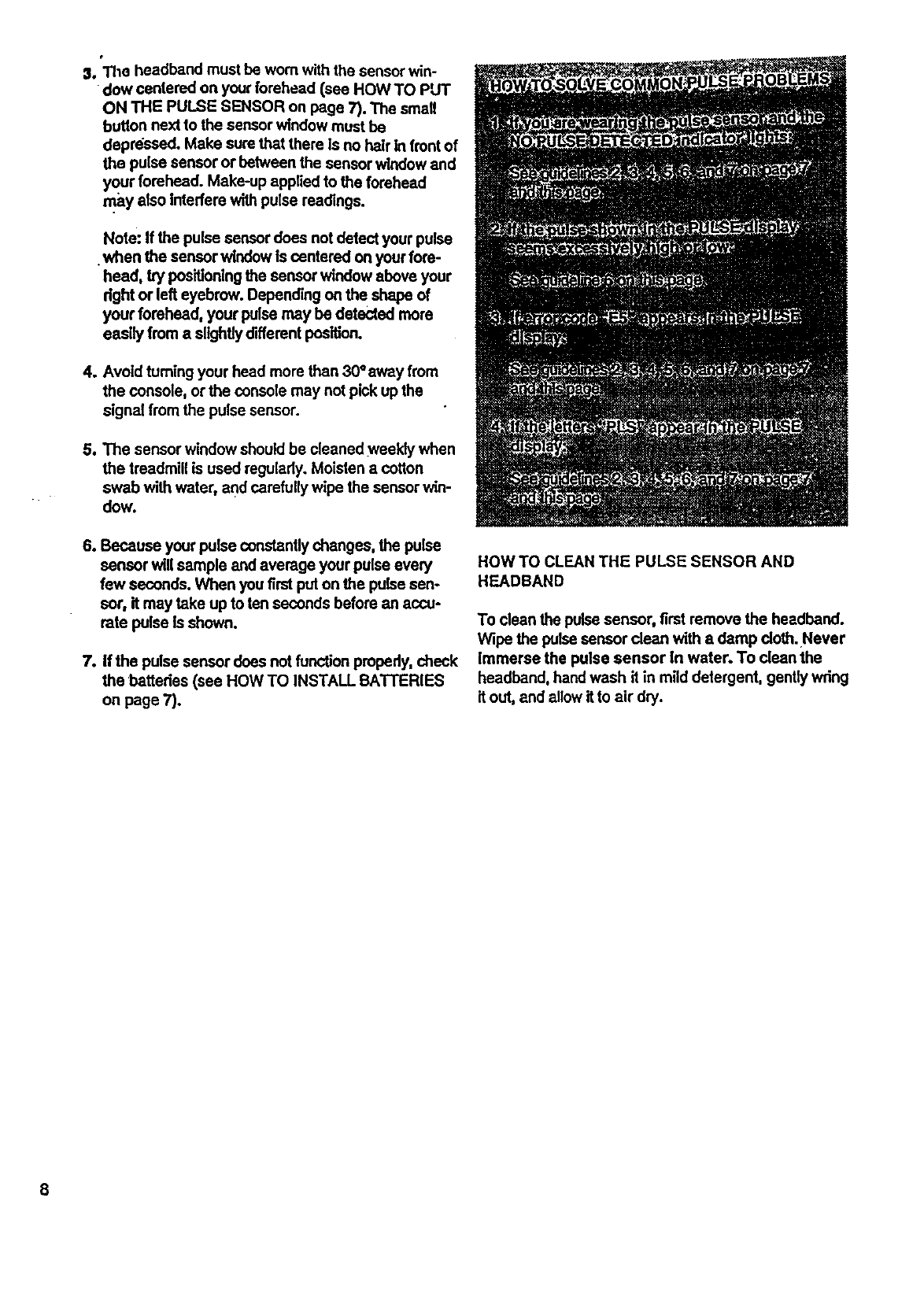
01.The headband must be worn with the sensor win-
dow centered on your forehead (see HOW TO PUT
ON THE PULSE SENSOR on page 7). The small
button next to the sensor window must be
depressed. Make sure that there Is no hair In front of
the pulse sensor or between the sensor window and
your forehead. Make-up applied to the forehead
may also Interfere withpulse readings.
Note: If the pulse sensor does not detect your pulse
•when the sensor windowis centered on your fore-
heed, try positioningthe sensor window above your
right or left eyebrow. Depending on the shape of
your forehead, your pulse may be detected more
easily from a slightly different position.
4. Avoid turning your head more than 30°away from
the console, or the console may not pick up the
signal from the pulse sensor.
5. The sensor window should be cleaned weekly when
the treadmill is used regularly. Moisten a cotton
swab with water, and carefully wipe the sensor win-
dow.
6. Because your pulse constantlychanges, the pulse
sensor will sample and average your pulse every
few seconds. When you first put on the pulse sen-
sor, it may take up to ten seconds before an accu-
rate pulse Is shown.
7. If the pulse sensor does not function properly, check
the batteries (see HOW TO INSTALL BATTERIES
on page 7).
HOW TO CLEAN THE PULSE SENSOR AND
HEADBAND
To clean the pulse sensor, first remove the headband.
Wipe the pulse sensor dean with a damp cloth.Never
Immerse the pulse sensor In water. To dean the
headband, hand wash it in mild detergent, gently wring
it out, and allow it to air dry.
8
OPERATION AND ADJUSTMENT
THE PERFORMANT LUBE TM WALKING BELT
Your treadmill features awalking belt coated with
PERFORMANT LUSETM, a high-performance lubricant.
IMPORTANT: Never apply silicone spray or other
substances to the walking belt or the walldng plat-
form. They will deteriorate the walking belt end
cause excessive wear.
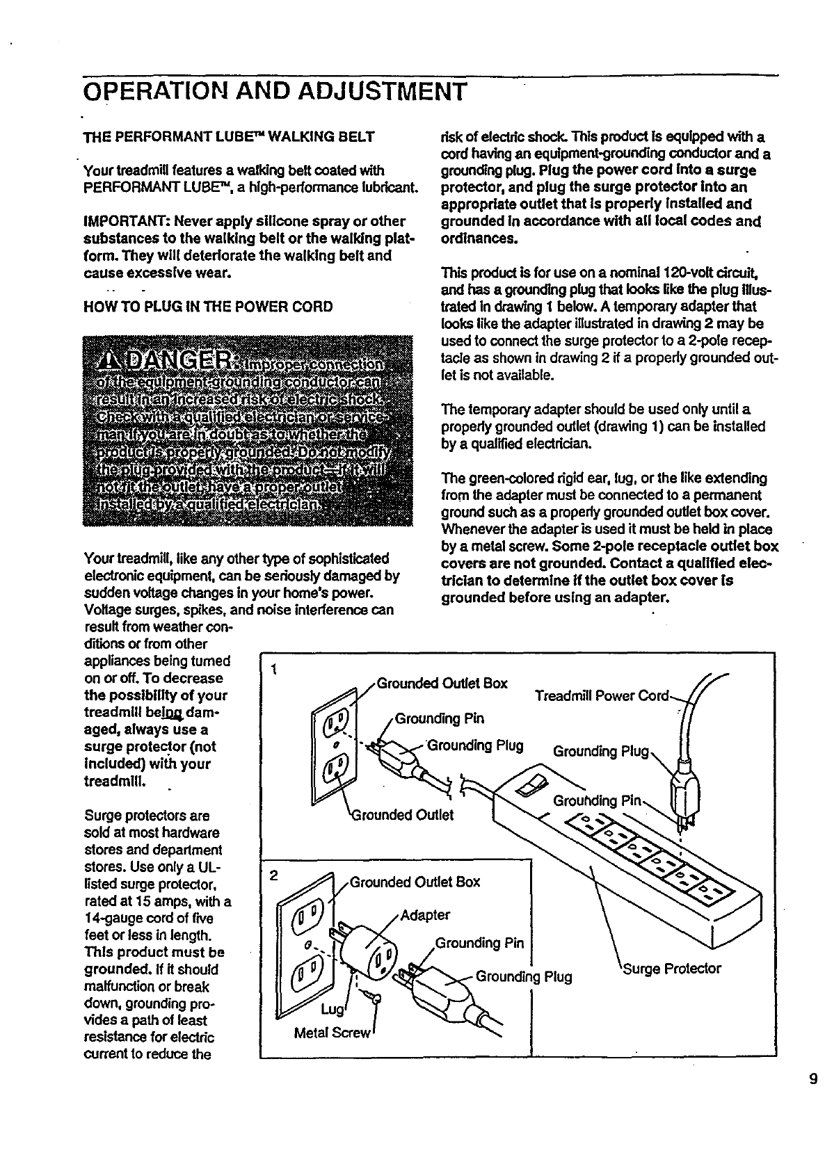
HOW TO PLUG IN THE POWER CORD
risk of electric shock, This product is equipped with a.
cord having an equlpment-grounding conductor and a
grounding plug. Plug the power cord into asurge
protector, and plug the surge protector into an
appropriate outlet that Is properly Installed and
grounded in accordance with all local codes and
ordinances.
This product is for use on a nominal 120-volt circuit,
and has agrounding plug that looks like the plug Illus-
trated in drawing 1 below. A temporary adapter that
locks like the adapter illustrated in drawing 2 may be
used to connect the surge protector to a 2-pole recep-
tacle as shown in draw',ng2 if a properly grounded out-
let is not available.
The temporary adapter should be used only until a
properly grounded outlet (drawing 1) can be installed
by aqualified electrician.
Your treadmill, like any other type of sophisticated
electronic equipment, can be seriously damaged by
sudden voltage changes in your home's power.
Voltage surges, spikes, and noise interference can
result from weather con-
ditions or from other
appliances being turned 1
on or off. To decrease
the possibility of your
treadmill belg._ dam-
aged, always use a
surge protector (not
Included) with your
treadmlll.
Surge protectors are
sold at most hardware
stores and department
stores. Use only a UL-
listed surge protector,
rated at 15 amps, with a
14-gauge cord of rNe
feet or less in length.
Thls product must be
grounded. If it should
malfunction or break
down, grounding pro-
vides a path of least
resistance for electdc
current to reduce the
The green-colored dgid ear, lug, or the like extending
from the adapter must be connected to a permanent
ground such as a properly grounded outlet box cover.
Whenever the adapter is used it must be held in place
by a metal screw. Some 2-pole receptacle outlet box
covers are not grounded. Contact aqualified elec-
trician to determine If the outlet box cover is
grounded before using an adapter.
Grounded Outlet Box
/Adapter
_.. ;_/_ __Grounding Pin
_L'u g_'_ _°_/_u ndii g
Metal Screw _J
Treadmill Power Cord--.
Grounding
Plug 'Surge Protector
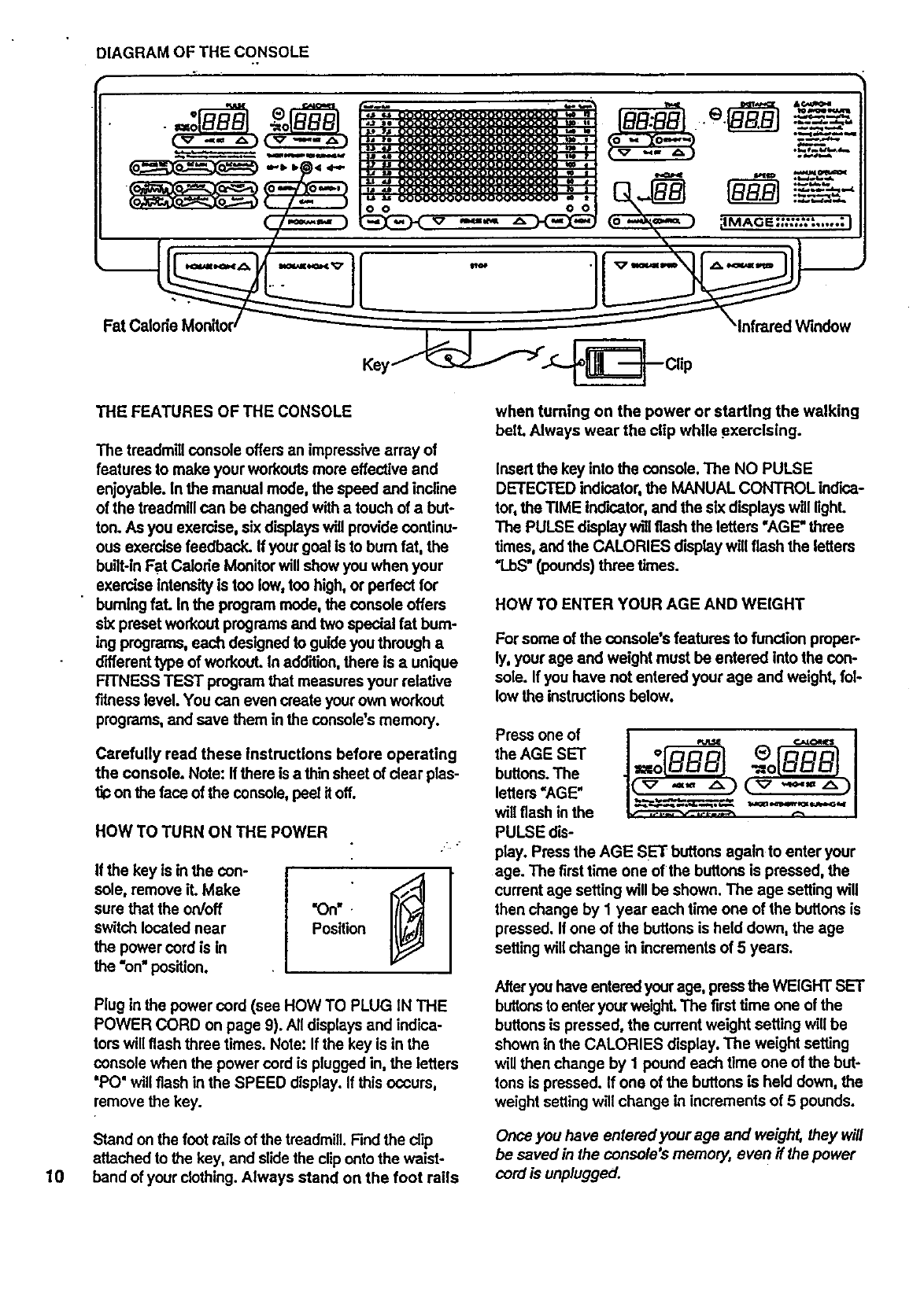
DIAGRAM OF THE CONSOLE
Fat (
10
THE FEATURES OF THE CONSOLE
The treadmill console offersan impressivearray of
features to make your workouts more effective and
enjoyable. In the manual mode, the speed and incline
of the treadmill can be changed with a touch of abut-
ton. As you exercise, six displayswill provide continu-
ous exercise feedback. If your goal is to bum fat, the
built-in Fat Calode Monitor will show you when your
exercise intensityis too low, ton high, or perfect for
burning fat. In the program mode, the console offers
six preset workout programs and two special fat bum-
ing programs,each designed to guide you through a
different type of workout. In addition,there is aunique
FITNESS TEST program that measures your relative
fitness level. You can even create your own workout
programs, and save them in the console's memory.
Carefully read these Instructions before operating
the console. Note: If there is a thin sheet of clear pies-
on the face of the console,peel it off.
HOW TO TURN ON THE POWER
If the key is in the con-
sole, remove it. Make
sure that the on/off
switch located near
the power cord is in
the "on" position.
•_On w .
Position
Plug in the power cord (see HOW TO PLUG iN THE
POWER CORD on page 9). All displaysand indica-
tors will flash three times. Note: If the key is in the
console when the power cord is plugged in, the letters
"PO" will flash in the SPEED display. If this occurs,
remove the key.
Stand on the foot rails of the treadmill. Findthe dip
attached to the key, and slide the cliponto the waist-
band of your clothing. Always stand on the foot rails
when turning on the power or starting the walking
bell Always wear the clip while exercising.
Insert the key into the console. The NO PULSE
DETECTED indicator, the MANUAL CONTROL indica-
tor, the TIME Ind'_.ator,and the six displays will light.
The PULSE displaywill f_sh the letters "AGE" three
times, and the CALORIES display will flash the letters
'l.bS" (pounds) three times.
HOW TO ENTER YOUR AGE AND WEIGHT
For some of the console's features to function proper-
ly,your age and weight must be entered into the con-
sole. If you have not entered your age and weight, fol-
lowthe instructionsbelow.
Press one of
the AGE SET
buttons.The
letters=AGE"
will flash in the
PULSE dis-
play. Press the AGE SET buttons again to enter your
age. The first time one of the buttons is pressed, the
current age setting will be shown. The age setting will
then change by I year each time one of the buttons is
pressed. If one of the buttons is held down, the age
setting will change in increments of 5 years.
Afteryou have entered your age, pressthe WEIGHT SET
buttonstoenteryour weight.The first time one of the
buttons is pressed, the current weight setting will be
shown in the CALORIES display. The weight setting
will then change by 1 pound each time one of the but-
tons is pressed. If one of the buttonsis held down, the
weight setting will change in increments of 5 pounds.
Once you have entered your age and weight, they will
be saved in the console's memory, even if the power
cord is unplugged.
MANUAL MODE OPERATION
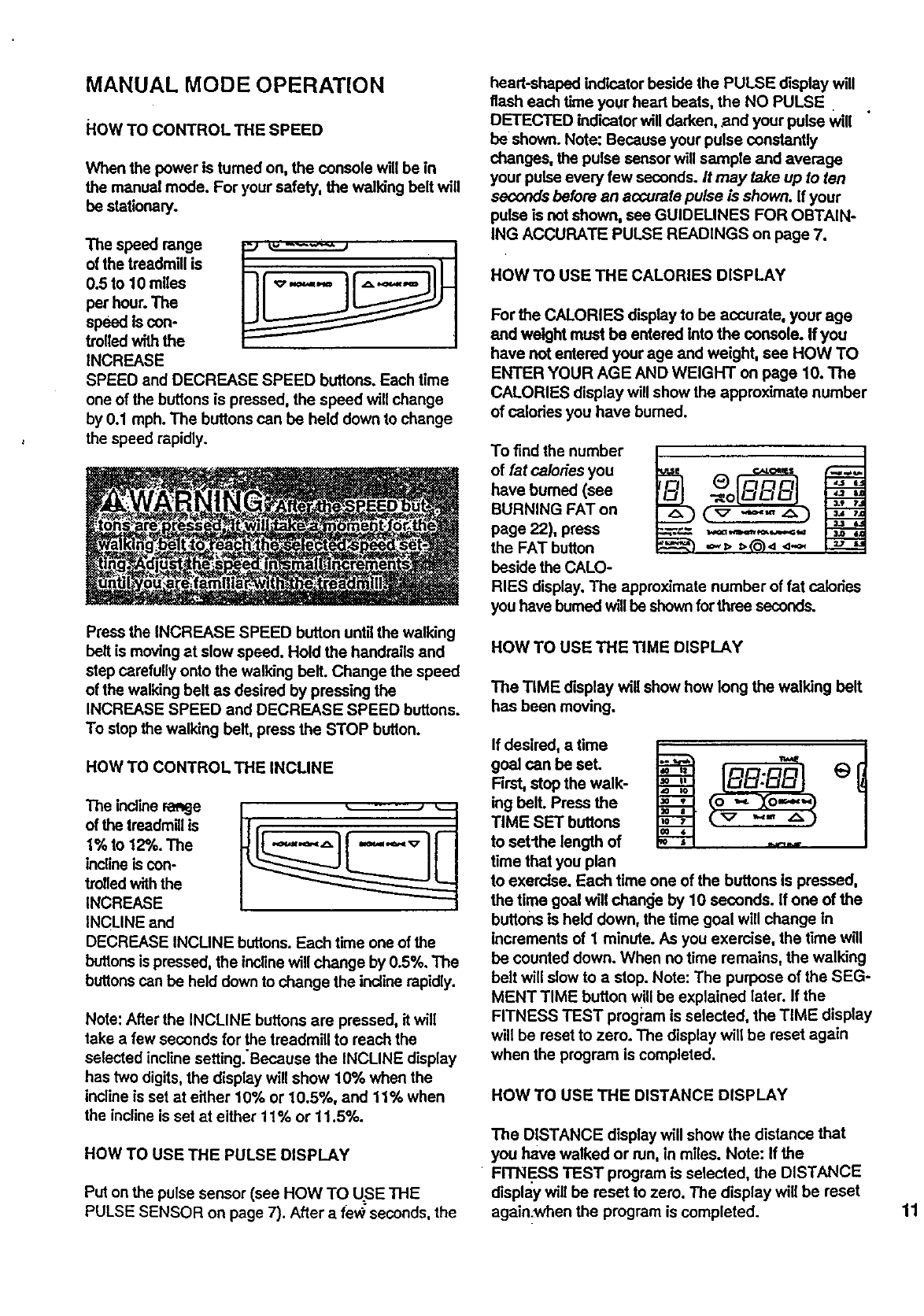
HOW TO CONTROL THE SPEED
When the power is turned on, the console will be in
the manual mode. For your safety, the walking belt will
be stationary.
The speed range
of the treadmill is
0.5 to 10 miles
per hour. The
speed is con-
trolled with the
INCREASE
SPEED and DECREASE SPEED buttons. Each time
one of the buttons is pressed, the speed will change
by 0.1 mph. The buttons can be held down to change
the speed rapidly.
Press the INCREASE SPEED button until the walking
belt is moving at slow speed. Hold the handrails and
step carefully onto the walking belt. Change the speed
of the walking belt as desired by pressing the
INCREASE SPEED and DECREASE SPEED buttons.
To stop the walking belt, press the STOP butlon.
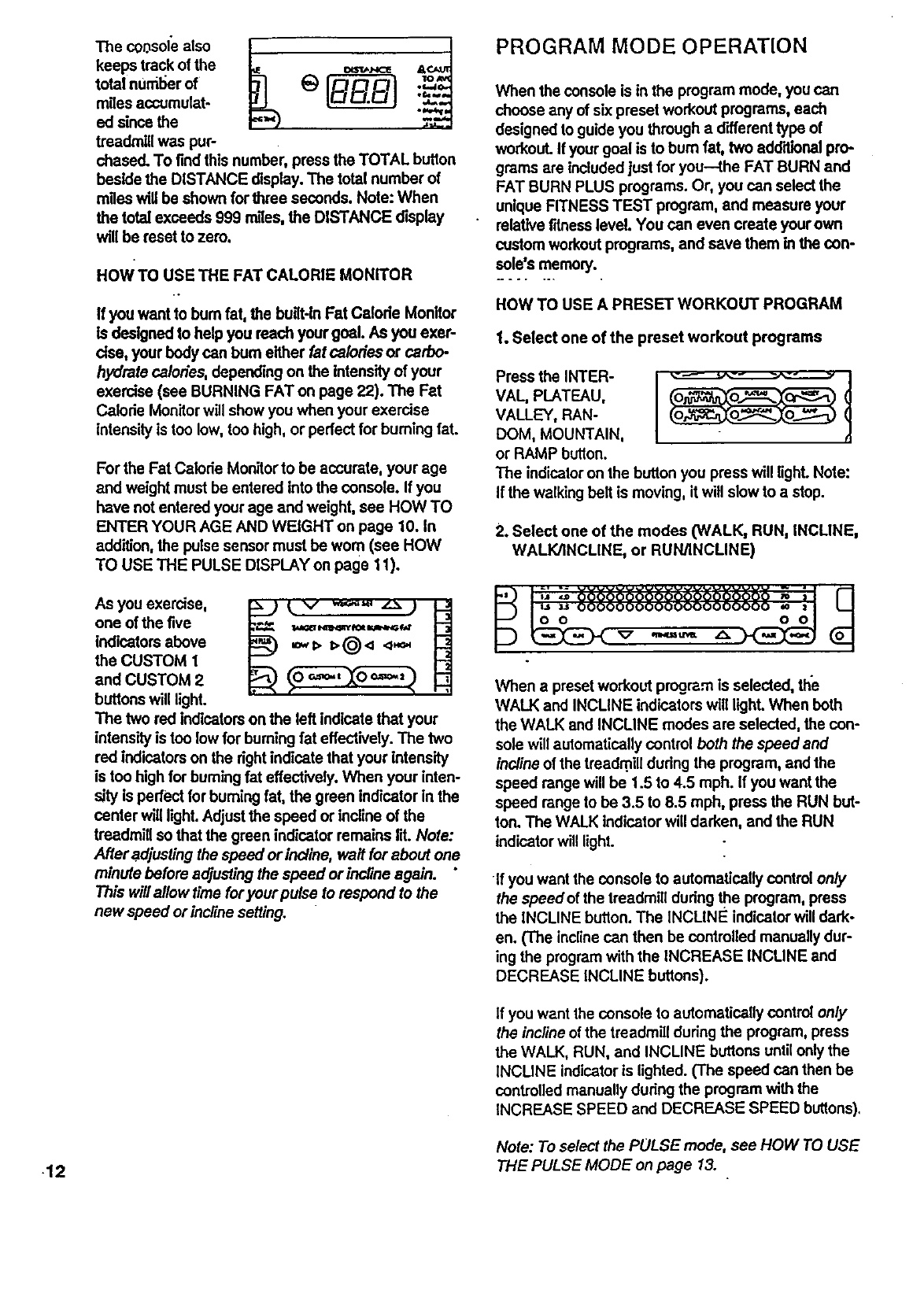
HOW TO CONTROL THE INCLINE
The incline range
of the treadmill is
1% to 12%. The
inclineis con-
trolled withthe
INCREASE
INCLINE and
DECREASE INCLINE buttons. Each time one of the
buttonsis pressed, the incline will change by 0.5%. The
buttonscan be held down to change the incline rapidly.
Note: After the INCLINE buttons are pressed, it will
take a few seconds for the treadmill to reach the
o
selected incline setting. Because the INCLINE display
has two digits, the display will show 10% when the
incline is set at either 10% or 10.5%, and 11% when
the incline is set at either 11% or 11.5%.
HOW TO USE THE PULSE DISPLAY
Put on the pulse sensor (see HOW TO USE THE
PULSE SENSOR on page 7). After a fev;,seconds, the
heart-shaped ind'matorbeside the PULSE display will
flash each time your heart beats, the NO PULSE
DETECTED indicator will darken, and your pulse will
be shown. Note: Because your pulse constantly
changes, the pulse sensor will sample and average
your pulse every few seconds. It may take up to ten
seconds before an accurafe pulse is shown. If your
pulse is not shown, see GUIDEUNES FOR OBTAIN-
ING ACCURATE PULSE READINGS on page 7.
HOW TO USE THE CALORIES DISPLAY
For the CALORIES display to be accurate, your age
and weight must be entered into the console, ff you
have not entered your age and weight, see HOW TO
ENTER YOUR AGE AND WEIGHT on page 10. The
CALORIES display will show the approximate number
of calodes you have burned.
To find the number
of fat calories you
have burned (see
BURNING FAT on
page 22), press
the FAT button
beside the CALO-
RIES display. The approximate number of fat calories
you have burnedwill be shown forthree seconds.
HOW TO USE THE TIME DISPLAY
The TIME display will show how long the walking belt
has been moving.
If desired, atime
goal can be set.
Rrst, stop the walk-
ing bell Press the
TIME SET buttons
to setlhe length of
time that you plan
O
to exercise. Each time one of the buttons is pressed,
the time goal wlil chan_e by 10 seconds. If one of the
buttons is held down, the time goal will change in
increments of 1 minute. As you exercise, the time will
be counted down. When no time remains, the walking
belt will slow to a stop. Note: The purpose of the SEG-
MENT TIME button will be explained later. If the
FITNESS TEST prog_'amis selected, the TIME display
will be reset to zero. The display will be reset again
when the program is completed.
HOW TO USE THE DISTANCE DISPLAY
The DISTANCE display will show the distance that
you have walked or run, in miles. Note: If the
FITNI_SS TEST program is selected, the DISTANCE
display will be reset to zero. The display will be reset
again.when the program is completed. 11
keeps track of the =s_._,c_ a
total nUml_erof _) ._
-_,-
miles accumulat-
ed since the
treadmill was pup
chased. To find this number, press the TOTAL button
beside the DISTANCE display. The total number of
miles will be shown for three seconds. Note: When
the total exceeds 999 r_les, the DISTANCE display
will he reset to zero.
HOW TO USE THE FAT CALORIE MONITOR
ff you want to bum fat, the built-inFat Calode Monitor
Is designed to help you reach your goal. As you exer-
cise, your body can bum either fat calodes or carbo-
hydrate calories, depending on the intensity of your
exercise (see BURNING FAT on page 22). The Fat
Calode Monitor will show you when your exercise
intensityis too low, too high, or perfect for bumiog fat.
For the Fat Calorie Monitorto be accurate, your age
and weight must be entered into the console. If you
have not entered your age and weight, see HOW TO
ENTER YOUR AGE AND WEIGHT on page 10. In
addition, the pulse sensor must be worn (see HOW
TO USE THE PULSE DISPLAY on page 11).
As you exercise,
one of the five
indicatorsabove
the CUSTOM 1
and CUSTOM 2
buttonswill light.
_.v ,,_-,,*, z.._ )
'tA_GEIINqNlUlt fOI N t_i'
The two red indicatorson the left indicate that your
intensityis too low for burning fat effectively. The two
red indicatorson the rightindicate that your intensity
is too highfor burning fat effectively. When your inten-
sity is perfect for burning fat, the green indicator in the
center will light. Adjust the speed or incline of the
treadmill so that the green indicator remains lit. Note:
After adjustingthe speed or incline, wait for about one
minute before adjustingthe speed or incline again.
This will allow time for your pulse lo respond to the
new speed or incEnesefting.
PROGRAM MODE OPERATION
When the console is in the program mode, you can
choose any of six preset workout programs, each
designed to guideyou through adifferent type of
workout. If your goal is to bum fat, two edd'rlional pro-
grams are includedjust for you--the FAT BURN and
FAT BURN PLUS programs. Or, you can select the
unique FITNESS TEST program, and measure your
relative fitnesslevel. You can even create your own
customworkoutprograms, and save them in the con-
sole's memory.
HOW TO USE A PRESET WORKOUT PROGRAM
1. Select one of the preset workout programs
Press the INTER- I
VAL, PLATEAU,
VALLEY, RAN-
DOM, MOUNTAIN,
or RAMP button.
The indicator on the button you press will light. Note:
If the walkingbelt is moving, it will slow to astop.
2oSelect one of the modes (WALK, RUN, INCUNE,
WALK/INCLINE, or RUN/INCLINE)
When a presetworkout program is selected, the
WALK and INCLINE indicatorswill light. When both
the WALK and INCLINE modes are selected, the con-
sole will automatically control both the speed and
incline of the treedm,ill dudng the program, and the
speed range will be 1.5 to 4.5 mph. If you want the
speed range to be 3.5 to 8.5 mph, press the RUN but-
ton. The WALK indicatorwill darken, and the RUN
indicatorwill light.
If you want the console to automatically control only
the speedof the treadmill dudng the program, press
the INCLINE button. The INCLINE indicatorwill dark-
en. (The inclinecan then be controlled manuallydur-
ing the program with the INCREASE INCUNE and
DECREASE INCLINE buttons).
If you want the console to automatically control only
the incline of the treadmill duringthe program, press
the WALK, RUN, and INCLINE buttons untilonly the
iNCLINE indicator is lighted. (The speed can then be
controlled manually duriog the program with the
INCREASE SPEED and DECREASE SPEED buttons).
Note: To select the PULSE mode, see HOW TO USE
•12 THE PULSE MODE on page 13.
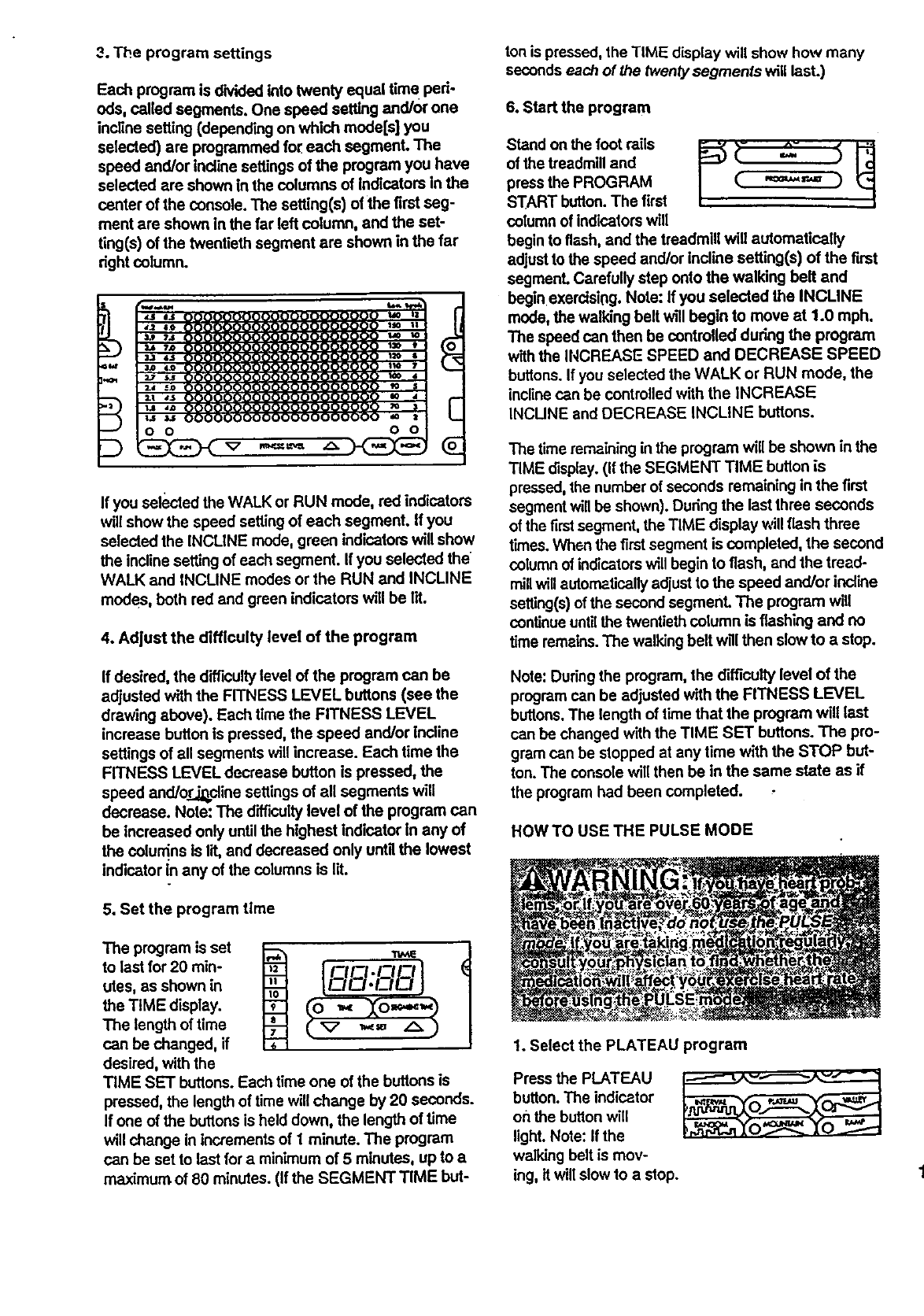
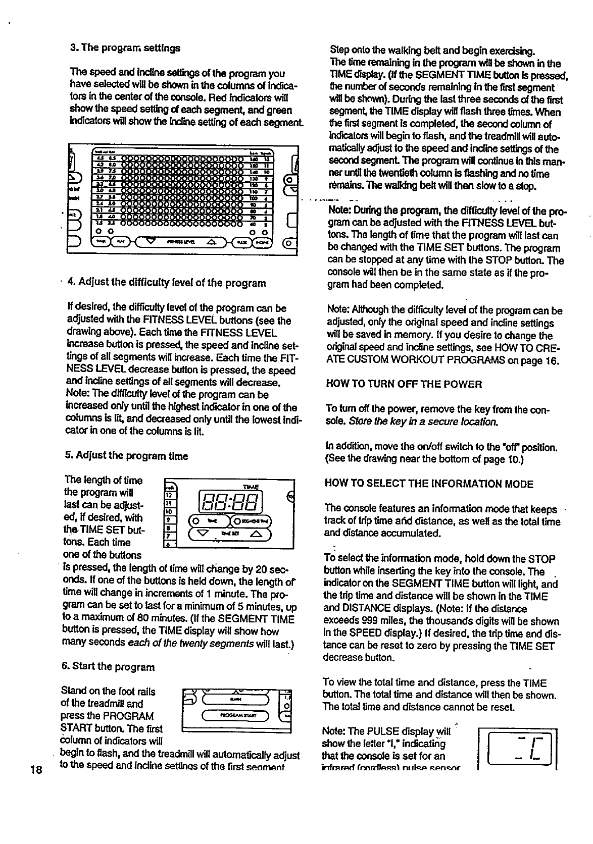
3. The program settings
Each program is divided into twenty equal time ped-
eds, called segments. One speed setting and/or one
incline setting (depending on which models] you
selected) are programmed for each segment. The
speed and/or Indine settings of the program you have
selected are shown in the columns of indicators In the
canter of the console. The setting(s) of the first seg-
ment are shown in the far left column, and the set-
ting(s) of the twentieth segment are shown in the far
dght column.
If you selected the WALK or RUN mode, red indicators
will show the speed setting of each segmanL If you
selected the INCLINE mode, green indicatorswill show
the Incline setting of each segment. If you selected the
WALK and INCLINE modes or the RUN and INCLINE
modes, both red and green indicators will be lit.
4. Adjust the di_culty level of the program
If desired, the difficultylevel of the program can be
adjusted with the FITNESS LEVEL buttons (see the
drawing above). Each time the FITNESS LEVEL
increase butJonIs pressed, the speed and/or Incline
settings of all segments will increase. Each time the
FITNESS LEVEL decrease button is pressed, the
speed andior.._dine settings of all segments will
decrease. Note: The difficultylevel of the program can
be increased only untilthe highest indicator in any of
the colun'_ns is lit, and decreased only untg the lowest
indicator in any of the columns is lit.
5. Set the program time
The program is set
to last for 20 min-
utes, as shown in
the TIME display.
The length of time
can be changed, if
desired, with the
Irz!FZl.r-Icl I
TIME SET buttons. Each time one of the buttons is
pressed, the length of time will change by 20 seconds.
If one of the buttonsis held down, the length of time
will change in increments of I minute. The program
can be set to last fora minimum of 5 minutes, up toa
maximum of 80 minutes. (If the SEGMENT TIME but-
ton is pressed, the TIME display will show how many
seconds each of the Iwentysegments will last.)
6. Start the program
Stand on the foot rails _ _- _- _ _._
of the treadmill and
press the PROGRAM | (.' .'=='.-,'.'= )
/
START button. The first /
column of indicators will
begin to flash, and the treadmill will automatically
adjust to the speed and/or incline setting(s) of the first
segment. Carefully step onto the walking belt and
begin exercisir=g.Note: If you selected the INCLINE
mode, the walking belt will begin to move at 1.0 mph.
The speed can then be controlled during the program
with the INCREASE SPEED and DECREASE SPEED
buttons. If you selected the WALK or RUN mode, the
incline can be controlled with the INCREASE
INCUNE and DECREASE INCLINE buttons.
The time remaining inthe program will be shown in the
TIME display. (If the SEGMENT TIME button is
pressed, the number of seconds remaining in the first
segmentwill be shown). During the last three seconds
of the first segment, the TIME display will flash three
times. When the firstsegment is completed, the second
column of indicatorswill begin to flash, and the tread-
millwill automatically adjust to the speed and/or incline
setting(s)of the second segment. The program will
continue untilthe twentieth column is flashing and no
time remains.The walking belt will then slow to a stop.
Note: Duringthe program, the difficulty level of the
program can be adjusted with the FITNESS LEVEL
buttons. The length of time that the program will last
can be changed with the TIME SET buttons. The pro-
gram can be stopped at any time with the STOP but-
ton. The console will then be in the same state as if
the program had been completed.
HOW TO USE THE PULSE MODE
1. Select the PLATEAU program
Press the PLATEAU --.---.-_ ._-_------ "-'-- -
button. The indicator
on the buttonwill
light. Note: If the
wa/Idng belt is mov-
ing, it will slow to a stop. 1:

2. Select the PULSE mode
Press the PULSE button. The PULSE indicatorwill
light, and the WALK, RUN and INCLINE indicators will
darken.
Whenthe
PULSEmode
isselected,
theletters
"AGE"will
flash inthe
PULSE display, and the letters "LbS"will flash in the
CALORIES display. If you have not entered your age
and weight into the console, see HOW TO ENTER
YOUR AGE AND WEIGHT on page 10. If you have
already entered your age and weight, simply press
one of the AGE SET buttons, and then press one of
the WEIGHT SET buttons.
3. Put on the pulse sensor
onlyuntilthe lowest indicatorin one of the columnsis
In addition, there may be a limit to how far the diffi-
cu#y level can be adjusted depending on your age.
6. Set the program time
The program is
set to last for,20
minutes,aS shown
in the TIME dis-
play. The program
can be set to last
for differentlength
Co Xo- -9
.=, A)
of time, if desired, with the TIME SET buttons. Each
time one of the buttons is pressed, the length of time
will change by 20 seconds. If one of the buttonsis
held down, the length of time will dnange in incre-
ments of 1 minute. The pmgrem can be set to last for
aminimumof 20 minutes, up to a maximum of 80
minutes. (If the SEGMENT TIME button is pressed,
the TIME display will show how many seconds each
of the twenty segments will last.)
See HOW TO USE THE PULSE DISPLAY on pege 11. 7. Start the program
14
4. The program settings
Each program is divided into twenty equal time ped-
ods, called segments. One pulse setting is pro-
grammed for each segmenL The pulse settings of the
program you have selected are shown in the columns
of indicatorsin the center of the console. Red indica-
tom will show the pulse setting of each segment.
o O
]
5. Adjust the difficulty level of the program
_f desired, the difficulty level of the pmgrem can be
_djusted with the FITNESS LEVEL buttons (see the
,::rewing above). Each time the FITNESS LEVEL
!_crease button is pressed, the pulse settings of all
s,.'gments will increase. Each time the FITNESS
LL:'VELdecrease buttonis pressed, the pulse settings
ot ._ilsegments will decrease. Note: The difficultylevel
•x)f_ program can be increased only untilthe highest
indicatorin one of the columnsis lit, and decreased
Stand on the foot rails ri- =_- _ _
of the treadmill and
press the PROGRAM ( "=""1" )
START button. The first
column of indicators will
begin to flash. When the walking belt begins to move,
carefully step onto the walking belt and begin exercis-
ing. The console will automatically change the speed
and/or incline of the treadmill at any time to keep your
pulse near the setting of the firstsegment. The SPEED
or INCUNE display will flash three times to warn you
each time the spe_t or incline is about to change.
•The time remaining in the program will be shown in
the TIME display. (If the SEGMENT TIME buttonis
pressed, the number of seconds remaining in the cur-
rent segment will be shown). During the last three
seconds of the first segment, the TIME display will
flash three times. When the firstsegment is completed,
the second column of indicatorswill begin to flash. The
console will then change the speed and/or incline of
the treadmill at any time to keep your pulse near the
setting of the second segment. The program will con-
finue untilthe twentieth column is flashing, and no
time remains. The walking belt will then slow to a stop.
Note: Dudng the program, the difficulty level of the
program can be adjusted with the FITNESS LEVEL
buttons. The spee_:lof the treadmill can be changed
•withthe INCREASE SPEED and DECREASE SPEED
buttons. The incline of the treadmill can be changed
with the INCREASE INCLINE and DECREASE
INCLINE buttons. However, ff you increase the speed,
the incline will automatically decrease; if you dec[ease
the speed, the incline will automaUcally Increase. The
console will always attempt to keep your pulse near
the setting of the current segmenL If your pu;se is not
detected for one minute, the speed of the treadmill will
automatically decrease by half. If your pulse is not
detected for asecond minute, the speed will decrease
by half again. If your pulse is not detected for three
minutes, the walking belt will slow to astop. The pro-
gram can be stopped at any time with the STOP but-
ton. The console will then be in the same state as if.
the program had been completed.
HOWTO USE THE FAT BURN AND FAT BURN
PLUS PROGRAMS
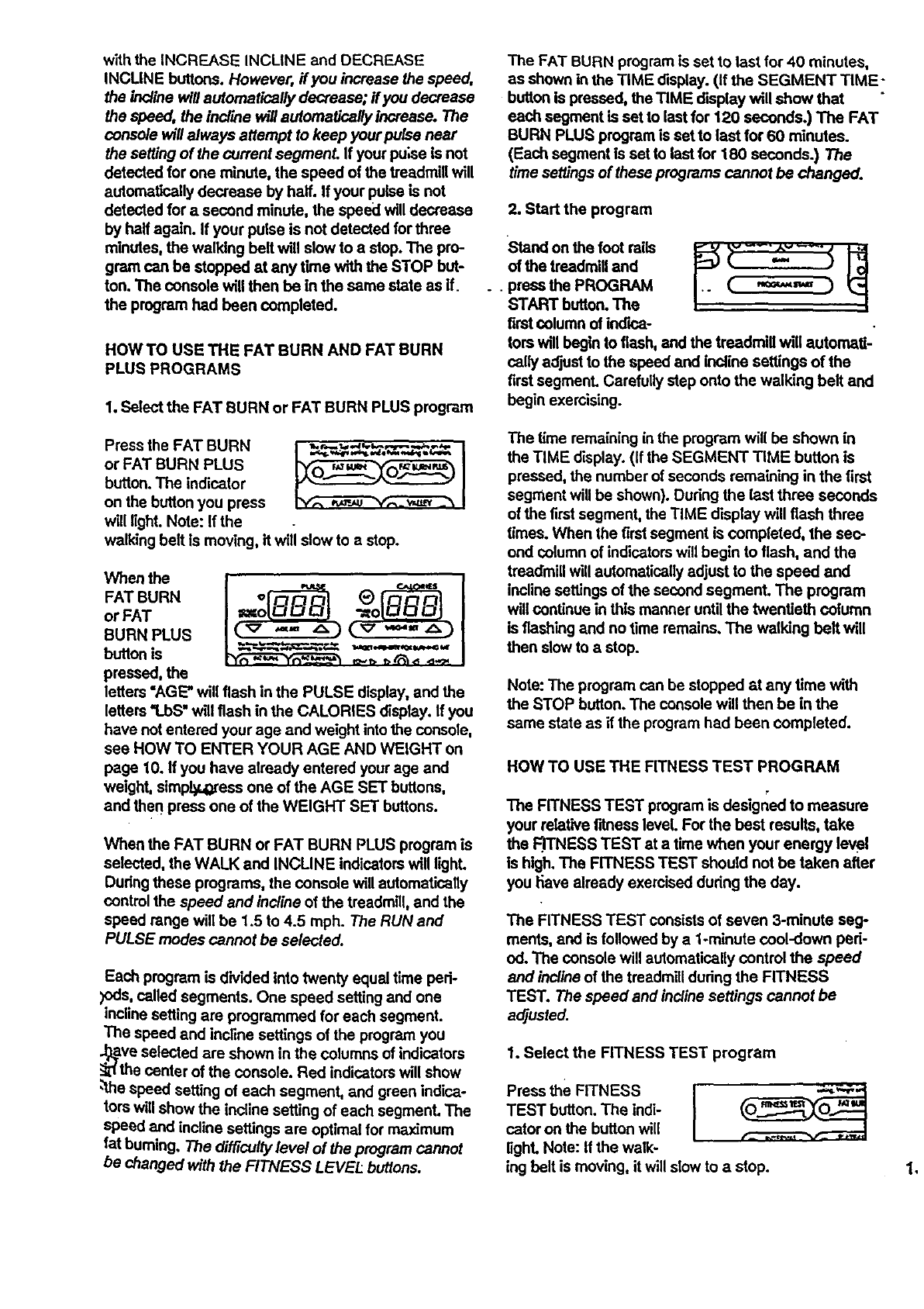
1. Select tbe FAT BURN or FAT BURN PLUS program
Press the FAT BURN _I
or FAT BURN PLUS
button. The indicator
on the button you press
will light. Note: If the
walking belt is moving, it will slow to a stop.
When the
FAT BURN
or FAT
BURN PLUS
button is
pressed, the
letters "AGE" will flash in the PULSE display, and the
letters '1.bS" will flash in the CALORIES display. If you
have notentered your age and weight into the console,
see HOW TO ENTER YOUR AGE AND WEIGHT on
page 10. If you have already entered your age and
weight, simpi_,oress one of the AGE SET buttons,
and then press one of the WEIGHT SET buttons.
W'nen the FAT BURN or FAT BURN PLUS program is
selected, the WALK and INCUNE indicators will light.
Dudng these programs, the console will automatically
control the speed and incline of the treadmill, and the
speed range will be 1.5 to 4.5 mph. The RUN and
PULSE modes cannot be selected.
Each program is dMded into twenty equal time ped-
)ods, called segments. One speed setting and one
incline setting are programmed for each segment.
The speed and incline settings of the program you
J_ve selected are shown in the columns of indicators
_'_the center of the console. Red indicators will show
,'the speed setting of each segment, and green indica-
tors will show the incline setting of each segment. The
speed and incline settings are optimal for maximum
fat burning. The difficully level of the program cannot
be Changed with the FITNESS LEVEl: buttons.
The FAT BURN program is set to last for 40 minutes,
as shown in the TIME display. (If the SEGMENT TIME-
button Is pressed, the TIME display will show that
each segment is set to last for 120 seconds.) The FAT
BURN PLUS program is set to last for 60 minutes.
(Each segment is set to last for 180 seconds.) The
time settings of these programs cannot be changed.
2. Start the program
Stand on the foot rails .,
of the treadmill and
• press the PROGRAM
START button. The
firstcolumn of iedica-
tors will begin to flash, and the treadmill will automaft-
sally adjust to the speed and incline settings of the
first segmenL Carefully step onto the walking belt and
begin exercising.
The time remaining in the program will be shown in
the TIME display. (If the SEGMENT TIME button is
pressed, the number of seconds remaining in the first
segment will be shown). During the last three seconds
of the first segment, the TIME display will flash three
times. When the first segment is completed, the sec-
ond column of indicatorswill begin to flash, and the
treadmill will automatically adjust to the speed and
incline settings of the second segment. The program
will continue in this manner until the twentieth column
is flashing and no time remains. The walking belt will
then slow to astop.
Note: The program can be stopped at any time with
the STOP button. The console will then be in the
same state as if the program had been completed.
HOW TO USE THE FITNESS TEST PROGRAM
The FITNESS TEST program is designed to measure
your relative fitness level. For the best results, take
the FTrNESS TEST at a time when your energy level
is high. The FITNESS TEST should not be taken after
you I-iave already exercised during the day.
The FITNESS TEST consists of seven 3-minute seg-
ments, and is followed by a 1-minute ccol-down ped-
od. The console will automatically control the speed
and incline of the treadmill dudng the FITNESS
TEST. The speed and incline settings cannot be
adjusted.
1. Select the FITNESS TEST program
Press the FITNESS
TEST button. The indi-
cator on the button will
light. Note: If the walk-
ing belt is moving, it will slow to a stop.
16
When the
FITNESS
TEST button
is pressed,
theletters
"AGE"will
flash in the PULSE display, and the letters "LbS" will
flash in the CALORIES display. For the FITNESS
TEST to operate properly, your age and welght must
be entered Into the console, If you have not entered
your age and weight, see HOW TO ENTER YOUR
AGE AND WEIGHT on page 10. If you have already
entered your age and welght, simplypress one of the
AGE SET buttons, and then pressone of the
WEIGHT SET buttons. Note: If the PROGRAM
START button is pressed before you have entered
your age and weight, the words "SET AGE AND
WEIGHT" will move across the center of the console.
The CALORIES, TIME and DISTANCE displayswill
be reset to zero.
2. Put on the pulse sensor
See HOW TO USE THE PULSE DISPLAY on page
t1. Note: If the PROGRAM START buttonis pressed
before your pulse ls shown, the letters "PLS"will flash
in the PULSE display, and the words "ADJUST
PULSE SENSOR" will move across the center of the
console.
3. Start the FITNESS TEST program
Stand on the foot rails _ _ _-_
of the treadmill and
press the PROGRAM C "="=="=" )
START button. The
CALORIES display will
sl'_ow'1. 1,"ind'_ating that the firstsegment of the
RTNESS TEST has begun. The Incline of the tread-
millWillautomatically adjust to 2.0%, and the walking
beltwill begin to move at 1.5 mph. Step onto the walk-
ing belt and begin exercising.
When the TIME display reaches 3 minutes, the
CALORIES display will show '1. 2," indicatingthat the
second segment has begun. The incline will increase
to 3%, and the speed will increase to 2.0 mph. The
FITNESS TEST will continue in this manner untilyour
pulse reaches 70% of your maximum head rate, and
the current segment is completed. The FITNESS .
TEST wi// then be completed, regardless of how many
segments remain.
When the FITNESS TEST is completed, the letter"C"
will be shown in the CALORIES display, indicatingthat
the cool-down period has begun. The words "COOL
DOWN" will move across the center of the console,
and the TIME display will count down 1 minute.
J When the cool-down pedod is completed, the walking
belt willslow to a stop and the words "FITNESS TEST
COMPLETE" will move ao'oea the center of the con-
sole. The FITNESS LEVEL indicator will light, and
your fitnesslevel will be shown In the CALORIES dis-
play. There are ten fitness leveLs--_ltness level 10
(FL10) is the highest fitness level Remember, the
F#ness Test is intended only tn Indicate your relative
fitnesslevel.
Note: ffat any time during the program your pulse is
not detected, the letters "PUS"wlqlflash In the PULSE
dlsp.b,y,_.a0dthe.words =ADJUST PULSE SENSOR'.
will move across the center of the console. If your
pulse is notdetected during the last thirty seconds of
any segment, the walking belt will slow to a stop and
the words "PULSE SIGNAL LOST" will move across
the center of the console. The FITNESS LEVEL indi-
cator will light, and the CALORIES display will show
an estimated fitness level. The FITNESS TEST can
be stopped at any time by pressing the STOP button.
The words "FITNESS TEST HALTED" will move
across the center of the console, and the CALORIES
display will show an estimated Fdnesslevel. The con-
sole wiltthen be !n the MANUAL CONTROL mode.
HOW TO CREATE CUSTOM WORKOUT PROGRAMS
When the console is in the program mode, you can
create customworkout programs, and save them in
the console'smemory for future workouts. Two differ-
ent customprograms can be saved at the same time,
and the customprograms can be changed as many
times as desired. Follow the instructions below to cre-
ate a customprogram.
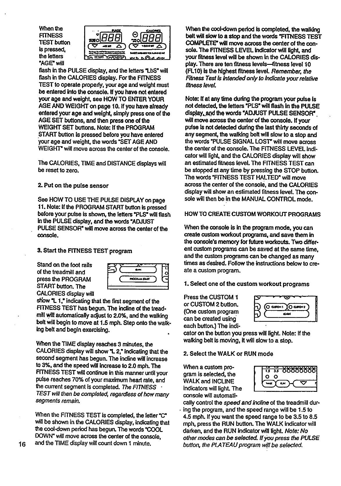
1. Select one of the custom workout programs
Press the CUSTOM 1I-_ -- _' --I1
or CUSTOM 2 button. _n
(One custom program
can be created using
each button.) The indi-
cator on the button you press will light. Note: If the
walking belt is moving, it will slow to astop.
2. Select the WALK or RUN mode
When acustom pro- I "" "_
gram is selected, the
WALK and INCLINE
indicatorswill light. The
console will automati-
cally control the speed and incline of the treadmill dur-
- ing the program, and the speed range will be 1.5 to
4.5 mph. If you want the speed range to be 3.5 to 8.5
mph, press the RUN button. The WALK indicator will
darken, and the RUN indicator will light. Note: No
other modes can be selected, ffyou press the PULSE
button, the PLATEAU program v_/I be se/ected.
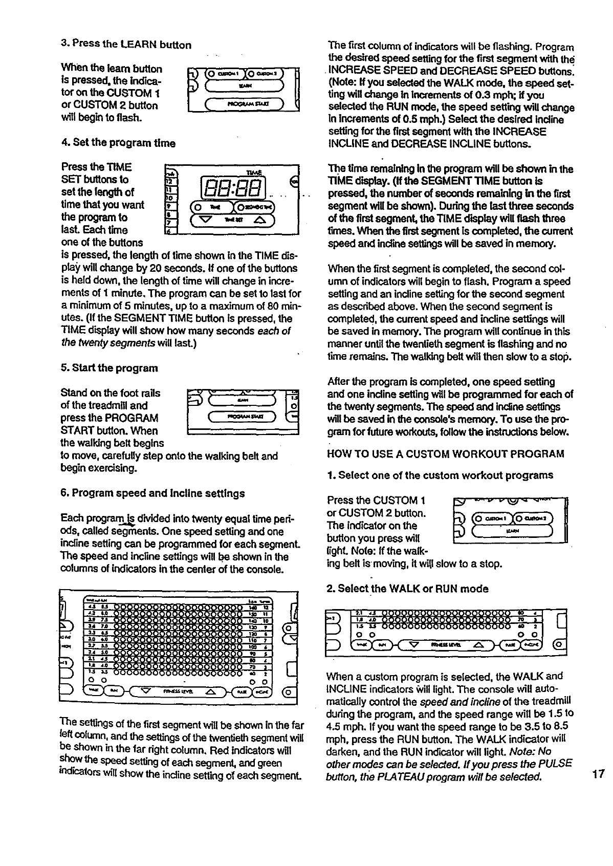
3. Press the LEARN button
When the Isam button
Is pressed, the Indica-
tor on the CUSTOM t
or CUSTOM 2 button
will begin to flash.
4. Set the program time
Press the TIME
SET buttons to
set the length of
time that you want
the program to
last. Each tlme
one of the buttons
., ° .
.,= A)
is pressed, the length of time shown in the TIME dis-
pla_'will change by 20 seconds. If one of the buttons
is held down, the length of time will change in incre-
ments of I minute, The program can be set Io last for
aminimum of 5 minutes, up to a maximum of 80 min-
utes. (If the SEGMENT TIME button Is pressed, the
TIME display will show how many seconds each of
the twenty segments will lasL)
5. Start the program
Stand on the foot rails _ (- :iI'_
of the treadmill and / ( "="='=' ) '-__
press the PROGRAM
START button. When /
the walking belt begins
to move, carefully step onto the walking belt and
begin exercising.
6. Program speed and Incline settings
Each program__ divided into twenty equal time peri-
ods, called segments. One speed setting and one
incline setting can be programmed for each segment.
The speed and incline settings will be shown in the
columns of indicators in the center of the Console.
The first Columrl of indicators will be flashing. Program
the desired speed setting for the first segment with the
•INCREASE SPEED and DECREASE SPEED buttons:
(Note: If you selected the WALK mode, the speed set-
ting will change In Increments of 0.3 mph; if you
selected the RUN mode, the speed setting will change
in increments of 0.5 mph.) Select the desired incline
setting for the first segment with the INCREASE
INCLINE and DECREASE INCLINE buttons.
The tlme remaining in the program will be shown in the
TIME display. (If the SEGMENT TIME button is
pressed, the number of seconds remaining in the first
segment will be shown}. Dudng the last three seconds
of the first segment, the TIME display will flash three
times. When the first segment is completed, the current
speed and incline settings will be saved in memory.
When the first segment is Completed, the second Col-
umn of indicators will begin to flash. Program a speed
setting and an incline setting for the second segment
as descdbed above. When the second segment is
completed, the current speed and incline settings will
be saved in memory. The program will Continue in this
manner untilthe twentieth segment is flashing and no
time remains. The walking belt will then slow to a stop.
After the program is completed, one speed setting
and one incline setting will be programmed for each of
the twenty segments. The speed and inclinesettings
will be saved in the console's memory. To use the pro-
gram for future workouts,follow the instructions below.
ROW TO USE A CUSTOM WORKOUT PROGRAM
1. Select one of the custom workout programs
Press the CUSTOM 1 1:_ ..... _J " "-" li
or CUSTOM 2 button. _,., ._, ,.,....... U
The indicator on the
button you press will
tight. Note: If the walk-
ing belt ismoving, it wi|l slow to astop.
2. Select the WALK or RUN mode
E
The settings of the firstsegment will be shown inthe far
leftcolumn, and the settings of the twentieth segmentwill
be shown in the far dght column, Red indicatorswill
showthe speed settingof each segment, and green
ind{cators will show the incline setting of each segmenL
pI=a =J O_O00000UO000000_)0000 Io • I
1:',;: ggggsgg%8888gggg888:II
When acustom program is selected, the WALK and
INCLINE indicators _vill light. The Console will auto-
meticaUy control the speed and incline of the treadmill
dudng the program, and the speed range will be 1.5 to
4.5 mph. If you want the speed range to be 3.5 to 8.5
mph, press the RUN button. The WALK indicator will
darken, and the RUN indicator will light. Note: No
other modes can be selected. If you press the PULSE
button, t/_ePLATEAU program will be selected. 17
3. The program settings
The speed and incrmesettings of the program you
have selected will be showninthe columns of ind'_a-
tom in the canter of the consdie.Red Indicators wiU
show the speed setting of each segment, and green
indicatorswill show the Inclinesetting of each segment.
• 4. Adjust the difficutty level of the program
ffdesired, the diffisultylevel of the program can be
adjusted with the RTNESS LEVEL buttons (see the
drawing above). Each time the FITNESS LEVEL
increase buttonis pressed,the speed and incline set-
tings of all segments will increase. Each time the FIT-
NESS LEVEL decrease buttonis pressed, the speed
and Inclinesettings of all segments will decrease.
Note: The dift"_ultylevel of the program can be
increased only untnthe highestindicator in one of the
columns is lit, and decreased only until the lowest indi-
cator inone of the columns is lit.
5, Adjust the program time
Step onto the walking belt and begin exercising.
The time remainingin the program will be shownin the
TIME display.(If the SEGMENT TIME buttonis pressed,
the numberof seconds remaining in the first segment
willbe shown).Dur_ the last three seconds ofthe first
segment,the TIME displaywill flash three times.When
the firstsegmentis completed, the second columnof
ind'_atorswill begin to flash, and the treadmillwill auto-
metisally adjustto the speed and inclinesettingsof the
secondsegment.The program wi_ continuein _ man-
net untilthe twentieth columnis flashing and notime
remains.The walking belt will then slow to a stop.
.....; oto- the the =thepro-
gramcan be adjusted with the FITNESS LEVEL but-
tons. The length of time that the program will last can
be changed with the TIME SET buttons. The program
can be stoppedat any time with the STOP button. The
consolewill then be in the same state as if the pro-
gram had been completed.
Note:Althoughthe difficulty level of the program can be
adjusted, only the original speed and incline settings
will be saved in memory. If you desire to change the
o_ginalspeed and |ndine settings, see HOW TO CRE-
ATE CUSTOM WORKOUT PROGRAMS onpage 16.
HOW TO TURN OFF THE POWER
To turn offthe power, remove the key fromthe con-
sole, Store the key in a secure location.
In addition, move the on/off switch to the "oft"position.
(See the drawing near the bottom of page 10.)
18
the program will
last can be adjust-
ed, if desired, with (o ,,_ Io==._,,_
the-TiME SET but- _ _, . _=, A )
tons. Each time
one of the buttons
is pressed, the length of time will cl_ange by 20 sec-
onds. If one of the buttonsis held down, the length of"
time wiii change in increments of 1 minute. The pro-
gram can be set to last fora minimum of 5 minutes, up
to a maximum of 80 minutes. (If the SEGMENT TIME
button is pressed, the TiME display will show how
many seconds each of the twenly segments will last.)
6. Start the program
Standonthe foot rails _ _- ,,_'_" _ _
of the treadmill and
press the PROGRAM ( "="=="_ )
START button.The first
column of indicatorswill
•begin to flash, and the treadmill will automatically adjust
to the speed and incline settions of the first s,_m_nt
HOW TO SELECT THE iNFORMATION MODE
The console features an information mode that keeps
track of trip time arid distance, as well as the total time
and d'_nca accumulated.
To select the information mode,hold down the STOP
•buttonwh_leinserting the key into the console.The .
indicatoron the SEGMENT TiME buttonwill light, and
the trip time and distanca witt be shown in the TiME
and DISTANCE displays. (Note: If the distance
exceeds 999 miles, the thousands digits will be shown
In the SPEED display.) If desired, the trip time and dis-
tance can be reset to zero by pressing the TIME SET
decrease button.
To view the total time and distance, press the TIME
button.The totaltime and distance will then be shown.
The tot_ time and distance cannot be reseL
Note: The PULSE display will
show the letter"I," indicating
that the console is set for an
infrared {n'_rdl_e,-_ nJd_:_ _n_nr
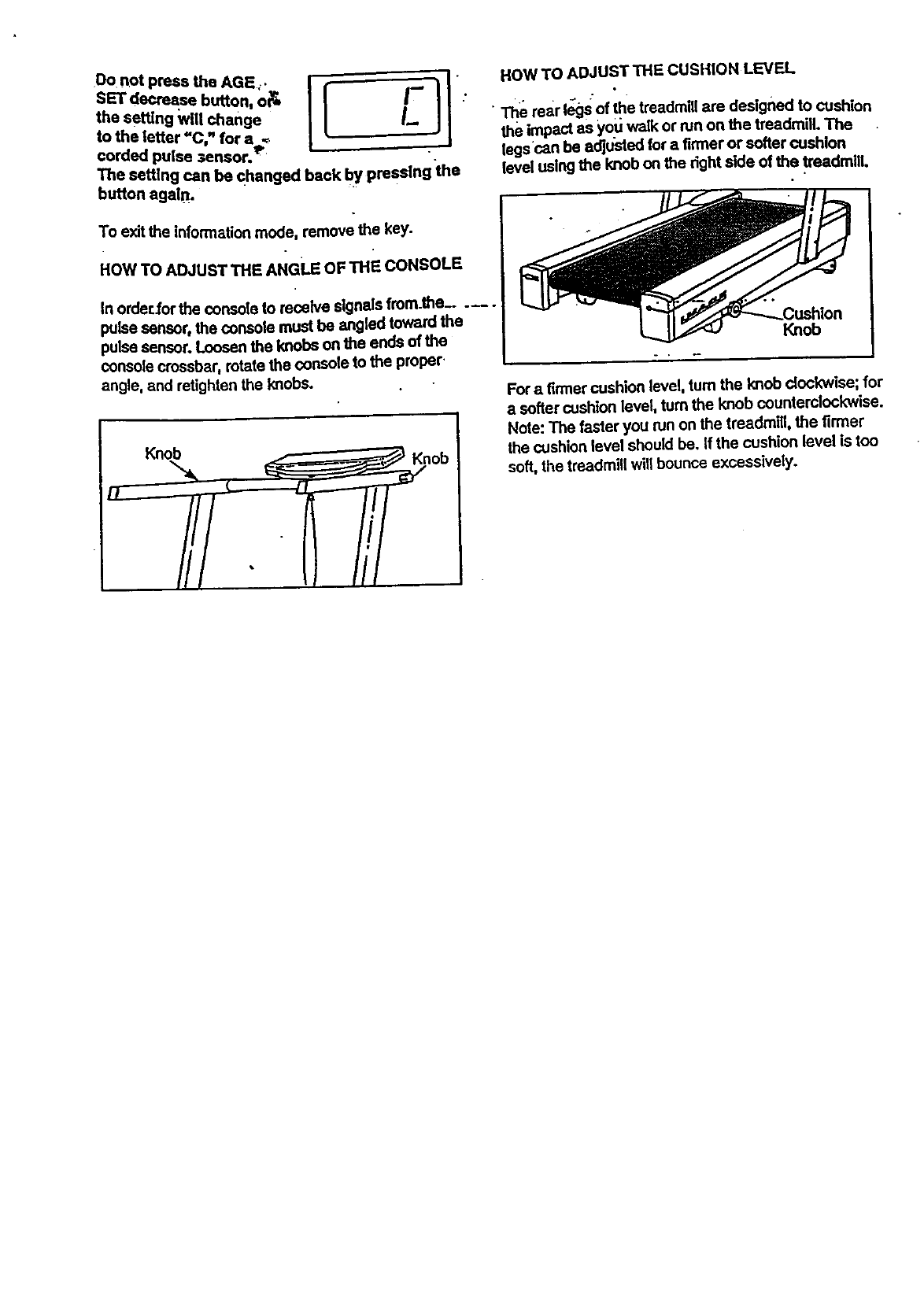
Do not press the AGE;.
SETdecreaseI_mo.,o&
to the letter "C," for aS
€orded pulse ;ensor. '
The setting can be changed back by pmaslng the
button agaln.
To exit the information mode, remove the key'.
HOWTOADJUSTTHeA"Gu orTHe-CONSOLe
In orderlor the console to receive signals from.the.....
pulse sensor, the console must be angled toward the
pulse sensor. Loosen the knobs on the ends of the
consolecrossbar, rotate the console to the proper.
angle, and retighten the knobs.
HOW TO ADJUST THE CUSHION LEVEL
•The rear legs of the treadmill are designed to cushion
the impact as you walk or run on the treadmill. The
legscan be e_us'ted for afirmer or softer cushion
level using the knob on the dght side of the treadmill.
Knob
For a firmer cushion level, turn the knob dock'wise; for
a softer cushion level, turn the knob counterclockwise.
Note: The faster you run on the treadmill, the firmer
the cushion level should be. If the cushion level is too
soft, the treadmill will bounce excessively.
TROUBLE-SHOOTING AND STORAGE
Most treadmill problems can be solved by following the simple steps below, Rnd the symptom that
=al_plles,'and follow the steps listed. If further assistance is needed, call our toll-free HELPLINE at 1-800-
736-6879, Monday through Saturday, 7 a.m. until 7 p.m. Central "rime (excluding holidays).
1. SYMPTOM: THE POWER DOES NOT TURN ON
•a. Make sure that the power cord Is pluggedinto a surge pmtedor, and that the surge protector is plugged into
apropedy grounded outleL (See HOW TO PLUG IN THE POWEI_ CORD on page 9.) Use only a UL-IIsted
surge protector, rated at 15 amps, witha 14-gauge cord of five feet or le_ in length.
b. After the power cord has been pluggedIn, make sure that the key Is fully Inseded into the console. Various
ind'zeatorson the console should light.(See HOW TO TURN ON THE POWER on page 10.)
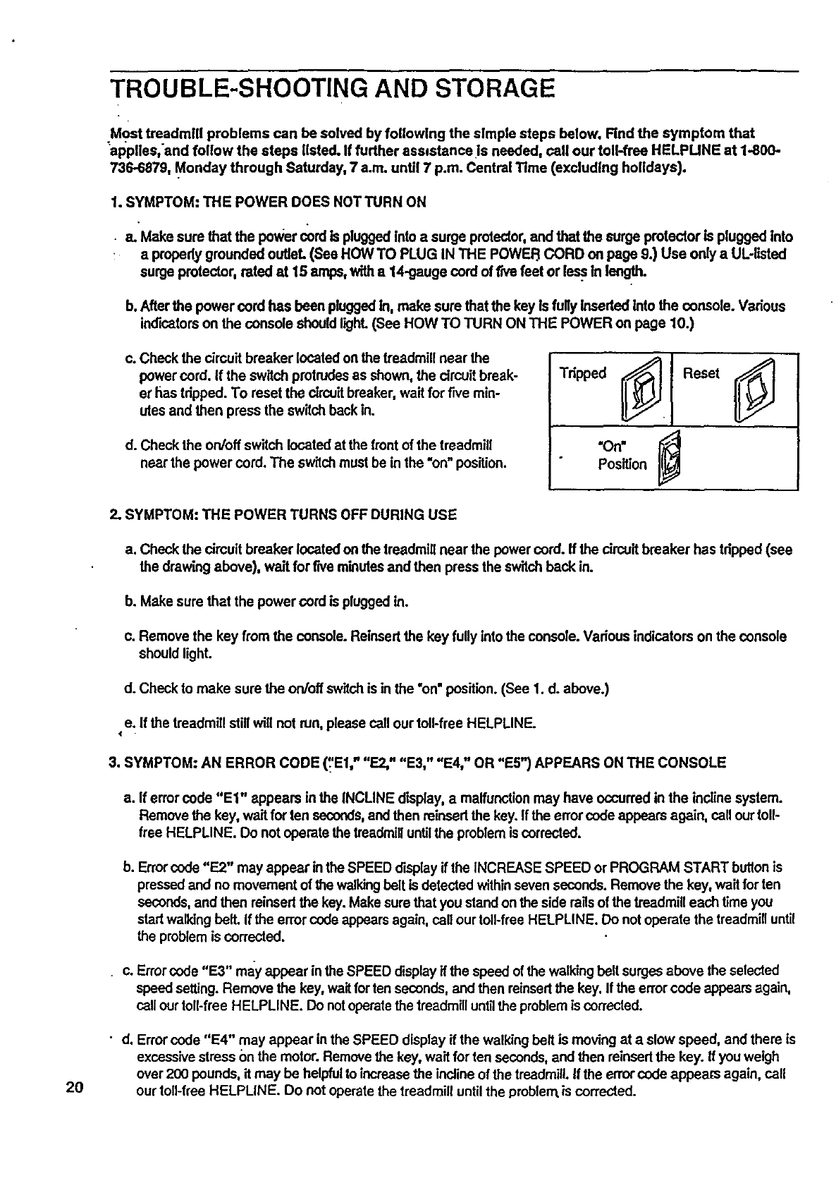
c. Check the circuit breaker located on the treadmill near the
power cord. If the switch protrudesas shown, the circuit break-
er has tdppod. To reset the circuitbreaker, wait for f'we min-
utes and then press the switchback in.
d. Check the on/off switch located at the front of the treadmill
near the power cord. The switchmust be in the "on"position.
Tripped _. Reset
"On=
Position
2. SYMPTOM: THE POWER TURNS OFF DURING USE
a. Check the cimuit breaker located on the treadmill near the power cord. If the circuitbreaker has tdpped (see
the drawing above), wait for rwe minutesand then press the switchback in.
b. Make sure that the power cord is plugged in.
c. Remove the key from the console. Reinsed the key fully Into the console. Various indicators on the console
should light.
d. Check to make sure the on/off switchis inthe "on"position. (See 1. d. above.)
e. If the treadmill still will not tun, please call our toll-free HELPLINE.
3. SYMPTOM: AN ERROR CODE (':'El," "E2," "E3," "E4," OR "ES") APPEARS ON THE CONSOLE
a. If error code "El" appears in the INCLINE display, a maffunotionmay have occurred in the incline system.
Remove the key, wa'_for ten seconds,and then reinsed the key. Ifthe error code appears again, call our toll-
tree HELPLINE. Do not operate the treadmilluntilthe problem IScorrected.
b. Errorcode "E2" may appear in the SPEED display if the INCREASE SPEED or PROGRAM START buttonis
pressed and no movement of the walkingbelt is detected withinseven seconds. Remove the key, wait for ten
seconds, and then reinsed the key. Make sure that you stand on the side railsof the treadmill each time you
start walkingbelt. If the error code appears again, call our toll-free HELPLINE. Do not operate the treadmilluntil
the problem is corrected.
c. Error code "E3" may appear inthe SPEED display ifthe speed of the walkingbelt surges above the selected
speed setting. Remove the key, waitfor ten seconds, and then reinsed the key. If the errorcode appears again,
call our toll-free HELPLINE. Do not operate the treadmill until the problem is corrected.
2O
d. Errorcode "E4" may appear in the SPEED display if the walking belt is moving at a slow speed, and there is
excessivestress on the motor. Remove the key, wait for ten seconds,and then reinsed the key. If you weigh
over 200 pounds, it may be helpful to increase the incline of the treadmill.If the error code appealS again, call
our toll-free HELPLINE. Do net operate the treadmill untilthe problem is corrected.
e. Errorcode "E5" may appear in the PULSE display if apulse error occurs. See HOW TO USE THE PULSE
SENSOR on pages 7 and 8, and HOW TO USE THE PULSE DISPLAY on page 11.
4. SYMPTOM: THE PULSE SENSOR DOES NOT FUNCTION PROPERLY
a. See HOW TO USE THE PULSE SENSOR on pages 7 and 8.
5. SYMPTOM: THE WALKING BELT SLOWS WHEN WALKED ON
a. Use only aUL-listed surge protector, rated at 15 amps, with a 14-gauge cord of f'wefeet or less in length.
b. If the walking belt still slows when walked on, please call our toll-free HELPUNE.
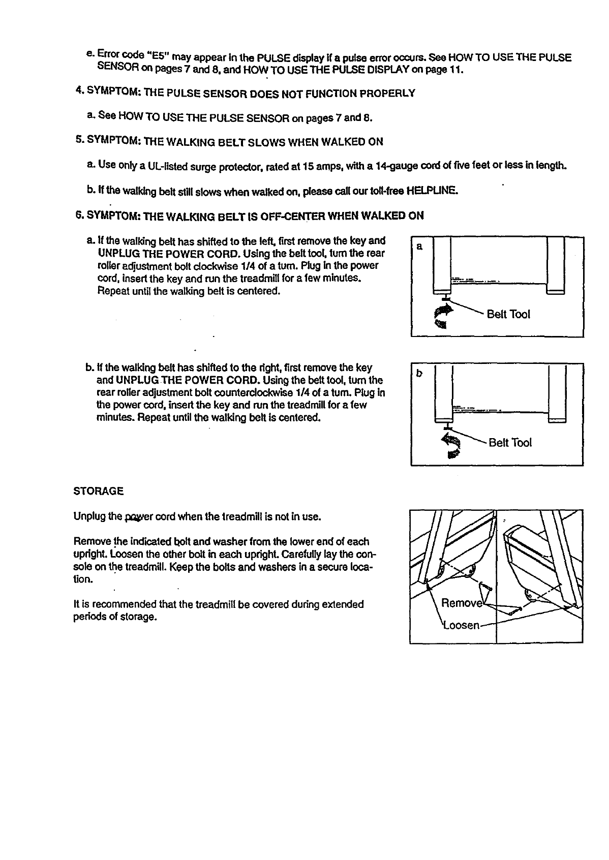
6. SYMPTOM: THE WALKING BELT IS OFF-CENTER WHEN WALKED ON
a. If the walking belt has shifted to the left, first remove the key and
UNPLUG THE POWER CORD. Using the belt tool, turn the rear
roller adjustment bolt clockwise 1/4 of a turn. Plug in the power
cord, insert the key and run the treadmill for afew minutes.
Repeat untilthe walking belt is centered.
q=
b. If the walking belt has shifted to the right, first remove the key
and UNPLUG THE POWER CORD. Using the belt tool, turn the
rear roller adjustment bolt counterclockwise 1/4 of a turn. Plug in
the power cord, insert the key and run the treadmill for afew
minutes. Repeat until the walking bolt is centered.
Belt Tool
STORAGE
Unplug the p_c_ercord when the treadmill is not in use.
Remove .theindicated I_oltand washer from the lower end of each
upright. Loosen the other bolt in each updghL CerefuUy lay the con-
sole on _e treadmill. Keep the bolts and washers in a secure loca-
tion.
It is recommended that the treadmill be covered during extended
periods of storage.
CONDITIONING GUIDELINES
22
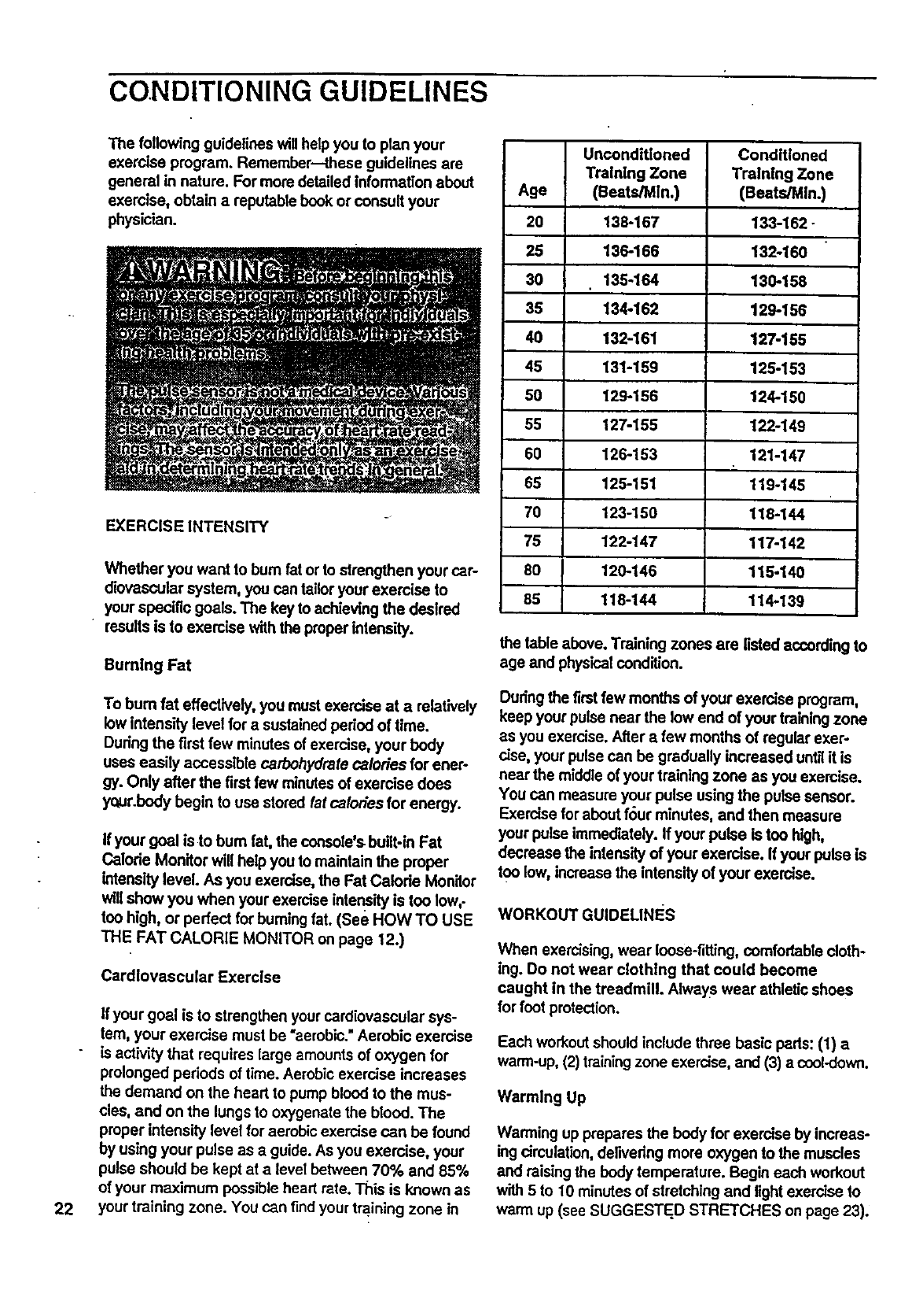
The following guidelines willhelp you to plan your
exercise program. Remember--these guidelines are
general in nature. For more detailed information about
exercise, obtain a reputable book or consult your
physician.
EXERCISE INTENSITY
Whether you want to bum fat or to strengthen your car-
diovascular system, you can tailor your exercise to
your specific goals. The key to achieving the desired
results is to exercise with the proper intensity.
Bumthg Fat
To bum fat effectively, you must exercise at a relatively
lowintensity level for asustainedperiod of time.
Duringthe first few minutes of exercise, your body
uses easily accessible carbohydrate calories for ener-
gy. Only after the firstfew minutes of exercise does
your.body begin to use stored fatcalories for energy.
If your goal is to bum fat, the console's built-in Fat
Calode Monitor will help you to maintain the proper
intensity level. As you exercise, the Fat Calode Monitor
will show you when your exercise intensity is toe low,-
too high, or perfect for burning fat. (see HOW TO USE
THE FAT CALORIE MONITOR on page 12.)
Cardiovascular Exerclse
If your goal is to strengthen your cardiovascular sys-
tem, your exercise must be "aerobic."Aerobic exercise
is activity that requires large amounts of oxygen for
prolonged pedods of time. Aerobic exercise increases
the demand on the heart to pump blood to the mus-
cles, and on the lungs to oxygenate the blood. The
proper intensity level for aerobic exercise can be found
by using your pulse as a guide. As you exercise, your
pulse should be kept at alevel behveen 70% and 85%
of your maximum possible heart rate. "l"his is known as
your training zone. You can find your training zone in
Unconditioned
Training Zone
Age (Beats/Mln.)
20 138-167
25 136-166
30 135-164
35 134-162
40 132-161
45 131-159
50 129-156
55 127-155
60 126-153
65 125-151
70 123-150
75 122-147
80 120-146
85 118-144
Conditioned
Training Zone
(Beats/MIn.)
133-162-
132-160
130-158
129-166
127-165
125-153
124-150
122-149
121-147
119-145
118-144
117-142
116-140
114-139
the table above. Training zones are listed according to
age and physicalcondition.
Dudng the first few months of your exercise program,
keep your pulse near the low end of your trainingzone
as you exercise. After a few months of regular exer-
cise, your pulse can be gradually increased until it is
near the middle of your training zone as you exercise.
You can measure your pulse using the pulse sensor.
Exercise for about four minutes, and then measure
your pulse immediately. If your pulse is toe high,
decrease the intensityof your exercise. If your pulse is
toe low, increase the intensity of your exercise.
WORKOUT GUIDELINES
When exercising, wear loose-fitting, comfortable cloth-
ing. Do not wear clothing that could become
caught in the treadmill. Always wear athletic shoes
for foot protection.
Each workoutshould include three basic pads: (1) a
warm-up, (2) trainingzone exercise, and (3) a coct-down.
Warming Up
Warming up prepares the body for exercise by increas-
ing circulation,deilvedng more oxygen to the muscles
and raising the body temperature. Begin each workout
with 5 to 10 minutes of stretching and lightexercise to
warm up(see SUGGESTED STRETCHES on page 23).
TralntngZoneExercise
Afterwarmingup,increase the intensity of your exer-
cise untilyour pulse is in your training zone for 20 to
60 minutes, (During the firstfew weeks of your exer-
cise program, do not keep your pulse in your training
zone for longer than 20 minutes.) Breathe regularly
and deeply as you exercise--never hol.dyour breath,
Cooling Down
Rnish each workout with S to 10 mlnutes of stretching
to cool down. This will inca'easethe flexibility of your
musclesand will help to prevent post-exerclse problems._
Exercise Frequency
To maintain or improve your condition, complete throe
workouts each week, with at least one day of rest
between workouts. After afew months, you may com-
plete up to five workouts each week if desired.
The key to success is to make exercise aregular and
enjoyable part of your everyday life.
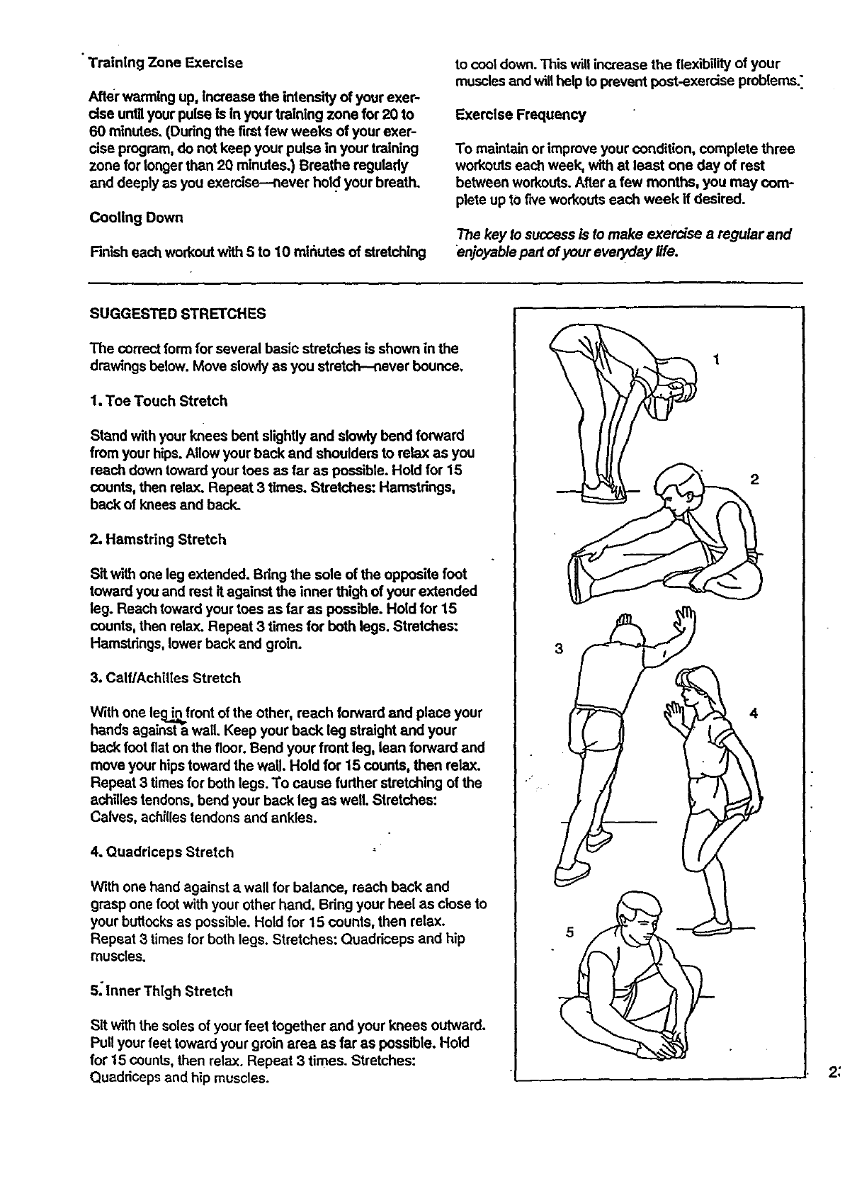
SUGGESTED STRETCHES
The correct form for several basic stretches is shown in the
drawings below. Move slowly as you stretch -nsver bounce.
1. Toe Touch Stretch
Stand withyour knees bent slightly and slowly bend forward
from your hips. Allowyour back and shoulders to relax as you
reach down toward your toes as far as possible. Hold for 15
counts, then relax. Repeat 3 times. Stretches: Hamstrings,
back of knees and back.
2. Hamstring Stretch
Sit with one leg extended. Bring the sole of the opposite foot
toward you and rest it against the inner thigh of your extended
leg. Reach toward your toes as far as possible. Hold for 15
counts, then relax. Repeat 3 times for both legs. Stretches:
Hamstrings, lower back and groin.
3. Calf/Achilles Stretch
With one leig__front of the other, reach forward and place your
hands against a wall. Keep your back leg straight and your
back foot fiat on the floor. Bend your front leg, lean forward and
move your hips toward the waU. Hold for 15 counts, then relax.
Repeat 3 times for both legs. To cause further stretching of the
achilles tendons, bend your back leg as well. Stretches:
Calves, achilles tendons and ankles.
4. Quadriceps Stretch
With one hand against awall for balance, reach back and
grasp one footwith your other hand. Bdng your heel as close to
your buttocksas possible. Hold for 15 counts, then relax.
Repeat 3 times for both legs. Stretches: Quaddceps and hip
muscles.
S; Inner Thigh Stretch
Sit with the soles of your feet together and your knees outward.
Pull your feet toward your groin area as far as possible. Hold
for 15 counts, then relax. Repeat 3 times. Stretches:
Quaddceps and hip muscles.
4
5
2:
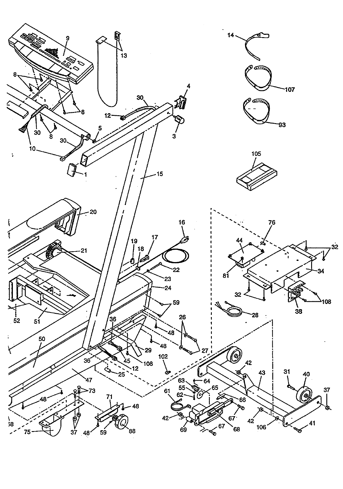
REMOVE THIS EXPLODED DRAWING
AND PART LIST FROM THE MANUAL
save this EXPLODED DRAWING and PART LIST for future reference.
Note: Specifications are subject to change without notice, For information about
ordering replacement parts, see the back cover of the user's manual.
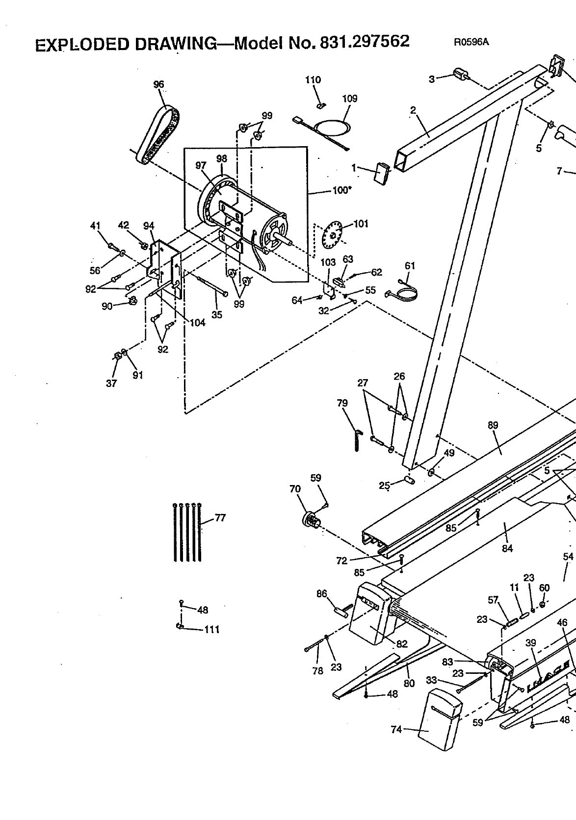
EXPLODED DRAWING--Model No. 831.297562 R059_A
96 11o
2
5
41 42 94
63 61
i
1
37
99
35
64........_
32 j°
jo
j-
jo
j°
79
\
26
27
89
59
78 23
.82
80
84 54
23 /
11 6O
46
39
9
5
13
3
_107
52 51
50
71
17
19
59
16
26
81
31 40
37
8,, .." 42 _/. 41
37 48 59 69 106
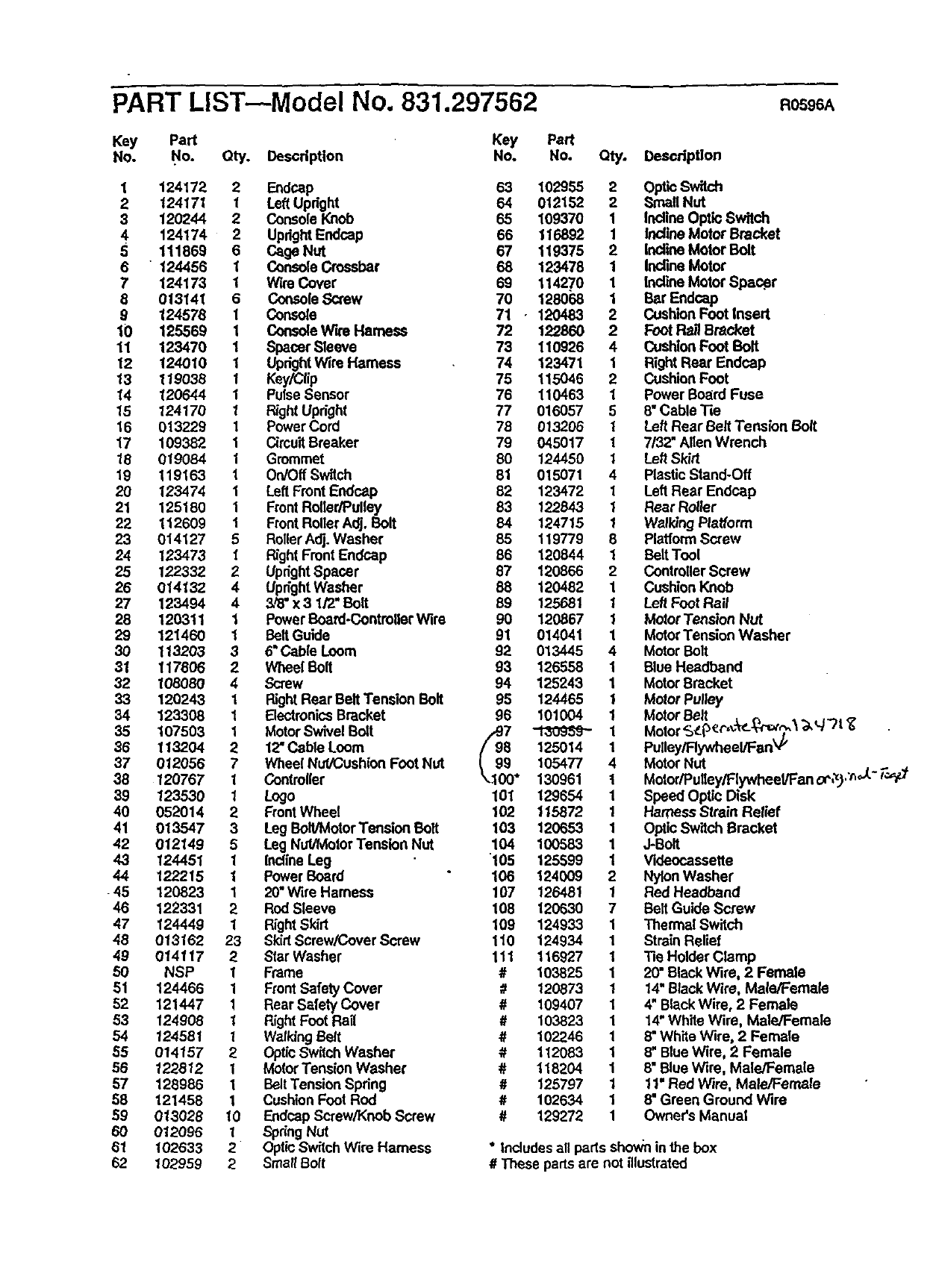
PART LIST--Model No. 831.297562 Ros A
Key Part Key Part
No. No. Qty. Description No, No. Qty. Description
1 124172 2 Endcap 63 102955 2
2124171 1 Left Updght 64 012152 2
3 120244 2 Console Knob 65 109370 1
4 124174 2 UprightEndcep 66 116892 1
5 111869 6 Cage Nut 67 119375 2
6 " 124456 1 Console Crossbar 68 123478 1
7 124173 1 Wire Cover 69 114270 1
8 013141 6 Console Screw 70 128068 1
9 124578 1 Console 71 .12048,3 2
10 125569 1 ConsoleW'n Harness 72 122860 2
11 123470 1 Spacer Sleeve 73 110926 4
12 124010 I UprightWire Harness 74 123471 1
13 119038 1 Key/Cflp 75 115046 2
14 120644 I PulseSensor 76 110463 1
15 124170 1 RightUpright 77 016057 5
16 013229 1Power Cord 78 013206 1
17 109382 1 Circu'dBreaker 79 045017 1
18 019084 1Grommet 80 124450 1
19 119163 1 On/OffSwitch 81 015071 4
20 123474 1 Left FrontEedcap 82 123472 1
21 125180 1 FrontRoller/Pulley 83 122843 1
22 112609 1 FrontRoller Adj. Bolt 84 124715 1
23 014127 5 RollerAdj. Washer 85 119779 8
24 123473 I Right FrontEndcap 86 120844 1
25 122332 2 UprightSpacer 87 120866 2
26 014132 4 UprightWasher 88 120482 1
27 123494 4 &_" x 3 1/2" Bolt 89 125681 1
28 120311 1 PowerBoard-ControllerWire 90 120867 1
29 121460 1 BeltGuide 91 014041 1
30 113203 36"Cable Loom 92 013445 4
31 117806 2Wheel Bolt 93 126558 1
32 108080 4 Screw 94 125243 1
33 120243 1 Right Rear Belt Tendon Bolt 95 124465 1
34 123308 1 ElectronicsBracket 96 101004 1
35 107503 1 MotorSwivel Bolt /97 _1
36 113204 2 12"Cable Loom /(98 125014 1
37 012056 7 Wheel NuVCushicn Foot Nut I99 105477 4
38 120767 1 Controller k..100° 130961 t
39 123530 1Logo 101 129654 1
40 052014 2 FrontWheel 102 115872 1
41 013547 3 Leg Bolt/Motor Tension Bolt 103 120653 1
42 012149 5 Leg Nut/Motor Tension Nut 104 100683 1
43 124451 1 inclineLeg 105 125599 1
44 122215 I PowerBoard 106 124009 2
45 120323 1 20"Wire Harness 107 126481 1
46 122331 2 Rod Sleeve 108 120630 7
47 124449 1 RightSkirt 109 124933 1
48 013162 23 SkidScrew/Cover Screw 110 124934 1
49 0141 t 7 2 Star Washer 111 116927 1
50 NSP 1 Frame #103825 1
51 124466 1 FrontSafety Cover #120873 1
52 121447 1 Rear Safety Cover #109407 1
53 124908 1 Right Foot Rail #103823 1
54 124581 1 Walking Belt # 102246 1
55 014157 2 OpticSwitch Washer #112083 1
56 122812 I MotorTension Washer # 118204 1
67 128986 1 Belt Tension Spring #125797 1
88 121458 1 CushionFoot Rod #102634 1
59 013028 10 Eodcap Screw/Knob Screw #129272 1
6O 012O96 1SpringNut
61 102633 2 Optic Switch Wire Harness ° Includesall paris shown in the box
62 102959 2Small8ott #These partsare not illustrated
OpticSwitch
Small NUt
Incline Optio Switch
InclineMotor Bracket
Incline Motor Bolt
InclineMotor
Incline Motor Spac#r
Bar Endcep
CushionFoot Insert
Foot R_ Bracket
CushionFoot Bolt
RightRear Endeap
CushionFoot
Power Board Fuse
8" Cable Tie
Left Rear Belt Tension Bolt
7/32" Allen Wrench
Left Skirt
PlasticStand-Off
Left Rear Endoap
Rear Roller
Walking Platform
PlatformScrew
BeltTool
ControllerScrew
CushionKnob
Left Foot Rail
MotorTension Nut
MotorTension Washer
MotorBolt
Blue Headband
MotorBracket
Motor Pulley
MotorBolt
Motor %__p_(-,,:_..-_rot?,__,q"Tt <_
Pulley/Rywheel/Fan'_"
Motor Nut
Motor/Pulley/Flywheel/Fan oP,_),'nJ-" r',_
Speed Optic Disk
Harness Strain Relief
Optic Switch Bracket
J-Bolt
Videocassette
NylonWasher
Red Headband
Belt Guide Screw
Thermal Switch
Strain Relief
Tie Holder Clamp
20" Black Wire, 2 Female
14"Black Wire, Male/Female
4" BlackWire, 2 Female
14"White Wire, Male/Female
8" White Wire, 2 Female
8" Blue Wire, 2 Female
8" Blue Wire, Male/Female
11" Red Wire, MaleJFemale
8" Green Ground Wire
Owner's Manual
o. ,
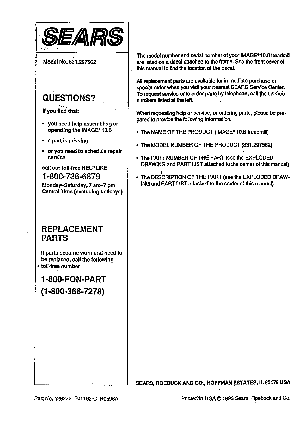
Model No. 831.297562
QUESTIONS?
If you find"that:
•you need help assembling or
operating the IMAGE" 10.6
• a part is missing
•or you need to schedule repair
service
call our toll-free HELPUNE
1-800-736-6879
Monday-Saturday, 7 am-7 pm
Central Time (excluding holidays)
REPLACEMENT
PARTS
If parts become worn and need to
be replaced, call the following
toll-free number
1-800-FON-PART
(1-800-366-7278)
The model number and serial number of your IMAGE'10.6 treadmill
are listed on a decal attached to the frame. See the front cover of
this manual to find the location of the decal.
Allreplacementpadsare available for Immediatepurchaseor
specialorderwhenyouvisityournearestSEARS ServiceCenter.
To requestserviceor to orderpads bytelephone,call.thetoll-flee
numberslistedat the left,
When requesting help or service, or ordedng parts, please be pre-
pared to provide the following information:
• The NAME OF THE PRODUCT (IMAGE +10.6 treadmill)
• The MODEL NUMBER OF THE PRODUCT (831.297562)
•The PART NUMBER OF THE PART (see the EXPLODED
DRAWING and PART LIST attached to the center of this manual)
•The DESCRIPTION OF THE PART (see the EXPLODED DRAW-
ING and PART UST attached to the canter of this manual)
SEARS, ROEBUCK AND CO., HOFFMAN ESTATES, IL 60179 USA
Part No. 129272 F01162-C R0596A Pdnted_in USA ©1996 Sears, R.oebuckand Co.
