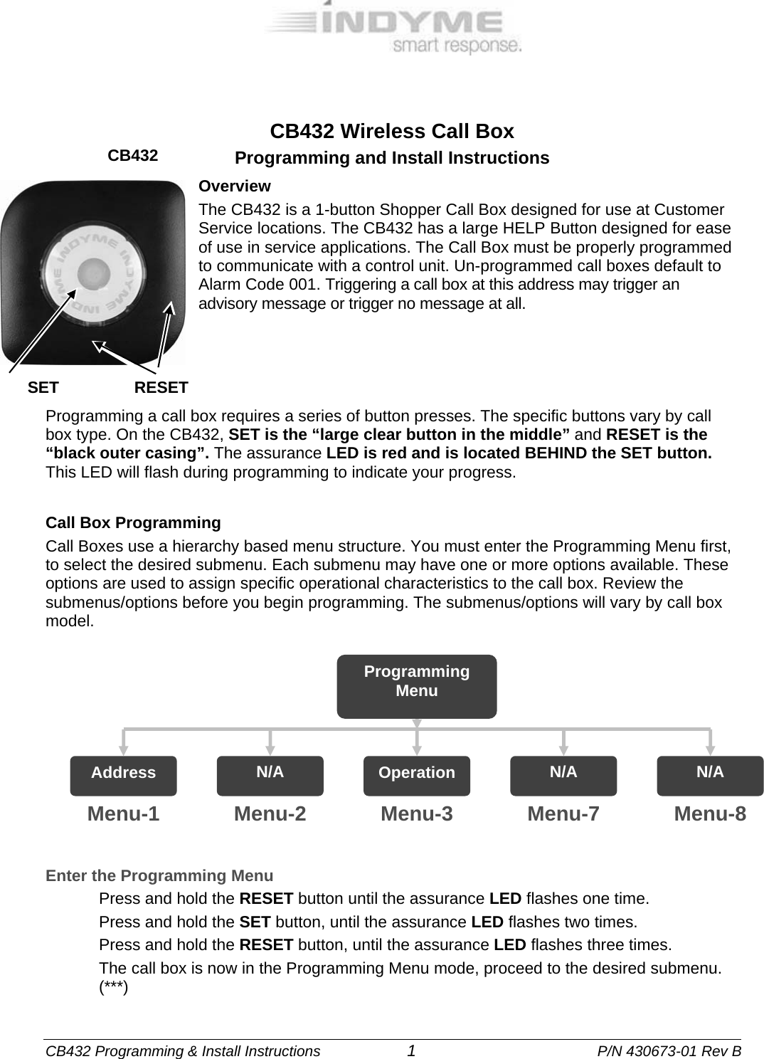
Indyme Solutions CB432 Call Button User Manual 430673 01 RevB CB432

Indyme Solutions, Inc Call Button 430673 01 RevB CB432

User Manual

 CB432 Programming & Install Instructions                     1                                        P/N 430673-01 Rev B  CB432 Wireless Call Box Programming and Install Instructions Overview The CB432 is a 1-button Shopper Call Box designed for use at Customer Service locations. The CB432 has a large HELP Button designed for ease of use in service applications. The Call Box must be properly programmed to communicate with a control unit. Un-programmed call boxes default to Alarm Code 001. Triggering a call box at this address may trigger an advisory message or trigger no message at all.      Programming a call box requires a series of button presses. The specific buttons vary by call box type. On the CB432, SET is the “large clear button in the middle” and RESET is the “black outer casing”. The assurance LED is red and is located BEHIND the SET button. This LED will flash during programming to indicate your progress.  Call Box Programming Call Boxes use a hierarchy based menu structure. You must enter the Programming Menu first, to select the desired submenu. Each submenu may have one or more options available. These options are used to assign specific operational characteristics to the call box. Review the submenus/options before you begin programming. The submenus/options will vary by call box model.           Enter the Programming Menu Press and hold the RESET button until the assurance LED flashes one time. Press and hold the SET button, until the assurance LED flashes two times. Press and hold the RESET button, until the assurance LED flashes three times. The call box is now in the Programming Menu mode, proceed to the desired submenu. (***)  Programming Menu Address  N/A  Operation  N/A  N/A Menu-1  Menu-2  Menu-3  Menu-7  Menu-8 CB432 RESET SET
 CB432 Programming & Install Instructions                     2                                        P/N 430673-01 Rev B   Menu-1: Call Box Address Programming  Assigns the call box to a corresponding alarm event programmed in the control unit. A call box address is a three digit number from 001 to 999. Leading zeros are required.  After entering the Programming Menu; Press the SET button one time for Menu-1, RESET once to save. The assurance LED will flash one time to indicate Menu-1 was selected. Use SET and RESET to program the 3-digit address as follows; SET = digits 1-9, RESET = digit 0 and SAVE. Leading zeros are required  For example, program Alarm-082 as follows:  Press RESET once to represent the zero. (0)  Press SET eight times, RESET once to save. (8)  Press SET two times, RESET once to save. (2) Note: When the RESET button is pressed to save the 3rd digit, the assurance LED will flash to indicate the address that was entered. The assurance LED will indicate digit zero by a long flash. (approximately 1-sec.)   Menu-3: Call Box Operating Mode Assigns the call box operating characteristics; timeout duration, RESET signal and number of active buttons. Operating Modes will vary by call box type, below are the default modes for this call box. After entering the Programming Menu; Press the SET button three times for Menu-3, RESET once to save. The assurance LED will flash three times to indicate Menu-3 was selected. Press the SET button to select a Call Box Operating Mode: <1, 2, >, RESET once to save. The assurance LED will flash to indicate the selected Operating Mode.   Mode 1 - 1-Button Call Box 5-min timeout, No Reset  Press the SET button to trigger the alarm state; the LED will flash for 5 minutes, then extinguish with no reset sent. The RESET button will send a reset signal for the active channel.    Mode 2 - 1-Button Call Box 30-sec timeout, No Reset   Same as above, with 30-second timeout.
 CB432 Programming & Install Instructions                     3                                        P/N 430673-01 Rev B  INSTALLATION AND TROUBLESHOOTING TIPS  1.  Identify all programming characteristics before you begin programming or installation.   Call Box Addresses    Call Box Mode  Mounting Location 2.  Program the Alarm Address and Mode of each call box. 3.  Install the call box in accordance with store policy, Indyme work order and/or Americans with Disabilities Act guidelines where applicable. The CB432 Call Box uses two AA-size 1.5-volt alkaline batteries. Always use the same type of battery for optimum performance. To replace the batteries, remove the call box from its mounting location. Turn the call box over to the back of the call box. Remove the old batteries from the battery holders. Install the new alkaline batteries. (**) The call box does not loose the programmed characteristics when the batteries are removed.   Location Considerations Call boxes are typically located at cash registers, service counters or other areas in which customers require assistance. Stores and installers should be aware of the Americans with Disabilities Act (ADA) requirements for accessibility. Call Boxes use a low powered transmitter, and operate best with a clear line of sight to the nearest receiver. Tall shelving, merchandise and metal signs can block or reduce the call box signal. Install the Call Box 1.  Verify call box placement with the Store Manager and according to provided instructions. Determine the best mounting method before installing the call box, verify address programming.   Wall Mount    Counter Top Mount  Store Shelving  2.  The CB432 has 2-different mounting options available; wall or counter top. Choose the appropriate option for your situation. The CB432 mounting bracket MUST be used for wall or counter top installation.   Wall Mounting  1.  Identify the desired mounting height for the SET button.  2.  Align the mounting bracket at that the correct height so the words on the CB432 Button will be upright. 3.  If mounting to glass or a smooth non-porous surface, use the double-sided adhesive ONLY. If mounting to a solid surface or drywall, mark and drill through the two mounting holes.  4.  Insert mounting hardware in the two holes and secure the mounting bracket. a.  wall anchors and screws if drywall or masonry b.  screws only for wood.
 CB432 Programming & Install Instructions                     4                                        P/N 430673-01 Rev B    5.  Place the mounting holes on the back of the call box over the mounting tabs on the wall bracket; push the call box over the mounting tabs to snap in place. 6.  From the final mounting location, press the SET button on the call box and verify the appropriate message is broadcast over the desired output device.             NOTES:   (**)DO NOT use rechargeable batteries in the call box.  (***)The call box will automatically exit any programming menu if no buttons are pressed for 30-seconds.   FCC and Industry Canada Notice of Compliance This device complies with Part 15 of the FCC Rules. Operation is subject to the following two conditions:  (1) this device may not cause harmful interference, and (2) this device must accept any interference received, including interference that may cause undesired operation.    This device complies with Industry Canada licence-exempt RSS standard(s). Le carolcrum;présent appareil est conforme aux CNR d'Industrie Canada applicables aux appareils radio exempts de licence. L'exploitation est autorisée aux deux conditions suivantes : (1) l'appareil ne doit pas produire de brouillage, et (2) l'utilisateur de l'appareil doit accepter tout brouillage radioélectrique subi, même si le brouillage est susceptible d'en compromettre le fonctionnement.   Class B statement: This equipment has been tested and found to comply with the limits for a Class B digital device, pursuant to part 15 of the FCC Rules. These limits are designed to provide reasonable protection against harmful interference in a residential installation. This equipment generates, uses and can radiate radio frequency energy and, if not installed and used in accordance with the instructions, may cause harmful interference to radio communications. However, there is no guarantee that interference will not occur in a particular installation. If this equipment does cause harmful interference to radio or television reception, which can be determined by turning the equipment off and on, the user is encouraged to try to correct the interference by one or more of the following measures: •  Reorient or relocate the receiving antenna. •  Increase the separation between the equipment and receiver. •  Connect the equipment into an outlet on a circuit different from that to which the receiver is connected. •  Consult the dealer or an experienced radio/TV technician for help.   Any changes or modifications not expressly approved by the party responsible for compliance could void the user’s authority to operate the equipment. Mounting Bracket   Battery Compartment Mounting Tabs

Navigation menu