Indyme Solutions CB550 Wireless Director Call Box User Manual PT4 CU4400 INSTALL
Indyme Solutions, Inc Wireless Director Call Box PT4 CU4400 INSTALL
UserManual.wiki
>
Indyme Solutions
>
CB550 User Manual
>
Manual
Contents
1.
Manual
2.
manual inser
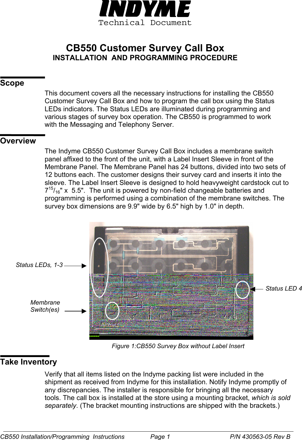
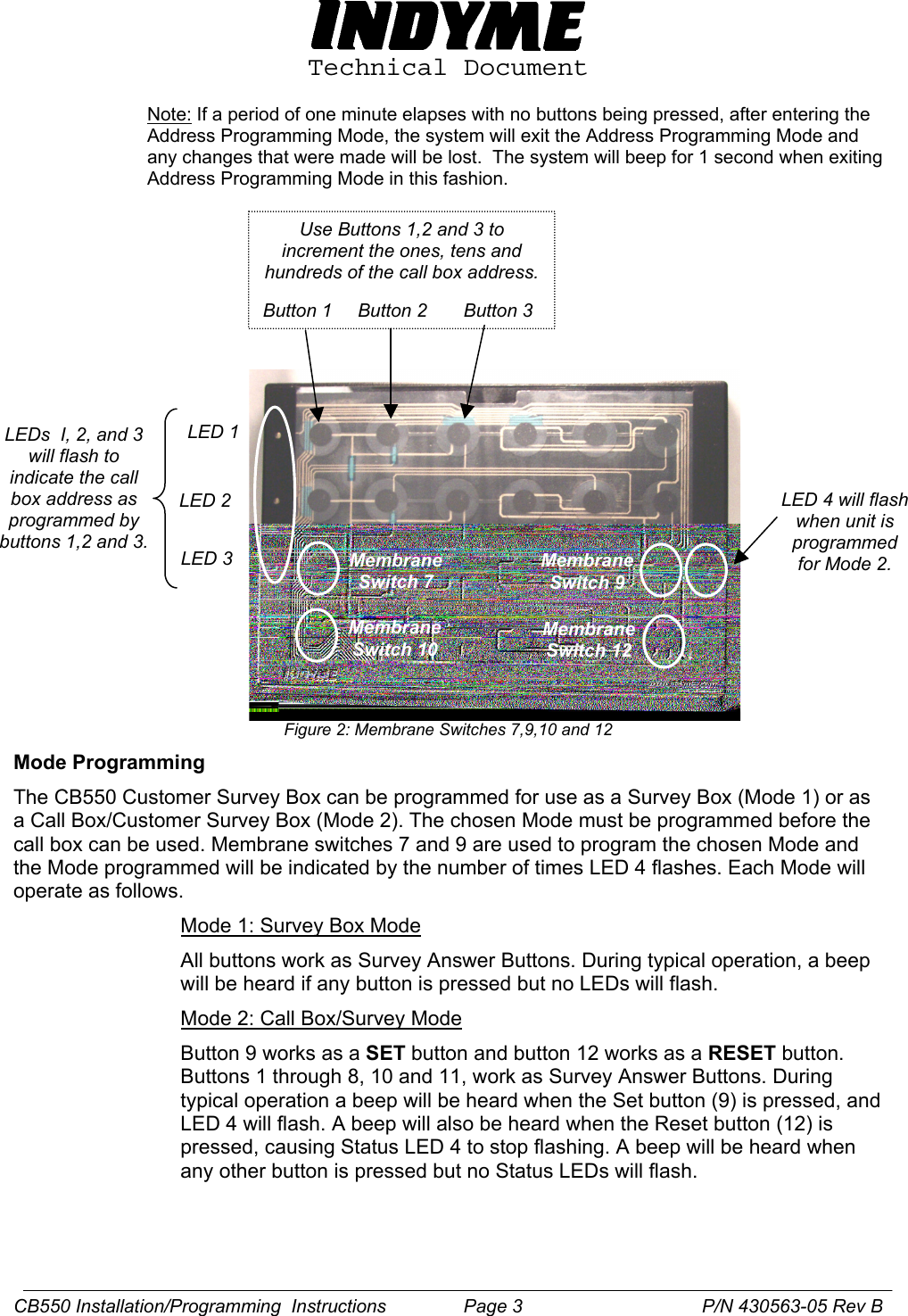
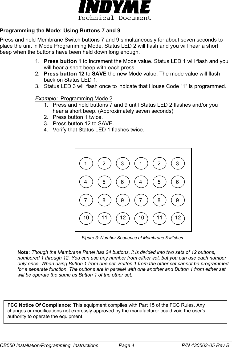
Manual
Navigation menu
Upload a User Manual
Namespaces
Wiki Guide
HTML
PDF
Info
Views
User Manual
Discussion / Help
Navigation