Indyme Solutions CB932 Wireless help button User Manual
Indyme Solutions, Inc Wireless help button
UserManual.wiki
>
Indyme Solutions
>
CB932 User Manual
User Manual
Navigation menu
Upload a User Manual
Namespaces
Wiki Guide
HTML
PDF
Info
Views
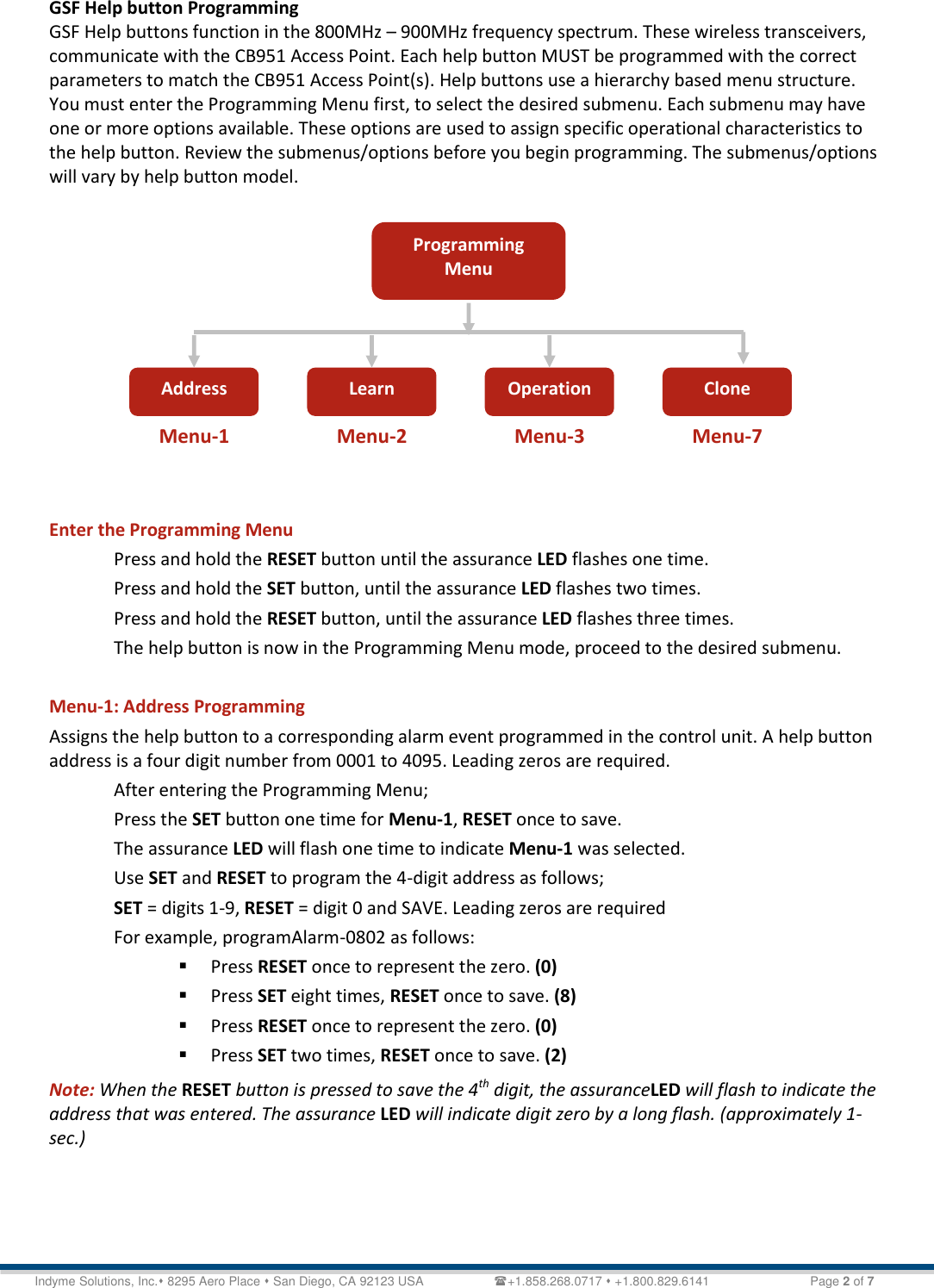
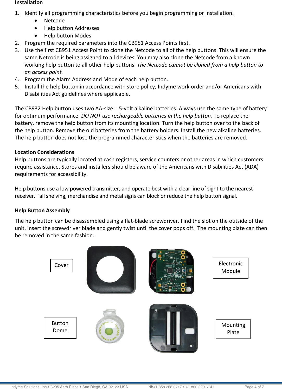
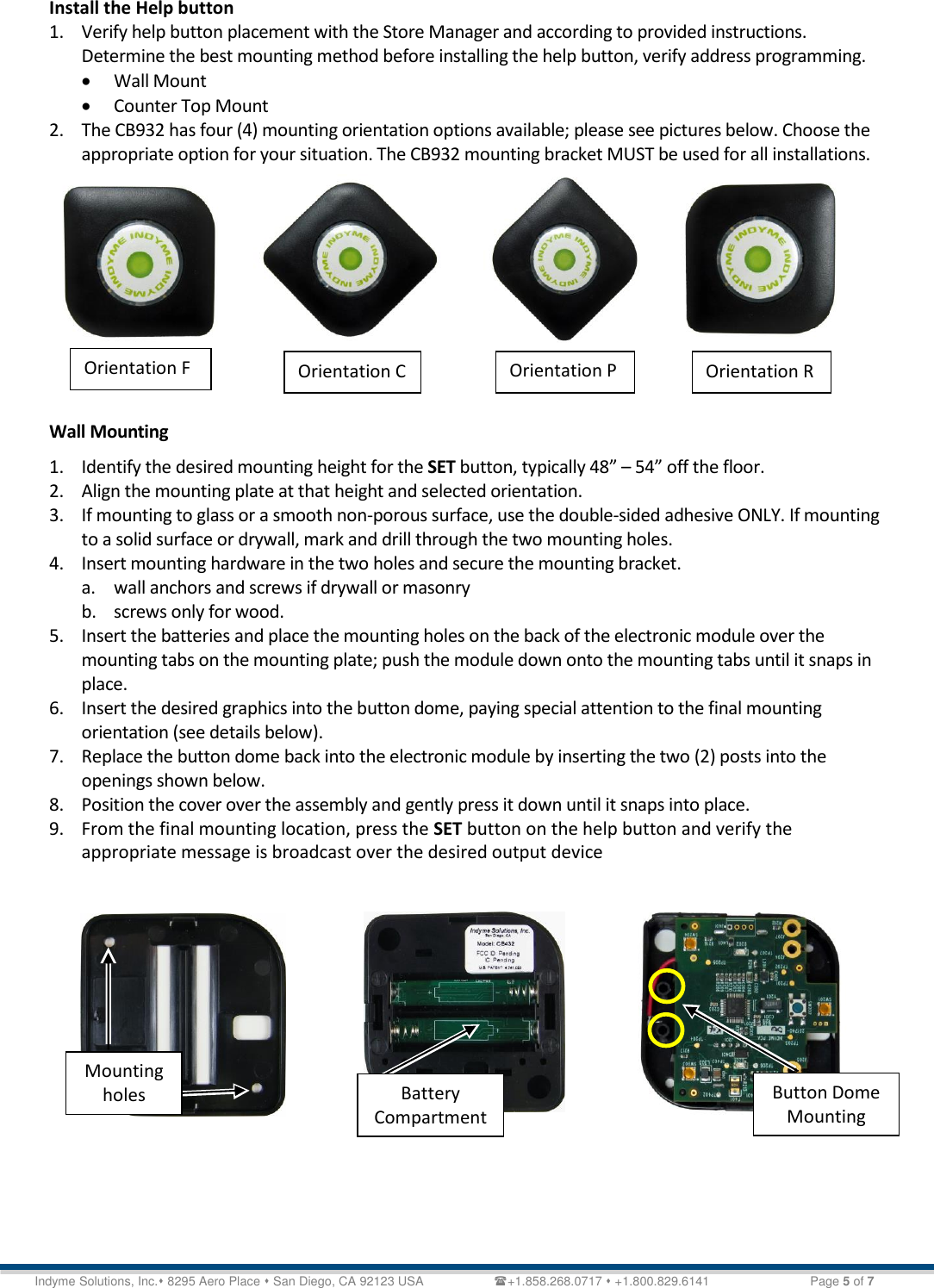
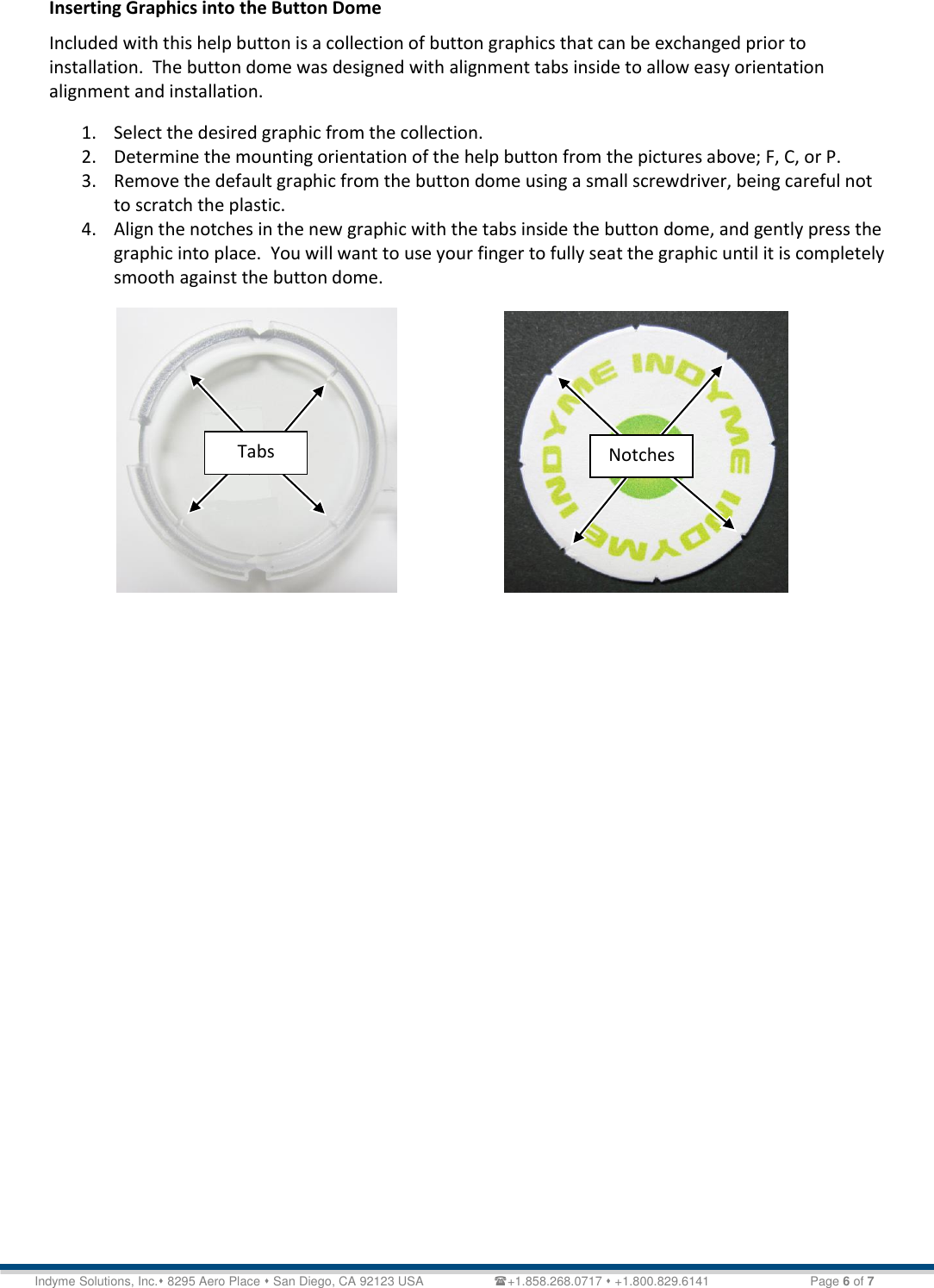
User Manual
Discussion / Help
Navigation