Indyme Solutions CB932 Wireless help button User Manual
Indyme Solutions, Inc Wireless help button
User Manual
Technical Document
430673-02
Rev. G
Indyme Solutions, Inc. 8295 Aero Place San Diego, CA 92123 USA +1.858.268.0717 +1.800.829.6141 Page 1 of 7
CB932 Wireless Help Button
Programming and Installation Instructions
Introduction
The CB932 is a member of the Global Solutions Family. Indyme GSF
products operate in the 800MHz – 900MHz frequency spectrum. The
CB932 is a 1-button, GSF help button designed for use at customer
service or sales floor locations. GSF Help Buttons are designed to
communicate with a GSF Access Point. GSF products are not
compatible with legacy devices.
Hardware
(2) #6 x 3/4” Phillips screw
(2) #6 plastic wall anchor
(2) strips, double sided adhesive
(1) package alcohol swap
(2) AA alkaline battery
Programming Parameters
GSF products MUST be properly programmed to establish communication. Programming parameters MUST
match your configuration. The default settings are for testing purposes only and should not be used. Failure
to properly program your help button and access point will prevent your devices from working.
GSF Help buttons have three primary programming parameters; Netcode, Address and Operating Mode.
These MUST be programmed in the correct order to establish communication and ensure proper operation.
Identify the parameters for your configuration before you begin programming.
Using the programming instructions below set the following parameters in order.
Netcode – unique identification code for the installation environment.
Address – alarm number associated with a control unit alarm event.
Operating Mode – defines how the help button will respond when activated.
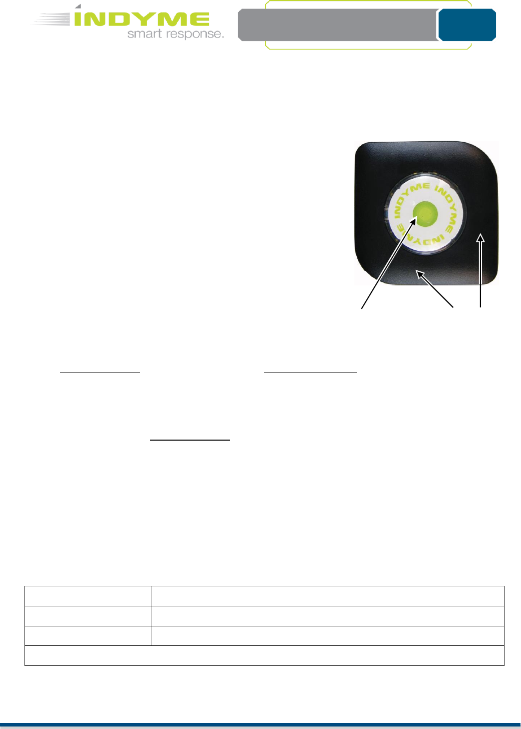
Programming a help button requires a series of button presses. The specific buttons vary by device type.
On the CB932, SET is the “large button in the middle” and RESET is “the black outer cover”. The
assurance LED is red and is located BEHIND to the SET button. This LED will flash during programming
to indicate your progress.
Netcode
*00000001
Address
*0001
Operating Mode
*1
* Default parameters are for testing purposes only.
CB932
RESET
SET
Technical Document
<Tag Here>
Indyme Solutions, Inc. 8295 Aero Place San Diego, CA 92123 USA +1.858.268.0717 +1.800.829.6141 Page 2 of 7
GSF Help button Programming
GSF Help buttons function in the 800MHz – 900MHz frequency spectrum. These wireless transceivers,
communicate with the CB951 Access Point. Each help button MUST be programmed with the correct
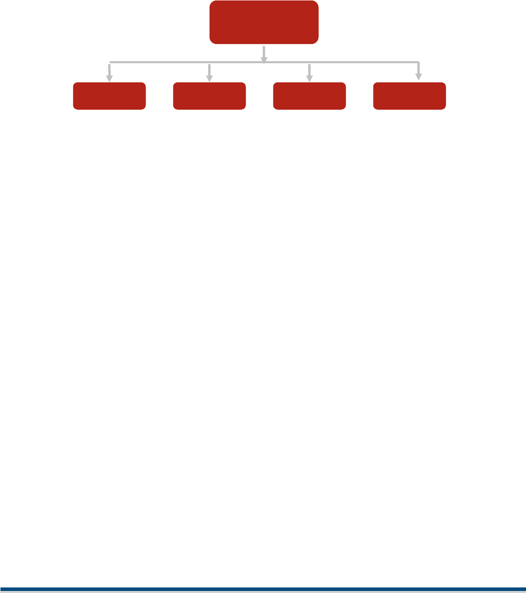
parameters to match the CB951 Access Point(s). Help buttons use a hierarchy based menu structure.
You must enter the Programming Menu first, to select the desired submenu. Each submenu may have
one or more options available. These options are used to assign specific operational characteristics to
the help button. Review the submenus/options before you begin programming. The submenus/options
will vary by help button model.
Enter the Programming Menu
Press and hold the RESET button until the assurance LED flashes one time.
Press and hold the SET button, until the assurance LED flashes two times.
Press and hold the RESET button, until the assurance LED flashes three times.
The help button is now in the Programming Menu mode, proceed to the desired submenu.
Menu-1: Address Programming
Assigns the help button to a corresponding alarm event programmed in the control unit. A help button
address is a four digit number from 0001 to 4095. Leading zeros are required.
After entering the Programming Menu;
Press the SET button one time for Menu-1, RESET once to save.
The assurance LED will flash one time to indicate Menu-1 was selected.
Use SET and RESET to program the 4-digit address as follows;
SET = digits 1-9, RESET = digit 0 and SAVE. Leading zeros are required
For example, programAlarm-0802 as follows:
Press RESET once to represent the zero. (0)
Press SET eight times, RESET once to save. (8)
Press RESET once to represent the zero. (0)
Press SET two times, RESET once to save. (2)
Note: When the RESET button is pressed to save the 4th digit, the assuranceLED will flash to indicate the
address that was entered. The assurance LED will indicate digit zero by a long flash. (approximately 1-
sec.)
Programming
Menu
Address
Learn
Operation
Clone
Menu-1
Menu-2
Menu-3
Menu-7

Technical Document
<Tag Here>
Indyme Solutions, Inc. 8295 Aero Place San Diego, CA 92123 USA +1.858.268.0717 +1.800.829.6141 Page 3 of 7
Menu-2: Learn Mode
Allows the help button to capture the Netcode from another GSF device; (help button or access point).
All help buttons and access points must have the same Netcode to communicate.
After entering the Programming Menu;
Press the SET button two times for Menu-2, RESET once to save.
The LED will flash twice to indicate Menu-2 was selected.
The LED will then begin flashing. ¼ second on, 1 second off. This indicates that the help button is
requesting a Netcode. When the help button receives a Netcode, it will flash the assurance LED
rapidly for approximately 3 seconds and then it will exit Menu-2. If no Netcode is received
within 5 minutes, the help button will exit Menu-2.
Menu-3: Operating Mode
Assigns the help button operating characteristics; timeout duration, RESET signal and number of active
buttons. Although set at the help button, the Operating Mode can be reset and overridden by the
control unit. Operating Modes will vary by help button type, below are the default modes for this help
button.
After entering the Programming Menu;
Press the SET button three times for Menu-3, RESET once to save.
The assurance LED will flash three times to indicate Menu-3 was selected.
Press the SET button to select a Help button Operating Mode: <1, 2, …>, RESET once to save.
The assurance LED will flash to indicate the selected Operating Mode.
Mode 1 - Standard 5-min timeout, No Reset
Press the SET button to trigger the alarm state; the LED will flash for 5 minutes, then extinguish
with no reset sent. The RESET button will send a reset signal for the active channel.
Mode 2 - Standard 30-sec timeout, No Reset
Same as above, with 30-second timeout.
Menu-7: Clone Mode
Allows the help button to broadcast the Netcode to other GSF help buttons. All help buttons and access
points must have the same Netcode to communicate.
After entering the Programming Menu;
Press the SET button seven times for Menu-7, RESET once to save.
The assurance LED will flash seven times to indicate Menu-7 was selected.
The assurance LED will now flash a cadence of 4-pause, 4-pause… etc. The help button will stay
in Clone mode for 5-minutes or until the RESET button, is pressed.
Technical Document
<Tag Here>
Indyme Solutions, Inc. 8295 Aero Place San Diego, CA 92123 USA +1.858.268.0717 +1.800.829.6141 Page 4 of 7
Installation
1. Identify all programming characteristics before you begin programming or installation.
Netcode
Help button Addresses
Help button Modes
2. Program the required parameters into the CB951 Access Points first.
3. Use the first CB951 Access Point to clone the Netcode to all of the help buttons. This will ensure the
same Netcode is being assigned to all devices. You may also clone the Netcode from a known
working help button to all other help buttons. The Netcode cannot be cloned from a help button to
an access point.
4. Program the Alarm Address and Mode of each help button.
5. Install the help button in accordance with store policy, Indyme work order and/or Americans with
Disabilities Act guidelines where applicable.
The CB932 Help button uses two AA-size 1.5-volt alkaline batteries. Always use the same type of battery
for optimum performance. DO NOT use rechargeable batteries in the help button. To replace the
battery, remove the help button from its mounting location. Turn the help button over to the back of
the help button. Remove the old batteries from the battery holders. Install the new alkaline batteries.
The help button does not lose the programmed characteristics when the batteries are removed.
Location Considerations
Help buttons are typically located at cash registers, service counters or other areas in which customers
require assistance. Stores and installers should be aware of the Americans with Disabilities Act (ADA)
requirements for accessibility.
Help buttons use a low powered transmitter, and operate best with a clear line of sight to the nearest
receiver. Tall shelving, merchandise and metal signs can block or reduce the help button signal.
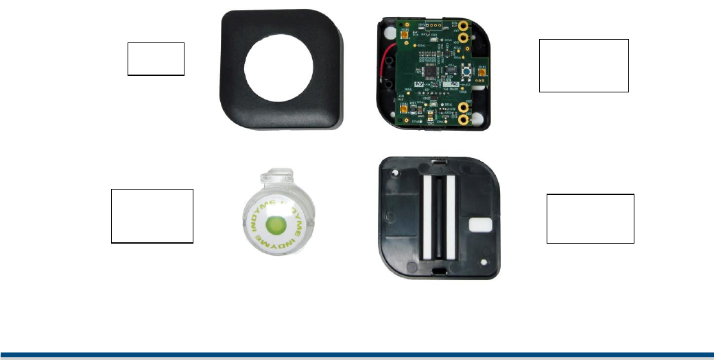
Help Button Assembly
The help button can be disassembled using a flat-blade screwdriver. Find the slot on the outside of the
unit, insert the screwdriver blade and gently twist until the cover pops off. The mounting plate can then
be removed in the same fashion.
Cover
Button
Dome
Electronic
Module
Mounting
Plate
Technical Document
<Tag Here>
Indyme Solutions, Inc. 8295 Aero Place San Diego, CA 92123 USA +1.858.268.0717 +1.800.829.6141 Page 5 of 7
Install the Help button
1. Verify help button placement with the Store Manager and according to provided instructions.
Determine the best mounting method before installing the help button, verify address programming.
Wall Mount
Counter Top Mount
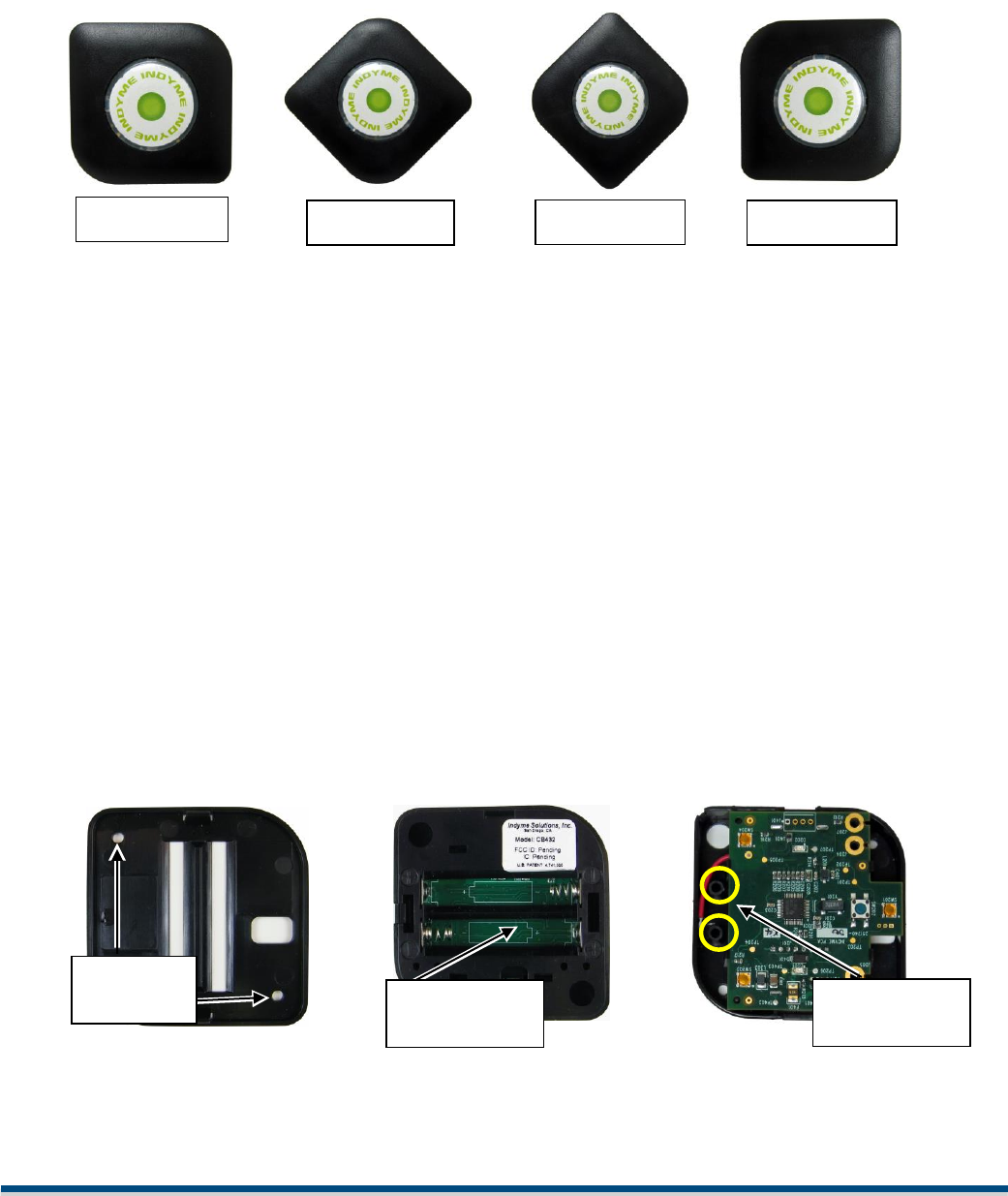
2. The CB932 has four (4) mounting orientation options available; please see pictures below. Choose the
appropriate option for your situation. The CB932 mounting bracket MUST be used for all installations.
Wall Mounting
1. Identify the desired mounting height for the SET button, typically 48” – 54” off the floor.
2. Align the mounting plate at that height and selected orientation.
3. If mounting to glass or a smooth non-porous surface, use the double-sided adhesive ONLY. If mounting
to a solid surface or drywall, mark and drill through the two mounting holes.
4. Insert mounting hardware in the two holes and secure the mounting bracket.
a. wall anchors and screws if drywall or masonry
b. screws only for wood.
5. Insert the batteries and place the mounting holes on the back of the electronic module over the
mounting tabs on the mounting plate; push the module down onto the mounting tabs until it snaps in
place.
6. Insert the desired graphics into the button dome, paying special attention to the final mounting
orientation (see details below).
7. Replace the button dome back into the electronic module by inserting the two (2) posts into the
openings shown below.
8. Position the cover over the assembly and gently press it down until it snaps into place.
9. From the final mounting location, press the SET button on the help button and verify the
appropriate message is broadcast over the desired output device
Orientation F
Orientation C
Orientation P
Mounting
holes
Battery
Compartment
Button Dome
Mounting
Orientation R
Technical Document
<Tag Here>
Indyme Solutions, Inc. 8295 Aero Place San Diego, CA 92123 USA +1.858.268.0717 +1.800.829.6141 Page 6 of 7
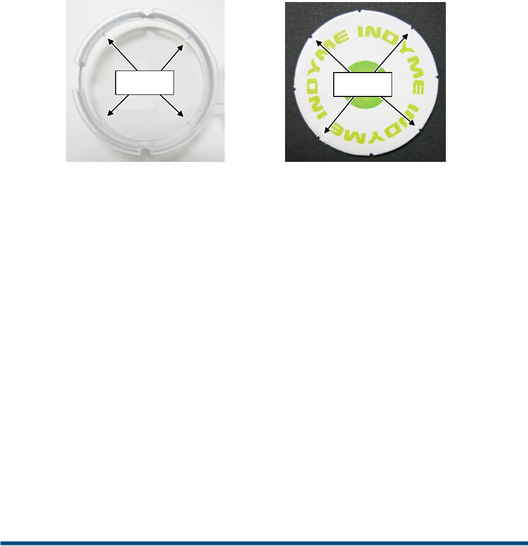
Inserting Graphics into the Button Dome
Included with this help button is a collection of button graphics that can be exchanged prior to
installation. The button dome was designed with alignment tabs inside to allow easy orientation
alignment and installation.
1. Select the desired graphic from the collection.
2. Determine the mounting orientation of the help button from the pictures above; F, C, or P.
3. Remove the default graphic from the button dome using a small screwdriver, being careful not
to scratch the plastic.
4. Align the notches in the new graphic with the tabs inside the button dome, and gently press the
graphic into place. You will want to use your finger to fully seat the graphic until it is completely
smooth against the button dome.
Notches
Tabs

Technical Document
<Tag Here>
Indyme Solutions, Inc. 8295 Aero Place San Diego, CA 92123 USA +1.858.268.0717 +1.800.829.6141 Page 7 of 7
FCC Notice of Compliance
This device complies with Part 15 of the FCC Rules. Operation is subject to the following two conditions:
(1) this device may not cause harmful interference, and (2) this device must accept any interference received,
including interference that may cause undesired operation.
Any changes or modifications not expressly approved by the party responsible for compliance could void the user’s
authority to operate the equipment.
The antenna(s) used for this transmitter must be installed to provide a separation distance of at least 20 cm from
all persons and must not be co-located or operating in conjunction with any other antenna or transmitter.
This equipment has been tested and found to comply with the limits for a Class B digital device, pursuant to part 15
of the FCC Rules. These limits are designed to provide reasonable protection against harmful interference in a
residential installation. This equipment generates, uses, and can radiate radio frequency energy and, if not installed
and used in accordance with the instructions, may cause harmful interference to radio communications. However,
there is no guarantee that interference will not occur in a particular installation. If this equipment does cause
harmful interference to radio or television reception, which can be determined by turning the equipment off and
on, the user is encouraged to try to correct the interference by one or more of the following measures:
Reorient or relocate the receiving antenna.
Increase the separation between the equipment and receiver.
Connect the equipment into an outlet on a circuit different from that to which the receiver is connected.
Consult the dealer or an experienced radio/TV technician for help.
Industry Canada Notice of Compliance
This device complies with Industry Canada licence-exempt RSS standard(s). Operation is subject to the following
two conditions: (1) this device may not cause interference, and (2) this device must accept any interference,
including interference that may cause undesired operation of the device.
Any changes or modifications not expressly approved by the party responsible for compliance could void the user’s
authority to operate the equipment.
This Class B digital apparatus complies with Canadian ICES-003.
Le présent appareil est conforme aux CNR d'Industrie Canada applicables aux appareils radioexempts de licence.
L'exploitation est autorisée aux deux conditions suivantes : (1) l'appareil ne doit pas produire de brouillage, et (2)
l'utilisateur de l'appareil doit accepter tout brouillage radioélectrique subi, même si le brouillage est susceptible
d'en compromettre le fonctionnement.
Les changements ou modifications non approuvés expressément par la partie responsable de la conformité
pourrait annuler l'autorité de l'utilisateur à faire fonctionner l'équipement.
Cet appareil numérique de la classe B est conforme à la norme NMB-003 du Canada.