Indyme Solutions CU5300 WIRELESS CONTROL UNIT User Manual BRD Lite
Indyme Solutions, Inc WIRELESS CONTROL UNIT BRD Lite
Users Manual

CU5300/5303W Control Unit
Technical Description Document
TDD
V1.0.1(draft)
06/22/2017

2
INDYME CONFIDENTIAL FOR INTERNAL USE ONLY
DRAFT

3
CONTENTS
Glossary .................................................................................................................................. 5
Introduction ............................................................................................................................ 5
Port Overview ......................................................................................................................... 7
Functional Description ............................................................................................................. 8
1. Overview ............................................................................................................................................. 8
2. Startup Sequence ................................................................................................................................ 8
Supported Functions ............................................................................................................... 8
1. Input Compatibility ....................................................................................................................... 8
2. Capacity 9
3. Ethernet 9
4. Universal Serial Bus (USB) ................................................................................................................... 9
5. Audio Ports .......................................................................................................................................... 9
6. Controls and Indicators ....................................................................................................................... 10
7. Shopper and Director Call Box Support .............................................................................................. 10
8. SmartSense Device Support ................................................................................................................ 10
9. Scheduled Messaging (Promos) .......................................................................................................... 11
10. Email Output ..................................................................................................................................... 11
11. Two-Way Radio Support ................................................................................................................... 11
12. Graphical User Interface (GUI) .......................................................................................................... 11
13. Activity Data ...................................................................................................................................... 11
14. SmartPortal Support ......................................................................................................................... 12
15. Power 12
16. Packaging........................................................................................................................................... 12
17. Virtual Private Network (VPN) Support ............................................................................................. 12
18. MAC Address ..................................................................................................................................... 12
19. FCC and IC Statements ...................................................................................................................... 13
References and Related Documents ......................................................................................... 14

4
Revision History
Version #
Date
Author(s)
Summary of Changes
1.0
12/22/2016
Mike Sheppard
Initial draft.
1.0.1
06/22/17
Joe Silberman
Revised Draft including augmented details as
requested by TCB
Reviewers
Name
Organizational Role
Reviewed Date
Derek Morikawa
VP Engineering
Ron Weiland
Senior Software Engineer
Greg King
Senior Hardware Engineer

5
Approvers
Name
Project Role
Approval Date
Derek Morikawa
Technical Sponsor
GLOSSARY
Abbreviation/Acronym
Term
Description
CU5300
Control Unit
Smart Control Appliance
CU5303W
Control Unit
Smart Control Appliance for Walgreens
INTRODUCTION
The CU5300/5303W is the next generation control platform for the Smart Response System. The controller
features a configurable event processing engine, message library, and fully integrated 900 MHz RF
transceiver to facilitate communication with shopper help buttons and Global Solution Family (GSF) Smart
Sense devices.
6
CU5303W Connect RS
CRS (Walgreens)
CU5300 Connect RT
CRT
CU5301 Connect RV
CRV (Kohls)
7
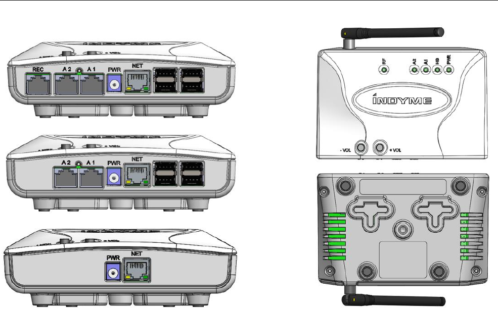
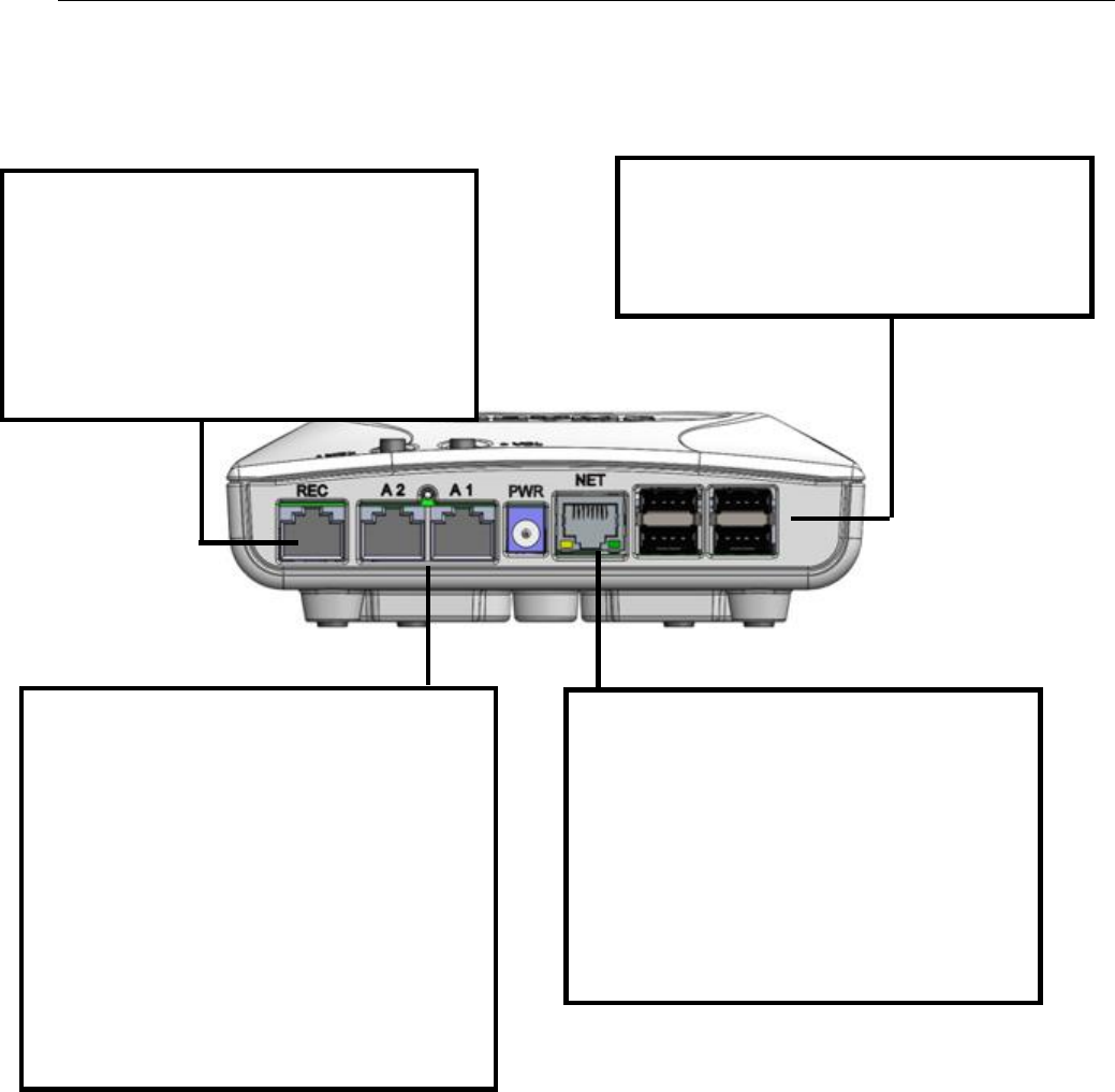
PORT OVERVIEW
The RECEIVER Port is used to connect the
Control Unit to 303MHz CB451 Call Box
Receivers ONLY. The RECEIVER Port provides
+12VDC to support a maximum of (4) CB451
Receivers. CB451 Call Box Receivers are
connected using an RJ45 modular plug and
CAT-5 cable
The A1 and A2 indicators are multi-color
LEDs used to indicate the status of the two
AUDIO Ports. Each LED will light up RED or
GREEN to indicate the status of the
corresponding Audio Port. Both LEDs are on
during normal operations. A1 is normally
GREEN but turns RED when a busy signal is
detected on AUDIO Port 1. A2 is normally
GREEN when connected to an Indyme Paging
Transmitter, but turns RED when a busy
signal is detected, or if the Paging
Transmitter is disconnected.
The USB Ports are NON-STANDARD
interfaces. They are not intended for
peripherals and are used for software
upgrades ONLY.
The NET Port is the primary network
interface to the 900 MHz CB951 Access Point,
a network based receiver. The CB951
receives signals from Indyme Global Smart
Sense devices and sends those signals to the
Control Unit via the Local Area Net on the
NET Port. It is configured as the main
Ethernet Port when the Control Unit is
connected to a Local Area Network.

8
FUNCTIONAL DESCRIPTION
1. Overview
The CU5300 is the latest hardware control unit developed by Indyme to be the central interface for the Global
Solution Family (GSF) of Smart Sense Devices, legacy Call Boxes, and Shopper Help Buttons. The
CU5300/5302W offers an easy to configure and install solution for rapid deployment of a completely integrated
system offering.
The CU5300 accepts triggers from GSF help buttons and Smart Sense devices over the network via CB451 or
CB951 transceivers. The default configuration provides support for ten (10) call boxes and four (4) CB451
receivers.
Once configured, the controller provides the alarm engine and messaging inputs for connected GSF and
Director call boxes, and Smart Sense devices.
2. Startup Sequence
The CU5300 startup sequence begins from a bootloader located in a partition on a local SD card. This is the
code that runs prior to the application software and initiates the Linux kernel in the controller. After the power
up sequence completes, a properly configured CU5300 will sit in standby mode until it receives an input from
the network or via a web-based GUI using a compatible web browser. All GUI functionality resides within the
control unit and is not downloaded by the web browser.
SUPPORTED FUNCTIONS
1. Input Compatibility
The CU5300/5303W
• Accepts event triggers from a network device (POS terminal) or wireless device (shopper help button)
• Accepts event triggers from GSF help buttons, Smart Sense devices and QuickLink over the Ethernet
port

9
2. Capacity
The CU5300/5303W
• Supports a minimum of 4,000 wireless device capability (i.e., 0001 – 3999)
• Supports a minimum of 1,000 Ethernet inputs that are separated from the wireless addresses
• Supports a minimum of 60 minutes of audio storage
3. RF Output
The CU5300/5303W
• Frequency Range: 868.175 - 869.675 MHz and 918.1 – 925.0 MHz
• Modulation Type: 2-GMSK frequency hopping spread spectrum
• Antenna Type: Omni-Directional dipole, +2dBi maximum gain, RP-SMA connector
4. Ethernet
The CU5300/5303W
• Supports a standard 802.3 10/100 Ethernet connection.
• Supports 802.3af and 802.3at
• Uses a standard RJ45 connector with indicator LEDs for troubleshooting.
• Appliance is able to accommodate fixed and DHCP IP addressing.
5. Universal Serial Bus (USB)
• Two (2) USB connections are available on the controller.
• The USB ports are secured to minimize risk exposure.
• The USB ports will be used for various system and variable updates only.
6. Audio Ports
Direct Audio 1
• Direct Audio 1 is typically used to connect to a Public Address (P.A.) system.
• Direct Audio 1 has Audio In, Audio Out, Busy In, and a seize out (same as the Direct Audio 1 port on
the CLX/CLT).
• Direct Audio 1 is a standard RJ45 with the same pinouts as current CU’s
• Direct Audio 1 has an Input and an Output allowing another audio source to be looped through the
appliance.
• The appliance is able to switch between the external audio source (Audio In) and the internal audio
output as needed.
• The powered down and default mode allows the audio to pass from Audio In to Audio Out.
• The appliance is able to monitor Audio In for busy status (VOX). This feature is selectable on/off.
Direct Audio 2
• Direct Audio 2 is typically used to connect to an Indyme PT transceiver.

10
• Direct Audio 2 has an Audio In, Audio Out, Busy In, and a PTT out (same as the Direct Audio 2 port on
the CLX/CLT).
• Direct Audio 2 is a standard RJ45 with the same pinouts as current CU’s.
• This port is used with existing PT14 and PT14-1 units, and will be 100% reverse compatible.
7. Controls and Indicators
• Direct Audio 1 has a bi-colored status LED
• Green = Ready
• Red = Busy (Vox mode only)
• Amber = In use (audio outputting)
• Direct Audio 2 has a bi-colored status LED
• Green = Ready
• Red = Busy (carrier presence contact or audio input presence, depending on mode, e.g., PT14-4 vs.
PT14-1)
• Amber = In use (PTT seize)
• Power/Heartbeat/Error has a bi-colored status LED
• Flashing Green = Good
• Flashing Red = Error
• Volume control consists of two (2) push buttons (same/similar to CLX/CLT)
• Used to select Audio 1 or Audio 2
• Used to increase or decrease volume levels
• Volume level indicated on Direct Audio 1 or Direct Audio 2 LED while adjusting
• Can use same method used on CLX/CLT, where cadence of flashing LED indicates volume level.
• Slow flash = low volume
• Rapid flash = high volume
• There is also a means to adjust the volume for Audio 1 and Audio 2 independently via the GUI. This
allows the user to adjust using a numbers scale as opposed to the flash rate on the LED.
8. Shopper and Director Call Box Support
• All current (as of EFS release date) Shopper & Director call boxes are supported in the CU5300/5303W.
• The default configuration will support up to ten (10) call boxes.
• A License key or other method of unlocking features is not currently supported, but will be
implemented in a future sw release for additional shopper call box support.
9. SmartSense Device Support
• All current (as of TDD release date) GSF SmartSense devices are supported in the CU5300/5303W.
• The default configuration supports up to ten (10) devices.

11
10. Scheduled Messaging (Promos)
• By default, Interval promos are disabled.
• By Default, Day Time promos are disabled.
• By default, Time Of Day promos are disabled.
11. Email Output
• By default, definable email output addresses are limited to five (5).
• In future sw releases, a License key or other method of unlocking features will be required to enable
additional functionality.
12. Two-Way Radio Support
• By default, two-way radio output is supported by the CU5300/5303W using the following:
• PT14-4, 4 channel transceiver
• PT14-1, single channel transceiver
13. Graphical User Interface (GUI)
• A GUI is available via the Ethernet connection for configuration of the CU5300/5303W variables.
• The GUI is presented in an easy to follow, intuitive manner so that a non-technical end user, such as
store manager, can configure the system.
• The CU5300/5303W GUI has many of the same components for configuring the variables that are
currently available via the CLX/CLT units.
• Multiple languages are supported by the CU5300/5303W.
• English
• Spanish
• German
• French
• Portuguese (Brazil)
• The CU5300/5303W supports the following Browsers:
• IE
• Chrome
• Safari
• FireFox
• Audio messages are implemented in a format that can readily be recorded with a standard Windows
or Mac PC.
• The capability to Upload, Listen, and Delete audio messages is managed via the GUI.
14. Activity Data
• The unit retains all activity data in a .csv file
• The unit has the capability of pushing the data to a designated location (URL) including log-in
credentials. (ftp, sftp)
• The GUI provides an easy way to download the .csv file to a local or networked PC.

12
15. SmartPortal Support
• The CU5300/5303W is fully supported by Smart Portal
• Smart Portal is capable of managing:
• Software updates (Full Linux upgrade not available with CU Release 1.0)!
• Configuration management
• Data collection
• Message management
16. Power
• The CU5300/5303W power supply:
o Input voltage range 120/240 VAC 50-60 Hz, 0.4 Amps maximum
o Ouput voltage +12 VDC at 1.25 Amps
• The unit supplies enough power to support multiple GSF transceivers, and up to four (4) 303 MHz
receivers.
17. Packaging
The device enclosure will be a composite material with dark gray color.
Size:
• Dimensions: 6.0” W x 4.0” D x 1.0” H
• Weight: 0.597 lbs
Color:
• Dark Gray
Mounting:
• Bulkhead: Keyholes provide a clean installation to standard bulkhead mount.
• Ceiling mounting: Optional ceiling mount hardware is available.
• Shelf mounting - optional feet for countertop or shelf mounting.
• Bulkhead mounting orientation will be with connectors either positioned down or off to one side.
• Rack mounting
18. Virtual Private Network (VPN) Support
• The CU5300/5303W supports a secure virtual private network (VPN) topology and allows only
authenticated remote access using tunneling protocols and encryption techniques to prevent access
to, or disclosure of private information.
19. MAC Address
• A media access control address (MAC address) is assigned to each unit as a unique identifier for
communications at the data link layer of a network segment.

13
20. FCC and IC Statements
FCC statements:
“This device complies with part 15 of the FCC Rules. Operation is subject to the following two conditions: (1)
This device may not cause harmful interference, and (2) this device must accept any interference received,
including interference that may cause undesired operation.”
“Caution: Changes or modifications not expressly approved by the party responsible for compliance could void
the user's authority to operate this equipment.”
If the device has removable antennas then a list of the antennas that may be used with the device must be
included in the user manual. The list should identify the type of antenna, impedance (usually 50 ohms), and
the maximum gain in dBi.
IC Statements:
“This device complies with Industry Canada licence-exempt RSS standard(s). Operation is subject to the
following two conditions: (1) this device may not cause interference, and (2) this device must accept any
interference, including interference that may cause undesired operation of the device.”
“Cet appareil est conforme avec Industrie Canada exempts de licence standard RSS (s). Son fonctionnement
est soumis aux deux conditions suivantes: (1) cet appareil ne doit pas provoquer d'interférences et (2) cet
appareil doit accepter toute interférence, y compris celles pouvant causer un mauvais fonctionnement de
l'appareil.”
Health Canada RF Exposure Warning Statement
“This device complies with Health Canada’s Safety Code. The installer of this device should
ensure that RF radiation is not emitted in excess of the Health Canada’s requirement. Information can
be obtained at http://www.hc-sc.gc.ca/ewh-semt/pubs/radiation/radio_guide-lignes_direct/index-
eng.php”
French version:
“Cet appareil est conforme avec Santé Canada Code de sécurité 6. Le
programme d ’installation de cet appareil doit s’ assurer que les rayonnements
RF n’est pas émis au-delà de I’exigence de Santé Canada. Les informations

14
peuvent être obtenues:
http://www.hc-sc.gc.ca/ewh-semt/pubs/radiation/radio_guide-lignes_direct/index-fra.php”
REFERENCES AND RELATED DOCUMENTS
Title
Link
MPR
EFS
http://sharepoint1/prodmgmt/MPRs/Forms/AllItems
http://sharepoint1/ProjectMgmt/Engineering%20Functional%20Specifications%20EF
S/Forms/AllItems.aspx