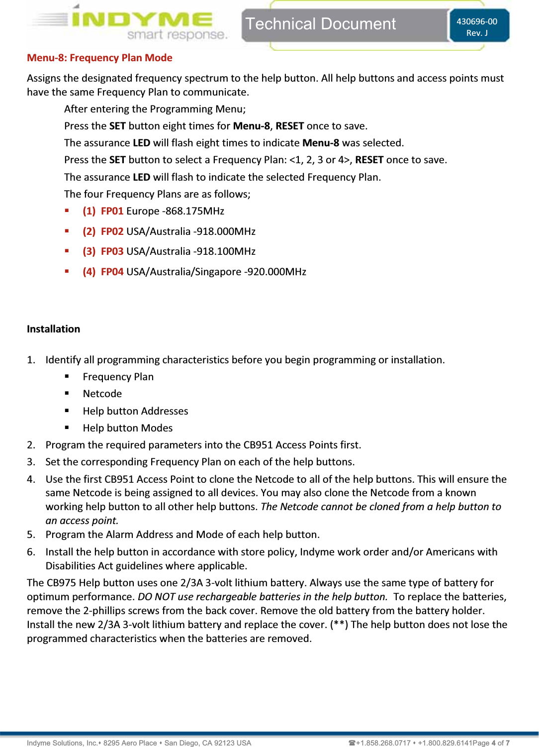
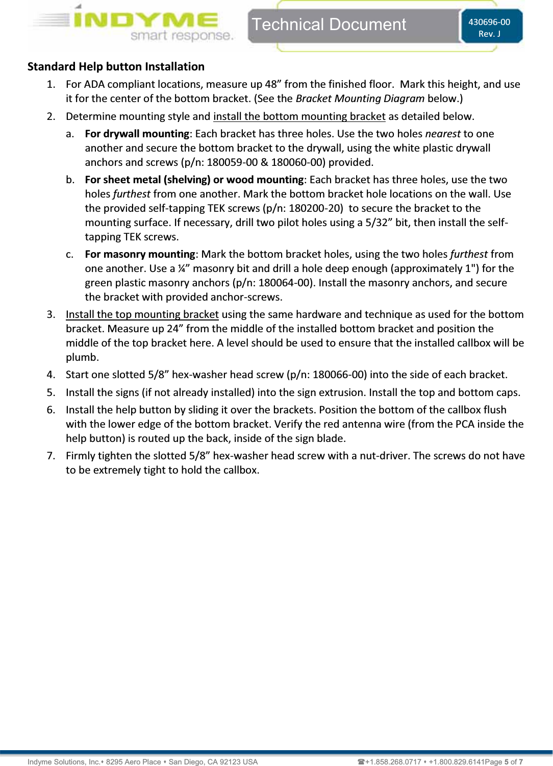
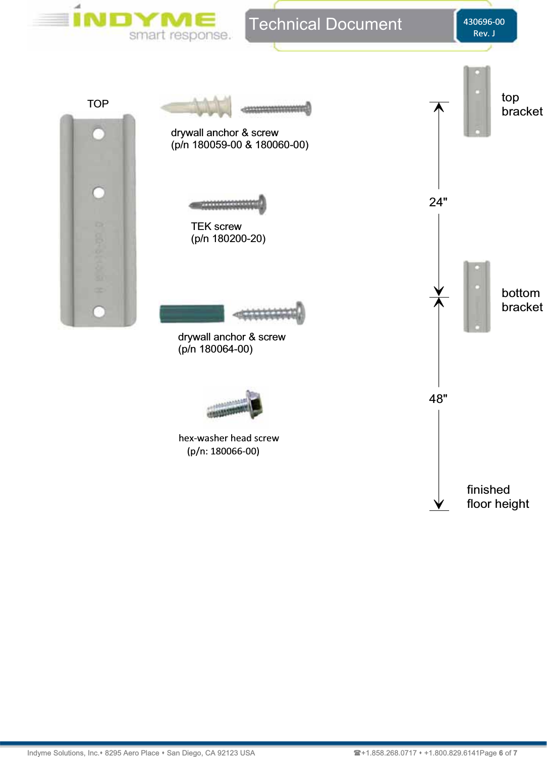
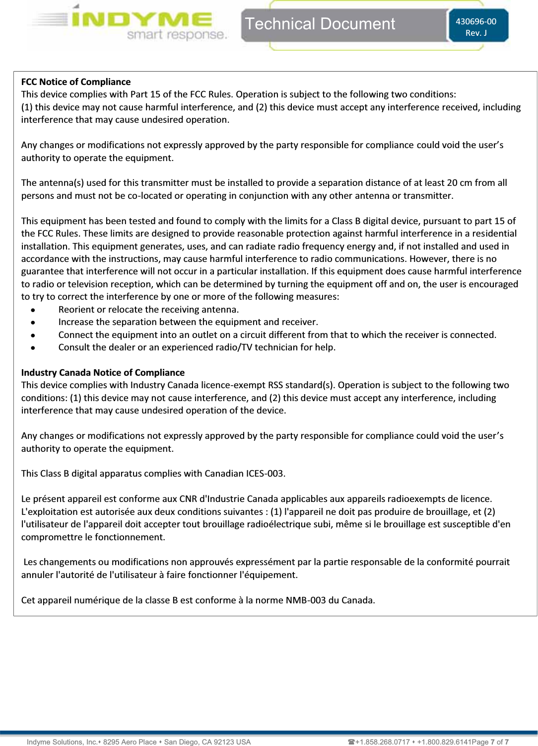
Indyme Solutions TYPEA2 Help Button User Manual

Indyme Solutions, Inc Help Button

user manual

   Technical Document  430715-03 Rev. G Indyme Solutions, Inc. 8295 Aero Place  San Diego, CA 92123 USA                                                            +1.858.268.0717  +1.800.829.6141Page 1 of 5 CB911 Wireless Director Help button                        Programming and Installation Instructions Overview The CB911 is a member of the Global Solutions Family. Indyme GSF products operate in the 800MHz ʹ 900MHz frequency spectrum. The CB911 is a 1-button, GSF, Director Help button designed for use at POS, Customer Service or cash register locations. GSF Help buttons are designed to communicate with a GSF Access Point. GSF products are not compatible with legacy devices   Programming Parameters GSF products MUST be properly programmed to establish communication. Programming parameters MUST match your configuration. The default settings are for testing purposes only and should not be used. Failure to properly program your help button and access point will prevent your devices from working.   GSF Help buttons have four primary programming parameters; Frequency Plan, Netcode, Address and Operating Mode. These MUST be programmed in the correct order to establish communication and ensure proper operation. Identify the parameters for your configuration before you begin programming.   Using the programming instructions below set the following parameters in order.   Frequency Plan ʹ defines the frequency for your GSF devices.     Netcode ʹ unique identification code for the installation environment.  Address ʹ alarm number associated with a control unit alarm event.  Operating Mode ʹ defines how the help button will respond when activated.  Programming a help button requires a series of button presses. The specific buttons vary by help button type. On the CB911, SET is ƚŚĞ͞PRESS HERE͟ďƵƚƚŽŶand RESET is a small circle to the right of the Indyme name at the bottom of the help button. The assurance LED is red and is located next to the SET button. This LED will flash during programming to indicate your progress.   Frequency Plan  *FP03 USA/Australia -918.100MHz Netcode *00000001 Address *0001 Operating Mode  *1 * Default parameters are for testing purposes only. CB911 LED RESET
   Technical Document  430715-03 Rev. G Indyme Solutions, Inc. 8295 Aero Place  San Diego, CA 92123 USA                                                            +1.858.268.0717  +1.800.829.6141Page 2 of 5 GSF Help button Programming GSF Help buttons function in the 800MHz ʹ 900MHz frequency spectrum. These wireless transceivers, communicate with the CB951 Access Point. Each help button MUST be programmed with the correct parameters to match the CB951 Access Point(s). Help buttons use a hierarchy based menu structure. You must enter the Programming Menu first, to select the desired submenu. Each submenu may have one or more options available. These options are used to assign specific operational characteristics to the help button. Review the submenus/options before you begin programming. The submenus/options will vary by help button model.            Enter the Programming Menu Press and hold the RESET button until the assurance LED flashes one time. Press and hold the SET button, until the assurance LED flashes two times. Press and hold the RESET button, until the assurance LED flashes three times. The help button is now in the Programming Menu mode, proceed to the desired submenu. (***)  Menu-1:  Address Programming Assigns the help button to a corresponding alarm event programmed in the control unit. A help button address is a four digit number from 0001 to 4095. Leading zeros are required.  After entering the Programming Menu; Press the SET button one time for Menu-1, RESET once to save. The assurance LED will flash one time to indicate Menu-1 was selected. Use SET and RESET to program the 4-digit address as follows; SET = digits 1-9, RESET = digit 0 and SAVE. Leading zeros are required  For example, program Alarm-0802 as follows:  Press RESET once to represent the zero. (0)  Press SET eight times, RESET once to save. (8)  Press RESET once to represent the zero. (0)  Press SET two times, RESET once to save. (2) Note: When the RESET button is pressed to save the 4th digit, the assurance LED will flash to indicate the address that was entered. The assurance LED will indicate digit zero by a long flash. (approximately 1-sec.)  Programming Menu Address  Learn  Operation  Clone  Frequency Menu-1  Menu-2  Menu-3  Menu-7  Menu-8
   Technical Document  430715-03 Rev. G Indyme Solutions, Inc. 8295 Aero Place  San Diego, CA 92123 USA                                                            +1.858.268.0717  +1.800.829.6141Page 3 of 5 Menu-2:  Learn Mode Allows the help button to capture the Netcode from another GSF device; (help button or access point). All help buttons and access points must have the same Netcode to communicate. After entering the Programming Menu; Press the SET button two times for Menu-2, RESET once to save. The LED will flash twice to indicate Menu-2 was selected. The LED will then begin flashing. ¼ second on, 1 second off. This indicates that the help button is requesting a Netcode. When the help button receives a Netcode, it will flash the assurance LED rapidly for approximately 3 seconds and then it will exit Menu-2. If no Netcode is received within 5 minutes, the help button will exit Menu-2.  Menu-3:  Operating Mode Assigns the help button operating characteristics; timeout duration, RESET signal and number of active buttons. Although set at the help button, the Operating Mode can be reset and overridden by the control unit. Operating Modes will vary by help button type, below are the default modes for this help button. After entering the Programming Menu; Press the SET button three times for Menu-3, RESET once to save. The assurance LED will flash three times to indicate Menu-3 was selected. Press the SET button to select a Help button Operating Mode: <1, 2>, RESET once to save. The assurance LED will flash to indicate the selected Operating Mode.   Mode 1 - Standard 8-min timeout, No Reset Press any channel button to trigger the alarm state; the corresponding LED(s) will flash. The LED will flash for 8 minutes, then extinguish with no reset sent. The RESET button will sent a reset signal for all active channels.    Mode 2 - Standard 30-sec timeout, No Reset Press any channel button to trigger the alarm state; the corresponding LED(s) will flash. The LED will flash for 30 seconds, then extinguish with no reset sent. The RESET button will sent a reset signal for all active channels.   Menu-7: Clone Mode Allows the help button to broadcast the Netcode to other GSF help buttons. All help buttons and access points must have the same Netcode to communicate. After entering the Programming Menu; Press the SET button seven times for Menu-7, RESET once to save. The assurance LED will flash seven times to indicate Menu-7 was selected. The assurance LED will now flash a cadence of 4-pause, 4-pause͙ etc. The help button will stay in Clone mode for 5-minutes or until the RESET button, is pressed.
   Technical Document  430715-03 Rev. G Indyme Solutions, Inc. 8295 Aero Place  San Diego, CA 92123 USA                                                            +1.858.268.0717  +1.800.829.6141Page 4 of 5 Menu-8: Frequency Plan Mode Assigns the designated frequency spectrum to the help button. All help buttons and access points must have the same Frequency Plan to communicate.  After entering the Programming Menu; Press the SET button eight times for Menu-8, RESET once to save. The assurance LED will flash eight times to indicate Menu-8 was selected. Press the SET button to select a Frequency Plan: <1, 2, 3 or 4>, RESET once to save. The assurance LED will flash to indicate the selected Frequency Plan. The four Frequency Plans are as follows;  (1)  FP01 Europe -868.175MHz  (2)  FP02 USA/Australia -918.000MHz  (3)  FP03 USA/Australia -918.100MHz  (4)  FP04 USA/Australia/Singapore -920.000MHz Installation The CB911 help button ships with Velcro strips and double-sided tape. To mount the help button, thoroughly clean the mounting surface with alcohol, removing all dirt from the mounting surface. Using the desired mounting adhesive, place one piece on the back of the help button. Remove the protective backing from the adhesive press the help button firmly into position ʹ typically located near a register or telephone at a checkout counter or service desk.   1. Identify all programming characteristics before you begin programming or installation.  Frequency Plan  Netcode  Help button Addresses   Help button Modes 2. Program the required parameters into the CB951 Access Points first.  3. Set the corresponding Frequency Plan on each of the help buttons.  4. Use the first CB951 Access Point to clone the Netcode to all of the help buttons. This will ensure the same Netcode is being assigned to all devices. You may also clone the Netcode from a known working help button to all other help buttons. 5. Program the Alarm Address and Mode of each help button. 6. The help button will automatically exit any programming menu if no buttons are pressed for 30-seconds. 7. Install the help button in accordance with store policy, Indyme work order and/or Americans with Disabilities Act guidelines where applicable.  The CB911 Help button uses one 2/3A 3-volt lithium battery. Always use the same type of battery for optimum performance.  DO NOT use rechargeable batteries in the help button. To replace the batteries, remove the 2-philips screws from the back cover. Remove the old battery from the battery holder. Install the new 2/3A 3-volt lithium battery and replace the cover.  The help button does not lose the programmed characteristics when the batteries are removed.
   Technical Document  430715-03 Rev. G Indyme Solutions, Inc. 8295 Aero Place  San Diego, CA 92123 USA                                                            +1.858.268.0717  +1.800.829.6141Page 5 of 5   FCC Notice of Compliance  This device complies with Part 15 of the FCC Rules. Operation is subject to the following two conditions:  (1) this device may not cause harmful interference, and (2) this device must accept any interference received, including interference that may cause undesired operation.   Any changes or modifications not expressly approved by the party responsible for compliance ĐŽƵůĚǀŽŝĚƚŚĞƵƐĞƌ͛Ɛauthority to operate the equipment.  The antenna(s) used for this transmitter must be installed to provide a separation distance of at least 20 cm from all persons and must not be co-located or operating in conjunction with any other antenna or transmitter.  This equipment has been tested and found to comply with the limits for a Class B digital device, pursuant to part 15 of the FCC Rules. These limits are designed to provide reasonable protection against harmful interference in a residential installation. This equipment generates, uses, and can radiate radio frequency energy and, if not installed and used in accordance with the instructions, may cause harmful interference to radio communications. However, there is no guarantee that interference will not occur in a particular installation. If this equipment does cause harmful interference to radio or television reception, which can be determined by turning the equipment off and on, the user is encouraged to try to correct the interference by one or more of the following measures: x Reorient or relocate the receiving antenna. x Increase the separation between the equipment and receiver. x Connect the equipment into an outlet on a circuit different from that to which the receiver is connected. x Consult the dealer or an experienced radio/TV technician for help.   Industry Canada Notice of Compliance This device complies with Industry Canada licence-exempt RSS standard(s). Operation is subject to the following two conditions: (1) this device may not cause interference, and (2) this device must accept any interference, including interference that may cause undesired operation of the device.  Any changes or modifications not expressly approved by the party responsible for compliance could void the user͛Ɛauthority to operate the equipment.  This Class B digital apparatus complies with Canadian ICES-003.  Le présent appareil est conforme aux CNR d'Industrie Canada applicables aux appareils radioexempts de licence. L'exploitation est autorisée aux deux conditions suivantes : (1) l'appareil ne doit pas produire de brouillage, et (2) l'utilisateur de l'appareil doit accepter tout brouillage radioélectrique subi, même si le brouillage est susceptible d'en compromettre le fonctionnement.   Les changements ou modifications non approuvés expressément par la partie responsable de la conformité pourrait annuler l'autorité de l'utilisateur à faire fonctionner l'équipement.  Cet appareil numérique de la classe B est conforme à la norme NMB-003 du Canada.
  Technical Document  430693-00 Rev. K Indyme Solutions, Inc. 8295 Aero Place  San Diego, CA 92123 USA                          +1.858.268.0717  +1.800.829.6141Page 1 of 5  CB914 Wireless Director Help Button Programming and Installation Instructions  Introduction The CB914 is a member of the Global Solutions Family. Indyme GSF products operate in the 800MHz ʹ 900MHz frequency spectrum. The CB914 is a 4-button, GSF, Director Help Button designed for use at customer service or cash register locations. GSF Help Buttons communicate with an Indyme GSF Access Point. GSF products are not compatible with legacy devices  Programming Parameters GSF products MUST be properly programmed to establish communication. Programming parameters MUST match your configuration. The default settings are for testing purposes only and should not be used. Failure to properly program your help button and access point will prevent your devices from working.   GSF help buttons have four primary programming parameters; Frequency Plan, Netcode, Address and Operating Mode. These MUST be programmed in the correct order to establish communication and ensure proper operation. Identify the parameters for your configuration before you begin programming.   Using the programming instructions below set the following parameters in order.  x Frequency Plan ʹ defines the frequency for your GSF devices.    x Netcode ʹ unique identification code for the installation environment. x Address ʹ alarm number associated with a control unit alarm event. x Operating Mode ʹ defines how the help button will respond when activated.  Programming a help button requires a series of button presses. The specific buttons vary by help button type. On the CB914, SET is BUTTON-1 and RESET is a small circle below button-4. The assurance LED is red and is located next to the SET button. This LED will flash during programming to indicate your progress.      Frequency Plan  *FP03 USA/Australia -918.100MHz Netcode *00000001 Address *0001 Operating Mode  *1 * Default parameters are for testing purposes only. RESET LED  CB914
  Technical Document  <Tag Here> Indyme Solutions, Inc. 8295 Aero Place  San Diego, CA 92123 USA                          +1.858.268.0717  +1.800.829.6141  Page 2 of 5 GSF Help Button Programming GSF help buttons function in the 800MHz ʹ 900MHz frequency spectrum. These wireless transceivers, communicate with the CB951 Access Point. Each help button MUST be programmed with the correct parameters to match the CB951 Access Point(s). Help buttons use a hierarchy based menu structure. You must enter the Programming Menu first, to select the desired submenu. Each submenu may have one or more options available. These options are used to assign specific operational characteristics to the help button. Review the submenus/options before you begin programming. The submenus/options will vary by help button model.          Enter the Programming Menu Press and hold the RESET button until the assurance LED flashes one time. Press and hold the SET button, until the assurance LED flashes two times. Press and hold the RESET button, until the assurance LED flashes three times. The help button is now in the Programming Menu mode, proceed to the desired submenu. The help button will automatically exit any programming menu if no buttons are pressed for 30-seconds.  Menu-1: Address Programming Assigns the help button to a corresponding alarm event programmed in the control unit. A help button address is a four digit number from 0001 to 4095. Leading zeros are required.  After entering the Programming Menu; Press the SET button one time for Menu-1, RESET once to save. The assurance LED will flash one time to indicate Menu-1 was selected. Use SET and RESET to program the 4-digit address as follows; SET = digits 1-9, RESET = digit 0 and SAVE. Leading zeros are required  For example, program Alarm-0802 as follows: x Press RESET once to represent the zero. (0) x Press SET eight times, RESET once to save. (8) x Press RESET once to represent the zero. (0) x Press SET two times, RESET once to save. (2) Note: When the RESET button is pressed to save the 4th digit, the assurance LED will flash to indicate the address that was entered. The assurance LED will indicate digit zero by a long flash. (approximately 1-sec.)    Programming Menu Address  Learn  Operation  Clone  Frequency Menu-1  Menu-2  Menu-3  Menu-7  Menu-8
  Technical Document  <Tag Here> Indyme Solutions, Inc. 8295 Aero Place  San Diego, CA 92123 USA                          +1.858.268.0717  +1.800.829.6141  Page 3 of 5 Menu-2: Learn Mode Allows the help button to capture the Netcode from another GSF device; (help button or access point). All help buttons and access points must have the same Netcode to communicate. After entering the Programming Menu; Press the SET button two times for Menu-2, RESET once to save. The LED will flash twice to indicate Menu-2 was selected. The LED will then begin flashing. ¼ second on, 1 second off. This indicates that the help button is requesting a Netcode. When the help button receives a Netcode, it will flash the assurance LED rapidly for approximately 3 seconds and then it will exit Menu-2. If no Netcode is received within 5 minutes, the help button will exit Menu-2.  Menu-3: Operating Mode Assigns the help button operating characteristics; timeout duration, RESET signal and number of active buttons. Although set at the help button, the Operating Mode can be reset and overridden by the control unit. Operating Modes will vary by help button type, below are the default modes for this help button.  After entering the Programming Menu; Press the SET button three times for Menu-3, RESET once to save. The assurance LED will flash three times to indicate Menu-3 was selected. Press the SET button to select a Help button Operating Mode: <1, 2, 10>, RESET once to save. The assurance LED will flash to indicate the selected Operating Mode.  x Mode 1 - 8-min timeout, No Reset Press any channel button to trigger the alarm state; the corresponding LED(s) will flash. The LED will flash for 8 minutes, then extinguish with no reset sent. The external input is a valid momentary trigger of channel-4. If the trigger is removed, no reset is sent. The RESET button will sent a reset signal for all active channels.  x Mode 2 - 30-sec timeout, No Reset Press any channel button to trigger the alarm state; the corresponding LED(s) will flash. The LED will flash for 30 seconds, then extinguish with no reset sent. The external input is a valid momentary trigger of channel-4. If the trigger is removed, no reset is sent. The RESET button will sent a reset signal for all active channels. x Mode 10 ʹ Site Survey (4-Button GSF Help buttons ONLY) WƌĞƐƐĂŶLJŽĨƚŚĞϰďƵƚƚŽŶƐƚŽĂĐƚŝǀĂƚĞƚŚĞƐŝƚĞƐƵƌǀĞLJ͘>͛ƐϮ͕ϯ͕4 turn on as a 3-second ƚŝŵĞƌ͕ĐŽƵŶƚŝŶŐĚŽǁŶďĞĨŽƌĞƚŚĞƐƚĂƌƚŽĨƚŚĞƐƵƌǀĞLJ͘dŚĞ>͛ƐǁŝůůƚƵƌŶŽĨĨ͕ŽŶĞƉĞƌƐĞĐŽŶĚ͕(2-3-ϰͿƚŽŝŶĚŝĐĂƚĞƚŚĞĐŽƵŶƚĚŽǁŶ͘tŚĞŶĂůůϯ>͛ƐĂƌĞŽĨĨ͕ƚŚĞƐƵƌǀĞLJǁŝůůďĞŐŝŶ͘ LED 1 will begin flashing to indicate that the help button is searching for the strongest AP with the correct Netcode.  When the strongest AP is found, the help button will send 10 pings to that AP and calculate the average RSSI. (Received Signal Strength Indication)  The following table describes the LED results.  >͛Ɛ Reading 1,2,3,4 On  Excellent - RSSI is -70 dBm or better 2,3,4 On  Good - RSSI is -80 to -71 dBm 3,4 On  Fair - RSSI is -88 to-81 dBm 4 On  Poor - RSSI is -89 dBm or worse 4 Flashing  Not connected to an AP
  Technical Document  <Tag Here> Indyme Solutions, Inc. 8295 Aero Place  San Diego, CA 92123 USA                          +1.858.268.0717  +1.800.829.6141  Page 4 of 5 Menu-7: Clone Mode Allows the help button to broadcast the Netcode to other GSF help buttons. All help buttons and access points must have the same Netcode to communicate. After entering the Programming Menu; Press the SET button seven times for Menu-7, RESET once to save. The assurance LED will flash seven times to indicate Menu-7 was selected. The assurance LED will now flash a cadence of 4-pause, 4-ƉĂƵƐĞ͙ĞƚĐ͘dŚĞhelp button will stay in Clone mode for 5-minutes or until the RESET button, is pressed.  Menu-8: Frequency Plan Mode Assigns the designated frequency spectrum to the help button. All help buttons and access points must have the same Frequency Plan to communicate.  After entering the Programming Menu; Press the SET button eight times for Menu-8, RESET once to save. The assurance LED will flash eight times to indicate Menu-8 was selected. Press the SET button to select a Frequency Plan: <1, 2, 3 or 4>, RESET once to save. The assurance LED will flash to indicate the selected Frequency Plan. The four Frequency Plans are as follows; x FP01 Europe -868.175MHz x FP02 USA/Australia -918.000MHz x FP03 USA/Australia -918.100MHz x FP04 USA/Australia/Singapore -920.000MHz  Installation The CB914 help button ships with Velcro strips and double-sided tape. To mount the help button, thoroughly clean the mounting surface with alcohol, removing all dirt from the mounting surface. Using the desired mounting adhesive, place one piece on the back of the help button. Remove the protective backing from the adhesive press the help button firmly into position ʹ typically located near a register or telephone at a checkout counter or service desk.  1. Identify all programming characteristics before you begin programming or installation. x Frequency Plan x Netcode x Help button Addresses  x Help button Modes 2. Program the required parameters into the CB951 Access Points first.  3. Set the corresponding Frequency Plan on each of the help buttons.  4. Use the first CB951 Access Point to clone the Netcode to all of the help buttons. This will ensure the same Netcode is being assigned to all devices. You may also clone the Netcode from a known working help button to all other help buttons. . The Netcode cannot be cloned from a help button to an access point.  5. Program the Alarm Address and Mode of each help button. 6. Install the help button in accordance with store policy, Indyme work order and/or Americans with Disabilities Act guidelines where applicable. The CB914 Help button uses one 2/3A 3-volt lithium battery. Always use the same type of battery for optimum performance. DO NOT use rechargeable batteries in the help button. To replace the batteries, remove the 2-philips screws from the back cover. Remove the old battery from the battery holder. Install the new 2/3A 3-volt lithium battery and replace the cover. The help button does not lose the programmed characteristics when the batteries are removed.
  Technical Document  <Tag Here> Indyme Solutions, Inc. 8295 Aero Place  San Diego, CA 92123 USA                          +1.858.268.0717  +1.800.829.6141  Page 5 of 5  FCC Notice of Compliance  This device complies with Part 15 of the FCC Rules. Operation is subject to the following two conditions:  (1) this device may not cause harmful interference, and (2) this device must accept any interference received, including interference that may cause undesired operation.   Any changes or modifications not expressly approved by the party responsible for compliance ǯauthority to operate the equipment.  The antenna(s) used for this transmitter must be installed to provide a separation distance of at least 20 cm from all persons and must not be co-located or operating in conjunction with any other antenna or transmitter.  This equipment has been tested and found to comply with the limits for a Class B digital device, pursuant to part 15 of the FCC Rules. These limits are designed to provide reasonable protection against harmful interference in a residential installation. This equipment generates, uses, and can radiate radio frequency energy and, if not installed and used in accordance with the instructions, may cause harmful interference to radio communications. However, there is no guarantee that interference will not occur in a particular installation. If this equipment does cause harmful interference to radio or television reception, which can be determined by turning the equipment off and on, the user is encouraged to try to correct the interference by one or more of the following measures: x Reorient or relocate the receiving antenna. x Increase the separation between the equipment and receiver. x Connect the equipment into an outlet on a circuit different from that to which the receiver is connected. x Consult the dealer or an experienced radio/TV technician for help.   Industry Canada Notice of Compliance This device complies with Industry Canada licence-exempt RSS standard(s). Operation is subject to the following two conditions: (1) this device may not cause interference, and (2) this device must accept any interference, including interference that may cause undesired operation of the device.  Any changes or modifications not expressly approved by the party responsible for compliance could void the userǯauthority to operate the equipment.  This Class B digital apparatus complies with Canadian ICES-003.  Le présent appareil est conforme aux CNR d'Industrie Canada applicables aux appareils radioexempts de licence. L'exploitation est autorisée aux deux conditions suivantes : (1) l'appareil ne doit pas produire de brouillage, et (2) l'utilisateur de l'appareil doit accepter tout brouillage radioélectrique subi, même si le brouillage est susceptible d'en compromettre le fonctionnement.   Les changements ou modifications non approuvés expressément par la partie responsable de la conformité pourrait annuler l'autorité de l'utilisateur à faire fonctionner l'équipement.  Cet appareil numérique de la classe B est conforme à la norme NMB-003 du Canada.
 Indyme Solutions, Inc. 8295 Aero Place  San Diego, CA 92123 USA                                                +1.858.268.0717  +1.800.829.6141Page 1 of 7  Technical Document  430696-00 Rev. J CB975 Wireless Help Button                              Programming and Installation Instructions  Introduction The CB975 is a member of the Global Solutions Family. Indyme GSF products operate in the 800MHz ʹ 900MHz frequency spectrum. The CB975 is a 1-button, GSF Help button designed for use at Customer Service  locations. GSF Help buttones are designed to communicate with a GSF Access Point. GSF products are not compatible with legacy devices   Programming Parameters GSF products MUST be properly programmed to establish communication. Programming parameters MUST match your configuration. The default settings are for testing purposes only and should not be used. Failure to properly program your help button and access point will prevent your devices from working.   GSF Help buttons have four primary programming parameters; Frequency Plan, Netcode, Address and Operating Mode. These MUST be programmed in the correct order to establish communication and ensure proper operation. Identify the parameters for your configuration before you begin programming.   Using the programming instructions below set the following parameters in order.   Frequency Plan ʹ defines the frequency for your GSF devices.     Netcode ʹ unique identification code for the installation environment.  Address ʹ alarm number associated with a control unit alarm event.  Operating Mode ʹ defines how the help button will respond when activated.  Programming a help button requires a series of button presses. The specific buttons vary by device type. On the CB975, SET is ƚŚĞ͞WZ^^,Z͟ďƵƚƚŽŶand RESET is a small circle to the right of the Indyme name at the bottom of the help button. The assurance LED is red and is located next to the SET button. This LED will flash during programming to indicate your progress.  Frequency Plan  *FP03 USA/Australia -918.100MHz Netcode *00000001 Address *0001 Operating Mode  *1 * Default parameters are for testing purposes only. CB975 LED RESET
 Indyme Solutions, Inc. 8295 Aero Place  San Diego, CA 92123 USA                                                +1.858.268.0717  +1.800.829.6141Page 2 of 7  Technical Document  430696-00 Rev. J GSF Help button Programming GSF Help buttons function in the 800MHz ʹ 900MHz frequency spectrum. These wireless transceivers, communicate with the CB951 Access Point. Each help button MUST be programmed with the correct parameters to match the CB951 Access Point(s). Help buttons use a hierarchy based menu structure. You must enter the Programming Menu first, to select the desired submenu. Each submenu may have one or more options available. These options are used to assign specific operational characteristics to the help button. Review the submenus/options before you begin programming. The submenus/options will vary by help button model.            Enter the Programming Menu Press and hold the RESET button until the assurance LED flashes one time. Press and hold the SET button, until the assurance LED flashes two times. Press and hold the RESET button, until the assurance LED flashes three times. The help button is now in the Programming Menu mode, proceed to the desired submenu. (***) Menu-1: Address Programming Assigns the help button to a corresponding alarm event programmed in the control unit. A help button address is a four digit number from 0001 to 4095. Leading zeros are required.  After entering the Programming Menu; Press the SET button one time for Menu-1, RESET once to save. The assurance LED will flash one time to indicate Menu-1 was selected. Use SET and RESET to program the 4-digit address as follows; SET = digits 1-9, RESET = digit 0 and SAVE. Leading zeros are required  For example, program Alarm-0802 as follows:  Press RESET once to represent the zero. (0)  Press SET eight times, RESET once to save. (8)  Press RESET once to represent the zero. (0)  Press SET two times, RESET once to save. (2) Note: When the RESET button is pressed to save the 4th digit, the assurance LED will flash to indicate the address that was entered. The assurance LED will indicate digit zero by a long flash. (approximately 1-sec.)  Programming Menu Address  Learn  Operation  Clone  Frequency Menu-1  Menu-2  Menu-3  Menu-7  Menu-8
 Indyme Solutions, Inc. 8295 Aero Place  San Diego, CA 92123 USA                                                +1.858.268.0717  +1.800.829.6141Page 3 of 7  Technical Document  430696-00 Rev. J Menu-2: Learn Mode Allows the help button to capture the Netcode from another GSF device; (help button or access point). All help buttons and access points must have the same Netcode to communicate. After entering the Programming Menu; Press the SET button two times for Menu-2, RESET once to save. The LED will flash twice to indicate Menu-2 was selected. The LED will then begin flashing. ¼ second on, 1 second off. This indicates that the help button is requesting a Netcode. When the help button receives a Netcode, it will flash the assurance LED rapidly for approximately 3 seconds and then it will exit Menu-2. If no Netcode is received within 5 minutes, the help button will exit Menu-2.  Menu-3: Operating Mode Assigns the help button operating characteristics; timeout duration, RESET signal and number of active buttons. Although set at the help button, the Operating Mode can be reset and overridden by the control unit. Operating Modes will vary by help button type, below are the default modes for this help button. After entering the Programming Menu; Press the SET button three times for Menu-3, RESET once to save. The assurance LED will flash three times to indicate Menu-3 was selected. Press the SET button to select a Help button Operating Mode: <1, 2>, RESET once to save. The assurance LED will flash to indicate the selected Operating Mode.   Mode 1 ʹ Standard 8-min timeout, No Reset Press any channel button to trigger the alarm state; the corresponding LED(s) will flash. The LED will flash for 8 minutes, then extinguish with no reset sent. The RESET button will sent a reset signal for all active channels.    Mode 2 ʹ Standard 30-sec timeout, No Reset Press any channel button to trigger the alarm state; the corresponding LED(s) will flash. The LED will flash for 30 seconds, then extinguish with no reset sent. The RESET button will sent a reset signal for all active channels.   Menu-7: Clone Mode Allows the help button to broadcast the Netcode to other GSF help buttons. All help buttons and access points must have the same Netcode to communicate. After entering the Programming Menu; Press the SET button seven times for Menu-7, RESET once to save. The assurance LED will flash seven times to indicate Menu-7 was selected. The assurance LED will now flash a cadence of 4-pause, 4-pause͙ etc. The help button will stay in Clone mode for 5-minutes or until the RESET button, is pressed.
 Indyme Solutions, Inc. 8295 Aero Place  San Diego, CA 92123 USA                                                +1.858.268.0717  +1.800.829.6141Page 4 of 7  Technical Document  430696-00 Rev. J Menu-8: Frequency Plan Mode Assigns the designated frequency spectrum to the help button. All help buttons and access points must have the same Frequency Plan to communicate.  After entering the Programming Menu; Press the SET button eight times for Menu-8, RESET once to save. The assurance LED will flash eight times to indicate Menu-8 was selected. Press the SET button to select a Frequency Plan: <1, 2, 3 or 4>, RESET once to save. The assurance LED will flash to indicate the selected Frequency Plan. The four Frequency Plans are as follows;  (1)  FP01 Europe -868.175MHz  (2)  FP02 USA/Australia -918.000MHz  (3)  FP03 USA/Australia -918.100MHz  (4)  FP04 USA/Australia/Singapore -920.000MHz   Installation  1. Identify all programming characteristics before you begin programming or installation.  Frequency Plan  Netcode  Help button Addresses   Help button Modes 2. Program the required parameters into the CB951 Access Points first.  3. Set the corresponding Frequency Plan on each of the help buttons.  4. Use the first CB951 Access Point to clone the Netcode to all of the help buttons. This will ensure the same Netcode is being assigned to all devices. You may also clone the Netcode from a known working help button to all other help buttons. The Netcode cannot be cloned from a help button to an access point. 5. Program the Alarm Address and Mode of each help button. 6. Install the help button in accordance with store policy, Indyme work order and/or Americans with Disabilities Act guidelines where applicable. The CB975 Help button uses one 2/3A 3-volt lithium battery. Always use the same type of battery for optimum performance. DO NOT use rechargeable batteries in the help button.  To replace the batteries, remove the 2-phillips screws from the back cover. Remove the old battery from the battery holder. Install the new 2/3A 3-volt lithium battery and replace the cover. (**) The help button does not lose the programmed characteristics when the batteries are removed.
 Indyme Solutions, Inc. 8295 Aero Place  San Diego, CA 92123 USA                                                +1.858.268.0717  +1.800.829.6141Page 5 of 7  Technical Document  430696-00 Rev. J Standard Help button Installation 1. &ŽƌĐŽŵƉůŝĂŶƚůŽĐĂƚŝŽŶƐ͕ŵĞĂƐƵƌĞƵƉϰϴ͟ĨƌŽŵƚŚĞĨŝŶŝƐŚĞĚĨůŽŽƌ͘DĂƌŬƚŚŝƐŚĞŝŐŚƚ͕ĂŶĚƵƐĞit for the center of the bottom bracket. (See the Bracket Mounting Diagram below.) 2. Determine mounting style and install the bottom mounting bracket as detailed below. a. For drywall mounting: Each bracket has three holes. Use the two holes nearest to one another and secure the bottom bracket to the drywall, using the white plastic drywall anchors and screws (p/n: 180059-00 & 180060-00) provided. b. For sheet metal (shelving) or wood mounting: Each bracket has three holes, use the two holes furthest from one another. Mark the bottom bracket hole locations on the wall. Use the provided self-tapping TEK screws (p/n: 180200-20)  to secure the bracket to the ŵŽƵŶƚŝŶŐƐƵƌĨĂĐĞ͘/ĨŶĞĐĞƐƐĂƌLJ͕ĚƌŝůůƚǁŽƉŝůŽƚŚŽůĞƐƵƐŝŶŐĂϱͬϯϮ͟ďŝƚ͕ƚŚĞŶŝŶƐƚĂůůƚŚĞƐĞůĨ-tapping TEK screws.   c. For masonry mounting: Mark the bottom bracket holes, using the two holes furthest from ŽŶĞĂŶŽƚŚĞƌ͘hƐĞĂЬ͟ŵĂƐŽŶƌLJďŝƚĂŶĚĚƌŝůůĂŚŽůĞĚĞĞƉĞŶŽƵŐŚ;ĂƉƉƌŽdžŝŵĂƚĞůLJϭΗͿĨŽƌƚŚĞgreen plastic masonry anchors (p/n: 180064-00). Install the masonry anchors, and secure the bracket with provided anchor-screws. 3. Install the top mounting bracket using the same hardware and technique as used for the bottom ďƌĂĐŬĞƚ͘DĞĂƐƵƌĞƵƉϮϰ͟ĨƌŽŵƚŚĞŵŝĚĚůĞŽĨƚŚĞŝŶƐƚĂůůĞĚďŽƚƚŽŵďƌĂĐŬĞƚĂŶĚƉŽƐŝƚŝŽŶƚŚĞmiddle of the top bracket here. A level should be used to ensure that the installed callbox will be plumb. 4. ^ƚĂƌƚŽŶĞƐůŽƚƚĞĚϱͬϴ͟ŚĞdž-washer head screw (p/n: 180066-00) into the side of each bracket.  5. Install the signs (if not already installed) into the sign extrusion. Install the top and bottom caps. 6. Install the help button by sliding it over the brackets. Position the bottom of the callbox flush with the lower edge of the bottom bracket. Verify the red antenna wire (from the PCA inside the help button) is routed up the back, inside of the sign blade. 7. &ŝƌŵůLJƚŝŐŚƚĞŶƚŚĞƐůŽƚƚĞĚϱͬϴ͟ŚĞdž-washer head screw with a nut-driver. The screws do not have to be extremely tight to hold the callbox.
 Indyme Solutions, Inc. 8295 Aero Place  San Diego, CA 92123 USA                                                +1.858.268.0717  +1.800.829.6141Page 6 of 7  Technical Document  430696-00 Rev. J                     hex-washer head screw (p/n: 180066-00)                                 finishedfloor height48"24"bottombrackettopbracketdrywall anchor & screw(p/n 180059-00 & 180060-00)TOPTEK screw(p/n 180200-20)drywall anchor & screw(p/n 180064-00)
 Indyme Solutions, Inc. 8295 Aero Place  San Diego, CA 92123 USA                                                +1.858.268.0717  +1.800.829.6141Page 7 of 7  Technical Document  430696-00 Rev. J     FCC Notice of Compliance  This device complies with Part 15 of the FCC Rules. Operation is subject to the following two conditions:  (1) this device may not cause harmful interference, and (2) this device must accept any interference received, including interference that may cause undesired operation.   Any changes or modifications not expressly approved by the party responsible for compliance ĐŽƵůĚǀŽŝĚƚŚĞƵƐĞƌ͛Ɛauthority to operate the equipment.  The antenna(s) used for this transmitter must be installed to provide a separation distance of at least 20 cm from all persons and must not be co-located or operating in conjunction with any other antenna or transmitter.  This equipment has been tested and found to comply with the limits for a Class B digital device, pursuant to part 15 of the FCC Rules. These limits are designed to provide reasonable protection against harmful interference in a residential installation. This equipment generates, uses, and can radiate radio frequency energy and, if not installed and used in accordance with the instructions, may cause harmful interference to radio communications. However, there is no guarantee that interference will not occur in a particular installation. If this equipment does cause harmful interference to radio or television reception, which can be determined by turning the equipment off and on, the user is encouraged to try to correct the interference by one or more of the following measures: x Reorient or relocate the receiving antenna. x Increase the separation between the equipment and receiver. x Connect the equipment into an outlet on a circuit different from that to which the receiver is connected. x Consult the dealer or an experienced radio/TV technician for help.   Industry Canada Notice of Compliance This device complies with Industry Canada licence-exempt RSS standard(s). Operation is subject to the following two conditions: (1) this device may not cause interference, and (2) this device must accept any interference, including interference that may cause undesired operation of the device.  Any changes or modifications not expressly approved by the party responsible for compliance could void the user͛Ɛauthority to operate the equipment.  This Class B digital apparatus complies with Canadian ICES-003.  Le présent appareil est conforme aux CNR d'Industrie Canada applicables aux appareils radioexempts de licence. L'exploitation est autorisée aux deux conditions suivantes : (1) l'appareil ne doit pas produire de brouillage, et (2) l'utilisateur de l'appareil doit accepter tout brouillage radioélectrique subi, même si le brouillage est susceptible d'en compromettre le fonctionnement.   Les changements ou modifications non approuvés expressément par la partie responsable de la conformité pourrait annuler l'autorité de l'utilisateur à faire fonctionner l'équipement.  Cet appareil numérique de la classe B est conforme à la norme NMB-003 du Canada.
  Technical Document  430694-00 Rev. J Indyme Solutions, Inc. 8295 Aero Place  San Diego, CA 92123 USA                          +1.858.268.0717  +1.800.829.6141Page 1 of 6  CB940 Wireless Help Button Programming and Installation Instructions  Introduction The CB940 is a member of the Global Solutions Family. Indyme GSF products operate in the 800MHz ʹ 900MHz frequency spectrum. The CB940 is a 1-button, GSF, Director Help Button designed for use at customer service or cash register locations. GSF Help Buttons communicate with an Indyme GSF Access Point. GSF products are not compatible with legacy devices   Hardware x (1) pad, double sided adhesive x (2) strips, double sided adhesive x (1) strip, Velcro  Programming Parameters GSF products MUST be properly programmed to establish communication. Programming parameters MUST match your configuration. The default settings are for testing purposes only and should not be used. Failure to properly program your help button and access point will prevent your devices from working.  GSF help buttons have four primary programming parameters; Frequency Plan, Netcode, Address and Operating Mode. These MUST be programmed in the correct order to establish communication and ensure proper operation. Identify the parameters for your configuration before you begin programming.   Using the programming instructions below set the following parameters in order.  x Frequency Plan ʹ defines the frequency for your GSF devices.    x Netcode ʹ unique identification code for the installation environment. x Address ʹ alarm number associated with a control unit alarm event. x Operating Mode ʹ defines how the help button will respond when activated.  Programming a help button requires a series of button presses. The specific buttons vary by help button ƚLJƉĞ͘KŶƚŚĞϵϰϬ͕^dŝƐƚŚĞ͞WZ^^,Z͟ďƵƚƚŽŶĂŶĚZ^dŝƐĂƐŵĂůůĐŝƌĐůĞĂďŽǀĞƚŚĞ͞/ŶĚLJŵĞ͟ŶĂŵĞĂƚthe bottom of the help button. The assurance LED is red and is located next to the SET button. This LED will flash during programming to indicate your progress.   Frequency Plan  *FP03 USA/Australia -918.100MHz Netcode *00000001 Address *0001 Operating Mode  *1 * Default parameters are for testing purposes only. LED CB940 RESET
  Technical Document  <Tag Here> Indyme Solutions, Inc. 8295 Aero Place  San Diego, CA 92123 USA                 +1.858.268.0717  +1.800.829.6141    Page2 of 6 GSF Help button Programming GSF Help buttons function in the 800MHz ʹ 900MHz frequency spectrum. These wireless transceivers, communicate with the CB951 Access Point. Each help button MUST be programmed with the correct parameters to match the CB951 Access Point(s). Help buttons use a hierarchy based menu structure. You must enter the Programming Menu first, to select the desired submenu. Each submenu may have one or more options available. These options are used to assign specific operational characteristics to the help button. Review the submenus/options before you begin programming. The submenus/options will vary by help button model.       Enter the Programming Menu Press and hold the RESET button until the assurance LED flashes one time. Press and hold the SET button, until the assurance LED flashes two times. Press and hold the RESET button, until the assurance LED flashes three times. The help button is now in the Programming Menu mode, proceed to the desired submenu.  Menu-1: Address Programming Assigns the help button to a corresponding alarm event programmed in the control unit. A help button address is a four digit number from 0001 to 4095. Leading zeros are required.  After entering the Programming Menu; Press the SET button one time for Menu-1, RESET once to save. The assurance LED will flash one time to indicate Menu-1 was selected. Use SET and RESET to program the 4-digit address as follows; SET = digits 1-9, RESET = digit 0 and SAVE. Leading zeros are required  For example, programAlarm-0802 as follows:  Press RESET once to represent the zero. (0)  Press SET eight times, RESET once to save. (8)  Press RESET once to represent the zero. (0)  Press SET two times, RESET once to save. (2) Note: When the RESET button is pressed to save the 4th digit, the assurance LED will flash to indicate the address that was entered. The assurance LED will indicate digit zero by a long flash. (approximately 1-sec.)   Programming Menu Address  Learn Operation  Clone  Frequency Menu-1  Menu-2  Menu-3  Menu-7  Menu-8
  Technical Document  <Tag Here> Indyme Solutions, Inc. 8295 Aero Place  San Diego, CA 92123 USA                 +1.858.268.0717  +1.800.829.6141    Page3 of 6  Menu-2: Learn Mode Allows the help button to capture the Netcode from another GSF device; (help button or access point). All help buttons and access points must have the same Netcode to communicate. After entering the Programming Menu; Press the SET button two times for Menu-2, RESET once to save. The LED will flash twice to indicate Menu-2 was selected. The LED will then begin flashing. ¼ second on, 1 second off. This indicates that the help button is requesting a Netcode. When the help button receives a Netcode, it will flash the assurance LED rapidly for approximately 3 seconds and then it will exit Menu-2. If no Netcode is received within 5 minutes, the help button will exit Menu-2.  Menu-3: Operating Mode Assigns the help button operating characteristics; timeout duration, RESET signal and number of active buttons. Although set at the help button, the Operating Mode can be reset and overridden by the control unit. Operating Modes will vary by help button type, below are the default modes for this help button. After entering the Programming Menu; Press the SET button three times for Menu-3, RESET once to save. The assurance LED will flash three times to indicate Menu-3 was selected. Press the SET button to select a Help button KƉĞƌĂƚŝŶŐDŽĚĞ͗фϭ͕Ϯ͕͙х͕RESET once to save. The assurance LED will flash to indicate the selected Operating Mode.  x Mode 1 - Standard 5-min timeout, No Reset  Press the SET button to trigger the alarm state; the LED will flash for 5 minutes, then extinguish with no reset sent. The RESET button will send a reset signal for the active channel.  x Mode 2 - Standard 30-sec timeout, No Reset  Same as above, with 30-second timeout.  Menu-7: Clone Mode Allows the help button to broadcast the Netcode to other GSF help buttons. All help buttons and access points must have the same Netcode to communicate. After entering the Programming Menu; Press the SET button seven times for Menu-7, RESET once to save. The assurance LED will flash seven times to indicate Menu-7 was selected. The assurance LED will now flash a cadence of 4-pause, 4-ƉĂƵƐĞ͙ĞƚĐ͘dŚĞhelp button will stay in Clone mode for 5-minutes or until the RESET button, is pressed.  Menu-8: Frequency Plan Mode Assigns the designated frequency spectrum to the help button. All help buttons and access points must have the same Frequency Plan to communicate.  After entering the Programming Menu; Press the SET button eight times for Menu-8, RESET once to save. The assurance LED will flash eight times to indicate Menu-8 was selected. Press the SET button to select a Frequency Plan: <1, 2, 3 or 4>, RESET once to save. The assurance LED will flash to indicate the selected Frequency Plan. The four Frequency Plans are as follows; x FP01Europe -868.175MHz x FP02 USA/Australia -918.000MHz x FP03 USA/Australia -918.100MHz x FP04 USA/Australia/Singapore -920.000MHz
  Technical Document  <Tag Here> Indyme Solutions, Inc. 8295 Aero Place  San Diego, CA 92123 USA                 +1.858.268.0717  +1.800.829.6141    Page4 of 6 Installation 1. Identify all programming characteristics before you begin programming or installation. x Frequency Plan x Netcode x Help button Addresses  x Help button Modes 2. Program the required parameters into the CB951 Access Points first.  3. Set the corresponding Frequency Plan on each of the help buttons.  4. Use the first CB951 Access Point to clone the Netcode to all of the help buttons. This will ensure the same Netcode is being assigned to all devices. You may also clone the Netcode from a known working help button to all other help buttons. The Netcode cannot be cloned from a help button to an access point. 5. Program the Alarm Address and Mode of each help button. 6. Install the help button in accordance with store policy, Indyme work order and/or Americans with Disabilities Act guidelines where applicable.  The CB940 help button uses one 2/3A-size 3-volt lithium battery. Always use the same type of battery for optimum performance. DO NOT use rechargeable batteries in the help button. To replace the battery, remove the help button from its mounting location. Turn the help button over to the back of the help button. Remove the old battery from the battery holder. Install the new lithium battery.  The help button does not lose the programmed characteristics when the batteries are removed.   Location Considerations Help buttons are typically located at cash registers, service counters or other areas in which customers require assistance. Stores and installers should be aware of the Americans with Disabilities Act (ADA) requirements for accessibility.  Help buttons use a low powered transmitter, and operate best with a clear line of sight to the nearest receiver. Tall shelving, merchandise and metal signs can block or reduce the help button signal.  Help Button Assembly The help button can be disassembled using a straightened paperclip. Find the slot on the outside of the unit, insert the paperclip and while gently applying pressure, pull the front cover away from the wall until the cover pops off.  The mounting plate will remain in place.    Cover  Mounting Plate
  Technical Document  <Tag Here> Indyme Solutions, Inc. 8295 Aero Place  San Diego, CA 92123 USA                 +1.858.268.0717  +1.800.829.6141    Page5 of 6 Install the Help button 1. Verify help button placement with the Store Manager and according to provided instructions. Determine the best mounting method before installing the help button, verify address programming.  x Wall Mount  x Counter Top Mount 2. The CB940 mounting plate MUST be used for all installations.          Wall Mounting  1. Identify the desired mounting height for the SET ďƵƚƚŽŶ͕ƚLJƉŝĐĂůůLJϰϴ͟ʹ ϱϰ͟ŽĨĨƚŚĞĨůŽŽƌ͘  2. Align the mounting plate at that height and selected orientation. 3. If mounting to glass or a smooth non-porous surface, use the double-sided adhesive ONLY. If mounting to a solid surface or drywall, mark and drill through the two mounting holes.  4. Insert mounting hardware in the two holes and secure the mounting bracket. a. wall anchors and screws if drywall or masonry b. screws only for wood. 5. Position the cover over the assembly and gently press it down until it snaps into place. 6. From the final mounting location, press the SET button on the help button and verify the appropriate message is broadcast over the desired output device    After the mounting plate has been installed, the cover can be installed.  Place the cover over the mounting plate aligning the hooks to the left, then slide the cover to the right while applying pressure until the cover snaps into place.
  Technical Document  <Tag Here> Indyme Solutions, Inc. 8295 Aero Place  San Diego, CA 92123 USA                 +1.858.268.0717  +1.800.829.6141    Page6 of 6                      FCC Notice of Compliance  This device complies with Part 15 of the FCC Rules. Operation is subject to the following two conditions:  (1) this device may not cause harmful interference, and (2) this device must accept any interference received, including interference that may cause undesired operation.   Any changes or modifications not expressly approved by the party responsible for compliance ǯauthority to operate the equipment.  The antenna(s) used for this transmitter must be installed to provide a separation distance of at least 20 cm from all persons and must not be co-located or operating in conjunction with any other antenna or transmitter.  This equipment has been tested and found to comply with the limits for a Class B digital device, pursuant to part 15 of the FCC Rules. These limits are designed to provide reasonable protection against harmful interference in a residential installation. This equipment generates, uses, and can radiate radio frequency energy and, if not installed and used in accordance with the instructions, may cause harmful interference to radio communications. However, there is no guarantee that interference will not occur in a particular installation. If this equipment does cause harmful interference to radio or television reception, which can be determined by turning the equipment off and on, the user is encouraged to try to correct the interference by one or more of the following measures: x Reorient or relocate the receiving antenna. x Increase the separation between the equipment and receiver. x Connect the equipment into an outlet on a circuit different from that to which the receiver is connected. x Consult the dealer or an experienced radio/TV technician for help.   Industry Canada Notice of Compliance This device complies with Industry Canada licence-exempt RSS standard(s). Operation is subject to the following two conditions: (1) this device may not cause interference, and (2) this device must accept any interference, including interference that may cause undesired operation of the device.  Any changes or modifications not expressly approved by the party responsible for compliance could void the userǯauthority to operate the equipment.  This Class B digital apparatus complies with Canadian ICES-003.  Le présent appareil est conforme aux CNR d'Industrie Canada applicables aux appareils radioexempts de licence. L'exploitation est autorisée aux deux conditions suivantes : (1) l'appareil ne doit pas produire de brouillage, et (2) l'utilisateur de l'appareil doit accepter tout brouillage radioélectrique subi, même si le brouillage est susceptible d'en compromettre le fonctionnement.   Les changements ou modifications non approuvés expressément par la partie responsable de la conformité pourrait annuler l'autorité de l'utilisateur à faire fonctionner l'équipement.  Cet appareil numérique de la classe B est conforme à la norme NMB-003 du Canada.
  Technical Document  430695-01 Rev. F Indyme Solutions, Inc. 8295 Aero Place  San Diego, CA 92123 USA                      +1.858.268.0717  +1.800.829.6141    Page 1 of 6  CB942A Wireless Help Button Programming and Installation Instructions  Introduction The CB942A is a member of the Global Solutions Family. Indyme GSF products operate in the 800MHz ʹ 900MHz frequency spectrum. The CB942A is a 1-button, GSF help button designed for use at customer service or sales floor locations. GSF Help Buttons are designed to communicate with a GSF Access Point. GSF products are not compatible with legacy devices.   Hardware  x (1) strip, double sided adhesive x (1) package alcohol swap  Programming Parameters GSF products MUST be properly programmed to establish communication. Programming parameters MUST match your configuration. The default settings are for testing purposes only and should not be used.  Failure to properly program your help button and access point will prevent your devices from working.  GSF Help buttons have four primary programming parameters; Frequency Plan, Netcode, Address and Operating Mode. These MUST be programmed in the correct order to establish communication and ensure proper operation. Identify the parameters for your configuration before you begin programming.  Using the programming instructions below set the following parameters in order. x Frequency Plan ʹ defines the frequency for your GSF devices.    x Netcode ʹ unique identification code for the installation environment. x Address ʹ alarm number associated with a control unit alarm event. x Operating Mode ʹ defines how the help button will respond when activated.  Programming a help button requires a series of button presses. The specific buttons vary by device type. On the CB942A, ^dŝƐƚŚĞ͞ůĂƌŐĞďƵƚƚŽŶŝŶƚŚĞŵŝĚĚůĞ͟and RESET is the ͞small circle to the right͘͟ The assurance LED is red and is located Above to the SET button. This LED will flash during programming to indicate your progress. Frequency Plan  *FP03 USA/Australia -918.100MHz Netcode *00000001 Address *0001 Operating Mode  *1 * Default parameters are for testing purposes only. CB942A RESET LED
  Technical Document  <Tag Here> Indyme Solutions, Inc. 8295 Aero Place  San Diego, CA 92123 USA                      +1.858.268.0717  +1.800.829.6141    Page 2 of 6 GSF Help button Programming GSF Help buttons function in the 800MHz ʹ 900MHz frequency spectrum. These wireless transceivers, communicate with the CB951 Access Point. Each help button MUST be programmed with the correct parameters to match the CB951 Access Point(s). Help buttons use a hierarchy based menu structure. You must enter the Programming Menu first, to select the desired submenu. Each submenu may have one or more options available. These options are used to assign specific operational characteristics to the help button. Review the submenus/options before you begin programming. The submenus/options will vary by help button model.       Enter the Programming Menu Press and hold the RESET button until the assurance LED flashes one time. Press and hold the SET button, until the assurance LED flashes two times. Press and hold the RESET button, until the assurance LED flashes three times. The help button is now in the Programming Menu mode, proceed to the desired submenu.  Menu-1: Address Programming Assigns the help button to a corresponding alarm event programmed in the control unit. A help button address is a four digit number from 0001 to 4095. Leading zeros are required.  After entering the Programming Menu; Press the SET button one time for Menu-1, RESET once to save. The assurance LED will flash one time to indicate Menu-1 was selected. Use SET and RESET to program the 4-digit address as follows; SET = digits 1-9, RESET = digit 0 and SAVE. Leading zeros are required  For example, programAlarm-0802 as follows:  Press RESET once to represent the zero. (0)  Press SET eight times, RESET once to save. (8)  Press RESET once to represent the zero. (0)  Press SET two times, RESET once to save. (2) Note: When the RESET button is pressed to save the 4th digit, the assurance LED will flash to indicate the address that was entered. The assurance LED will indicate digit zero by a long flash. (approximately 1-sec.)    Programming Menu Address  Learn Operation  Clone  Frequency Menu-1  Menu-2  Menu-3  Menu-7  Menu-8
  Technical Document  <Tag Here> Indyme Solutions, Inc. 8295 Aero Place  San Diego, CA 92123 USA                      +1.858.268.0717  +1.800.829.6141    Page 3 of 6 Menu-2: Learn Mode Allows the help button to capture the Netcode from another GSF device; (help button or access point). All help buttons and access points must have the same Netcode to communicate. After entering the Programming Menu; Press the SET button two times for Menu-2, RESET once to save. The LED will flash twice to indicate Menu-2 was selected. The LED will then begin flashing. ¼ second on, 1 second off. This indicates that the help button is requesting a Netcode. When the help button receives a Netcode, it will flash the assurance LED rapidly for approximately 3 seconds and then it will exit Menu-2. If no Netcode is received within 5 minutes, the help button will exit Menu-2.  Menu-3: Operating Mode Assigns the help button operating characteristics; timeout duration, RESET signal and number of active buttons. Although set at the help button, the Operating Mode can be reset and overridden by the control unit. Operating Modes will vary by help button type, below are the default modes for this help button. After entering the Programming Menu; Press the SET button three times for Menu-3, RESET once to save. The assurance LED will flash three times to indicate Menu-3 was selected. Press the SET button to select a Help button KƉĞƌĂƚŝŶŐDŽĚĞ͗фϭ͕Ϯ͕͙х͕RESET once to save. The assurance LED will flash to indicate the selected Operating Mode.  x Mode 1 - Standard 5-min timeout, No Reset  Press the SET button to trigger the alarm state; the LED will flash for 5 minutes, then extinguish with no reset sent. The RESET button will send a reset signal for the active channel.  x Mode 2 - Standard 30-sec timeout, No Reset  Same as above, with 30-second timeout.  Menu-7: Clone Mode Allows the help button to broadcast the Netcode to other GSF help buttons. All help buttons and access points must have the same Netcode to communicate. After entering the Programming Menu; Press the SET button seven times for Menu-7, RESET once to save. The assurance LED will flash seven times to indicate Menu-7 was selected. The assurance LED will now flash a cadence of 4-pause, 4-ƉĂƵƐĞ͙ĞƚĐ͘dŚĞhelp button will stay in Clone mode for 5-minutes or until the RESET button, is pressed.  Menu-8: Frequency Plan Mode Assigns the designated frequency spectrum to the help button. All help buttons and access points must have the same Frequency Plan to communicate.  After entering the Programming Menu; Press the SET button eight times for Menu-8, RESET once to save. The assurance LED will flash eight times to indicate Menu-8 was selected. Press the SET button to select a Frequency Plan: <1, 2, 3 or 4>, RESET once to save. The assurance LED will flash to indicate the selected Frequency Plan. The four Frequency Plans are as follows; x FP01Europe -868.175MHz x FP02 USA/Australia -918.000MHz x FP03 USA/Australia -918.100MHz x FP04 USA/Australia/Singapore -920.000MHz
  Technical Document  <Tag Here> Indyme Solutions, Inc. 8295 Aero Place  San Diego, CA 92123 USA                      +1.858.268.0717  +1.800.829.6141    Page 4 of 6 Installation 1. Identify all programming characteristics before you begin programming or installation. x Frequency Plan x Netcode x Help button Addresses  x Help button Modes 2. Program the required parameters into the CB951 Access Points first.  3. Set the corresponding Frequency Plan on each of the help buttons.  4. Use the first CB951 Access Point to clone the Netcode to all of the help buttons. This will ensure the same Netcode is being assigned to all devices. You may also clone the Netcode from a known working help button to all other help buttons. The Netcode cannot be cloned from a help button to an access point. 5. Program the Alarm Address and Mode of each help button. 6. Install the help button in accordance with store policy, Indyme work order and/or Americans with Disabilities Act guidelines where applicable.  The CB942A help button uses one 2/3A-size 3-volt lithium battery. Always use the same type of battery for optimum performance. DO NOT use rechargeable batteries in the help button. To replace the battery, remove the help button from its mounting location. Turn the help button over to the back of the help button. Remove the old battery from the battery holder. Install the new lithium battery.  The help button does not lose the programmed characteristics when the batteries are removed.   Location Considerations Help buttons are typically located at cash registers, service counters or other areas in which customers require assistance. Stores and installers should be aware of the Americans with Disabilities Act (ADA) requirements for accessibility.  Help buttons use a low powered transmitter, and operate best with a clear line of sight to the nearest receiver. Tall shelving, merchandise and metal signs can block or reduce the help button signal.  Help Button Assembly The help button can be disassembled using a straightened paperclip. Find the slot on the outside of the unit, insert the paperclip and while gently applying pressure, pull the front cover away from the wall until the cover pops off.  The mounting plate will remain in place.           Install the Help button 1. Verify help button placement with the Store Manager and according to provided instructions. Determine the best mounting method before installing the help button, verify address programming.  x Wall Mount  x Counter Top Mount 2. The CB942A mounting plate MUST be used for all installations.           Cover  Mounting Plate
  Technical Document  <Tag Here> Indyme Solutions, Inc. 8295 Aero Place  San Diego, CA 92123 USA                      +1.858.268.0717  +1.800.829.6141    Page 5 of 6 Wall Mounting  1. Identify the desired mounting height for the SET ďƵƚƚŽŶ͕ƚLJƉŝĐĂůůLJϰϴ͟ʹ ϱϰ͟ŽĨĨƚŚĞĨůŽŽƌ͘  2. Align the mounting plate at that height and selected orientation. 3. If mounting to glass or a smooth non-porous surface, use the double-sided adhesive ONLY. If mounting to a solid surface or drywall, mark and drill through the two mounting holes.  4. Insert mounting hardware in the two holes and secure the mounting bracket. a. wall anchors and screws if drywall or masonry b. screws only for wood. 5. Position the cover over the assembly and gently press it down until it snaps into place. 6. From the final mounting location, press the SET button on the help button and verify the appropriate message is broadcast over the desired output device    After the mounting plate has been installed, the cover can be installed.  Place the cover over the mounting plate aligning the hooks to the left, then slide the cover to the right while applying pressure until the cover snaps into place.
  Technical Document  <Tag Here> Indyme Solutions, Inc. 8295 Aero Place  San Diego, CA 92123 USA                      +1.858.268.0717  +1.800.829.6141    Page 6 of 6                     FCC Notice of Compliance  This device complies with Part 15 of the FCC Rules. Operation is subject to the following two conditions:  (1) this device may not cause harmful interference, and (2) this device must accept any interference received, including interference that may cause undesired operation.   Any changes or modifications not expressly approved by the party responsible for compliance ǯauthority to operate the equipment.  The antenna(s) used for this transmitter must be installed to provide a separation distance of at least 20 cm from all persons and must not be co-located or operating in conjunction with any other antenna or transmitter.  This equipment has been tested and found to comply with the limits for a Class B digital device, pursuant to part 15 of the FCC Rules. These limits are designed to provide reasonable protection against harmful interference in a residential installation. This equipment generates, uses, and can radiate radio frequency energy and, if not installed and used in accordance with the instructions, may cause harmful interference to radio communications. However, there is no guarantee that interference will not occur in a particular installation. If this equipment does cause harmful interference to radio or television reception, which can be determined by turning the equipment off and on, the user is encouraged to try to correct the interference by one or more of the following measures: x Reorient or relocate the receiving antenna. x Increase the separation between the equipment and receiver. x Connect the equipment into an outlet on a circuit different from that to which the receiver is connected. x Consult the dealer or an experienced radio/TV technician for help.   Industry Canada Notice of Compliance This device complies with Industry Canada licence-exempt RSS standard(s). Operation is subject to the following two conditions: (1) this device may not cause interference, and (2) this device must accept any interference, including interference that may cause undesired operation of the device.  Any changes or modifications not expressly approved by the party responsible for compliance could void the userǯauthority to operate the equipment.  This Class B digital apparatus complies with Canadian ICES-003.  Le présent appareil est conforme aux CNR d'Industrie Canada applicables aux appareils radioexempts de licence. L'exploitation est autorisée aux deux conditions suivantes : (1) l'appareil ne doit pas produire de brouillage, et (2) l'utilisateur de l'appareil doit accepter tout brouillage radioélectrique subi, même si le brouillage est susceptible d'en compromettre le fonctionnement.   Les changements ou modifications non approuvés expressément par la partie responsable de la conformité pourrait annuler l'autorité de l'utilisateur à faire fonctionner l'équipement.  Cet appareil numérique de la classe B est conforme à la norme NMB-003 du Canada.
  Technical Document  430707-00 Rev. G Indyme Solutions, Inc. 8295 Aero Place  San Diego, CA 92123 USA                                                                          +1.858.268.0717  +1.800.829.6141Page 1 of 7   CB960 Programming and Installation Instructions   Overview The CB960 is a member of the Global Solutions Family. Indyme GSF products operate in the 800MHz ʹ 900MHz frequency spectrum. The CB960 is a 1-button, GSF Call Box designed for use at Customer Service locations. GSF Call Boxes are designed to communicate with a GSF Access Point. GSF products are not compatible with legacy devices Programming Parameters GSF products MUST be properly programmed to establish communication. Programming parameters MUST match your configuration. The default settings are for testing purposes only and should not be used. Failure to properly program your call box and access point will prevent your devices from working.   GSF Call Boxes have four primary programming parameters; Frequency Plan, Netcode, Address and Operating Mode. These MUST be programmed in the correct order to establish communication and ensure proper operation. Identify the parameters for your configuration before you begin programming.  Using the programming instructions below set the following parameters in order. x Frequency Plan ʹ defines the frequency for your GSF devices.    x Netcode ʹ unique identification code for the installation environment. x Address ʹ alarm number associated with a control unit alarm event. x Operating Mode ʹ defines how the call box will respond when activated.  Programming a call box requires a series of button presses. The specific buttons vary by call box type. On the CB960, SET is the large black button and RESET is a small circle near the bottom of the call box. The assurance LED is red and is located below the SET button. This LED will flash during programming to indicate your progress.     Frequency Plan  *FP03 USA/Australia -918.100MHz Netcode *00000001 Address *0001 Operating Mode  *1 * Default parameters are for testing purposes only. Reset LED CB960
  Technical Document  <Tag Here> Indyme Solutions, Inc. 8295 Aero Place  San Diego, CA 92123 USA                                                                             +1.858.268.0717  +1.800.829.6141Page 2 of 7 GSF Call Box Programming GSF Call Boxes function in the 800MHz ʹ 900MHz frequency spectrum. These wireless transceivers, communicate with the CB951 Access Point. Each call box MUST be programmed with the correct parameters to match the CB951 Access Point(s). Call Boxes use a hierarchy based menu structure. You must enter the Programming Menu first, to select the desired submenu. Each submenu may have one or more options available. These options are used to assign specific operational characteristics to the call box. Review the submenus/options before you begin programming. The submenus/options will vary by call box model.         Enter the Programming Menu Press and hold the RESET button until the assurance LED flashes one time. Press and hold the SET button, until the assurance LED flashes two times. Press and hold the RESET button, until the assurance LED flashes three times. The call box is now in the Programming Menu mode, proceed to the desired submenu. The call box will automatically exit any programming menu if no buttons are pressed for 30-seconds.  Menu-1: Call Box Address Programming Assigns the call box to a corresponding alarm event programmed in the control unit. A call box address is a four digit number from 0001 to 0999. Leading zeros are required.  After entering the Programming Menu; Press the SET button one time for Menu-1, RESET once to save. The assurance LED will flash one time to indicate Menu-1 was selected. Use SET and RESET to program the 4-digit address as follows; SET = digits 1-9, RESET = digit 0 and SAVE. Leading zeros are required  For example, program Alarm-0802 as follows:  Press RESET once to represent the zero. (0)  Press SET eight times, RESET once to save. (8)  Press RESET once to represent the zero. (0)  Press SET two times, RESET once to save. (2) Note: When the RESET button is pressed to save the 4th digit, the assurance LED will flash to indicate the address that was entered. The assurance LED will indicate digit zero by a long flash. (Approximately 1-sec.)    Programming Menu Address  Learn  Operation  Clone  Frequency Menu-1  Menu-2  Menu-3  Menu-7  Menu-8
  Technical Document  <Tag Here> Indyme Solutions, Inc. 8295 Aero Place  San Diego, CA 92123 USA                                                                             +1.858.268.0717  +1.800.829.6141Page 3 of 7 Menu-2: Call Box Learn Mode Allows the call box to capture the Netcode from another GSF device; (call box or access point). All call boxes and access points must have the same Netcode to communicate. After entering the Programming Menu; Press the SET button two times for Menu-2, RESET once to save. The LED will flash twice to indicate Menu-2 was selected. The LED will then begin flashing. ¼ second on, 1 second off. This indicates that the call box is requesting a Netcode. When the call box receives a Netcode, it will flash the assurance LED rapidly for approximately 3 seconds and then it will exit Menu-2. If no Netcode is received within 5 minutes, the call box will exit Menu-2.  Menu-3: Call Box Operating Mode Assigns the call box operating characteristics; timeout duration, RESET signal and number of active buttons. Although set at the call box, the Operating Mode can be reset and overridden by the control unit. Operating Modes will vary by call box type, below are the default modes for this call box. After entering the Programming Menu; Press the SET button three times for Menu-3, RESET once to save. The assurance LED will flash three times to indicate Menu-3 was selected. Press the SET button to select a Call Box Operating Mode: <1, 2, >, RESET once to save. The assurance LED will flash to indicate the selected Operating Mode.   Mode 1 - 1-Button Call Box 8-min timeout, No Reset Press any channel button to trigger the alarm state; the corresponding LED(s) will flash. The LED will flash for 8 minutes, then extinguish with no reset sent. The RESET button will sent a reset signal for all active channels.    Mode 2 - 1-Button Call Box 30-sec timeout, No Reset Press any channel button to trigger the alarm state; the corresponding LED(s) will flash. The LED will flash for 30 seconds, then extinguish with no reset sent. The RESET button will sent a reset signal for all active channels.   Menu-7: Call Box Clone Mode Allows the call box to broadcast the Netcode to other GSF call boxes. All call boxes and access points must have the same Netcode to communicate.  NOTE: GSF Call Boxes will NOT go into Clone Mode if it is programmed to Netcode-00000001* After entering the Programming Menu; Press the SET button seven times for Menu-7, RESET once to save. The assurance LED will flash seven times to indicate Menu-7 was selected. The assurance LED will now flash a cadence of 4-pause, 4-ƉĂƵƐĞ͙ĞƚĐ͘ The call box will stay in Clone mode for 5-minutes or until the RESET button, is pressed.
  Technical Document  <Tag Here> Indyme Solutions, Inc. 8295 Aero Place  San Diego, CA 92123 USA                                                                             +1.858.268.0717  +1.800.829.6141Page 4 of 7 Menu-8: Frequency Plan Mode Assigns the designated frequency spectrum to the call box. All call boxes and access points must have the same Frequency Plan to communicate.  After entering the Programming Menu;   Press the SET button eight times for Menu-8, RESET once to save. The assurance LED will flash eight times to indicate Menu-8 was selected. Press the SET button to select a Frequency Plan: <1, 2, 3 or 4>, RESET once to save. The assurance LED will flash to indicate the selected Frequency Plan. The four Frequency Plans are as follows;  (1)  FP01 Europe -868.175MHz  (2)  FP02 USA/Australia -918.000MHz  (3)  FP03 USA/Australia -918.100MHz  (4)  FP04 USA/Australia/Singapore -920.000MHz   Call Box Assembly Instructions  1. The CB960 Call Box is shipped as two separate pieces; the CB960 Call Box module and the SPA1xx Sign Blade. Sign Blades may be provided by the customer and shipped separately. See your work order for details. 2. Locate the SPA1xx Sign Blades. Verify you have one sign blade for each CB960 Call Box. 3. Open the CB960 Call Box module by removing the rubber band. 4. Separate the two sides from the button module.
  Technical Document  <Tag Here> Indyme Solutions, Inc. 8295 Aero Place  San Diego, CA 92123 USA                                                                             +1.858.268.0717  +1.800.829.6141Page 5 of 7 5. Slide the call button module onto the cutout on the side of a sign blade. Insert the module until the battery and sign blade meet. 6. Attach the sides of the call box; make sure the finger is pointing at the large black button on the left and right sides.  7. Insert and tighten the four screws in the right side of the call box.    Installation and Troubleshooting Tips 1. Identify all programming characteristics before you begin programming or installation. x Frequency Plan x Netcode x Call Box Addresses  x Call Box Modes 2. Program the required parameters into the CB951 Access Points first.  3. Set the corresponding Frequency Plan on each of the call boxes.  Use the first CB951 Access Point to clone the Netcode to all of the call boxes. This will ensure the same Netcode is being assigned to all devices. You may also clone the Netcode from a known working call box to all other call boxes. The Netcode cannot be cloned from a call box to an access point. 4. Program the Alarm Address and Mode of each call box. 5. Install the call box in accordance with store policy, Indyme work order and/or Americans with Disabilities Act guidelines where applicable.  The CB960 Call Box uses one (1) 2/3A 3-volt lithium battery. Always use the same type of battery for optimum performance. To replace the batteries, remove the 4-phillips screws from the side of the call box module. Remove the old battery from the battery holder. Install the new 2/3A 3-volt lithium battery and replace the cover. DO NOT use rechargeable batteries in the call box.  The call box will not lose the programmed characteristics when the batteries are removed.
  Technical Document  <Tag Here> Indyme Solutions, Inc. 8295 Aero Place  San Diego, CA 92123 USA                                                                             +1.858.268.0717  +1.800.829.6141Page 6 of 7 Location Considerations Call boxes are typically located at cash registers, service counters or other areas in which customers require assistance. Stores and installers should be aware of the Americans with Disabilities Act (ADA) requirements for accessibility. Call boxes use a low powered transmitter, and operate best with a clear line of sight to the nearest receiver. Tall shelving, merchandise and metal signs can block or reduce the call box signal. Install the Call Box 1. Verify call box placement with the Store Manager and according to provided instructions. Determine the best mounting method before installing the call box, verify address programming.  x Wall Mount  x Glass Display Case x Store Shelving 2. The CB960 has 3-different mounting bracket options available. Choose the appropriate bracket for your situation. Reference the CB63-x Mounting Instructions document for details. P/N:430714-00 3. From the final mounting location, press the SET button on the call box and verify the appropriate message is broadcast over the desired output device.
  Technical Document  <Tag Here> Indyme Solutions, Inc. 8295 Aero Place  San Diego, CA 92123 USA                                                                             +1.858.268.0717  +1.800.829.6141Page 7 of 7    FCC Notice of Compliance  This device complies with Part 15 of the FCC Rules. Operation is subject to the following two conditions:  (1) this device may not cause harmful interference, and (2) this device must accept any interference received, including interference that may cause undesired operation.  Any changes or modifications not expressly approved by the party responsible for compliance ǯauthority to operate the equipment. The antenna(s) used for this transmitter must be installed to provide a separation distance of at least 20 cm from all persons and must not be co-located or operating in conjunction with any other antenna or transmitter. This equipment has been tested and found to comply with the limits for a Class B digital device, pursuant to part 15 of the FCC Rules. These limits are designed to provide reasonable protection against harmful interference in a residential installation. This equipment generates, uses, and can radiate radio frequency energy and, if not installed and used in accordance with the instructions, may cause harmful interference to radio communications. However, there is no guarantee that interference will not occur in a particular installation. If this equipment does cause harmful interference to radio or television reception, which can be determined by turning the equipment off and on, the user is encouraged to try to correct the interference by one or more of the following measures: x Reorient or relocate the receiving antenna. x Increase the separation between the equipment and receiver. x Connect the equipment into an outlet on a circuit different from that to which the receiver is connected. x Consult the dealer or an experienced radio/TV technician for help.  Industry Canada Notice of Compliance This device complies with Industry Canada licence-exempt RSS standard(s). Operation is subject to the following two conditions: (1) this device may not cause interference, and (2) this device must accept any interference, including interference that may cause undesired operation of the device. Any changes or modifications not expressly approved by the party responsible for compliance could void the userǯauthority to operate the equipment. This Class B digital apparatus complies with Canadian ICES-003. Le présent appareil est conforme aux CNR d'Industrie Canada applicables aux appareils radioexempts de licence. L'exploitation est autorisée aux deux conditions suivantes : (1) l'appareil ne doit pas produire de brouillage, et (2) l'utilisateur de l'appareil doit accepter tout brouillage radioélectrique subi, même si le brouillage est susceptible d'en compromettre le fonctionnement. Les changements ou modifications non approuvés expressément par la partie responsable de la conformité pourrait annuler l'autorité de l'utilisateur à faire fonctionner l'équipement. Cet appareil numérique de la classe B est conforme à la norme NMB-003 du Canada.

Navigation menu