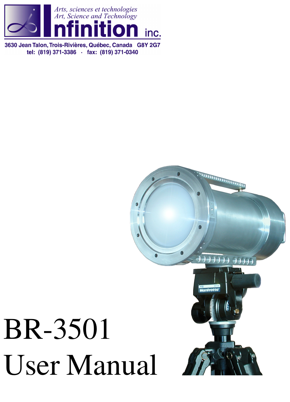
Infinition BR-3501 BR-3501 35 GHz Doppler Radar User Manual UserManual
Infinition Inc BR-3501 35 GHz Doppler Radar UserManual
UserManual.wiki
>
Infinition
>
BR-3501 User Manual
>
rEVISED USER MANUAL
Contents
1.
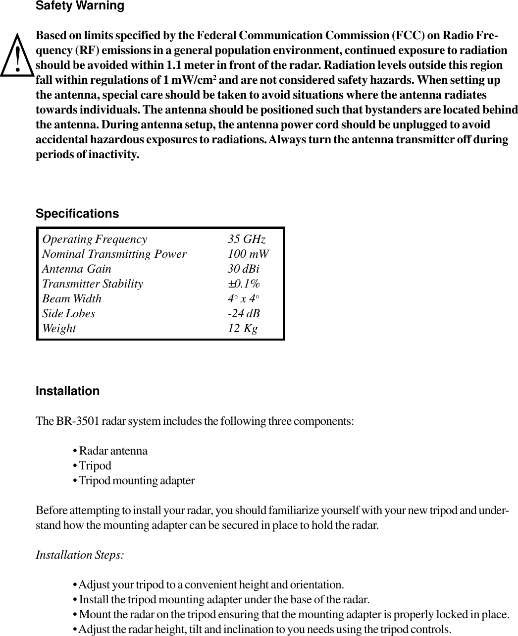
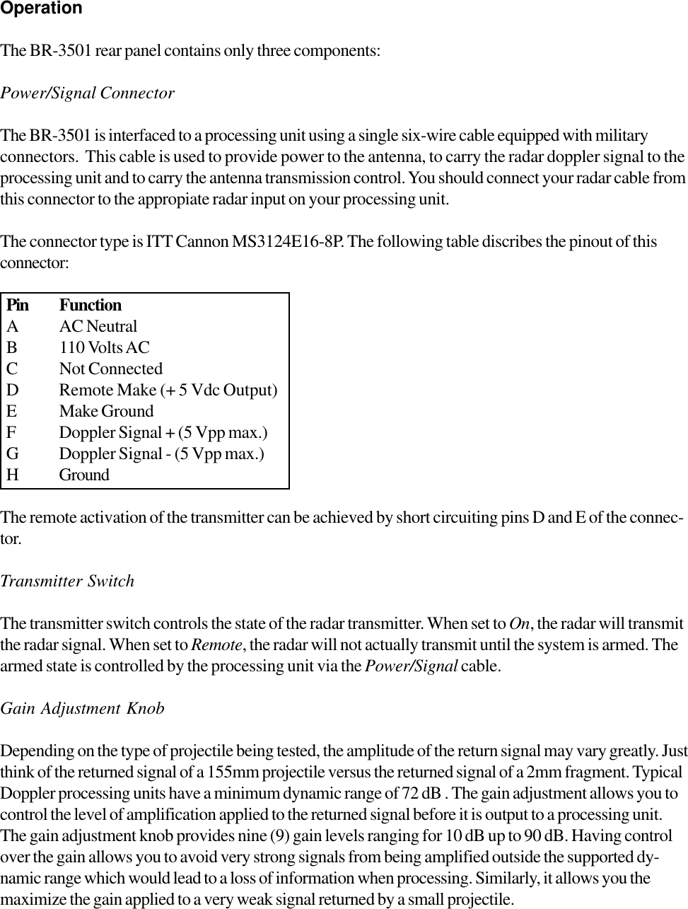
User manual
2.
rEVISED USER MANUAL
rEVISED USER MANUAL
Navigation menu
Upload a User Manual
Namespaces
Wiki Guide
HTML
PDF
Info
Views
User Manual
Discussion / Help
Navigation