Infinition BR-3501 BR-3501 35 GHz Doppler Radar User Manual UserManual
Infinition Inc BR-3501 35 GHz Doppler Radar UserManual
Contents
- 1. User manual
- 2. rEVISED USER MANUAL
rEVISED USER MANUAL
BR-3501
User Manual
Safety Warning
Based on limits specified by the Federal Communication Commission (FCC) on Radio Fre-
quency (RF) emissions in a general population environment, continued exposure to radiation
should be avoided within 1.1 meter in front of the radar. Radiation levels outside this region
fall within regulations of 1 mW/cm2 and are not considered safety hazards. When setting up
the antenna, special care should be taken to avoid situations where the antenna radiates
towards individuals. The antenna should be positioned such that bystanders are located behind
the antenna. During antenna setup, the antenna power cord should be unplugged to avoid
accidental hazardous exposures to radiations. Always turn the antenna transmitter off during
periods of inactivity.
Specifications
Installation
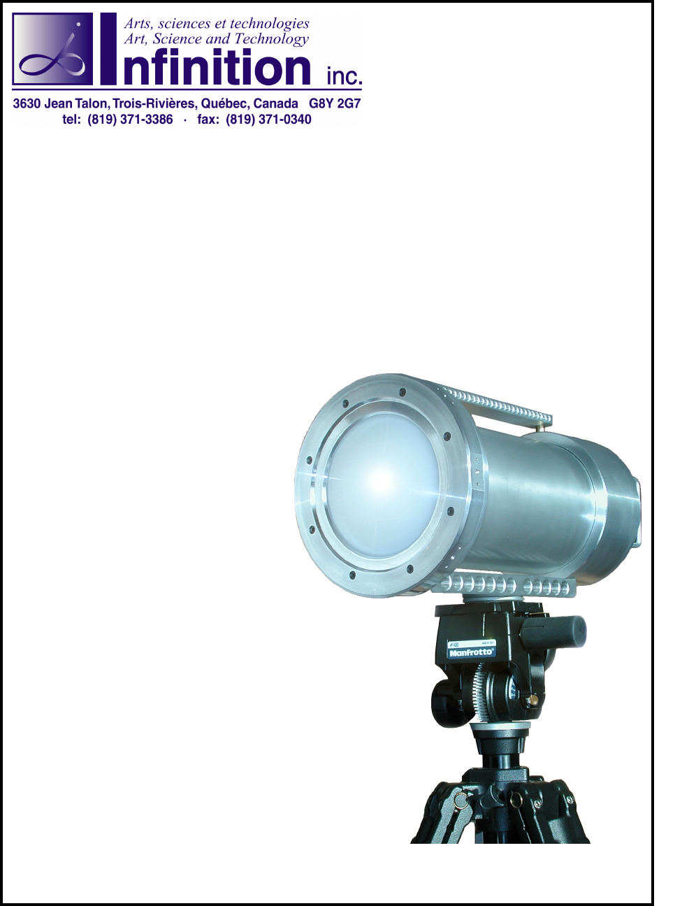
The BR-3501 radar system includes the following three components:
• Radar antenna
• Tripod
• Tripod mounting adapter
Before attempting to install your radar, you should familiarize yourself with your new tripod and under-
stand how the mounting adapter can be secured in place to hold the radar.
Installation Steps:
• Adjust your tripod to a convenient height and orientation.
• Install the tripod mounting adapter under the base of the radar.
• Mount the radar on the tripod ensuring that the mounting adapter is properly locked in place.
• Adjust the radar height, tilt and inclination to you needs using the tripod controls.
Operating Frequency 35 GHz
Nominal Transmitting Power 100 mW
Antenna Gain 30 dBi
Transmitter Stability ±0.1%
Beam Width 4° x 4°
Side Lobes -24 dB
Weight 12 Kg
!

Operation
The BR-3501 rear panel contains only three components:
Power/Signal Connector
The BR-3501 is interfaced to a processing unit using a single six-wire cable equipped with military
connectors. This cable is used to provide power to the antenna, to carry the radar doppler signal to the
processing unit and to carry the antenna transmission control. You should connect your radar cable from
this connector to the appropiate radar input on your processing unit.
The connector type is ITT Cannon MS3124E16-8P. The following table discribes the pinout of this
connector:
The remote activation of the transmitter can be achieved by short circuiting pins D and E of the connec-
tor.
Transmitter Switch
The transmitter switch controls the state of the radar transmitter. When set to On, the radar will transmit
the radar signal. When set to Remote, the radar will not actually transmit until the system is armed. The
armed state is controlled by the processing unit via the Power/Signal cable.
Gain Adjustment Knob
Depending on the type of projectile being tested, the amplitude of the return signal may vary greatly. Just
think of the returned signal of a 155mm projectile versus the returned signal of a 2mm fragment. Typical
Doppler processing units have a minimum dynamic range of 72 dB . The gain adjustment allows you to
control the level of amplification applied to the returned signal before it is output to a processing unit.
The gain adjustment knob provides nine (9) gain levels ranging for 10 dB up to 90 dB. Having control
over the gain allows you to avoid very strong signals from being amplified outside the supported dy-
namic range which would lead to a loss of information when processing. Similarly, it allows you the
maximize the gain applied to a very weak signal returned by a small projectile.
Pin Function
A AC Neutral
B 110 Volts AC
C Not Connected
D Remote Make (+ 5 Vdc Output)
E Make Ground
F Doppler Signal + (5 Vpp max.)
G Doppler Signal - (5 Vpp max.)
H Ground