Ingenico IPA280 POS terminal User Manual manual
INGENICO POS terminal manual
UserManual.wiki
>
Ingenico
>
IPA280 User Manual
>
manual
Contents
1.
user manual
2.
manual
manual
Navigation menu
Upload a User Manual
Namespaces
Wiki Guide
HTML
PDF
Info
Views
User Manual
Discussion / Help
Navigation
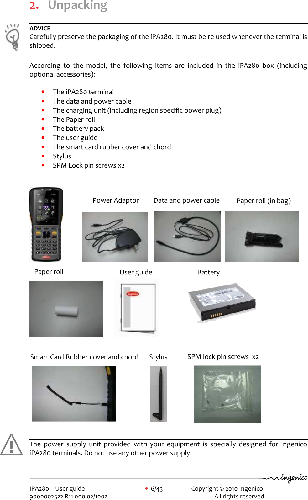
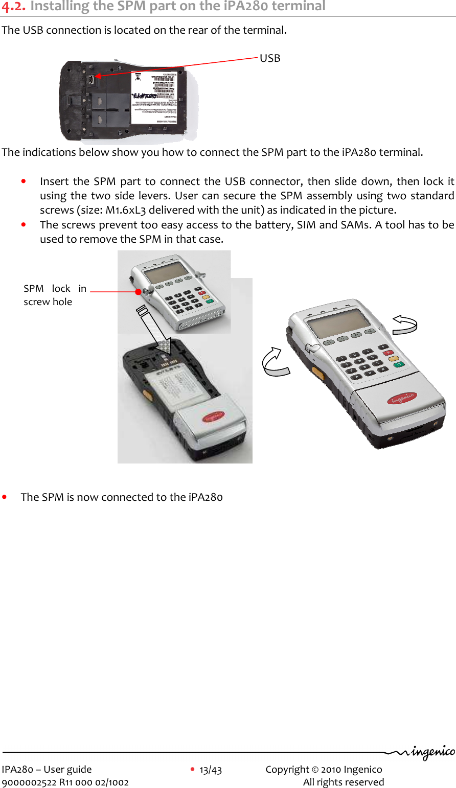
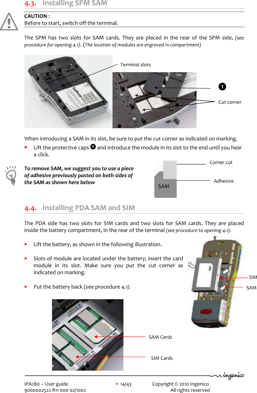
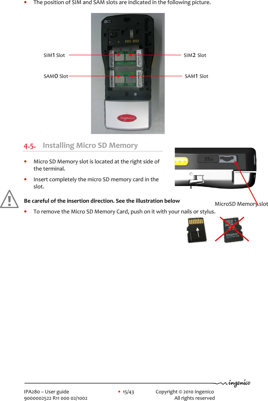
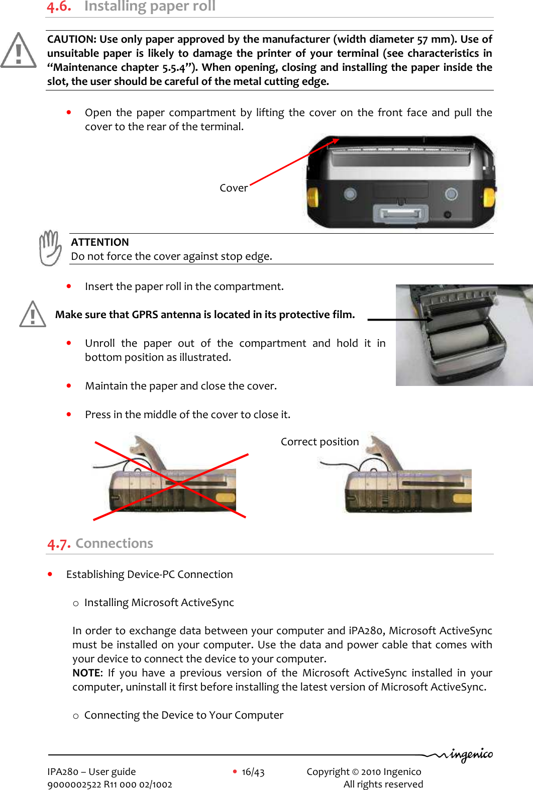
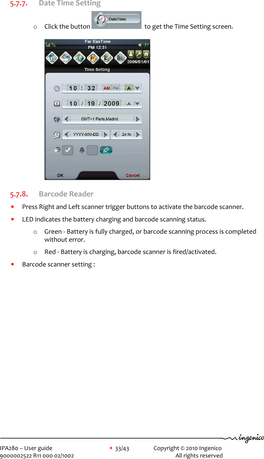
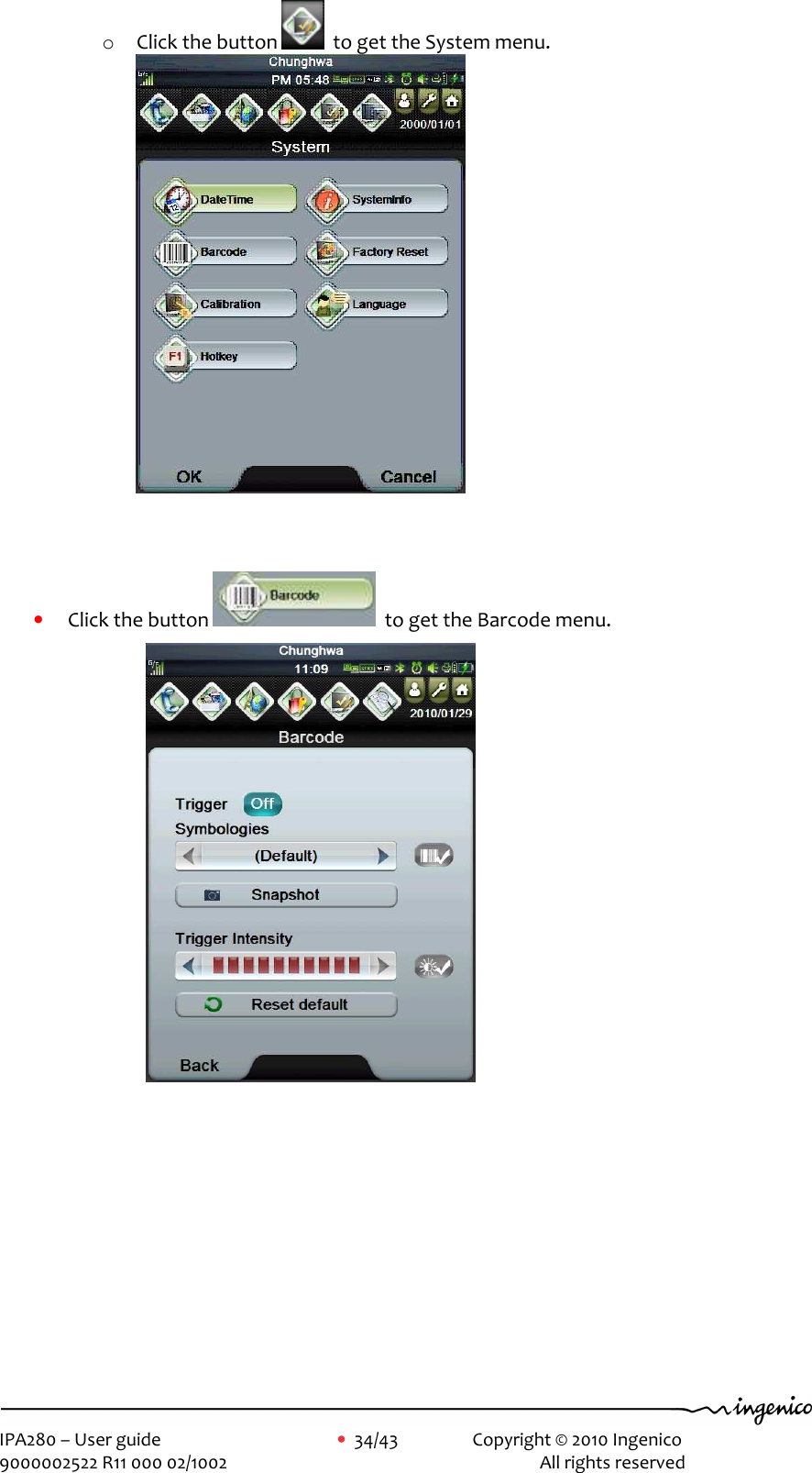
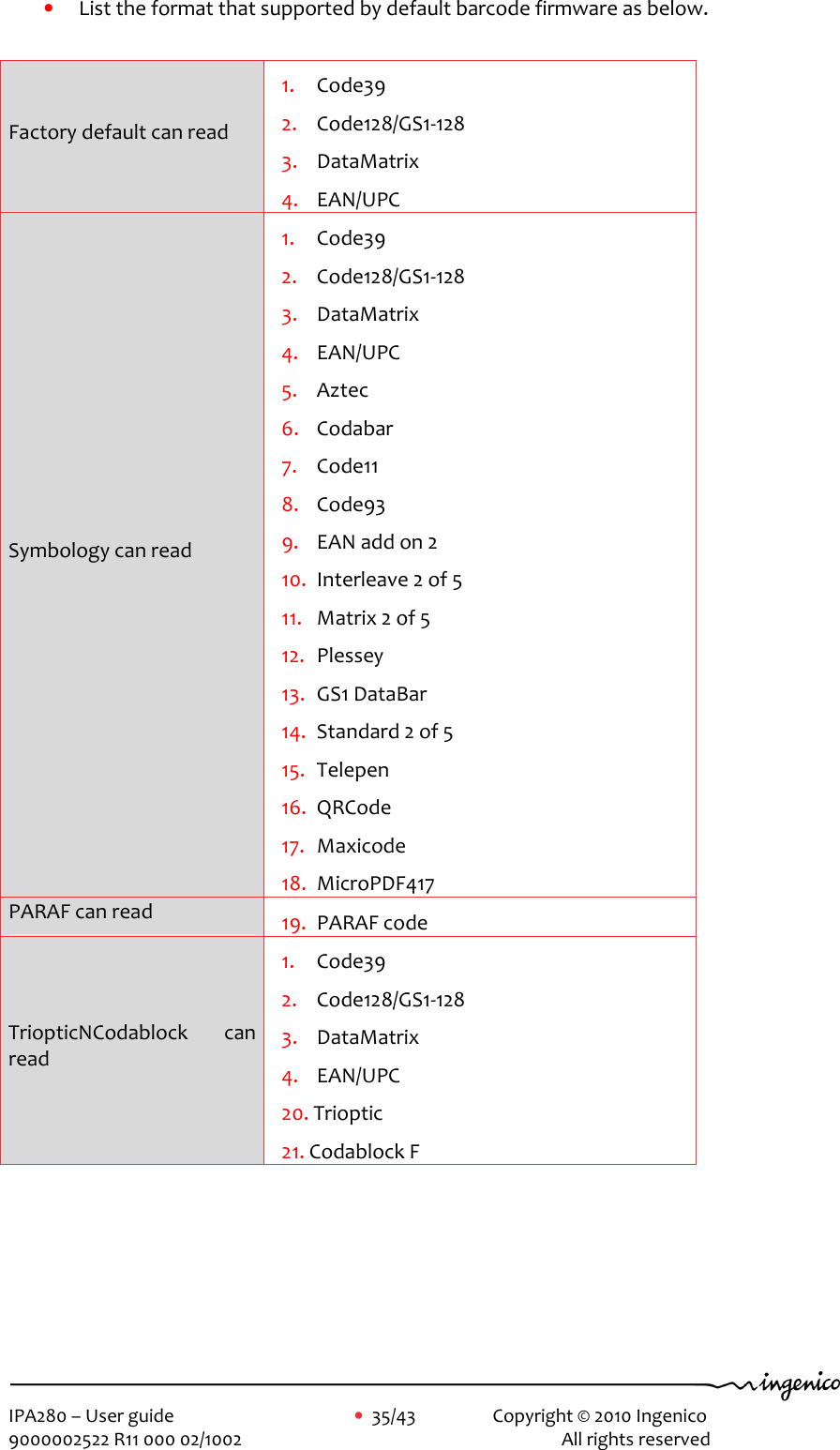
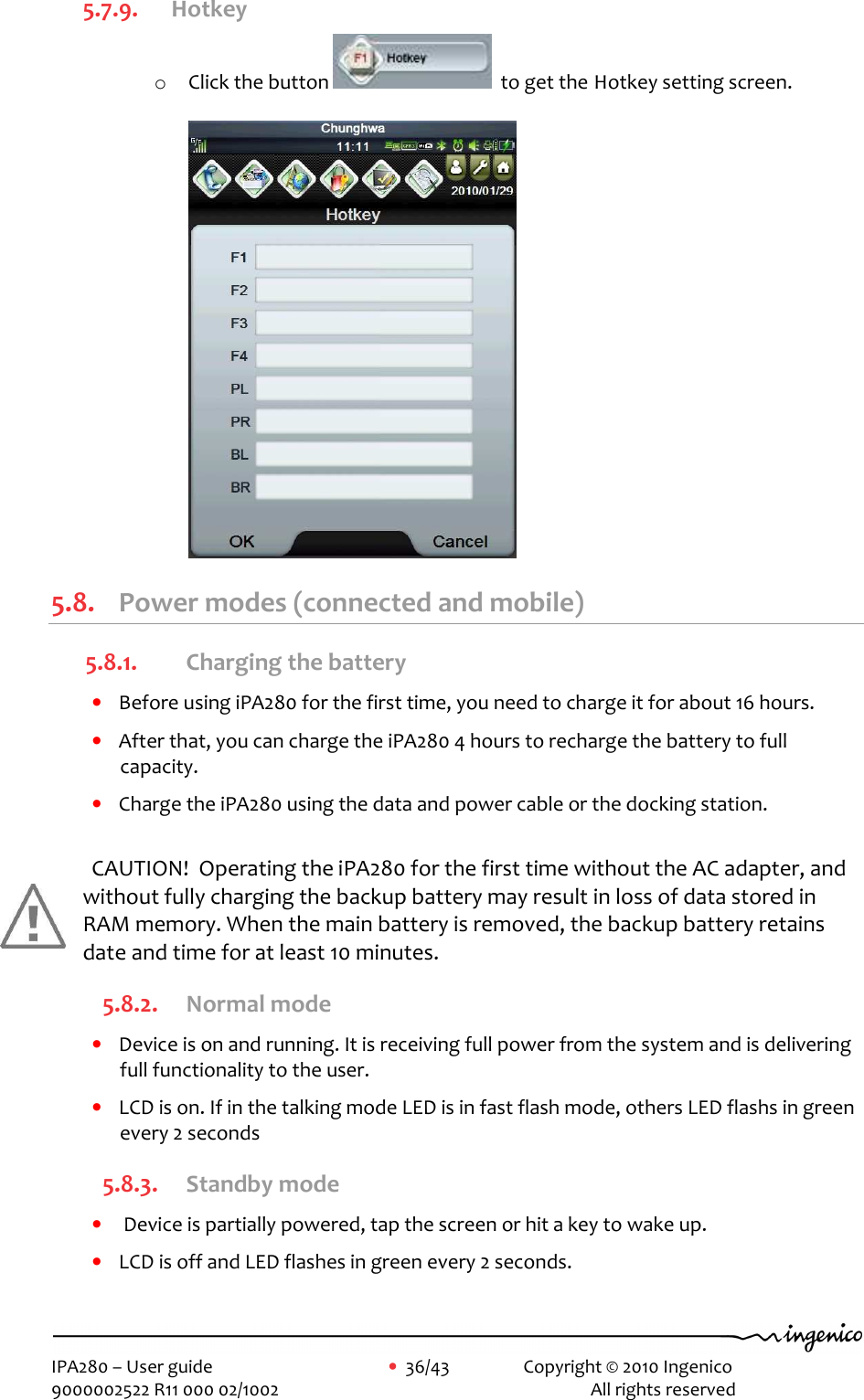
![IPA280 – User guide • 8/43 Copyright © 2010 Ingenico 9000002522 R11 000 02/1002 All rights reserved 3.4. FCC & IC compliance FCC & IC has a specific naming. The references uses for FCC & IC certifications are: • IC: 2586D-IPA280 • FCC ID: XKBIPA280 3.4.1. FCC Statement Federal Communications Commission (FCC) Statement 15.21 You are cautioned that changes or modifications not expressly approved by the part responsible for compliance could void the user’s authority to operate the equipment. 15.105(b) This equipment has been tested and found to comply with the limits for a Class B digital device, pursuant to part 15 of the FCC rules. These limits are designed to provide reasonable protection against harmful interference in a residential installation. This equipment generates, uses and can radiate radio frequency energy and, if not installed and used in accordance with the instructions, may cause harmful interference to radio communications. However, there is no guarantee that interference will not occur in a particular installation. If this equipment does cause harmful interference to radio or television reception, which can be determined by turning the equipment off and on, the user is encouraged to try to correct the interference by one or more of the following measures: -Reorient or relocate the receiving antenna. -Increase the separation between the equipment and receiver. -Connect the equipment into an outlet on a circuit different from that to which the receiver is connected. -Consult the dealer or an experienced radio/TV technician for help. This device complies with Part 15 of the FCC Rules. Operation is subject to the following two conditions: 1) This device may not cause harmful interference and 2) This device must accept any interference received, including interference that may cause undesired operation of the device. 3.4.2. RF Radiation Exposure Statement For body worn operation, this device has been tested and meets RF exposure guidelines when used with an accessory that contains no metal and that positions the device a minimum of 1.5 cm from the body. Use of other accessories may not ensure compliance with RF exposure guidelines. Annex Suggested text for the notice indicating compliance with this standard: This Class [B] digital apparatus complies with Canadian ICES-003.](https://usermanual.wiki/Ingenico/IPA280.manual/User-Guide-1382579-Page-8.png)