Ingenico IUI12X-RF Low Power Equipment User Manual Product Literature

INGENICO Low Power Equipment Product Literature

Contents

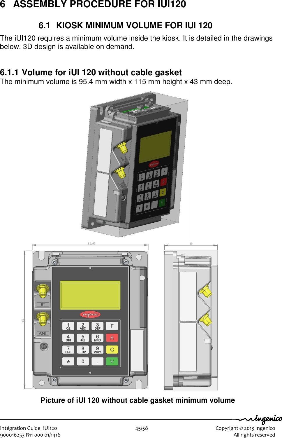
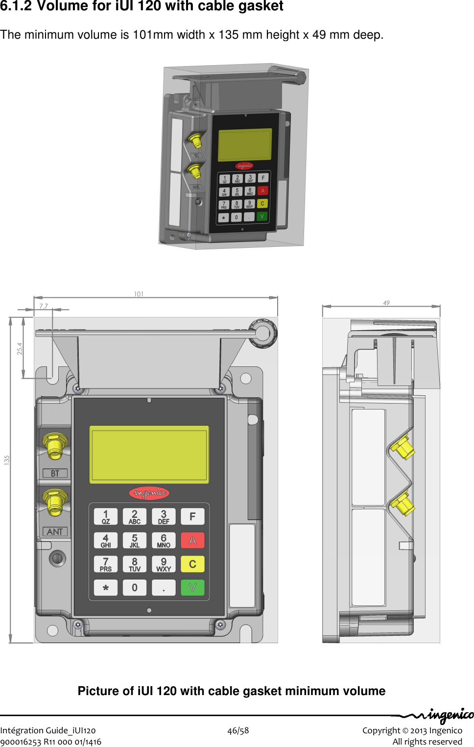
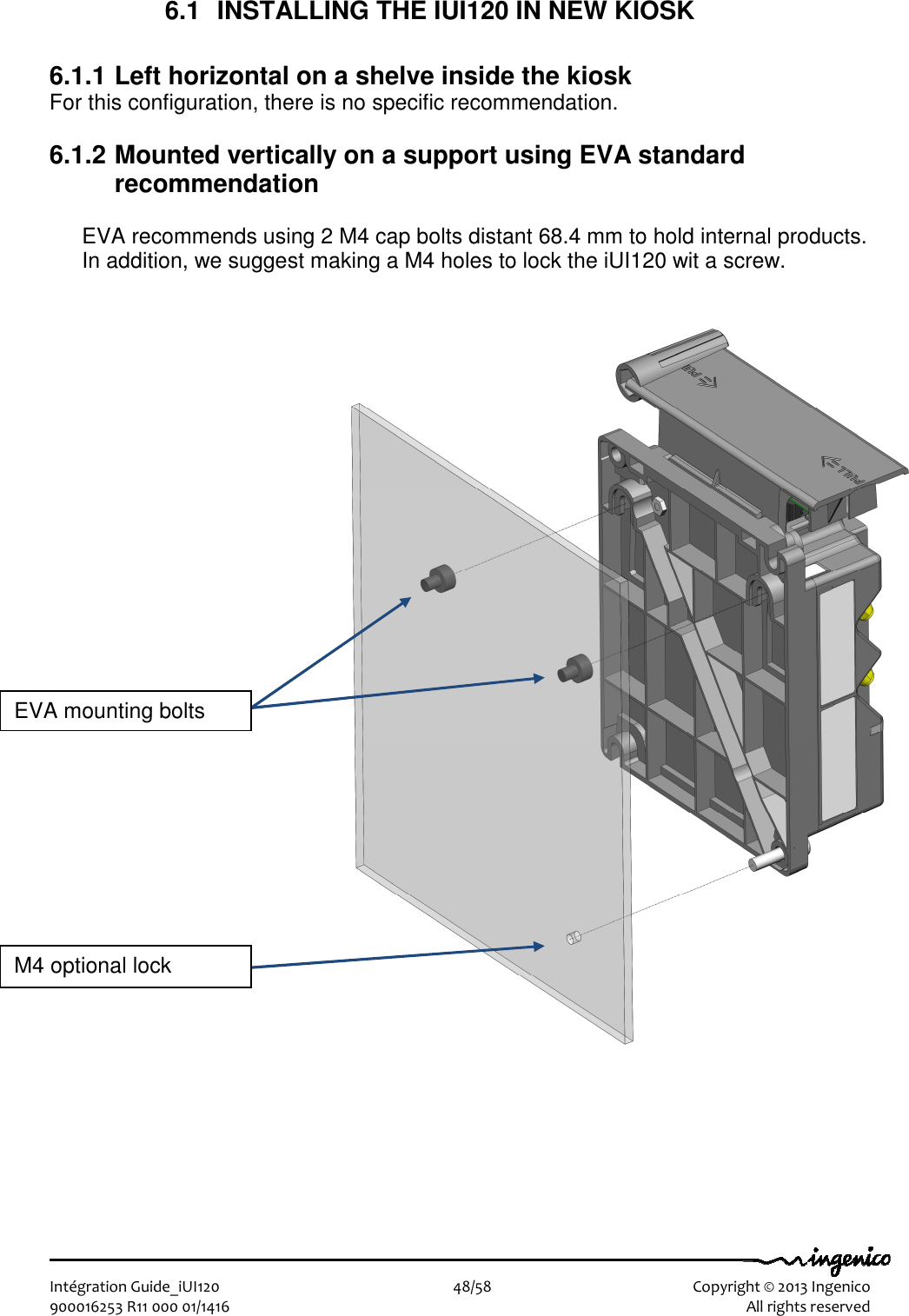
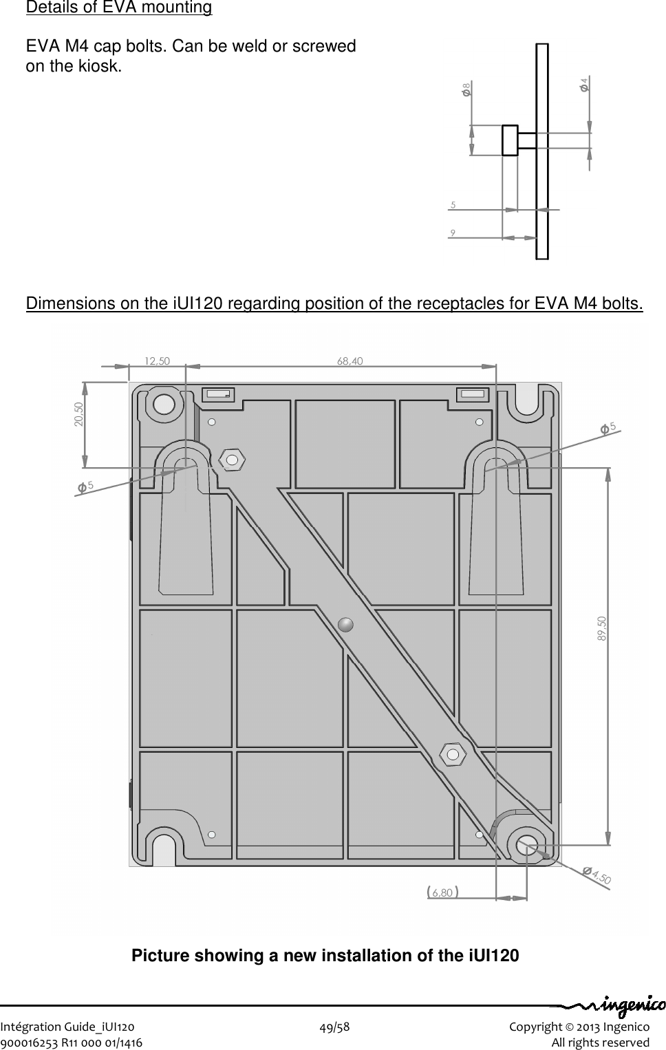
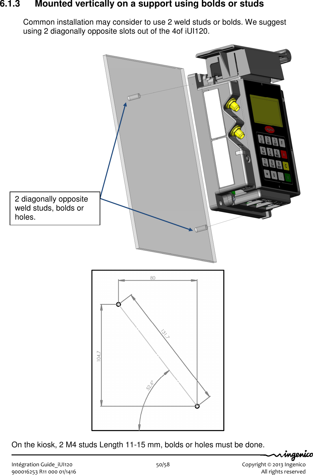
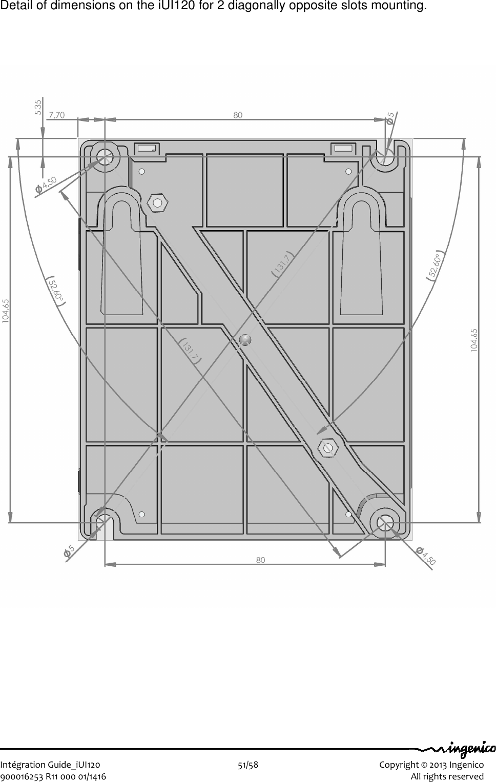
Product Literature.pdf

  Ingenico – 28-32 Boulevard de Grenelle - 75015 PARIS Tél. 33(0)1 58 01 80 00 - Fax 33 (0)1 58 01 91 35           Ingenico Unattended Product iUI120       I n t é g r a t i o n   G u i d e
  Intégration Guide_iUI120                        2/58    Copyright © 2013 Ingenico 900016253 R11 000 01/1416    All rights reserved  The scope of this document is to assist third party integrators when dealing with iUI120 Ingenico Unattended product. It offers all information needed for a successful integration of iUI120 product into unattended kiosk machines.  For any sales information please refer to your Ingenico contact into the region.  Updates table Version  Date  Nature of modifications  Author  Visa 0.1  06/02/2014  First Draft  R Allirot E.Dubois   0.1  15/04/14  Update IC and FCC number  O.Fabregoule
  Intégration Guide_iUI120                        3/58    Copyright © 2013 Ingenico 900016253 R11 000 01/1416    All rights reserved Table of contents 1 GENERAL ............................................................................................................. 6 1.1 Definition of acronyms ..................................................................................... 6 1.2 iUI120 payment solution presentation ............................................................ 7 1.2.1 Diagram of iUI120 connectivity and communications .............................................. 8 1.2.2 Services ................................................................................................................. 9 1.3 Description of iUI120 product ........................................................................ 10 1.3.1 iUI120 product views ............................................................................................ 10 1.3.2 iUI120 Technical Hardware characteristics ........................................................... 11 1.3.3 iUI120 output connectors description .................................................................... 13 1.3.3.1 Ethernet ................................................................................................ 15 1.3.3.2 USB device ........................................................................................... 15 1.3.3.3 USB host ............................................................................................... 15 1.3.3.4 COM0 link ............................................................................................. 15 1.3.3.5 COM2 link (optional) ............................................................................. 15 1.3.3.6 MDB Slave ............................................................................................ 16 1.3.3.7 MDB master (optional) .......................................................................... 16 1.3.3.8 Wake-Up Jack ...................................................................................... 17 1.3.3.9 Bluetooth (optional) ............................................................................... 17 1.3.3.10 GPRS (optional) .................................................................................. 18 1.3.3.11 SAM & µSD Installation ....................................................................... 19 1.3.3.12 Buzzer ................................................................................................. 20 1.3.3.13 Display ................................................................................................ 20 1.3.3.14 Maintenance Button and LED ............................................................. 20 1.3.3.15 iUI 120 Keypad .................................................................................... 21 1.3.3.16 Cable Protection .................................................................................. 22 1.3.3.17 Antenna Installation ............................................................................. 23 1.4 Professional installation Requirement ......................................................... 24 1.5 Wake-UP function a revoir ............................................................................. 25 1.5.1 Wake-up mechanism iUI120 unit .......................................................................... 25 1.5.2 Recommended circuit implementation .................................................................. 26 1.5.3 Power-On sequence iUI120/iUR250/iUC150 ........................................................ 27 2 MAIN ACCESSORIES ........................................................................................ 28 2.1.1 Generality ............................................................................................................. 28 2.1.2 Optional USB cable .............................................................................................. 28 2.1.3 Serial cable .......................................................................................................... 28 2.1.4 LLT cable ............................................................................................................. 29 2.1.5 Stand-by management cables .............................................................................. 30 2.1.5.1 Jack connector ...................................................................................... 30 2.1.5.2 COM0 and COM2 ................................................................................. 30 3 IUI120 SOFTWARE ............................................................................................. 31
  Intégration Guide_iUI120                        4/58    Copyright © 2013 Ingenico 900016253 R11 000 01/1416    All rights reserved 3.1.1 Software Architecture ........................................................................................... 32 3.1.2 Secure management of software .......................................................................... 33 3.1.3 Operating system ................................................................................................. 34 3.1.4 TELIUM MANAGER ............................................................................................. 35 3.1.5 Software downloading .......................................................................................... 37 3.1.6 Development station ............................................................................................. 40 4 TERMINAL MANAGEMENT SYSTEM ............................................................... 42 4.1 Introduction ..................................................................................................... 42 4.2 Basic functions ............................................................................................... 42 4.3 Advanced functions ....................................................................................... 42 4.4 Customers savings with Ingenico TMS solution ......................................... 42 5 INSTALLATION PROCEDURE IN KIOSKS ....................................................... 43 5.1 Security requirement iUI120 .......................................................................... 43 5.2 Kiosk mechanical requirements ............................... Erreur ! Signet non défini. 5.3 General installation recommendations ......................................................... 44 6 ASSEMBLY PROCEDURE FOR IUI120 ............................................................. 45 6.1 Kiosk minimum volume for iUI 120 ............................................................... 45 6.1.1 Volume for iUI 120 without cable gasket ............................................................... 45 6.1.2 Volume for iUI 120 with cable gasket .................................................................... 46 Kiosk preparation for iUI120 new installation ....................................................... 47 6.1 Installing the iUI120 in new kiosk .................................................................. 48 6.1.1 Left horizontal on a shelve inside the kiosk ........................................................... 48 6.1.2 Mounted vertically on a support using EVA standard recommendation ................ 48 6.1.3 Mounted vertically on a support using bolds or studs............................................ 50 7 MAINTENANCE .................................................................................................. 52 7.1 Configuration .................................................................................................. 52 7.2 Operating life ................................................................................................... 52 8 CLEANING INSTRUCTIONS .............................................................................. 52 9 DISASSEMBLING THE PRODUCTS ACCORDING TO WEEE DIRECTIVE ..... 53 9.1 iUC120 End-of–life disassembly instructions .............................................. 53 9.1.1 MODELS AND DESCRIPTIONS .......................................................................... 53 9.1.2 COMPONENTS AND MATERIALS REQUIRING SELECTIVE TREATMENT ...... 53
  Intégration Guide_iUI120                        5/58    Copyright © 2013 Ingenico 900016253 R11 000 01/1416    All rights reserved 9.1.3 PRODUCT DISASSEMBLY PROCESS ............................................................... 54 10 STANDARDS ................................................................................................... 55 10.1 Electrical consumptions ............................................................................. 55 10.2 Temperature and humidity .......................................................................... 55 10.3 Environmental specification continued ..................................................... 55 10.4 EC standard compliance marking .............................................................. 56 10.5 IC statements ............................................................................................... 56 10.6 FCC Statement ............................................................................................. 57 10.7 Environment (WEEE, Batteries and Packaging) ....................................... 58
  Intégration Guide_iUI120                        6/58    Copyright © 2013 Ingenico 900016253 R11 000 01/1416    All rights reserved 1  GENERAL 1.1  DEFINITION OF ACRONYMS  EMC  Electro Magnetic Compatibility EVA  European Vending Association GND  Ground GPRS General Packet Radio Service GSM  Global System for Mobile communications LCD  Liquid Crystal Display LLT  Local Loading Tool MDB  Multi Drop Bus RAM  Random Access Memory RS232 Recommended Standard 232. A standard for serial binary communications SAM  Secure Access Module – the chips storing the electronic cash register in a stored value scheme such as Moneo, Proton or VISA Cash. SMA  SubMiniature version A USB  Universal Serial Bus
  Intégration Guide_iUI120                        7/58    Copyright © 2013 Ingenico 900016253 R11 000 01/1416    All rights reserved  1.2  IUI120 PAYMENT SOLUTION PRESENTATION The iSelf Series is the new range of Ingenico unattended devices to offer payment into any kiosk through any segments (petrol, transport, vending, parking, etc.).  The modules for iSelf Series are: for contactless reading, iUC150,iUC180,iUC180B for contact and magnetic strip reading, iUR250 for PinPad entry , IUP250.  These compact devices are designed to fit everywhere, thanks to an easy installation, respectful of EVA EPS (Standard door module). Usage can be indoor or outdoor, resisting to harsh environment.  Remarks: • For iUC180 & iUC180B, additional peripherals can be added to build a complete solution such as printer or bar code reader. Ingenico does not provide these devices so far but they can be connected to the iUC180 & iUC180B (through USB, or RS232). • Ingenico is also offering other iSelf Series modules dedicated to PINPad like iUP250 or Hybrid Card Reader iUR250. • The iUC150 is the preferred contactless peripheral for the iUP250+iUR250 solution.  The iSelf Series is the next generation of Ingenico leveraging of experience from previous product ranges, i9500 series or CAD30 series, to renew your experience of unattended payment.
  Intégration Guide_iUI120                        8/58    Copyright © 2013 Ingenico 900016253 R11 000 01/1416    All rights reserved 1.2.1 Diagram of iUI120 connectivity and communications                  Serial port com0  display  Power supply Main Power supply Ethernet  4 USB host GSM / GPRS MDB master Serial port com2 (Option)  (Option)  (Option)  (Option)  Bluetooth 1USB device 10 – 45 V Max 2A MDB slave Keypad iUI120
  Intégration Guide_iUI120                        9/58    Copyright © 2013 Ingenico 900016253 R11 000 01/1416    All rights reserved 1.2.2 Services   Training − Unattended − Installation and exploitation  − Softwares  − OEMC/M²OS development ( days) − EMV Level 2 package (2 days) − Development workstation SDK Support − Hot-line support − Technical assistance After-Sales Service − Fixed cost repair of iSelf Series products Downloading server centre − User licence − Installation and commissioning − User training  − Hot-line support − Technical assistance Softwares / Licences − User licence for local loading tool, LLT − User licence for applications software  − User licence for M²OS − Licence for software signature tool, SAT − Licence for "EMV Level 2 package " − Licence for TCP/IP − …
  Intégration Guide_iUI120                        10/58    Copyright © 2013 Ingenico 900016253 R11 000 01/1416    All rights reserved 1.3  DESCRIPTION OF IUI120 PRODUCT  1.3.1 iUI120 product views                                               Front view  Rear view
  Intégration Guide_iUI120                        11/58    Copyright © 2013 Ingenico 900016253 R11 000 01/1416    All rights reserved  1.3.2 iUI120 Technical Hardware characteristics   Mass  247 g Dimensions  134 x 106 x 48 mm (height x width x depth) Power Supply   iUI120 : 10 – 45 V Max   2A Platform Telium2  Memory  16 Mb SDRAM and 128 Mb Flash Functionality Buzzer RGB led internal status indicator 1 Maintenance Button µSD  2 SAM 1 SIM (optional) 1 Jack for wake-up wake-up mechanism on RS232 connectors Keys: 16 keys for maintenance 128 x 64 graphic display maintenance Link Ethernet GSM/GPRS (optional) Bluetooth (optional) 4 USB host (1.2 A total max) 1 USB device 2x RS232 (1 optional) MDB slave MDB Master (optional)  GPRS detailed characteristics The GPRS connection is optional in iUI120  Characteristics  GSM/ GPRS Frequency  Quad band:  GSM (850, 900Mhz)  DCS (1800Mhz)  PCS (1900Mhz)
  Intégration Guide_iUI120                        12/58    Copyright © 2013 Ingenico 900016253 R11 000 01/1416    All rights reserved Transit power   Class 4 (2W) for GSM850 / EGSM900 Class 1 (1W) for DCS1800 / PCS1900 Communication feature  Multi slot Class 10 ( 4+1, 3+2) Stay connect feature GPRS baudrates  Downlink up to 85.6 kbps,  Uplink up to 42.8 kbps  Bluetooth detailed characteristics  Characteristic  Bluetooth V2.0 Chipset   Bluecore 6  Standard compliance  Bluetooth v2.1 EDR (enhanced data rate) – Class 2 Profile  SPP Other profile to be analysed on request  Radio transfer rate  1 Mbit/s 2Mbit/s (EDR)  Number of supported links  7 slaves to 1 base Range  Indoor: 10m typical  Bluetooth Class 2 – mini 10m in free sight  Operating conditions  Functional temperature*  -20°C, +65°C Max relative humidity  85% at 55°C, non-condensing
  Intégration Guide_iUI120                        13/58    Copyright © 2013 Ingenico 900016253 R11 000 01/1416    All rights reserved 1.3.3 iUI120 output connectors description                   Top view                         Right view      COM 0  MDB Slave  MDB Master SIM  2 SAMs  µSD  COM2 Link  Wake-Up Link
  Intégration Guide_iUI120                        14/58    Copyright © 2013 Ingenico 900016253 R11 000 01/1416    All rights reserved                    Bottom view                        Left view       Ethernet USB Device USB Hosts Bluetooth Antenna GPRS Antenna LLT/Maintenance LED  LLT/Maintenance Button
  Intégration Guide_iUI120                        15/58    Copyright © 2013 Ingenico 900016253 R11 000 01/1416    All rights reserved 1.3.3.1  Ethernet   The iUI120 unit can be connected to Ethernet. The connector type is shielded RJ45. The Ethernet cable is standard and not provided. The Ethernet cable must be shielded.  1.3.3.2  USB device  The iUI120 unit can be connected by type B USB.  1.3.3.3  USB host  The iUI120 unit can drive 4 USB accessories. The connector is standard type A. The power available is limited to 1.2A Max dispatched between the 4 USB.    1.3.3.4  COM0 link  The iUI120 unit can be connected to serial port COM0.  The connector type is RJ11.  Pin N°  Function 1  GND 2  Wake-up 3  RXD 4  TXD 5  CTS 6  RTS   1.3.3.5  COM2 link (optional)  The iUI120 unit can be connected to serial port COM2 if the option is available.  The connector type is RJ11.   Pin N°  Function 1  GND 2  Wake-up 3  RXD 4  TXD 5  CTS 6  RTS
  Intégration Guide_iUI120                        16/58    Copyright © 2013 Ingenico 900016253 R11 000 01/1416    All rights reserved 1.3.3.6  MDB Slave  iUI120 unit can be connected by MDB slave. The connector type is MDB 6 pins (Mini – Fit series 87827 (MOLEX)). iUI120 unit is powered on the MDB connectors by power supply 10 to 45V DC (45V is a maximum).               A Würth ferrite ref 74270077 or equivalent must be added on the power cable.      1.3.3.7  MDB master (optional)  The iUI120 unit is powered on the MDB connectors by power supply 10 to 45V DC (45V is a maximum). See below iUI120 unit can be connected by MDB master if option available. The connector type is MDB master 8 pins (Mini – Fit series 87827 (MOLEX)). iUI120  unit  does  not  support  EXE  power  supply.  Specific  accessory  are available. A Würth ferrite ref 74271222 or equivalent must be added with two turns on the cable.                 Pin N°  Function 1  Vin 2  GND 3  NC 4  MDBS_RXD 5  MDBS_TXD 6  MDBS_COMMUN Pin N°  Function 1  NC 2  NC 3  NC 4  NC 5  MDBM_RXD 6  ISO_GND 7  MDBM_TXD 8  ISO_GND
  Intégration Guide_iUI120                        17/58    Copyright © 2013 Ingenico 900016253 R11 000 01/1416    All rights reserved   1.3.3.8  Wake-Up Jack  This connector is used for Wake-up mechanism.  Pin N°  Function 1  GND 2  HZ  Stand-by authorized “0”  Wake-up / Stand-by unauthorized   WARNING : The specific jack and cable is a spare part, contact commercial service to purchase it. Warning: do not plug-in a DC power in the jack. It could damage the iUI120.                       1.3.3.9  Bluetooth (optional)  When the iUI120 unit is ordered with Bluetooth option, it must be connected to an external Bluetooth antenna.  Ingenico can provide an antenna, or a standard one can be used. This standard Antenna must have an impedance of 50 Ohm and a maximum gain of 0 dBi.  Ingenico recommended antennas:   Antenna type  manufacturer  model  gain  impedance  Minimum cable length Ingenico  Reference
  Intégration Guide_iUI120                        18/58    Copyright © 2013 Ingenico 900016253 R11 000 01/1416    All rights reserved bipolar  EAD  FBTS35024-SM-ST  0dBi  50ohm  0  192023282   1.3.3.10  GPRS (optional)  When iUI120 product is provided  with GPRS functionality (configuration upon request), the external antenna is not provided with the unit.   Ingenico can provide an antenna, or a standard one can be used. This standard Antenna must have an impedance of 50 Ohm and a maximum gain of 3.5 dBi.   The SIM used for GSM functionality must be assigned to SIM slot.   Ingenico recommended antennas:   Antenna type  manufacturer  model  gain  impedance  Minimum cable length Ingenico  Reference  bipolar  AMPHENOL  90-00234  1.7dBi  50ohm  0  179900131 bipolar  HIRSHMANN  MCA 18 90 MP  2.1dBi  50ohm  2.5m  189968573 bipolar  Giga concept  GC300M-011-2500  2.2dBi  50ohm  2.5m  189963487
  Intégration Guide_iUI120                        19/58    Copyright © 2013 Ingenico 900016253 R11 000 01/1416    All rights reserved 1.3.3.11  SAM & µSD Installation  1.  Disconnect the iUI120 unit from the main power supply. 2.  Open the SAM door by removing the screw. 3.  Insert the SAM cards in SAM slot 1 and /or slot 2  4.  Insert µSD card in µSD slot 5.  Insert SIM card in SIM slot.  6.  Slide the SAM door and screw.                                            SAM cover Screwed with M2X6 T6 SIM Slot SAM1 Slot µSD Slot SAM2 Slot 2
  Intégration Guide_iUI120                        20/58    Copyright © 2013 Ingenico 900016253 R11 000 01/1416    All rights reserved                            For SAM/SIM cards, take care of cards orientation and do not push in excess the cards.  After insertion, the cards position is 4 mm out of the products as shown on picture.   1.3.3.12  Buzzer  The buzzer is controlled by application. The frequency depends of software.     1.3.3.13  Display  The iUI120 have a black and white display.    1.3.3.14  Maintenance Button and LED  The iUI120 unit has a maintenance button at the back.  -  To enter LLT mode, press the button at power up or at restart, until the red LED lights on. -  To enter Maintenance mode, press the button at power up or at restart, until the red LED starts blinking. -  To restart the product, press the button until the blue LED lights on. Cut angle for SAM Cut shape for µSD card Cut angle for GPRS SIM angle For
  Intégration Guide_iUI120                        21/58    Copyright © 2013 Ingenico 900016253 R11 000 01/1416    All rights reserved 1.3.3.15  iUI 120 Keypad     Remarks: The rear display and the keyboard can only be used in maintenance mode. “*” and “.” are used for Up and Down.
  Intégration Guide_iUI120                        22/58    Copyright © 2013 Ingenico 900016253 R11 000 01/1416    All rights reserved 1.3.3.16  Cable Protection   A cable sealing sleeve is provided with iUI120 unit to protect the top of product against water runoff.  Connect the cables, and snap in the part on the rear cover to cover the cables.  This sleeve also holds the antenna tool for GPRS and BT options.  Proposed position for cables:              Cable sealing sleeve clipped on back cover
  Intégration Guide_iUI120                        23/58    Copyright © 2013 Ingenico 900016253 R11 000 01/1416    All rights reserved 1.3.3.17  Antenna Installation  A tool is provided to help screwing the external antenna. 1.  Remove the antenna tool from the cable sleeve. 2.  Insert the SMA antenna cable through the slot of the antenna tool. 3.  Slide the antenna tool over the SMA Cable connector. 4.  Screw the cable.          Antenna tool rest position
  Intégration Guide_iUI120                        24/58    Copyright © 2013 Ingenico 900016253 R11 000 01/1416    All rights reserved 1.4  PROFESSIONAL INSTALLATION REQUIREMENT   Ingenico only sells its products, to qualified partners and integrators. They are in charge of professionally resell, integrate, and install these products inside complete solution for end customers. These end customers solution can be: •  Petrol station. •  Ticketing kiosk (Airline tickets, cinema, transport, etc.) •  Vending machine operator •  Parking kiosk (On / off street) •  Other Thus, the general public cannot purchase Ingenico hardware or software. Partners, resellers, and Integrators must have qualified electronics engineers to be able to install or integrate our products. Furthermore, they must follow a specific technical training conducted by Ingenico technical experts. In addition installation must follow Ingenico recommendations, as describe in this document, in order to respect: •  Local regulations for Electrical Safety and Radio emission levels •  Ferrite beam installation  Our field support & maintenance engineers are available for follow up and commissioning of installation.
  Intégration Guide_iUI120                        25/58    Copyright © 2013 Ingenico 900016253 R11 000 01/1416    All rights reserved 1.5  WAKE-UP FUNCTION A REVOIR  1.5.1 Wake-up mechanism iUI120 unit  iUI120 unit is designed to save power thanks to a “stand-by mode”. If the stand-by mode is used, use Wake-up mechanism: -  with button connected on jack (optional)  -  with Pin 2 of COM0 link & COM2 link -  by pressing the green key on the maintenance keyboard.  Wake-up pin state   Hz (high impedance)  Stand-by authorized Drive to “0”  Wake-up / Stand-by unauthorized  The Wake-up pin is drive to “0” by the one asking the wake-up.  It  could  be  driven  by  iUR250  or  any  devices  designed  to  be  compliant  (Host device…).                       IUI120 COM0 & 2  1 – GND 2 – Wake-up 3 4 5 6 HZ => Stand-by « 0 » => Wake-up  USB Any devices design to be compliant. HZ => Stand-by « 0 » => Wake-up
  Intégration Guide_iUI120                        26/58    Copyright © 2013 Ingenico 900016253 R11 000 01/1416    All rights reserved   1.5.2 Recommended circuit implementation
  Intégration Guide_iUI120                        27/58    Copyright © 2013 Ingenico 900016253 R11 000 01/1416    All rights reserved  1.5.3 Power-On sequence iUI120/iUR250/iUC150 This configuration describes the worst case for wake-up timing.
  Intégration Guide_iUI120                        28/58    Copyright © 2013 Ingenico 900016253 R11 000 01/1416    All rights reserved   2  MAIN ACCESSORIES 2.1.1 Generality  For a complete description of Ingenico Accessories, please refer to iselfseries accessories catalog.  2.1.2 Optional USB cable  An optional USB cable (spare part reference 296129367) with short right-angle overmolded connectors can be purchased as an accessory. This cable is designed to optimize the required volume for iUI120 installation in the kiosk and allows the use of the cable sleeve.    2.1.3 Serial cable
  Intégration Guide_iUI120                        29/58    Copyright © 2013 Ingenico 900016253 R11 000 01/1416    All rights reserved 2.1.4 LLT cable
  Intégration Guide_iUI120                        30/58    Copyright © 2013 Ingenico 900016253 R11 000 01/1416    All rights reserved 2.1.5 Stand-by management cables  2.1.5.1  Jack connector   Definition of the jack connector:    2.1.5.2  COM0 and COM2  Specification available on demand.
  Intégration Guide_iUI120                        31/58    Copyright © 2013 Ingenico 900016253 R11 000 01/1416    All rights reserved 3  IUI120 SOFTWARE  The system unit, equipped with Telium2® technology, is designed with a structure supporting several applications without any mutual interference.   The operating system is a multi-task, real time, preemptive system.  The inputs and outputs are managed by interrupts.  This provides for simultaneous processing of peripherals, thus increasing system unit performance.  It is downloadable to FLASH memory.
  Intégration Guide_iUI120                        32/58    Copyright © 2013 Ingenico 900016253 R11 000 01/1416    All rights reserved 3.1.1 Software Architecture                                           The software architecture is divided into levels:  •  System  •  Multi-application manager •  Universal Controller Module Component (UCMC) •  Independent applications  Telium manager System  Applications  Resident loading Bootstrap Power up Operating system Local loading Application manager Downloading Remote diagnostics Local  diagnostics Appli 2 CB Appli Appli 3  Appli n UCMC  UCM component Transaction Flow Management USB slave/ PSU 5V Memory µSD SAM Display  Keypad USB  COM Ethernet GPRS MDB Bluetooth
  Intégration Guide_iUI120                        33/58    Copyright © 2013 Ingenico 900016253 R11 000 01/1416    All rights reserved The system manages access to all the terminal’s peripherals. Access is achieved through standard C primitives for all the input/output peripherals (keypad…) and through specific primitives for the other peripherals (smart cards and magnetic stripe cards). Further, the system takes charge of memory management. It allocates memory space to the software applications and access control.  The multi-application manager is the entity, which calls the various applications downloaded in the terminal in response to the various events that occur in the terminal.  The UCMC component interfaces between the applications and the peripherals (PINPad, Reader, Printer…). This makes the applications independent of the peripherals.  It can also manage the « transaction flow ».  The applications are modelled around the demands made by the multi-application manager. Each request or input point represents a processing operation to be performed. Each application manages the execution of these processing operations according to its specifications. This standardization based on input points simplifies the implementation of the applications on terminals. The terminal provides natural access to the modularity concepts and improves the maintainability and quality of the applications.   3.1.2 Secure management of software  The terminal is designed to execute authentic software only and to do this in a ranked context.  The terminal performs the following checks:  1.  During a software download, the terminal checks :  •  Its authenticity, by checking its signature with the RSA algorithm with a 2048 bit key. 2.  Before running a software, the terminal checks :  •  Its presence by looking for the software’s identity. •  Its integrity by checking checksums and CRCs.
  Intégration Guide_iUI120                        34/58    Copyright © 2013 Ingenico 900016253 R11 000 01/1416    All rights reserved 3.1.3 Operating system  Bootstrap  Bootstrap is resident.  The bootstrap very briefly takes control of the terminal after each power up to perform the initialization and the self-test. Then, it automatically runs the operating system, which in turn starts the applications manager.   Thus, the Bootstrap provides the following functionalities: •  Memory and checksum self-test •  Local download of the operating system if absent •  Operating system authenticity check and start-up.  Operating system characteristics   The operating system is downloaded (locally or remotely) into the memory. It is upgradeable. After a few fractions of a second following a power-up, the operating system takes control. It checks the presence, integrity and authenticity of the system components and application software present in the terminal.  The maintenance sub-system takes control in the following cases: •  if no authentic application is present,  •  or, if a manual action is made by the operator during power up,  •  or, if it is activated by an application.   The maintenance sub-system ensures, among other things, the downloading of the application software.   The operating system ensures the start of the multi-task core and then runs the applications by making a set of services available to them:   •  Multi-task management: Availability of a pre-emptive real-time environment, based on interruptions, events and mailboxes. This management enables simultaneous processing, which improves the terminal’s performance. •  Input/Output management: This is carried out under interruptions, generally in buffered mode. Thus, the application developer enters a “conventional” C context. •  System alarm management: Certain incidents detected by the operating system are recorded. They can be used later by the maintenance sub-system during remote or local diagnostics.  •  Application alarm management: A number of incidents detected by the applications can be saved by the operating system at their request. This recording is used later as in the case of system alarms. •  Application isolation management: The operating system provides the mechanisms described in the section on software isolation and memory protection.  Inter-application isolation is managed by the Memory Management Unit (MMU). •  Application download management: The operating system offers the downloading services described in the « Software download » section.
  Intégration Guide_iUI120                        35/58    Copyright © 2013 Ingenico 900016253 R11 000 01/1416    All rights reserved 3.1.4 TELIUM MANAGER The main functions offered by the manager are the following:  •  Application management •  Terminal initialization •  Terminal maintenance •  Card Recognition and routing to the applications  When the EMV DC module is present, it selects the applications:  •  EMV applications  (EMV level 2 compliant)  •  Non-EMV applications   In France, it is compatible with the following environments  •  Health system  •  French banking system •  "Private applications" Terminal initialization Required operating conditions  To  operate,  the  system  unit  has  to  be  equipped  with  its  system,  the  application manager, the UCMC and at least one application.  If no application is initialized, the application manager displays a message requesting initialization for an application (in maintenance mode). If  at  least  one  application  is  initialized,  the  terminal  is  operational.  The  application manager then waits for an event to poll the applications loaded in the terminal.  Initialisation of common parameters (in maintenance mode) The application manager is used to initialize the common parameters: Date, time, message display language, IP network configuration data, local loading or remote diagnostics.  System unit maintenance (in maintenance mode) The system unit has maintenance functions.  •  Properties •  Local downloading  •  Diagnostics
  Intégration Guide_iUI120                        36/58    Copyright © 2013 Ingenico 900016253 R11 000 01/1416    All rights reserved Properties The properties function is used to obtain the following information: •  List of applications loaded in terminal, version number, checksum, etc. The application manager gives this information for itself and for the operating system.   •  Application call time: remote collection, loading, etc. •  Total number of transactions in each application file contained in system unit.  Download  The downloading function uses the information supplied on initialization of the application manager. The program update function is used to update the system unit by: •  Using a special local loading tool connected to the terminal, •  Using a remote loading tool, •  Using a USB key. The iUI120 must be in maintenance mode with a USB key containing the software to load plugged in. Then, launch the download by using the manager menu  Diagnostics The diagnostics function is used for:  •  Local diagnostics  The operator can request the incidents or alarms stored in the terminal.   The storage function implements two sets of elements: o  Incident counters: Used for « repetitive » incidents, for which only the number of occurrences is significant. For example, number of power on.   o  Events: Exceptional in nature. The information content depends on the type of incident. Generally, this comprises the date, time and information relative to the incident itself. The events are stored in a rotating file where the most recent events are kept.   •  Remote diagnostics  This function is used by the operator to trigger a call to a server to dump the information stored in the terminal. The server thus enriches a database by which it can efficiently monitor a terminal population, or propose services such as preventive maintenance, operating statistics, etc.   •  Diagnostics by USB key Diagnostic files are copied to a USB key if present at start-up. •  Note :  Displaying Bluetooth & GPRS information at the same time is not possible on iUI120. In maintenance mode it’s possible to display one information or the other by pressing “0” key By default, GPRS info is displayed.
  Intégration Guide_iUI120                        37/58    Copyright © 2013 Ingenico 900016253 R11 000 01/1416    All rights reserved 3.1.5 Software downloading Downloading The software can be downloaded:   •  Locally via the serial link (COM or USB).  •  Remotely, via the switched telephone network (PSTN) using an external modem, Ethernet, GPRS, TCP/IP network. •  By a USB key. The iUI120 must be in maintenance mode with a USB key containing the software to load plugged in. Then, launch the download by using the manager menu.  The techniques used:   •  Data compression,  •  Authenticity checking,  •  Memory allocation management, •  TCP/IP,   best optimize the software downloading operations.  These  features  provide  faster  downloading  time,  enhanced  security,  an  ease  in upgrading, and a larger number of software installed on the system unit.  Local Loading Tool (LLT) The LLT is used for local software download.   The LLT is formed by:  •  A  PC running with Windows Seven, Vista Pro, XP, 2003 Server, 2000 Professional SP2  •  A INGENICO loading software,  •  A PC-terminal connecting cable Local loading is performed:  •  From a PC equipped with the Local Loading Tool (LLT) on the COM serial or slave USB link  •  By automatic switching to the local loader of the operating system.  Two connections are possible:   •  By COM link:     Speed 115200 bits/s •  By slave USB link:     Speed 8 Mbits/s approx.  Selection of the software to be loaded is guided on the PC  screen  by an Explorer type Windows system (Windows loader).  Loading time for a 1Mo application is 4s by USB port.
  Intégration Guide_iUI120                        38/58    Copyright © 2013 Ingenico 900016253 R11 000 01/1416    All rights reserved Loading by USB key With the USB key loading method, the software is loaded locally with no need for a PC type tool. The loading time is identical to that of the USB.  Terminal Management Server (TMS) For a complete description of the TMS possibilities, refer to the "TMS" section.  Loading and management of memory space in system unit Before  a  (down)load,  the  system  ensures  that  the  necessary  memory  space  is available. The software (possibly compressed) are downloaded to flash. If software is deleted, the system frees the space. If software is upgraded, the system loads the new software, checks it, and deletes the old version. The entire memory area is used and is usable. No area is reserved for upgrades. On start-up of the terminal (power up or reset), the applications are decompressed and the code is copied to RAM.   Improved software downloading Includes the following characteristics:  Softwares are loaded by FTP TCP/IP and PPP for optimized loading.  •  Downloading performance in V32bis is around 1.4 kbps on the original files.   •  Once the connection is set up with the V32bis modem, a 120 Kbytes application is downloaded in around 1 minute.  •  Automatic dialling and access to downloading server by switched telephone network (STN) or by X25 (TRANSPAC, in France) using a public PAD or private PAD access. •  Downloading can be performed in IP mode via Ethernet via a secure channel (SSL). •  Data is compressed in accordance with an algorithm derived from the Lempel-Ziv method ensuring compression rates of the order of 40 %.  •  For downloading, only the improved application will be downloaded.  This management function is handled by the system unit itself and not by the remote server, providing enhanced functional security in a multiple source loading context.  •  Recovery management in the event of loss of communication. This service resumes the downloading which has been interrupted at the exact location where the interruption took place, so that only the missing portion is downloaded when the communication is recovered.  The downloaded software is run in a secure context by authenticity check.
  Intégration Guide_iUI120                        39/58    Copyright © 2013 Ingenico 900016253 R11 000 01/1416    All rights reserved Downloading Starting  The downloading can be requested:   •  Using the application manager on maintainer request.  This is the case, in particular, where a program upgrade is concerned or when a new software is added in the terminal memory. In this case, the procedure is simplified to the utmost.  The user triggers the call from the application manager by choosing the upgrade function in the menus and using the dialogue keys. Connection to the server takes place automatically.  For an upgrade, the user has nothing to enter. To request a new software, the user is guided on the screen in making his choice. The identity of the business is not requested. The identity stored in the system unit is automatically transmitted to the server.   •  Using the application software on request by the center or merchant (Example: in France, by « envelopes").  In this case, downloading takes place entirely automatically. The downloading ticket informs the merchant.   Local loading procedure on:   Trigger the LLT software on the PC Switch off the product Connect the PC to the COM or slave USB connector. Press the rear button and switch on the iUI120. When the LED near the button becomes fix red, release the button. “LLT” text is now displayed on screen. Trigger the LLT and follow the instructions given in the « LLT User’s guide v4 » to load the software.  The parameter definition files must be placed in the "HOST" directory.
  Intégration Guide_iUI120                        40/58    Copyright © 2013 Ingenico 900016253 R11 000 01/1416    All rights reserved 3.1.6 Development station  Introduction  With this development station, it is possible to develop application software for the entire range of iUN products. The software is written in high level C language in a multi-application environment. Ingenico  provides  the  complete  set  of  software  and  the  equipment  required  for development. This also includes the documentations. Training sessions can also be proposed.  Required Configuration The  development  station  executes  on  a  Pentium  PC  running  under  Windows 2000/XP/Vista/Seven. Development tools for ARM such as a cross-compiler are required. These comprise: •  A C compiler (GNU), an assembler and a link editor for ARM and Thumb, •  A development environment, •  A remote debugger.   Supply The SDK 30 development station comprises:  •  The user license for the M²OS software which includes:  o  The operating system,  o  The application manager,  o  The libraries  o  The associated documentation in PDF format •  The user license for the Software Authentication Tool (SAT) software, •  The user license for the Local Loading Tool (LLT), •  The card reader and the RSA cards used to sign the applications.  SDK + Add On Unattended For iUI120: minimum configuration SDK 9.18 and Add-On Unattended 4.6 are required  Associated services   •  Training  Development of applications on iUN Duration: 1 day Location: R&D center.  •  Pre-requisites for training:  A good understanding of the C language is required. Familiarity with firmware can be useful.
  Intégration Guide_iUI120                        41/58    Copyright © 2013 Ingenico 900016253 R11 000 01/1416    All rights reserved •  Technical support  Duration: 6 months after the training This includes the hot line, and updates to the documentations and softwares during this period.   •  Software package  A set of software packages, used to simplify development of applications (EMV level 2, …) is available.
  Intégration Guide_iUI120                        42/58    Copyright © 2013 Ingenico 900016253 R11 000 01/1416    All rights reserved 4  TERMINAL MANAGEMENT SYSTEM 4.1  INTRODUCTION Ingenico  developed  its  own  Terminal  Estate  Management  System  called IngEstate.  It  is  a  link  between  an  organisation  with  an  estate  of  payment terminals  and  their merchants. It  allows  users  to  remotely manage  payment terminals, modify their software content and interact with merchants.  4.2  BASIC FUNCTIONS The basic functions are: •  be able to locally download software on a terminal using a direct cable link (usually RS232); •  be able to remotely download software on a particular terminal using modems and IP connections; •  be able to remotely download applications and configuration updates to a large estate of terminals; •  be able to upload terminal configurations and check software status; •  Be able to inform merchants when terminals are out of use during maintenance periods.  4.3  ADVANCED FUNCTIONS The advanced functions are extremely various, with new ones being requested frequently: •  draw statistics and reports about terminal configurations; •  optimise automatic call scheduling/download balancing for large estates of terminals; •  be able to display written messages on the terminal, using the display or the printer; •  be able to easily configure a complete terminal (i.e. several applications) and to download it in one operation; •  be able to analyse the status of terminal software and do only delta downloads (i.e. only the parts that are damaged or need updates); •  be able to download to either a Peripheral or a terminal when connected; •  Customise the system easily; •  Integrate with systems such as SAP easily; •  … and many others.   4.4  CUSTOMERS SAVINGS WITH INGENICO TMS SOLUTION The most obvious cost saving is not having to send a technician to service the terminal at the merchant location. Many other costs savings are derived from the ability to have a “clean” estate; better diagnostics and remote software repairs mean less shipping of replacement terminals, less downtime, less mail and phone communication costs, more efficient update campaigns, etc.
  Intégration Guide_iUI120                        43/58    Copyright © 2013 Ingenico 900016253 R11 000 01/1416    All rights reserved 5  INSTALLATION PROCEDURE IN KIOSKS Note: It is required to use ESD-protective clothing while handling these devices.  5.1  SECURITY REQUIREMENT IUI120 Your device fulfils current applicable PCI PTS security requirements. Upon  receipt  of  your  terminal  you  should  check  for  signs  of  tampering  of  the equipment.  It  is  strongly  advised  that  these  checks  are  performed  regularly  after receipt. You should check, for example: that the keypad is firmly in place; that there is no evidence of unusual wires that have been connected to any ports on your terminal or  associated  equipment,  the  chip  card  reader  or  any  other  part  of  your  terminal. Such  checks  would  provide  warning  of  any  unauthorised  modifications  to  your terminal,  and  other  suspicious  behaviour  of  individuals  that  have  access  to  your terminal.  Your  terminal  detects  any “tampered  state”.  In this  state  the  terminal  will repeatedly flash the message” Alert Irruption!” and further use of the terminal will not be  possible.  If  you  observe  the  “Alert  Irruption!”  message,  you  should  contact  the terminal helpdesk immediately. You  are  strongly  advised  to  ensure  that  privileged  access  to  your  terminal  is  only granted to staff that have been independently verified as being trustworthy. The  terminal must  never  be  put  in  or left  at  a location  where it  could be  stolen or replaced by another device.
  Intégration Guide_iUI120                        44/58    Copyright © 2013 Ingenico 900016253 R11 000 01/1416    All rights reserved 5.2  GENERAL INSTALLATION RECOMMENDATIONS Installation requirements:  •  Ensure that you have enough free space for installation, operational and maintenance needs. •  Be aware of the safety regulations. •  Carefully consider the general and local payment security requirements and any impact they may have on the kiosk. •  Carefully consider the ergonomic aspects and also the local acts or recommendations concerning disabled and visually impaired people. •  See environmental specification and especially in case of very cold or humid weather, take steps to ensure that the internal temperature is at least -20 °C.
  Intégration Guide_iUI120                        45/58    Copyright © 2013 Ingenico 900016253 R11 000 01/1416    All rights reserved 6  ASSEMBLY PROCEDURE FOR IUI120  6.1  KIOSK MINIMUM VOLUME FOR IUI 120 The iUI120 requires a minimum volume inside the kiosk. It is detailed in the drawings below. 3D design is available on demand.   6.1.1 Volume for iUI 120 without cable gasket The minimum volume is 95.4 mm width x 115 mm height x 43 mm deep.                                      Picture of iUI 120 without cable gasket minimum volume
  Intégration Guide_iUI120                        46/58    Copyright © 2013 Ingenico 900016253 R11 000 01/1416    All rights reserved 6.1.2 Volume for iUI 120 with cable gasket  The minimum volume is 101mm width x 135 mm height x 49 mm deep.                                Picture of iUI 120 with cable gasket minimum volume
  Intégration Guide_iUI120                        47/58    Copyright © 2013 Ingenico 900016253 R11 000 01/1416    All rights reserved KIOSK PREPARATION FOR IUI120 NEW INSTALLATION IUI120 can support 3 different mounting ways: •  Left horizontal on a shelve inside the kiosk •  Mounted vertically on a support following EVA standard recommendation •  Mounted vertically on a support using bolts or studs  3D step files are also available upon request.
  Intégration Guide_iUI120                        48/58    Copyright © 2013 Ingenico 900016253 R11 000 01/1416    All rights reserved 6.1  INSTALLING THE IUI120 IN NEW KIOSK  6.1.1 Left horizontal on a shelve inside the kiosk For this configuration, there is no specific recommendation.  6.1.2 Mounted vertically on a support using EVA standard recommendation  EVA recommends using 2 M4 cap bolts distant 68.4 mm to hold internal products. In addition, we suggest making a M4 holes to lock the iUI120 wit a screw.          M4 optional lock EVA mounting bolts
  Intégration Guide_iUI120                        49/58    Copyright © 2013 Ingenico 900016253 R11 000 01/1416    All rights reserved Details of EVA mounting  EVA M4 cap bolts. Can be weld or screwed on the kiosk.            Dimensions on the iUI120 regarding position of the receptacles for EVA M4 bolts.                                  Picture showing a new installation of the iUI120
  Intégration Guide_iUI120                        50/58    Copyright © 2013 Ingenico 900016253 R11 000 01/1416    All rights reserved 6.1.3  Mounted vertically on a support using bolds or studs   Common installation may consider to use 2 weld studs or bolds. We suggest using 2 diagonally opposite slots out of the 4of iUI120.                             On the kiosk, 2 M4 studs Length 11-15 mm, bolds or holes must be done. 2 diagonally opposite weld studs, bolds or holes.
  Intégration Guide_iUI120                        51/58    Copyright © 2013 Ingenico 900016253 R11 000 01/1416    All rights reserved Detail of dimensions on the iUI120 for 2 diagonally opposite slots mounting.
  Intégration Guide_iUI120                        52/58    Copyright © 2013 Ingenico 900016253 R11 000 01/1416    All rights reserved 7  MAINTENANCE 7.1  CONFIGURATION  The iUI120 unit supplied to you has operational configuration loaded.  In factory, software is loaded in the iUI120, as well as parameter definition files.   The parameter definition file of the UCMC component is used, in particular, to determine the type of printer used (local/host) and the position of the host (COMx).  To change configuration, you must load a new parameter definition file (supplied by Ingenico). This operation can be performed using the LLT or a USB key (see § Loading by USB key)  For more information concerning configuration, contact Ingenico Technical Support.  7.2  OPERATING LIFE  Minimum operating life of 5 years.  8  CLEANING INSTRUCTIONS The external front face should be carefully cleaned on a regular basis.   The goal is to keep the display and the keyboard free of dirt and solvents.   First of all, unplug all the wires from the terminal during this operation.  Good rules for proper cleaning of the terminal are:  •  Use a soft cloth that is very slightly soaked with soapy water to clean the outside of the terminal. •  The glass has special surface treatment but must be carefully clean. •  Do not clean the electrical connections. •  Do not use in any case, solvents, detergents or abrasive products:  Those materials might damage the plastic or electrical contacts. •  Avoid also the use of pressurized liquids. •  Avoid exposing the terminal to the direct rays of the sun.
  Intégration Guide_iUI120                        53/58    Copyright © 2013 Ingenico 900016253 R11 000 01/1416    All rights reserved 9  DISASSEMBLING THE PRODUCTS ACCORDING TO WEEE DIRECTIVE  9.1   IUC120 END-OF–LIFE DISASSEMBLY INSTRUCTIONS This  document  is  intended  for  treatment  and  recycling  facilities.  It  provides  the  basic instructions  for  the  disassembly  of  Ingenico  products  to  remove  components  and  materials requiring  selective  treatment,  as  defined  by  EU  directive  2002/96/EC,  Waste  Electrical  and Electronic Equipment (WEEE). Ce document est destiné aux installations de traitement et de recyclage. Il fournit les instructions de base pour le démontage de produits Ingenico afin de retirer les composants et matériaux nécessitant un traitement sélectif, tel que défini par la directive européenne 2002/96/CE, sur les Déchets d’Equipements Electriques et Electroniques (DEEE).  9.1.1 MODELS AND DESCRIPTIONS  MODÈLES ET DESCRIPTIONS   Products covered by this disassembly instructions. Produits concernés par ces instructions de démontage.  Product Name Nom du produit Product description Description du produit Product mass (g) Masse du produit (g) IUI120 Unattended payment application module  247g      9.1.2 COMPONENTS AND MATERIALS REQUIRING SELECTIVE TREATMENT   COMPOSANTS ET MATERIAUX NÉCESSITANT UN TRAITEMENT SÉLECTIF  The  following  components  and  materials,  if  present  in  the  Ingenico  product(s),  have  to  be removed and selectively treated. Les  composants  et  matériaux  suivants,  si  présents  dans  le(s)  produit(s)  Ingenico,  doivent  être  retirés  et  faire l’objet d’un traitement sélectif.  Components and materials  Composants et matériaux Quantity included in product(s) Quantité contenue dans le(s) produit(s) Capacitors containing Polychlorinated biphenyls (PCB) Condensateurs contenant du polychlorobiphényle (PCB) 0 Components containing Mercury, such as switches or backlighting lamps Composants contenant du mercure, tels que les interrupteurs ou les lampes à rétroéclairage 0 Batteries Piles et accumulateurs 1 Printed circuit boards greater than 10 cm² Cartes de circuits imprimés de plus de 10 cm² 3max (2 + 1) Toner cartridges Cartouches de toner 0 Plastic containing brominated flame retardants  Matières plastiques contenant des retardateurs de flamme bromés 0 Asbestos waste and components which contain asbestos  Déchets d'amiante et composants contenant de l'amiante 0 Cathode ray tubes Tubes cathodiques 0 Chlorofluorocarbons (CFC), Hydrochlorofluorocarbons (HCFC) or Hydrofluorocarbons  (HFC), Hydrocarbons (HC) Chlorofluorocarbones  (CFC),  hydrochlorofluorocarbone  (HCFC)  ou  hydrofluorocarbone  (HFC), hydrocarbures (HC) 0 Gas discharge lamps  Lampes à décharge 0 Liquid crystal displays (LCD) of a surface greater than 100 cm² and all those back-lighted with 0 ICO-ETU-11-1858-CL-V1
  Intégration Guide_iUI120                        54/58    Copyright © 2013 Ingenico 900016253 R11 000 01/1416    All rights reserved gas discharge lamps  Écrans à cristaux liquides (LCD) d'une surface supérieure à 100 cm² et tous les écrans rétroéclairés par des lampes à décharge External electric cables  Câbles électriques extérieurs 0 Components containing refractory ceramic fibres  Composants contenant des fibres céramiques réfractaires 0 Components containing radioactive substances  Composants contenant des substances radioactives 0 Electrolyte capacitors measuring greater 2,5 cm in diameter or height  Condensateurs électrolytiques mesurant plus de 2,5 cm de diamètre ou de hauteur 0     9.1.3 PRODUCT DISASSEMBLY PROCESS   PROCESSUS DE DEMONTAGE DU PRODUIT   Basic steps to remove components and materials previously identified and requiring selective treatment. Etapes de base pour retirer les composants et matériaux précédemment identifiés et nécessitant un traitement sélectif.    Step  Etape Product disassembly process  Processus de démontage du produit 1 Remove the 4  screws of front casing and of the rear cover  Oter les 4 vis du caport avant et du capot arrière 2 Remove the cover, remove the FPC Oter le capot, ôter le FPC. 3 Remove the 4 screws on the extension card. Lift the card, disconnect the FPC below. Remove the extension card. Oter les 4 vis sur la carte d’extension, Soulever la carte d’extension et déconnecter le FPC dessous. Oter la carte extension. 4 Remove the battery from extension card  Oter la pile de la carte extension. 5 Remove the 4 screws on the plastic spacer. Remove the plastic spacer, the rear metal plate, the plastic antenna holder Oter les 4 vis maintenant l’entretoise plastique. Oter l’entretoise plastique, puis la tôle arrière, puis le support plastique de l’antenne 6 Remove the keypad card and the displays. Oter la carte clavier et les afficheurs
  Intégration Guide_iUI120                        55/58    Copyright © 2013 Ingenico 900016253 R11 000 01/1416    All rights reserved 10 STANDARDS 10.1 ELECTRICAL CONSUMPTIONS •  Max power supply :  o  iUI120 < 24W Value measured for Power supply 12V at 25°C  •  Average Power device waiting for host solicitation :  o  iUI120 < 1,44W Value measured for Power supply 12V at 25°C  •  Max Power device in stand-by mode :  o  iUI120 < 4,8 mW Value measured for Power supply 12V at 25°C  •  Back up battery life  o  1 storage year + 7 years in field at 45 days/year storage rate (25°C)  10.2 TEMPERATURE AND HUMIDITY  •  Operating & Storage conditions : o  Relative humidity: 5% to 85% non-condensing. o  External temperature range: -20 °C to 65 °C.  10.3 ENVIRONMENTAL SPECIFICATION CONTINUED  •  Operating conditions :  o  Vibrations resistance:    NF EN 60068-2-6 and the below conditions ( 10 tests sequences per axis ) : •  From 5Hz to 9Hz with 3,3mm amplitude •  From 9Hz to 200Hz with 10m/s² acceleration •  From 200Hz to 500Hz with 15m/s² acceleration •  Endurance 30 mn on each resonance frequency  o  Bumps resistance:   NF EN 60068-2-29. E •  Each direction, 500 drops 1/2 sinus 25g - 6ms   •  Degradation iUI120 specification: o  Certified anti-tamper and attack resistant.
  Intégration Guide_iUI120                        56/58    Copyright © 2013 Ingenico 900016253 R11 000 01/1416    All rights reserved  •  Drop: o  Drop 1m on concrete surface all faces  10.4  EC STANDARD COMPLIANCE MARKING EC standard compliance marking certifies that the product stipulated below: iUI120 Conforms to the following harmonized standards: •  IEC/EN 60950-1: Electrical safety of data processing equipment including electrical office equipment.  EN 60950-1:2006 + A11-2009 + A1-2010 + A12-2011  •  EN 55022: Data processing equipment – Radiofrequency disturbance characteristics - Limits and measurement methods.  EN 55022 2006 + A1 (2007) •  EN 55024: Data processing equipment – Immunity characteristics - Limits and measurement methods.  EN 55024 :1998 + A1- 2001 + A2 – 2003   10.5   IC STATEMENTS   This class (B) digital apparatus complies with Canadian ICES-003. Under Industry Canada regulations, this radio transmitter may only operate using an antenna of a type and maximum (or lesser) gain approved for the transmitter by Industry Canada. To reduce potential radio interference to other users, the antenna type and its gain should be so chosen that the equivalent isotropically radiated power (e.i.r.p.) is not more than that necessary for successful  communication."   Conformément à la réglementation d'Industrie Canada, le présent émetteur radio peut  fonctionner avec une antenne d'un type et d'un gain maximal (ou inférieur) approuvé pour l'émetteur par Industrie Canada. Dans le but de réduire les risques de brouillage radioélectrique à l'intention des autres utilisateurs, il faut choisir le type d'antenne et son gain de sorte que la puissance isotrope rayonnée équivalente (p.i.r.e.) ne dépasse pas l'intensité nécessaire à l'établissement d'une communication satisfaisante.  "This device complies with Industry Canada licence-exempt RSS standard(s). Operation is subject to the following two conditions: (1) this device may not cause interference, and (2) this device must accept any interference, including interference that may cause undesired operation of the device."   Le présent appareil est conforme aux CNR d'Industrie Canada applicables aux appareils radio exempts de licence. L'exploitation est autorisée aux deux conditions suivantes : (1) l'appareil ne doit pas produire de brouillage, et (2) l'utilisateur de l'appareil doit accepter tout brouillage radioélectrique subi, même si le brouillage est susceptible d'en compromettre le fonctionnement.
  Intégration Guide_iUI120                        57/58    Copyright © 2013 Ingenico 900016253 R11 000 01/1416    All rights reserved This radio transmitter (2586D-IUI12XRFB) has been approved by Industry Canada to operate with the antenna types listed below with the maximum permissible gain and required antenna impedance for each antenna type indicated. Antenna types not included in this list, having a gain greater than the maximum gain indicated for that type, are strictly prohibited for use with this device.   Le présent émetteur radio (2586D-IUI12XRFB) a été approuvé par Industrie Canada pour fonctionner avec les types d'antenne énumérés ci-dessous et ayant un gain admissible maximal et l'impédance requise pour chaque type d'antenne. Les types d'antenne non inclus dans cette liste, ou dont le gain est supérieur au gain maximal indiqué, sont strictement interdits pour l'exploitation de l'émetteur.    10.6   FCC STATEMENT  FCC standard compliance marking certifies that the product stipulated below: iUI120 •  conforms to the following harmonized standards : –  part 15 subpart B of the FCC rules  This class (B) digital apparatus complies with Canadian ICES-003.  Information to users: Changes or modifications not expressly approved by the party responsible for compliance could void the user’s authority to operate the equipment.  NOTE: This equipment has been tested and found to comply with the limits for a Class B digital device, pursuant to part 15 of the FCC Rules. These limits are designed to provide reasonable protection against harmful interference in a residential installation. This equipment generates uses and can radiate radio frequency energy and, if not installed and used in accordance with the instruction, may cause harmful interference to radio communications. However, there is no guarantee that interference will not occur in a particular installation. If this equipment does cause harmful interference to radio or television reception which can be determined by turning the equipment off and on, the user is encouraged to try to correct interference by one or more of the following measures: - Reorient or relocate the receiving antenna. - Increase the separation between the equipment and receiver. - Connect the equipment into an outlet on circuit different from that to which the receiver is connected. - Consult the dealer or an experienced radio/TV technician for help. This  device  complies  with  FCC and IC radiation  exposure  limits  set  forth  for  general  population. This  device  must  be  installed  to  provide  a  separation  distance  of  at  least  20cm  from  all persons and must not be co-located or operating in conjunction with any other antenna or transmitter.
  Intégration Guide_iUI120                        58/58    Copyright © 2013 Ingenico 900016253 R11 000 01/1416    All rights reserved 10.7 ENVIRONMENT (WEEE, BATTERIES AND PACKAGING) This  product  is  labelled  in  accordance  with  European  Directives  2002/96/EC concerning  Waste  Electrical  and  Electronic  Equipment  (WEEE)  and  2006/66/EC concerning  Batteries  and  Accumulators.  Those  provisions  are  requiring  producers and manufacturers to become liable for take-back, treatment and recycling upon end of life of equipment and batteries.  The  associated  symbol means  that WEEE and  waste batteries must  not be thrown away but collected separately and recycled.  Ingenico ensures that efficient collection and recycling schemes are set-up for WEEE and batteries according to the local regulation of your country. Please contact your retailers  for  more  detailed  information  about  the  compliance  solution  in  place  for disposing of your old product and used batteries.  Packaging waste must also be collected separately to assure a proper disposal and recycling.   Please  note  that  proper  recycling  of  the  electrical  and  electronic  equipment  and waste batteries will ensure safety of human health and environment.    *296146392*

Navigation menu