Ingenico IWL2XXWBCL WIFI, Bluetooth and Contactless Point of Sales terminal User Manual Report
INGENICO WIFI, Bluetooth and Contactless Point of Sales terminal Report
Ingenico >
Contents
- 1. Technical Manual
- 2. Users Manual
Users Manual
INGENICO – 28-32 Boulevard de Grenelle – 75015 Paris - FRANCE
Tél. 33(0)1 58 01 80 00
www.ingenico.com
iWL2xx Wireless Series
U s e r G u i d e
iWL2xx Wireless Series 2/34 Copyright © 2013 Ingenico
900003061 R11 000 08/1324 All rights reserved
Contents
1. Introduction __________________________________________________ 4
2. Presentation __________________________________________________ 5
2.1. Content of the box ____________________________________________________ 5
2.1.1. Terminal _____________________________________________________________________ 5
2.1.2. Base ( optional ) _______________________________________________________________ 5
2.2. Overview of the iWL2XX ________________________________________________ 6
2.3. Keyboard details and functionality _______________________________________ 7
3. Use of the terminal ____________________________________________ 7
3.1. Adjusting contrast (B&W display only) ____________________________________ 7
3.2. Switching off the terminal ______________________________________________ 8
3.3. Reading cards ________________________________________________________ 8
3.4. Installing the terminal on the base________________________________________ 9
4. Installation ___________________________________________________ 10
4.1. Recommendations ___________________________________________________ 10
4.2. Terminal connections _________________________________________________ 10
4.3. Installing Modules ____________________________________________________ 11
4.3.1. SAM1/SAM2/SIM _______________________________________________________________ 11
4.3.2. MicroSD Memory Card __________________________________________________________ 12
4.4. Paper roll ___________________________________________________________ 13
4.4.1. Mains characteristics of INGENICO paper roll _______________________________________ 13
4.4.2. Installing paper roll ____________________________________________________________ 14
4.1. Battery _____________________________________________________________ 15
4.1.1. Main characteristics ___________________________________________________________ 15
4.1.2. Installing the battery __________________________________________________________ 15
4.1.3. Charging the battery ___________________________________________________________ 16
4.1.4. Changing the battery ___________________________________________________________17
5. Base _________________________________________________________ 18
5.1.1. Base rear connections _________________________________________________________ 18
5.1.2. Base downside connections _____________________________________________________ 19

iWL2xx Wireless Series 3/34 Copyright © 2013 Ingenico
900003061 R11 000 08/1324 All rights reserved
5.1.3. Fasten your base on desk _______________________________________________________ 20
6. Recommendations _____________________________________________ 21
6.1. Safety ______________________________________________________________ 21
6.2. Security of your terminal ______________________________________________ 22
6.3. Telephone call _______________________________________________________ 22
7. Standards ___________________________________________________ 23
8. Troubleshooting ______________________________________________ 31
9. Annex ______________________________________________________ 32
iWL2xx Wireless Series 4/34 Copyright © 2013 Ingenico
900003061 R11 000 08/1324 All rights reserved
1. Introduction
We hope that you will be fully satisfied with your new terminal iWL2XX. This terminal is
available in different models. Please select by yourself in this documentation items related
to your model.
Read this guide to understand and make the best use of your terminal.
It presents you the necessary information about use, installation, maintenance, safety and
security recommendations.
WARRANTY / SECURITY
Use only the power supply included with the product to ensure best performance and
safety. Maintenance should only be provided by Ingenico authorized technician.
Failure to comply with these instructions will void the manufacturer’s responsibility.
This symbol indicates an important Warning.
This symbol indicates a piece of advice.
iWL2xx Wireless Series 5/34 Copyright © 2013 Ingenico
900003061 R11 000 08/1324 All rights reserved
2. Presentation
2.1. Content of the box
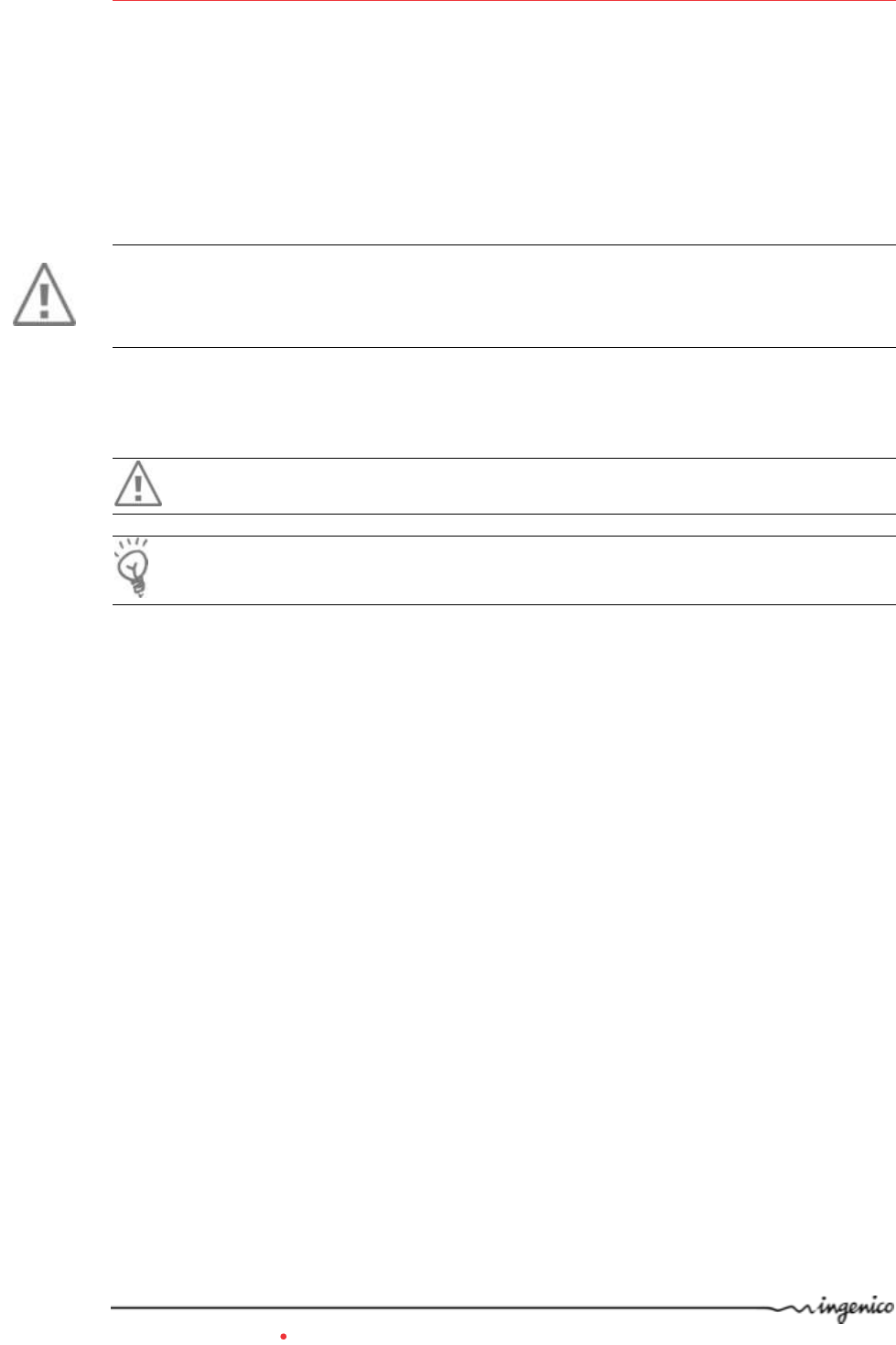
2.1.1. Terminal
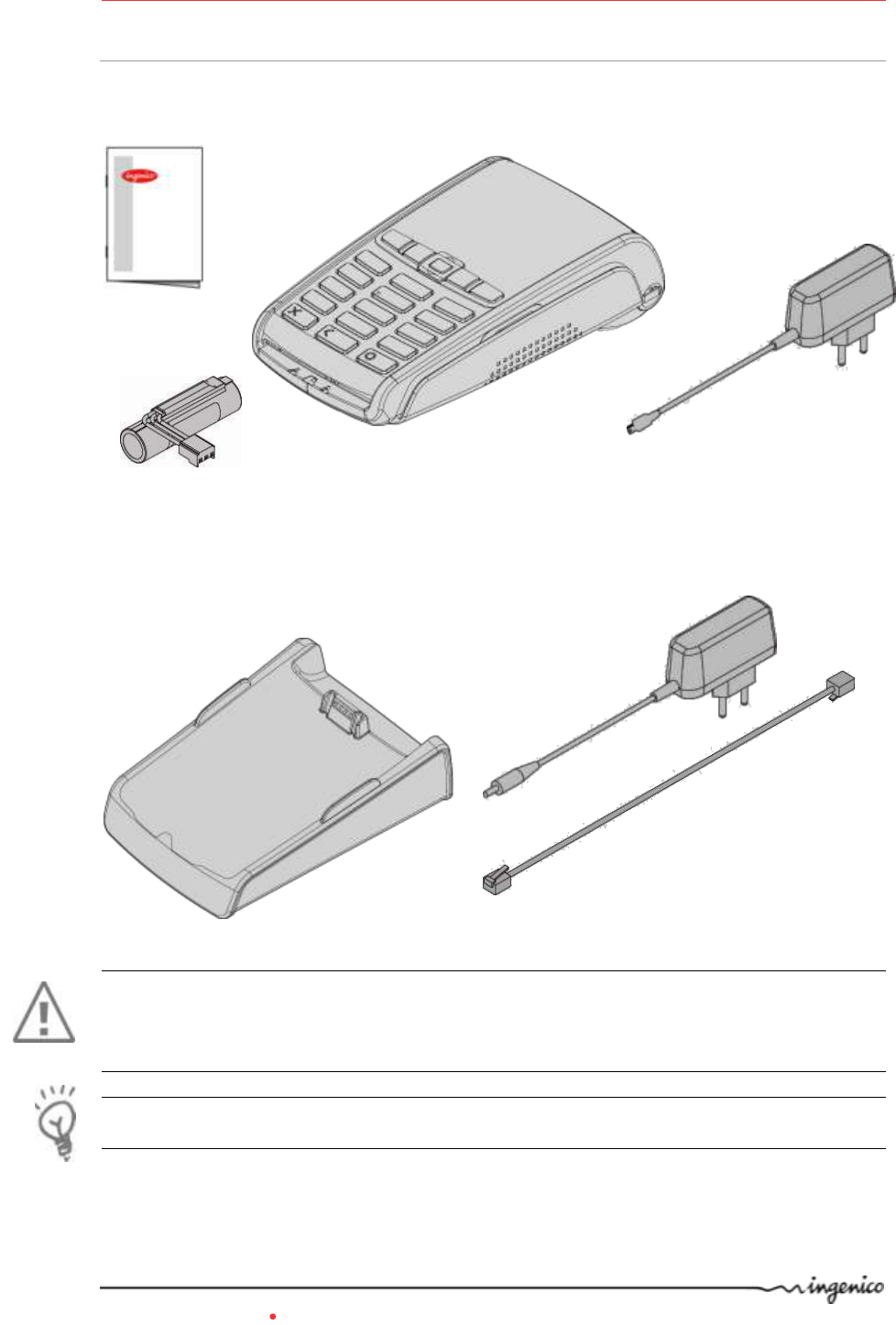
2.1.2. Base ( optional )
WARNING
The power supply unit provided with your equipment is specially designed for Ingenico
terminals. Do not use any other power supply. The use of a power supply with apparently
similar voltage/current characteristics may damage your terminal.
ADVICE
Keep the packaging. It must be re-used whenever the terminal is shipped.
IWL2XX terminal unit
equipped with a paper roll
Base
A power supply unit that
connect the base to the
mains network
A battery pack disconnected
A telephone cable
(with base modem)
Power supply unit (PSU)
(charging from the micro-USB
port of the terminal )
When the terminal is delivered
with a base, this PSU is
replaced by a base PSU
A user’s guide
iWL2xx Wireless Series 6/34 Copyright © 2013 Ingenico
900003061 R11 000 08/1324 All rights reserved
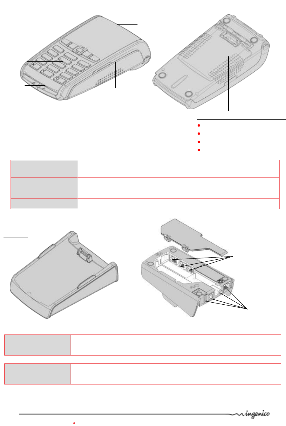
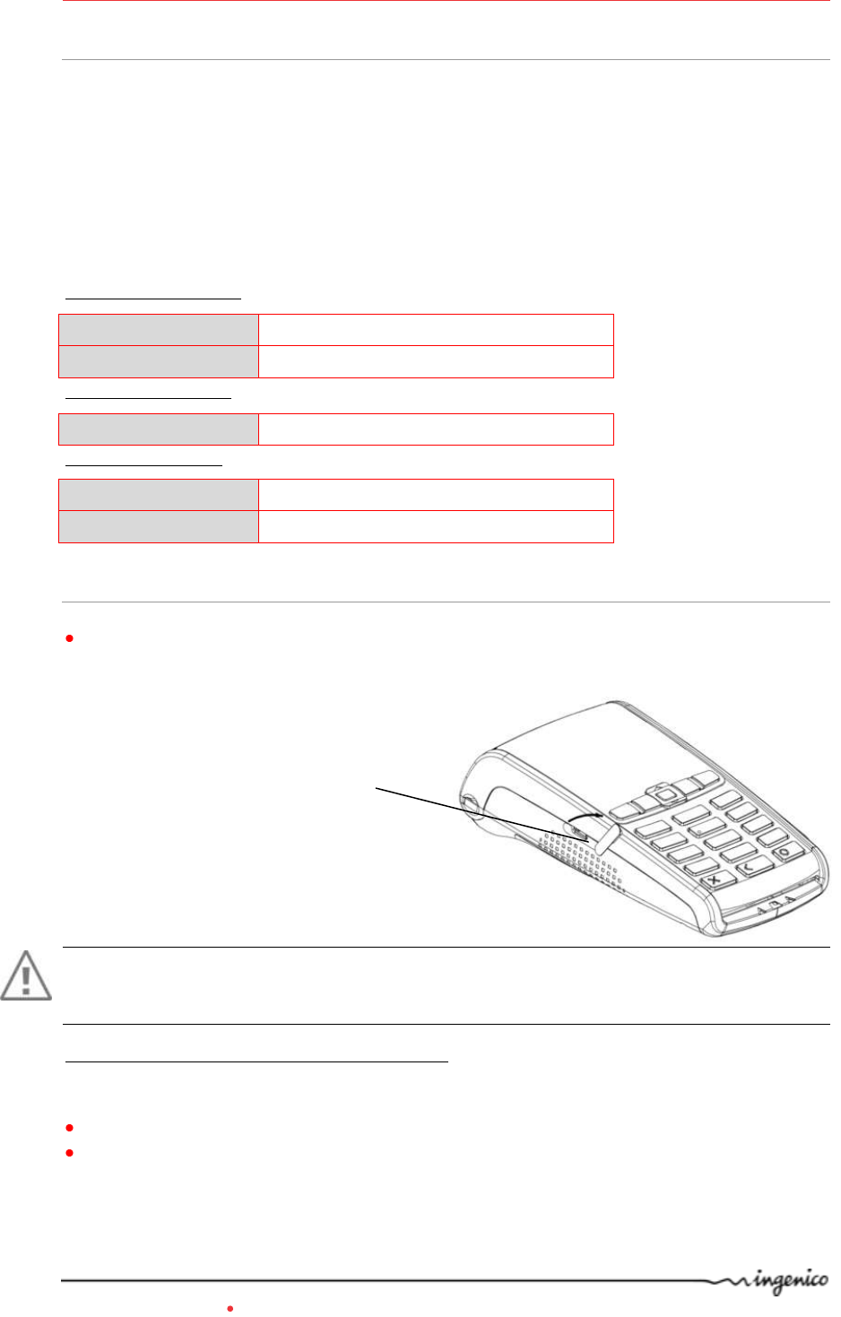
2.2. Overview of the iWL2XX
Base
Weight
About 150g
Dimensions (L x w x h)
140,7x87,7x45 mm
Power supply unit
Weight
About 100g
2pole sockets 1A (terminal power supply) or 1 A (base power supply)
Power supply units are specially fitted for INGENICO terminals.
Weight (without paper
roll nor battery)
285g for the R25 model and 300g for the R40 model
Dimensions (L x w x h)
150x76x44mmfor the R25 model and 164,5x76x53,5mm for the R40 model
Mains network
100-240VAC / 50-60 Hz - Class II equipment
Connections on terminal
Micro USB AB serial link
Backlit
keyboard
Smart
card reader
Easy loading printer
Large graphic display
Magnetic card
reader
Compartment where are located :
the battery pack
the SAM1/SAM2/SIM connector
the module microSD
the 2nd Smart card reader
Terminal unit
Base unit
External
links
External
links
iWL2xx Wireless Series 7/34 Copyright © 2013 Ingenico
900003061 R11 000 08/1324 All rights reserved
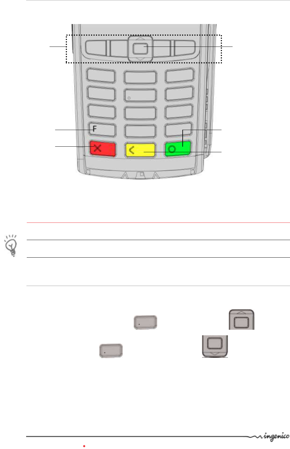
2.3. Keyboard details and functionality
Some keys can have other functions according to the applications that are in the terminal.
3. Use of the terminal
ADVICE
Before using the terminal, always check if the roll of paper is present.
3.1. Adjusting contrast (B&W display only)
If you wish to increase or to decrease the contrast of the characters displayed on black and
white display, press simultaneously and navigator UP key in order to
increase the contrast, or and navigator DOWN key in order to decrease
the contrast.
Keep pressing the keys as long as necessary.
The navigation keys
navigate in the
terminal menus
The function key
accesses the different
application menus
The red key cancels the
procedure in progress
The yellow key cancels the last
character. It can also advance
the paper a few centimetres if
pressed for a long time (more
than 2 seconds)
The green key validates input
selections and information.
It is also used to switch on the
terminal
Up/down and OK navigator
iWL2xx Wireless Series 8/34 Copyright © 2013 Ingenico
900003061 R11 000 08/1324 All rights reserved
3.2. Switching off the terminal
If the battery is empty and the terminal in use is removed from its base, the terminal
automatically shuts off.
It may also be forced stopped by pressing simultaneously and (yellow key)
for one second.
In order to restart the terminal, press (green key) on the keyboard.
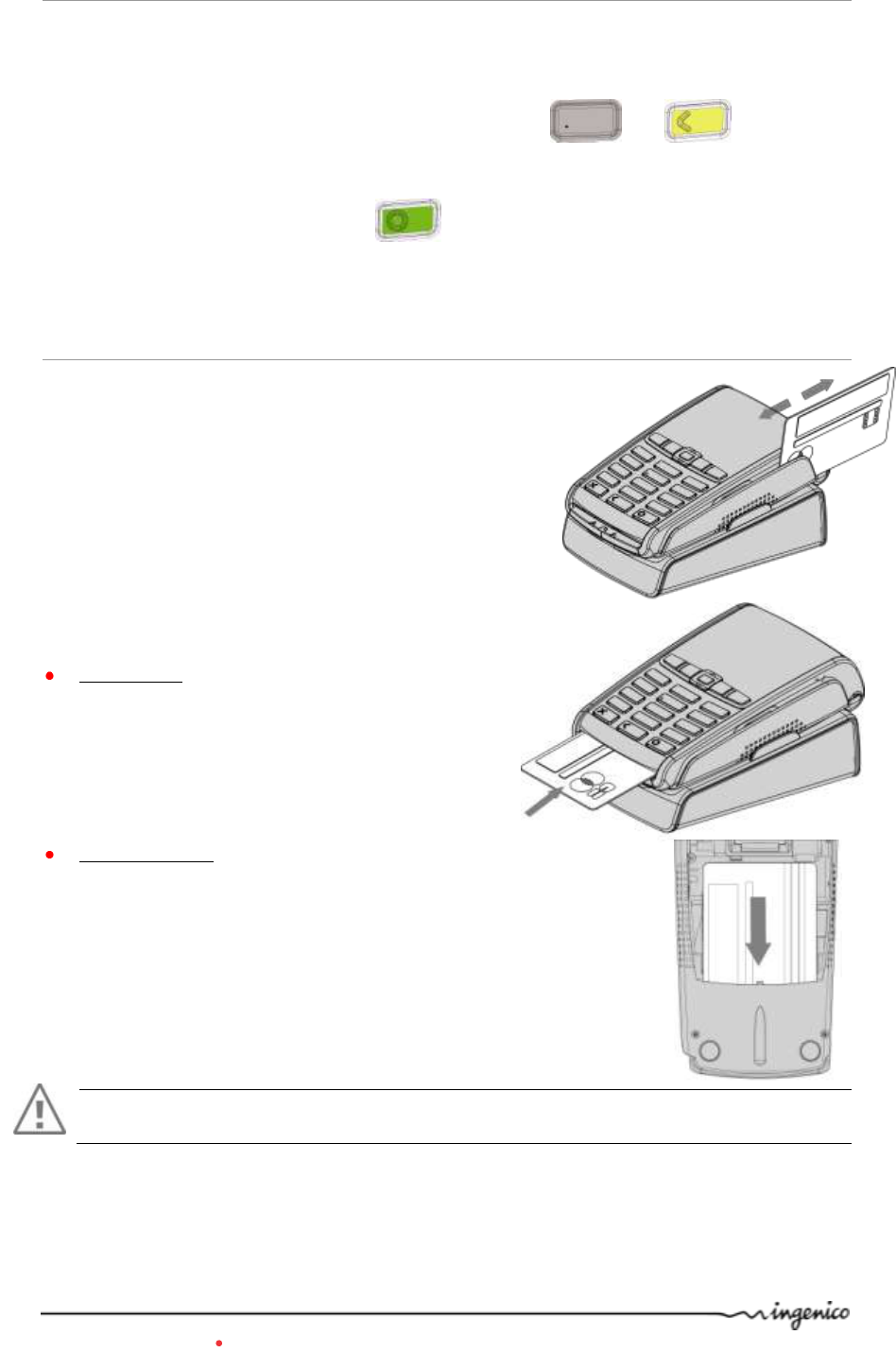
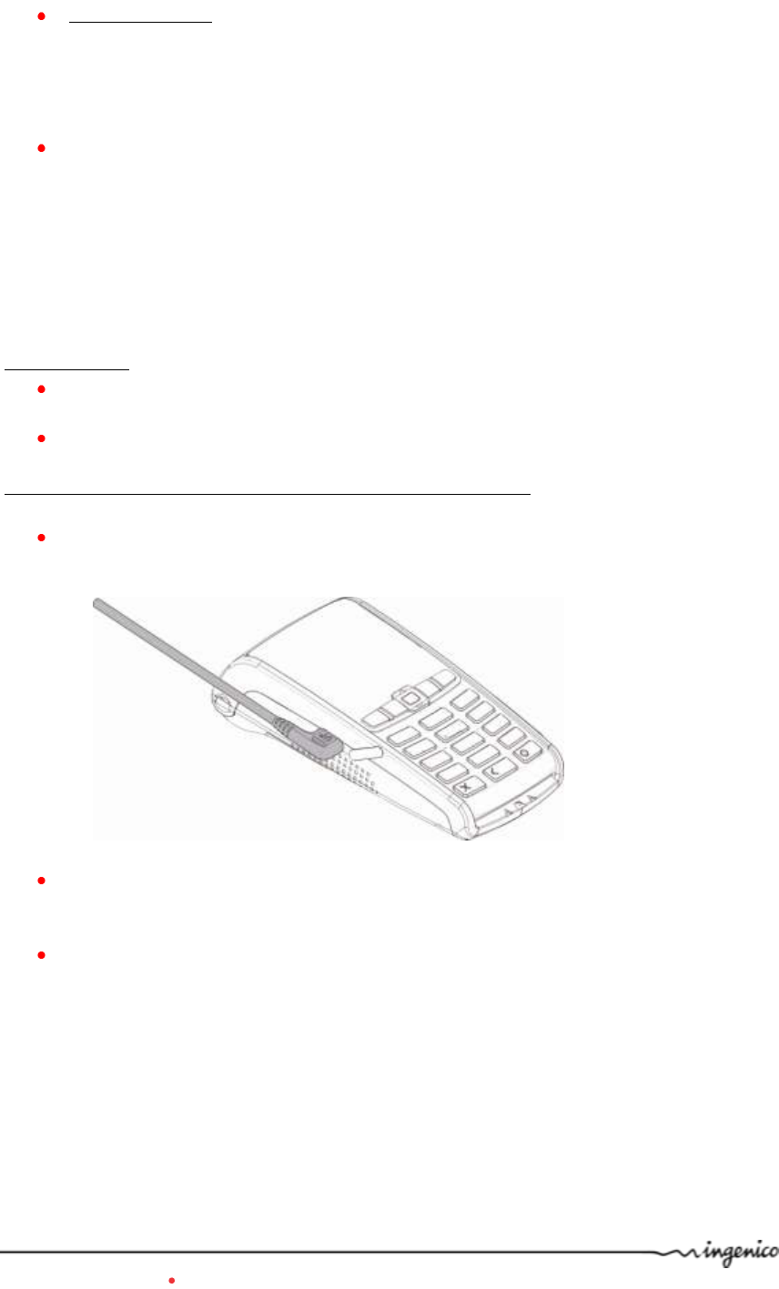
3.3. Reading cards
Magnetic stripe card
The card can be read either from bottom to top or from
topto bottom, with the stripe facing the terminal.
Use a regular movement in order to ensure a reliable
card reading.
Smart card
Card reader : insert the card horizontally with
the metal chip facing upward and leave in
position throughout the transaction.
2nd card reader (Optional) : is located under
terminal trapdoor (on back of the terminal). Insert the card up
side down, magnetic stripe visible.
Warning
Switch off the terminal before opening the trapdoor.
iWL2xx Wireless Series 9/34 Copyright © 2013 Ingenico
900003061 R11 000 08/1324 All rights reserved
Contactless (optional)
Bring the card firmly up to the active zone. Keep the
card close to the reader during the transaction
The 4 LEDs indicate transaction processing (as shown
on the picture) . On color screen terminal virtual LEDs
are displayed.
The terminal behavior for the cardholder may depend on:
The terminal environment
Local usage (language…)
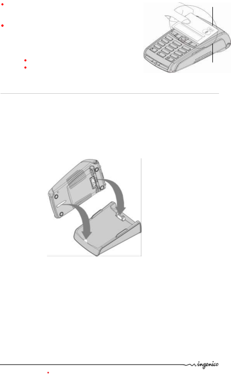
3.4. Installing the terminal on the base
Connecting the terminal on the base
Place the iWL2XX between the flanges on its base so that the contacts of the iWL2XX
engage on the contacts provided on the base (see picture below).
The base is designing to charge the terminal and to allow Ethernet or modem
communication.
4 leds
(B&W display only)
Active
zone
iWL2xx Wireless Series 10/34 Copyright © 2013 Ingenico
900003061 R11 000 08/1324 All rights reserved
4. Installation
4.1. Recommendations
Location of the iWL2xx
Place the base on flat surface near an electric socket and, if modem option, a telephone
socket. The terminal should be placed far from any very hot zones, protected from
vibrations, dust, damp and electromagnetic radiation (computer screen, anti-theft barrier
etc.).
The terminal must not be fixed to a counter in such a way that a user cannot pick up the
terminal and use his/her body to conceal the PIN when it is requested.
Operating conditions
Ambiant temperature
from -10°C to +45°C
Max relative humidity
85% at +40°C
Charging conditions
Ambiant temperature
from 0°C to +40°C
Storage conditions
Ambiant temperature
from -20°C to +55°C
Max relative humidity
85% at +55°C
4.2. Terminal connections
There is an USB connector (microAB) on the left side of the iWL2XX Wireless
terminal (see below picture). This connector manages Host or Slave connexions.
CAUTION :
Do not turn USB protection shell down side. Turn shell in clockwise direction to uncap
connector. And reverse to cap back
*MicroAB connector durability : up to 10000 mating cycles
The terminal supports USB Keys with FAT16 or FAT32
The USB Key has to be used with an USB adapter (refers to accessories section)
USB (microAB)
Connector used for PC, travel charger
adapter, USB Key, etc…)
iWL2xx Wireless Series 11/34 Copyright © 2013 Ingenico
900003061 R11 000 08/1324 All rights reserved
4.3. Installing Modules
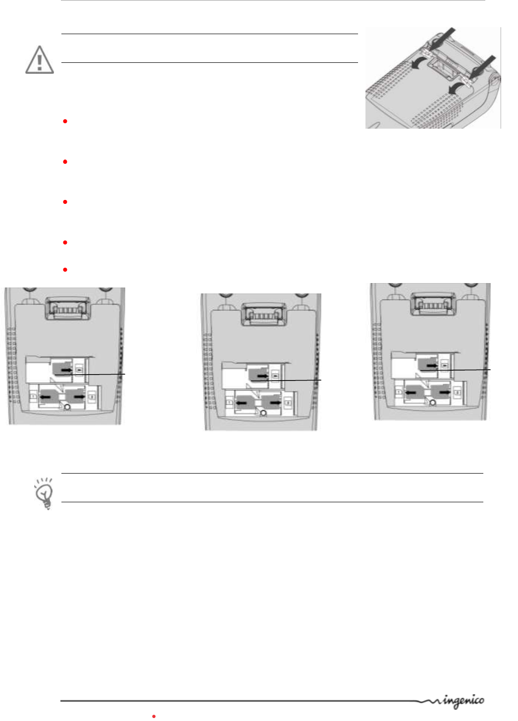
4.3.1. SAM1/SAM2/SIM
CAUTION :
Switch off the terminal before opening the trapdoor.
The SAM/SIM connectors are located inside the terminal,
in a closed compartment.
Turn the terminal and unclip the trapdoor by pushing on the
clips with your nails as shown with the arrows on the picture
SIM or SAM are identified by the engraved marks on the
lower housing or a dedicated label.
When introducing a SAM/SIM in its slot, be sure to put the
cut corner as indicated on the picture
Close the trapdoor.
SIM/SAM configuration available.
TIP
Use a piece of adhesive tape to grip the SAM for easier and faster removal.
Standard
Dual Sim option
SAM3 option
(Not available with GPRS)
Cut corner
position
SIM
SAM1
SAM2
Cut corner
position
SIM
SAM1
SIM2
Cut corner
position
SAM3
SAM1
SAM2
iWL2xx Wireless Series 12/34 Copyright © 2013 Ingenico
900003061 R11 000 08/1324 All rights reserved
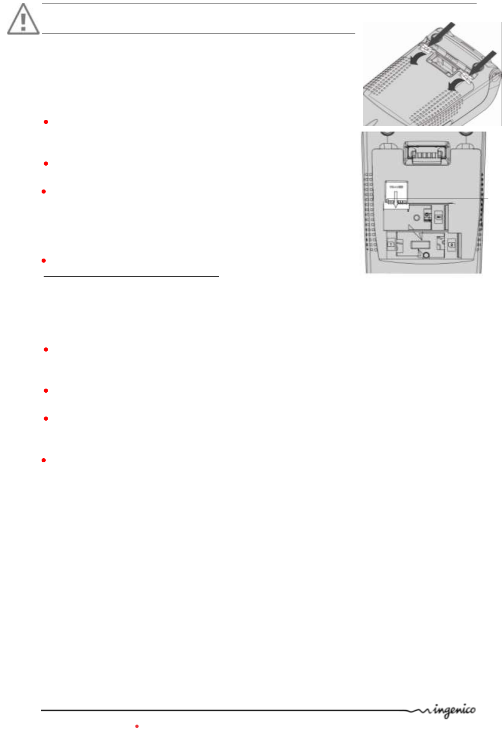
4.3.2. MicroSD Memory Card
CAUTION :
Switch off the terminal before opening the trapdoor.
MicroSD connector is located inside the terminal, in a closed
compartment.
To install a MicroSD Memory Card :
Turn the terminal and unclip the trapdoor by pushing on the
clips with your nails as shown with the arrows on the picture
Remove battery pack (disconnecting is not necessary).
Insert the MicroSD Memory Card into the connector slot as
shown on the figure.
Be sure to put the MicroSD contacts downside and the cut
corner as indicated on the figure.
Close the trapdoor
The terminal supports MicroSD up to 32GB
To remove a MicroSD Memory Card :
Turn the terminal and unclip the trapdoor by pushing on the clips
with your nails as shown with the arrows on the picture
Remove battery pack (disconnecting is not necessary).
Remove the MicroSD Memory Card. MicroSD connector has
push/pull ability . Push on MicroSD card edge to remove it.
Close the trapdoor
MicroSD card
Cut corner
position
iWL2xx Wireless Series 13/34 Copyright © 2013 Ingenico
900003061 R11 000 08/1324 All rights reserved
4.4. Paper roll
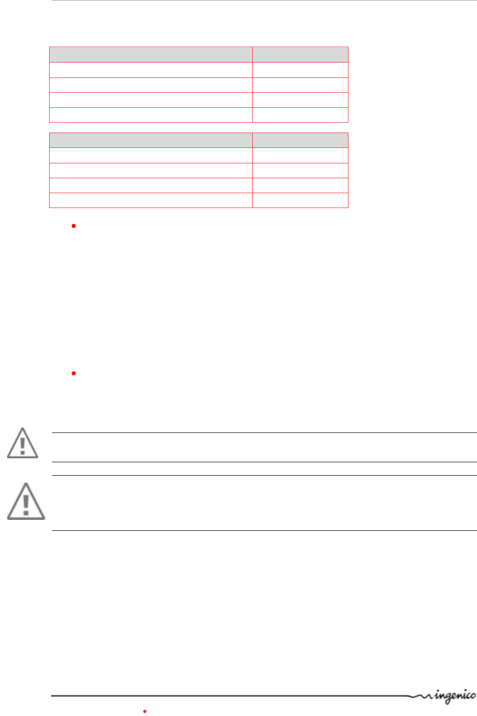
4.4.1. Mains characteristics of INGENICO paper roll
Depending on iWL model two paper roll can be used:
R40 paper roll Characteristics
Precisions
Colour
White
Width
58 mm
Diameter
40 mm
Length
About 18 metres
R25 paper roll Characteristics
Precisions
Colour
White
Width
58 mm
Diameter
25 mm
Length
About 9 metres
The thermal paper can be deteriorated by poor storage conditions, so we
recommend you to avoid :
– storage in hot wet places (near air-conditioner, humidity higher than 85%)
– exposure to sunlight or ultraviolet for long periods
– contact with organic solvents (solvent type adhesive)
– direct contact with materials containing plasticizers (PVC transparent
folders or envelopes)
– direct contact with «diazo» papers
– direct contact with water
– Rubbing or pressing the paper too strongly
Recommended paper:
AF50KS (Jujo), or F5041 (Mitsubishi), or TK50KS (Nippon_Paper), or equivalent.
WARNING
For best product performance, only use heat sensitized paper approved by Ingenico.
WARNING
Switch off the terminal prior to installing a paper roll.
Use only paper approved by Ingenico.
The use of non approved paper is likely to damage the printer of your terminal.
iWL2xx Wireless Series 14/34 Copyright © 2013 Ingenico
900003061 R11 000 08/1324 All rights reserved
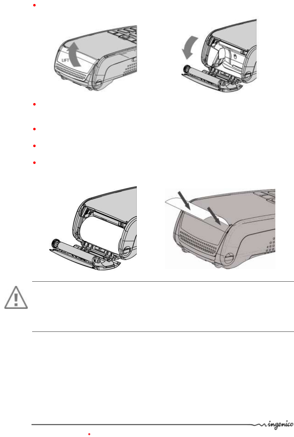
4.4.2. Installing paper roll
Open the paper compartment by lifting the catch located at the rear of the iWL2XX and
pull the cover to the rear of the terminal.
Insert the paper roll in the compartment following the directions shown on the below
picture
Pull the paper up to the top of the terminal
Maintain the paper and close the cover
Press simultaneously on both upper corners of the paper flap, as shown by red arrows
on picture, until it clips into position
WARNING
Use keyboard button to feed the paper, NEVER pull the paper by hand.
Do not try to tear the ticket by yanking the paper up or straight against the cutter (located
above the display).
Pull the ticket against the printer cutter at the angle (if using left hand, cut from right to
left, if using the right hand, cut from left to right).
iWL2xx Wireless Series 15/34 Copyright © 2013 Ingenico
900003061 R11 000 08/1324 All rights reserved
4.1. Battery
4.1.1. Main characteristics
Characteristics
Li-ion
Capacity
Up to 2250mAh
Charge
50% capacity in 1.5h; full capacity
in 4hours
Autonomy*
500 typical transactions
up to 250h in stand by
* depend on the terminal type and its base.
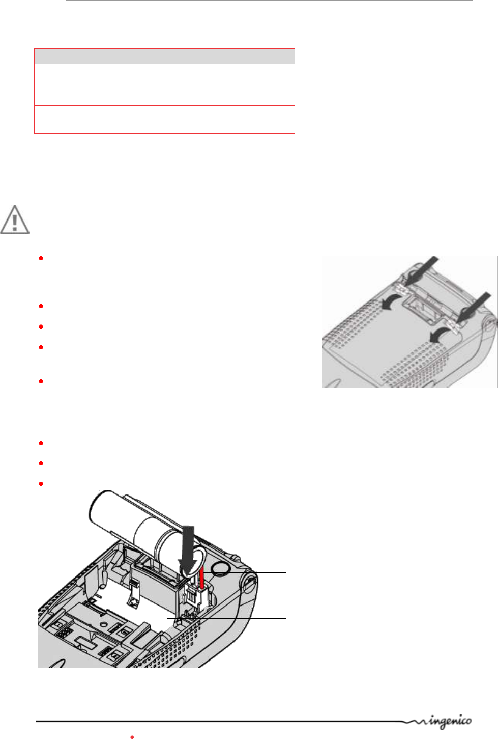
4.1.2. Installing the battery
WARNING
Switch off the terminal prior to connecting the battery.
Turn your terminal and unclip the battery trapdoor by
pushing on the clips with your nails as shown on the
picture
Disengage the trapdoor
Take the battery pack included in the box
Locate the battery pack connector beside the battery
compartment
Plug the battery pack connector according to the
connector locating system and the red wire (as
shown on picture).
Verify that it locks.
Place the battery pack in its compartment.
Check that the wires’ path is flat
Close the battery compartment trapdoor.
Red wire
Battery compartment
iWL2xx Wireless Series 16/34 Copyright © 2013 Ingenico
900003061 R11 000 08/1324 All rights reserved
4.1.3. Charging the battery
When does the battery need to be charged?
When used daily, the terminal recharges its batteries each time it is placed on its
base or each time the traveller charger is connected. Charging is automatic
How does the battery need to be charged?
The environment in which the charge takes place influences battery lifetime and
autonomy (number of transactions)
The optimal conditions are as follows:
Charging away from any external heat source (radiator, sun, enclosed area…)
The optimal temperature is between +15°C and +25°C.
50% capacity in 1.5h; full capacity in 4 hours.
How can the battery be charged?
Using the base
Place the terminal on its base
Check if the battery symbol is flashing or moving (=battery charging).
Using the power travel adapter (the terminal is out of its base)
Connect the traveller power supply unit to the terminal microAB connector located
on the left side of the terminal.
Connect the power supply unit to the power supply mains network
Check if the battery symbol is flashing or moving(=battery charging)
iWL2xx Wireless Series 17/34 Copyright © 2013 Ingenico
900003061 R11 000 08/1324 All rights reserved
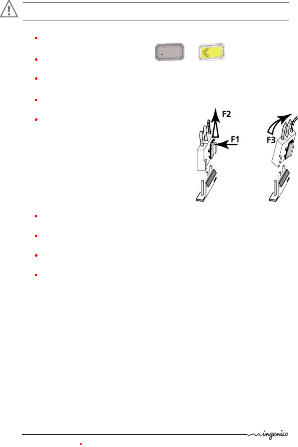
4.1.4. Changing the battery
It is imperative to use a battery authorized by Ingenico.
There is danger of explosion if battery used is not approved by Ingenico.
Remove the terminal from its base
Turn it off by pressing simultaneously and (yellow key) for
about one second
Remove the battery trapdoor (see section 4.1.2“installing battery”)
Lift the battery and remove it from its compartment
Carefully disconnect battery, following the
instructions below.
a) Unlock the connector by pressing the locking
mechanism as indicated by F1 arrow while pulling
wires (F2 arrow ), to disconnect the connector.
Release traction on it as soon as the connector
comes unclipped
b) Finish extracting connector by tilting it slightly
(F3 arrow) to bring it away from the terminal
housing
Connect and install the new battery by following the instructions in section 4.1.2
“Installing battery”
Close the battery trapdoor and charge the new battery. See section "0 “Charging
the Battery"
In order to preserve the environment, dispose used battery in compliance with
current country recycling legislation.
If the terminal is stored for a long time remove the battery from the terminal.

iWL2xx Wireless Series 18/34 Copyright © 2013 Ingenico
900003061 R11 000 08/1324 All rights reserved
5. Base
IXL2xx Base is available in different models. Please select by yourself in this documentation
items related to your model.
WARNING
Turn off base power supply unit before connection operation.
5.1.1. Base rear connections
WARNING
Select an electrical socket that complies with the general safety instruction given in section
6 “Recommendations” of this document.
Follow the below instructions :
Connect the power supply unit after all other connections.
Connect the power supply unit to the base socket B.
Connect the power supply unit to the mains network .
A = Ethernet socket (optional)
B= power supply unit socket
C = Path for wires.
D= USB Slave socket-CDC serial mode only (optional)
E = USB host Socket 1 (optional)
F = USB host Socket 2 (optional)
A
B
C
E
D
F
iWL2xx Wireless Series 19/34 Copyright © 2013 Ingenico
900003061 R11 000 08/1324 All rights reserved
Path for wires
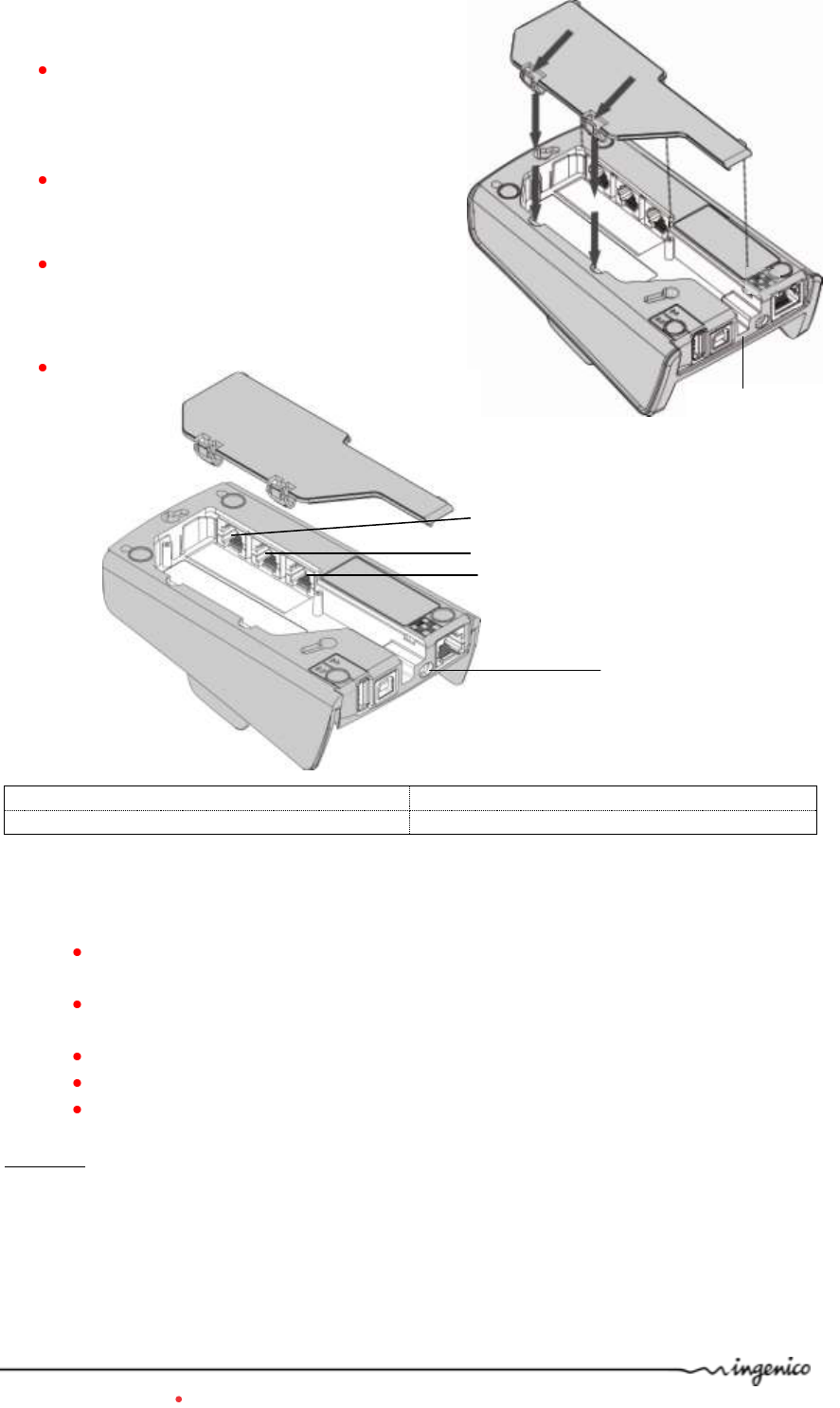
5.1.2. Base downside connections
Remove base trapdoor pushing on clips
( see clips location at red arrows)
Connect all downside connections
Use “path for wires” to
manage cable exit
Close trapdoor
G= Serial link COMØ – RS232 (optional) RJ11
H= Serial link COM1 – RS232 (optional) RJ11
I = Modem socket (optional) RJ11
Follow the below instructions to connect the base to the telephone network :
Disconnect power supply unit (socket B) in order to switch off the base prior to
connecting it to the appropriate network.
Connect telephone cable equipped if necessary with user country specific
telephone plug, to the telephone network.
Connect the other end of the wire to the base (socket I).
Connect the mains power supply wire to the base (socket B).
Connect base power supply block to the mains.
Socket I : TNV-3 circuit: Telecommunication Network Voltage, as per safety standard EN
60950-1.
G
H
I
B
iWL2xx Wireless Series 20/34 Copyright © 2013 Ingenico
900003061 R11 000 08/1324 All rights reserved
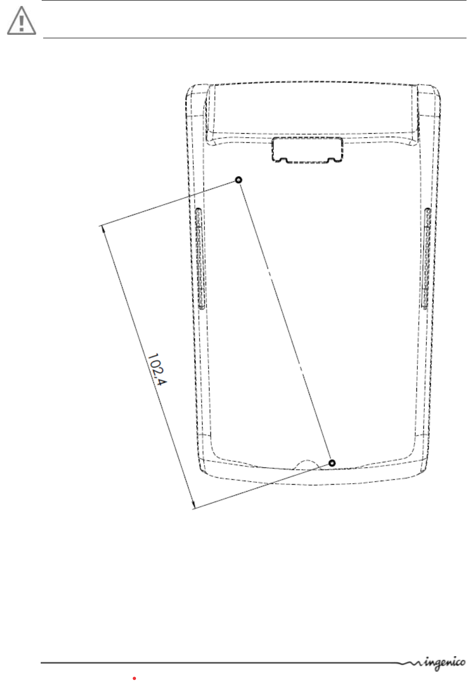
5.1.3. Fasten your base on desk
It is possible to fasten base on desk thanks to buttonholes located on base bottom casing.
Uses pattern beside to best locate screws position:
WARNING
Base must be set in horizontal position to insure terminal link work properly. This remains true when
buttonholes are used. Uses wall docking station accessory to fasten base in non horizontal position.
iWL2xx Wireless Series 21/34 Copyright © 2013 Ingenico
900003061 R11 000 08/1324 All rights reserved
6. Recommendations
6.1. Safety
Powering down the iWL2XX base :
Disconnect the iWL2XX power supply block adapter from the electrical mains
network.
Lithium cell (Backup battery)
The iWL2XX is fitted with an internal lithium cell which can only be accessed by a
qualified technician.
Battery
iWL2XX is fitted with battery specially designed for this terminal.
Only use the appropriate chargers and batteries listed in the Ingenico’s catalogue.
Do not short-circuit the battery.
Do not attempt to remove the battery housing as its components cannot be
modified.
Do not disassemble
Batteries in “end of life” must be disposed of at the appropriates sites.
The lifespan depends on:
Features
Cycle number of charge and discharge
Use temperature
Warning
There is a risk of explosion if the battery is incorrectly replaced.
Never place the battery next to a warmth source or in fire.
Electrical power outlet
The electrical outlet must meet the following criteria :
Must be installed near the equipment and easily accessible;
Must meet standards and regulations in the country where used;
The protection of the installation must be set to 20 A.
Telephone network
The phone jack must comply with standards and regulations in the country where
used.
iWL2xx Wireless Series 22/34 Copyright © 2013 Ingenico
900003061 R11 000 08/1324 All rights reserved
SAM1/SAM2/SIM readers compartment
The trapdoor for battery, SAM1/SAM2/SIM, readers located underneath the terminal,
must be in place during the normal operation of the terminal. See sections "Removal
of SAM1/SAM2/SIM, modules" as well as "Connecting the battery".
On airplanes
Your handset must be switched off by removing the battery pack. Remove the
battery from the terminal when on an airplane.
Non-compliance with these safety rules may result in legal action and/or a ban on
later access to cellular network services.
Explosion areas
Some regulations restrict the use of radio equipment in chemical plants, fuel depots
and any site where blasting is carried out. You are urged to comply with these
regulations. The terminal shall be protected by a specially fitted and certified cover
enabling use in proximity to a fuel pump.
Electronic health appliances
Your handset is a radio transmitter which may interfere with health appliances, such
as hearing aids, pacemaker, hospital equipment, etc.
Your doctor or the equipment manufacturer will be able to provide you with
appropriate advice.
6.2. Security of your terminal
Upon receipt of your terminal you should check for signs of tampering of the equipment. It
is strongly advised that these checks are performed regularly after receipt. You should
check, for example: that the keypad is firmly in place; that there is no evidence of unusual
wires that have been connected to any ports on your terminal or associated equipment, the
chip card reader, or any other part of your terminal. Such checks would provide warning of
any unauthorised modifications to your terminal, and other suspicious behaviour of
individuals that have access to your terminal. Your terminal detects any “tampered state”.
In this state the terminal will repeatedly flash the message” Alert Irruption!” and further
use of the terminal will not be possible. If you observe the “Alert Irruption!” message, you
should contact the terminal helpdesk immediately.
You are strongly advised to ensure that privileged access to your terminal is only granted to
staff that have been independently verified as being trustworthy.
CAUTION
NEVER ask the customer to divulge their PIN Code. Customers should be advised to ensure
that they are not being overlooked when entering their PIN Code.
The terminal must never be put in or left at a location where it could be stolen or replaced
with another device.
6.3. Telephone call
You have an urgent call to make while the iWL2XX is occupying the line.
In order to get a dial tone in short time:
Place the handset in the hang up position pressing the red key (=cancel)
or disconnect the base power supply from the mains network
or disconnect the iWL2XX telephone connector from the telephone call socket, and
place the telephone connector into the telephone wall socket.
You hear a dial tone within 6 seconds.
iWL2xx Wireless Series 23/34 Copyright © 2013 Ingenico
900003061 R11 000 08/1324 All rights reserved
7. Standards
CE Marking
The CE marking indicates iWL2xx complies with the requirements of European Directive
1999/5/EC of 9 March 1999 on Radio and Telecommunications Terminal Equipment for:
the protection of the health and the safety of the user and any other person.
the protection requirements with respect to electromagnetic compatibility.
and complies with harmonised standards.
Depending iWL2xx model involved standards are:
EN 60950-1 : 2006 + A11/2009 According to 2006/95/EC (Low Voltage Directive)
EN 55022 : 2006 + A1/2007 According to 2004/108/EC (EMC Directive)
EN 55024 : 1998+A1/2001 + A2 :2003 According to 2004/108/EC (EMC Directive)
EN 301489-1/7/24 : /2008 /2005/2007 According to 89/336/EEC (EMC Directive)
EN 301 511 : /12-2003 According to 1999/5/EC (R&TTE Directive)
EN 301 908-1 : /2010 According to 1999/5/EC (R&TTE Directive)
EN 62311 : /2008 According to 1999/519/EEC (R&TTE Directive)
EN 301489-1/17 : /2008/2009 According to 89/336/EEC (EMC Directive)
EN 300 328 : /2006 According to 1999/5/EC (R&TTE Directive)
EN 301489-1/3 : /2008/2002 According to 89/336/EEC (EMC Directive)
EN 302291 -1/2 : / 2005 According to 1999/5/EC (R&TTE Directive)
EN301893 : 2011 According to 1999/5/EC (R&TTE Directive)
EN 50357;EN50364 : /2001 According to 1999/519/EEC (R&TTE Directive)
EN 62479 / 2010
European approval specification on connecting terminals with DTMF dialling to the public
switched telephone network (Council Decision 1998/482/EC, Council Decision 1999/303/EC):
TS 103021-1/2/3 /09-2003 ES 203021 /1/2/3 (2006)
TR 103000-1/2/3/4 /06-2003
ES 201187 /03-1999
Safety instructions in the context of potentially
hazardous/explosive atmosphere in presence of gas according
European ATEX certification.
iWL22x and iWL25x are suitable in Zone 2 according the following ATEX certification
description
II 3G Ex ic IIA T3 Gc -10 °C < Tamb < +45 °C
Please read carefully the instruction guide before the installation in hazardous
location
Additional or different uses not indicated in the User or Maintenance Guide are not allowed
The equipments/electric components must not be open when energized.
The operation of terminal recharge must be executed in SAFE AREAS
Disconnect and replace the battery pack only in SAFE AREA
iWL2xx Wireless Series 24/34 Copyright © 2013 Ingenico
900003061 R11 000 08/1324 All rights reserved
The unauthorized replacement or non-original components compromise the safety of the
payment terminal. All the spare parts must be Ingenico original.
North American Hazardous Location Notification:
iWL22x and 25x are suitable for use in Class I, Division 2, Groups A – D hazardous (classified)
locations only.
WARNING: SUBSTITUTION OF COMPONENTS MAY IMPAIR SUITABILY FOR
DIVISION 2.
AVERTISSEMENT: LA SUBSTITUTION DE COMPOSANTS PEUT ENGENDRER UNE
NON-CONFORMITE SELON LA DIVISION 2.
iWL2xx Wireless Series 25/34 Copyright © 2013 Ingenico
900003061 R11 000 08/1324 All rights reserved
FCC/IC Compliance (Bluetooth model)
The FCC ID for IWL Bluetooth Terminal model (Model: IWL220-01T1426A) is: XKB-IWL2XXBPOS
and IC number is: 2586D-IWL220BPOS
The FCC ID for IWL Bluetooth Base model (Model: IWL200-01B1328A) is: XKB-IWL2XXBBASE and
IC number is: 2586D-IWL200BBASE
The FCC ID for IWL Bluetooth Contactless Terminal models ( Models IWL222-01T1488A and
IWL252-01T1535A) is: XKB-IWL2XXBCL and IC number is: 2586D-IWL2BCL
This device complies with Part 15 of the FCC Rules. Operation is subject to the
following two conditions:
(1) This device may not cause harmful interference, and
(2) This device must accept any interference received, including interference that may
cause undesired operation.
This device complies with Industry Canada licence-exempt RSS standard(s).
Operation is subject to the following two conditions:
(1) This device may not cause harmful interference, and
(2) This device must accept any interference received, including interference that may
cause undesired operation.
Le présent appareil est conforme aux CNR d'Industrie Canada applicables aux
appareils radio exempts de licence. L'exploitation est autorisée aux deux conditions
suivantes :
(1) l'appareil ne doit pas produire de brouillage, et
(2) l'utilisateur de l'appareil doit accepter tout brouillage radioélectrique subi, même si
le brouillage est susceptible d'en compromettre le fonctionnement.
This class (B) digital apparatus complies with Canadian ICES-003. / Cet appareil
numérique de la classe B est conforme à la norme canadienne ICES-003
Industry Canada as per DC-01 (Modem version)
This product meets the applicable Industry Canada technical specifications. / Le
présent matériel est conforme aux specifications techniques applicables d'Industrie
Canada.
The Ringer Equivalence Number (REN) is an indication of the maximum number of
devices allowed to be connected to a telephone interface. The termination of an
interface may consist of any combination of devices subject only to the requirement
that the sum of the RENs of all the devices not exceed five. / L'indice d'équivalence de la
sonnerie (IES) sert à indiquer le nombre maximal de terminaux qui peuvent être
raccordés à une interface téléphonique. La terminaison d'une interface peut consister
en une combinaison quelconque de dispositifs, à la seule condition que la somme
d'indices d'équivalence de la sonnerie de tous les dispositifs n'excède pas cinq.
The REN for 2586D-IWL200BBASE is: 0.4B
Part 68 of FCC Rules (for Modem version Only)
This equipment complies with Part 68 of the FCC rules and the requirements adopted by
the ACTA. On the bottom of this equipment is a label that contains, among other
information, a product identifier in the format US:AAAEQ##TXXXX. If requested, this
number must be provided to the telephone company.
iWL2xx Wireless Series 26/34 Copyright © 2013 Ingenico
900003061 R11 000 08/1324 All rights reserved
This equipment uses the following USOC jacks: (RJ11C).
A plug and jack used to connect this equipment to the premises wiring and telephone
network must comply with the applicable FCC Part 68 rules and requirements adopted by
the ACTA. A compliant telephone cord and modular plug is provided with this product. It is
designed to be connected to a compatible modular jack that is also compliant. See
installation instructions for details.
The REN is used to determine the number of devices that may be connected to a telephone
line. Excessive RENs on a telephone line may result in the devices not ringing in response to
an incoming call. In most but not all areas, the sum of RENs should not exceed five (5.0). To
be certain of the number of devices that may be connected to a line, as determined by the
total RENs, contact the local telephone company.
If this equipment causes harm to the telephone network, the telephone company will notify
you in advance that temporary discontinuance of service may be required. If advance notice
is not practical, the telephone company will notify the customer as soon as possible. Also,
you will be advised of your right to file a complaint with the FCC if you believe it is
necessary.
The telephone company may make changes in its facilities, equipment, operations, or
procedures that could affect the operation of this equipment. If this happens, the
telephone company will provide advance notice in order for you to make the necessary
modifications to maintain uninterrupted service.
If trouble is experienced with this equipment, please contact Ingenico, or your local
INGENICO distributor or service center in the U.S.A. for repair and/or warrant information. If
the trouble is causing harm to the telephone network, the telephone company may request
you to remove this equipment from the network until the problem is resolved. No repairs
can be done by a customer on this equipment.
Connection to party line service is subject to state tariffs. Contact the state public utility
commission, public service commission or corporation commission for information.
If your home has specially wired alarm equipment connected to the telephone line, ensure
the installation of this equipment does not disable your alarm equipment. If you have
questions about what will disable alarm equipment, consult your telephone company or a
qualified installer.
No changes shall be made to the equipment without the permission of Ingenico as
this may void the user’s authority to operate the equipment. / Tout changement
apporté à ce terminal non expressément approuvé par Ingenico est susceptible
d’annuler le droit de l’utilisateur à se servir de cet équipement.
Service Center Information
The service center to be contacted is:
INGENICO North America
79 Torarrie Road
M3L 1G5 Toronto Ontario
Fax : +1 416 245 6701 tel : +1 416 245 6700
iWL2xx Wireless Series 27/34 Copyright © 2013 Ingenico
900003061 R11 000 08/1324 All rights reserved
FCC/IC Compliance (GSM/GPRS/3G model)
The FCC ID for IWL GSM/GPRS Terminal model is: XKB-IWL2XXG
The FCC ID for IWL GSM/GPRS Contactless Terminal model is: XKB-IWL2XXGCL and IC number
is: 2586D- IWL2XXGCL
The FCC ID for IWL 3G Contactless Terminal model is: XKB-IWL2XX3GCL and IC number is:
2586D- IWL3GCL
This device complies with Part 15 of the FCC Rules. Operation is subject to the
following two conditions:
(1) This device may not cause harmful interference, and
(2) This device must accept any interference received, including interference that may
cause undesired operation.
NOTE: This equipment has been tested and found to comply with the limits for a Class B
digital device, pursuant to part 15 of the FCC Rules. These limits are designed to provide
reasonable protection against harmful interference in a residential installation. This
equipment generates, uses and can radiate radio frequency energy and, if not installed
and used in accordance with the instruction, may cause harmful interference to
radio communications. However, there is no guarantee that interference will not
occur in a particular installation. If this equipment does cause harmful interference
to radio or television reception which can be determined by turning the equipment off
and on, the user is encouraged to try to correct interference by one or more of the
following measures:
- Reorient or relocate the receiving antenna.
- Increase the separation between the equipment and receiver.
- Connect the equipment into an outlet on circuit different from that to which the
receiver is connected.
- Consult the dealer or an experienced radio/TV technician for help
In order to meet FCC and Industry Canada RF radiation exposure limits for general
population, this device must only be operated when held in the hand or in desktop
position with a minimum separation distance of at least 20cm from the user's body
and it must not be collocated or operated in conjunction with any other antenna or
transmitter. Use of this device with an accessory in order to be worn and operated
on user's body is strictly prohibited and will invalidate the certifications obtained for
FCC and Industry Canada.
Afin de respecter les directives de la FCC et d’Industrie Canada concernant les
expositions radiofréquence, cet appareil ne doit fonctionner que tenu dans la main
ou sur station d’accueil avec une distance minimale d’au moins 20cm du corps de
l’utilisateur et il ne doit pas être en colocation ou coopération avec une autre
antenne ou émetteur. L’utilisation de cet appareil avec un accessoire dans le but
d’être porté et fonctionné sur le corps de l’utilisateur est strictement prohibé et
invalidera les certifications FCC et Industrie Canada obtenues
This device complies with Industry Canada licence-exempt RSS standard(s).
Operation is subject to the following two conditions:
(1) This device may not cause harmful interference, and
(2) This device must accept any interference received, including interference that may
cause undesired operation.
iWL2xx Wireless Series 28/34 Copyright © 2013 Ingenico
900003061 R11 000 08/1324 All rights reserved
Le présent appareil est conforme aux CNR d'Industrie Canada applicables aux
appareils radio exempts de licence. L'exploitation est autorisée aux deux conditions
suivantes :
(1) l'appareil ne doit pas produire de brouillage, et
(2) l'utilisateur de l'appareil doit accepter tout brouillage radioélectrique subi, même si
le brouillage est susceptible d'en compromettre le fonctionnement.
This class (B) digital apparatus complies with Canadian ICES-003.
Cet appareil numérique de la classe B est conforme à la norme canadienne ICES-
003
No changes shall be made to the equipment without the permission of Ingenico as
this may void the user’s authority to operate the equipment.
Tout changement apporté à ce terminal non expressément approuvé par Ingenico
est susceptible d’annuler le droit de l’utilisateur à se servir de cet équipement.
iWL2xx Wireless Series 29/34 Copyright © 2013 Ingenico
900003061 R11 000 08/1324 All rights reserved
FCC/IC Compliance (WiFi model)
The FCC ID for IWL Wifi Terminal model (Model: IWL220-01T1426A) is: XKB-IWL2XXWBCL and
IC number is: 2586D-IWL2WBCL
THIS DEVICE COMPLIES WITH PART 15 OF THE FCC RULES. OPERATION IS SUBJECT
TO THE FOLLOWING TWO CONDITIONS: (1) THIS DEVICE MAY NOT CAUSE
HARMFUL INTERFERENCE, AND (2) THIS DEVICE MUST ACCEPT ANY INTERFERENCE
RECEIVED, INCLUDING INTERFERENCE THAT MAY CAUSE UNDESIRED OPERATION.
NOTE: THE GRANTEE IS NOT RESPONSIBLE FOR ANY CHANGES OR
MODIFICATIONS NOT EXPRESSLY APPROVED BY THE PARTY RESPONSIBLE FOR
COMPLIANCE. SUCH MODIFICATIONS COULD VOID THE USER’S AUTHORITY
NOTE: This equipment has been tested and found to comply with the limits for a
Class B digital device, pursuant to part 15 of the FCC Rules. These limits are
designed to provide reasonable protection against harmful interference in a
residential installation. This equipment generates uses and can radiate radio
frequency energy and, if not installed and used in accordance with the instructions,
may cause harmful interference to radio communications. However, there is no
guarantee that interference will not occur in a particular installation. If this
equipment does cause harmful interference to radio or television reception, which
can be determined by turning the equipment off and on, the user is encouraged to
try to correct the interference by one or more of the following measures:
- Reorient or relocate the receiving antenna.
- Increase the separation between the equipment and receiver.
-Connect the equipment into an outlet on a circuit different from that to
which the receiver is connected.
-Consult the dealer or an experienced radio/TV technician for help.
This device complies with Industry Canada licence-exempt RSS standard(s).
Operation is subject to the following two conditions:
(3) This device may not cause harmful interference, and
(4) This device must accept any interference received, including interference that may
cause undesired operation.
Le présent appareil est conforme aux CNR d'Industrie Canada applicables aux
appareils radio exempts de licence. L'exploitation est autorisée aux deux conditions
suivantes :
(1) l'appareil ne doit pas produire de brouillage, et
(2) l'utilisateur de l'appareil doit accepter tout brouillage radioélectrique subi, même si
le brouillage est susceptible d'en compromettre le fonctionnement.
This class (B) digital apparatus complies with Canadian ICES-003. / Cet appareil
numérique de la classe B est conforme à la norme canadienne ICES-003
The RF exposure information of the device are compliant with KDB 447498 D01
General RF Exposure Guidance v05r01.
iWL2xx Wireless Series 30/34 Copyright © 2013 Ingenico
900003061 R11 000 08/1324 All rights reserved
Environment (WEEE, Batteries and Packaging)
This product is labeled in accordance with European Directives 2002/96/EC concerning
Waste Electrical and Electronic Equipment (WEEE) and 2006/66/EC concerning Batteries
and Accumulators. Those provisions are requiring producers and manufacturers to become
liable for take-back, treatment and recycling upon end of life of equipment and batteries.
The associated symbol means that WEEE and waste batteries must not be thrown
away but collected separately and recycled.
Ingenico ensures that efficient collection and recycling schemes are set-up for WEEE and
batteries according to the local regulation of your country. Please contact your retailers for
more detailed information about the compliance solution in place for disposing of your old
product and used batteries.
Packaging waste must also be collected separately to assure a proper disposal and
recycling.
Please note that proper recycling of the electrical and electronic equipment and waste
batteries will ensure safety of human health and environment.
iWL2xx Wireless Series 31/34 Copyright © 2013 Ingenico
900003061 R11 000 08/1324 All rights reserved
8. Troubleshooting
The terminal does not turn on
Check the battery ( is it discharged ?, is it connected ?)
A full discharged battery can take long charging time to recover
Connect terminal to traveler power supply or put it on powered base
The terminal does not connect to the telephone line
Check the base power supply and telephone line cables
Check for base electrical power network
Check for Power On Ethernet network (POE powered base only: optional)
The terminal fails to establish a telephone connection
Check that the tone of the phone line is free
Check the configuration of the phone line and number to call
Get technical support
Cards are not read
Check if the magnetic card is swiped correctly (with magnetic stripe on terminal
side) .
Swipe again the card with the magnetic stripe movement constant and rapid
Check if the magnetic strip is not damaged, grooved or cracked
Make sure you have inserted correctly the smart card into the smart card reader
and removed the card only after the transaction is performed.
The ticket is not printed
Check the presence and proper positioning of the paper roll.
Possibly adjust the paper roll following the instructions in this manual (section 4.4
“Installing the paper roll”)
Check the type of paper used (thermal paper must be used)
Verify thermal paper sensitive side.
The ticket is printed slower than usually
Place the unit on the cradle or plug the USB cable in to charge the battery.
iWL2xx Wireless Series 32/34 Copyright © 2013 Ingenico
900003061 R11 000 08/1324 All rights reserved
9. Annex
Accessories list
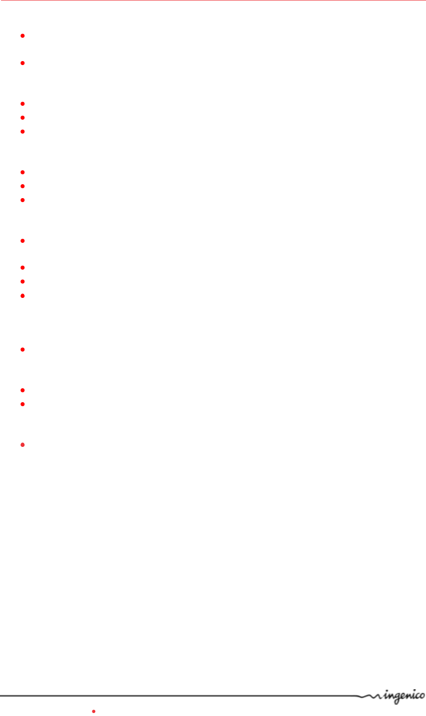
192013244 : Car charger 5V 0.75A µUSB iWL
296110863: Power travel adapter JACK/µUSB
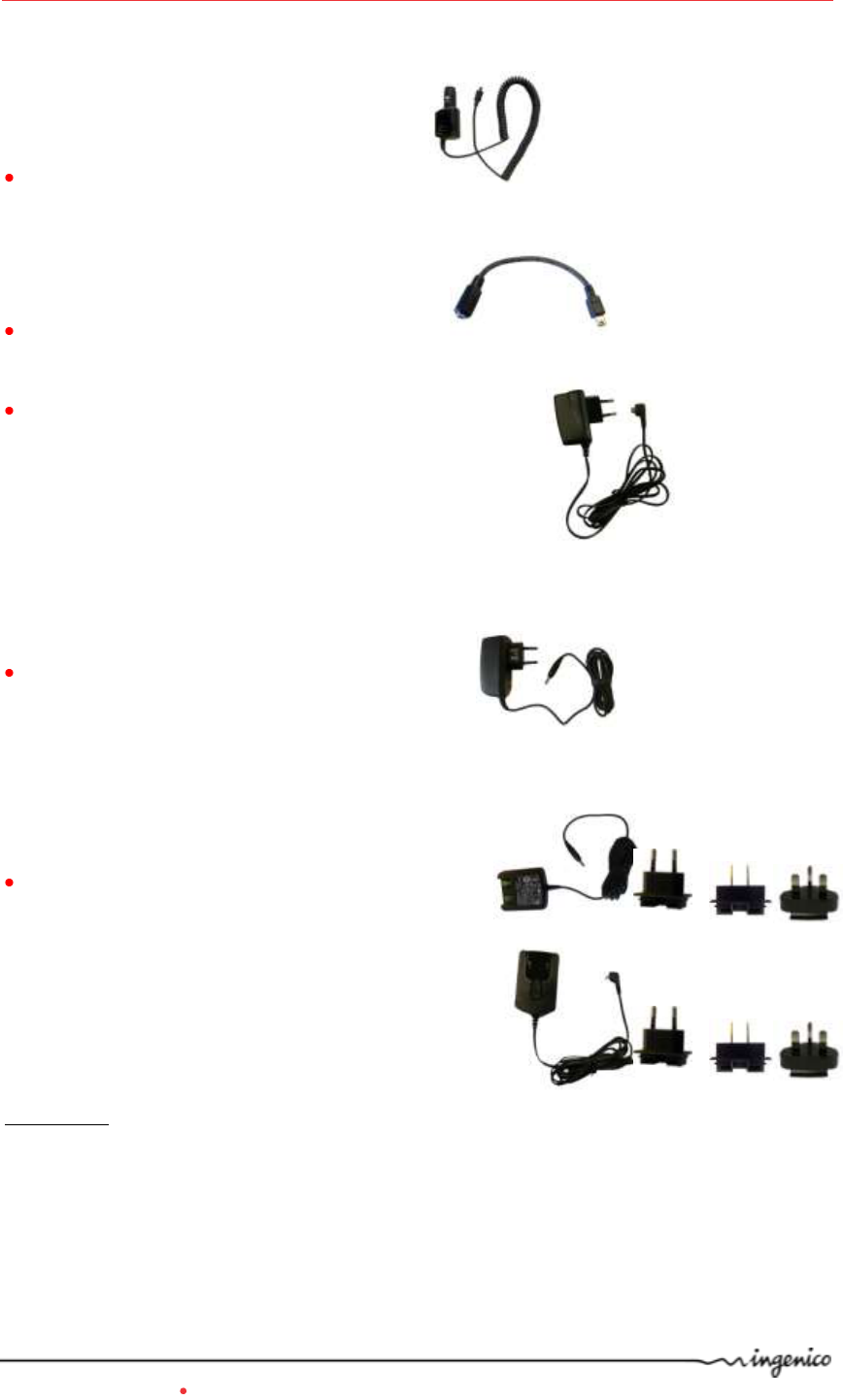
192010793 : CE traveler power supply unit (µUSB)
192010813 : UK traveler power supply unit (µUSB)
192010834 : US traveler power supply unit (µUSB)
192010855 : CHN traveler power supply unit (µUSB)
192010876 : AUS traveler power supply unit (µUSB)
192010579: CE base power supply unit (Jack)
192010582 : UK base power supply unit (Jack)
192010602 : US base power supply unit (Jack)
192010623 : CHN base power supply unit (Jack)
192010644 : AUS base power supply unit (Jack)
192011323 : Pack BA Multi EU/US/UK 5V 1A (Jack)
192011344 : Pack BA Multi EU/US/UK 5V 1A (µUSB)
Comments:
Using Power supply with Jack connector to charge the battery with the base.
Using Power supply with µUSB connector to charge the battery without the base (direct
connection to the µUSB connector of the terminal).
iWL2xx Wireless Series 33/34 Copyright © 2013 Ingenico
900003061 R11 000 08/1324 All rights reserved
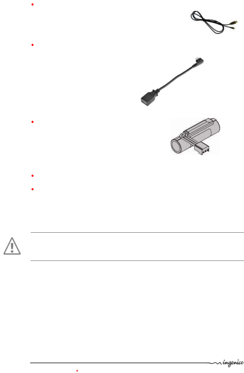
296109815: USB Cord (microB on terminal side USBA male on the other side) 1.5 m black
296130539: USB Cord (microA on terminal side USBA female on the other side) 0,15 m
black
295006044 : Battery pack Li-Ion standard
192034892 : Terminal (µUSB) car charger ALIM 11-32V/5V 675 mA
192034912 Base (Jack) car charger ALIM.11-32V/5V 675mA
WARRANTY / SECURITY
Use only the power supply included with the product to ensure best performance and
safety. Maintenance should only be provided by Ingenico authorized technician.
Failure to comply with these instructions will void the manufacturer’s responsibility.
iWL2xx Wireless Series 34/34 Copyright © 2013 Ingenico
900003061 R11 000 08/1324 All rights reserved
“This Document is Copyright © 2013 by INGENICO Group. INGENICO retains full copyright ownership,
rights and protection in all material contained in this document. The recipient can receive this
document on the condition that he will keep the document confidential and will not use its contents
in any form or by any means, except as agreed beforehand, without the prior written permission of
INGENICO. Moreover, nobody is authorized to place this document at the disposal of any third party
without the prior written permission of INGENICO. If such permission is granted, it will be subject to
the condition that the recipient ensures that any other recipient of this document, or information
contained therein, is held responsible to INGENICO for the confidentiality of that information.
Care has been taken to ensure that the content of this document is as accurate as
possible. INGENICO however declines any responsibility for inaccurate, incomplete or outdated
information. The contents of this document may change from time to time without prior notice, and
do not create, specify, modify or replace any new or prior contractual obligations agreed upon in
writing between INGENICO and the user.
INGENICO is not responsible for any use of this device, which would be non consistent with the
present document.
All trademarks used in this document remain the property of their rightful owners.”
Ingenico
28-32 Boulevard de Grenelle
75015 Paris - France
Tél: + 33 1 58 01 80 00
www.ingenico.com
Your contact
*2961159
20AH*