Ingenico L5000CLWIBT Standalone Payment terminal User Manual 900021971 R11 000 05 LANE 5000 indd
INGENICO Standalone Payment terminal 900021971 R11 000 05 LANE 5000 indd
Ingenico >
User Manual
Lane/5000
900021971 R11 000 05/0917 Copyright© 2017
Ingenico
All rights reserved
2
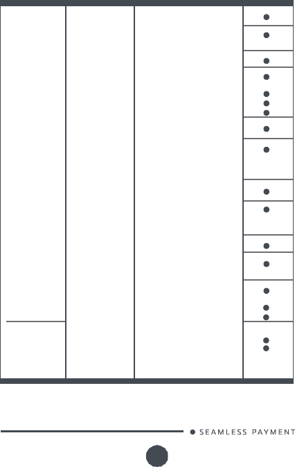
Contents
1_Introduction
2_Unpacking
3_Recommendations
3_1
Safety
3_2
Security of your terminal
(tampering attempt detection)
3_3 Main Characteristics
3_3_1
Terminal
3_3_2
Power characteristics
4_
Installation
4_1
Positioning the terminal
4_2 Connections
4_3
Installing the Terminal
4_3_1 Installing SAM (Secure access module,
optional)
4_3_2
Installing MicroSD Card (optional)
4_3_3
Connecting the terminal to the host
4_4
USB port (optional)
4_5
Stylus pen (optional)
4
5
10
6
12
7
9
12
19
14
15
9
6
13
14
16
19
Lane/5000
900021971 R11 000 05/0917 Copyright© 2017
Ingenico
All rights reserved
3
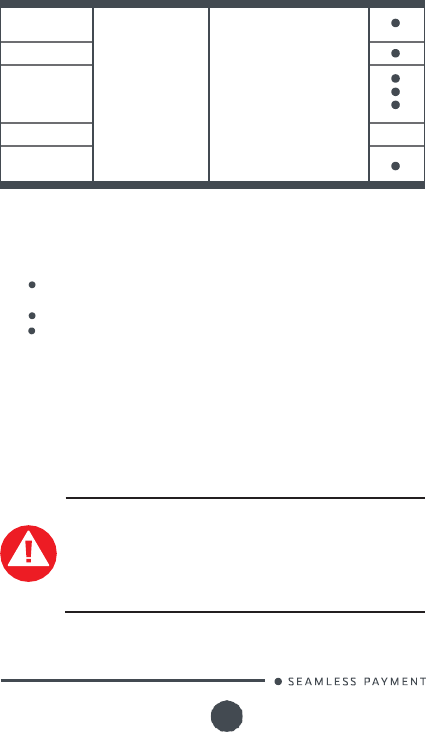
5_
Daily use
5_1 Card reading
5_1_1 Swiping a card
5_1_2 Inserting a smart terminal
5_1_3 Reading a contactless card
5_2 Keyboard details and functionality
5_3 Signature capture (optional)
5_4 Audio jack (optional)
6_
Maintenance
6_1
Cleaning of the terminal
6_2
Transport and storage
6_3
Troubleshooting
6_4
Environment
(WEE, Batteries and Packaging)
7_Standards
7_1 CE Marking
7_2
WARNING TO USERS IN THE
UNITED STATES
26
7_3
NO UNAUTHORIZED
27
MODIFICATIONS
7_4
ANTENNA REQUIREMENT
7_5
WARNING TO USERS IN THE
CANADA
25
26
20
20
20
23
20
20
21
22
22
23
24
24
26
27
27
Lane/5000
900021971 R11 000 05/0917 Copyright© 2017
Ingenico
All rights reserved
4
1_
Introduction
Thank you for choosing an Ingenico payment terminal.
We recommend you to read carefully this user guide: it gives you
the necessary information about safety precautions, unpacking,
installation and maintenance of your terminal.
WARRANTY /
SECURITY
To benefit from the guarantee-related product, and to
respect the security, we ask you to use only the Ingenico
power supply entrusting maintenance operations only to an
authorized person.
Failure to comply with these instructions will void the
m
a
n
u
f
a
c
t
u
r
er
’
s
r
e
s
p
o
n
s
i
b
i
l
i
t
y
.
This symbol indicates an important Warning.
This symbol indicates a piece of advice.
Lane/5000
900021971 R11 000 05/0917 Copyright© 2017
Ingenico
All rights reserved
5
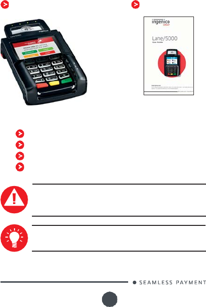
2_Unpacking
According to the model, the following items are included in the
packaging box (including optional accessories):
The terminal
The installation guide
The box may also include the following items depending on your
working configuration:
Cable (specific to your connectivity requirements)
Power supply unit and power cord
A stylus and its holder
Screws to fix the main cable and the trap door
CAUTION
The power supply unit provided with your equipment is
designed for it. It is certified with the Lane/5000. Do not
use any other power supply.
ADVICE
Keep the packaging.
It
must be re-used whenever the
terminal
is
shipped.
Lane/5000
900021971 R11 000 05/0917 Copyright© 2017
Ingenico
All rights reserved
6
3_Recommendations
3_1
Safety
Power on/Power down - Emergency stop
To power on or power down the terminal, connect or disconnect the
power supply from the electric outlet.
Power supply unit
CAUTION
Only use the power supply AC/DC provided with Lane/5000
(8VDC 2A, 8VDC 3A, 12VDC 2,5A or 8VDC 4A) or the power
provided by a cash register limited power source (LPS).
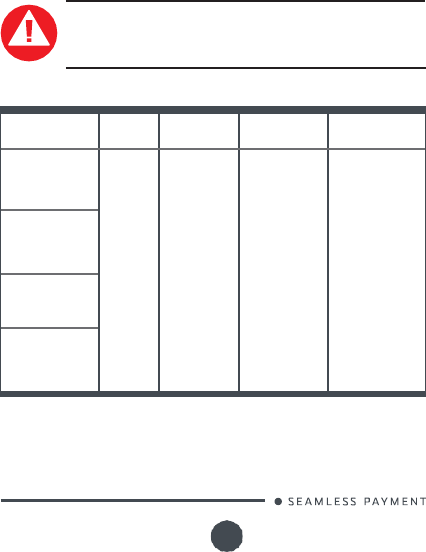
Authorized power supply units :
Power Supply
Unit Supplier
Type
Supplier
reference
Electrical
characteristics
Ingenico
part number
PHIHONG
TECHNOLOGY
Co. Ltd
Desktop
PSM32W-
080
8VDC 4A
Class V
296186619
PHIHONG
TECHNOLOGY
Co. Ltd
Wallplug
PSC16A-
080L6IN-R
PSC16E-
080L6IN-R
8VDC 2A
Class VI
296196003
296199611
PHIHONG
TECHNOLOGY
Co. Ltd
Desktop
PSM24W-
080L6IN-R
8VDC 3A
Class VI
296198809
PHIHONG
TECHNOLOGY
Co. Ltd
Desktop
PSAC30U-
120L6INA-R
12VDC 2,5A
Class VI
296204884AB
PSU class VI must be used in US.
Lane/5000
900021971 R11 000 05/0917 Copyright© 2017
Ingenico
All rights reserved
7
CAUTION
Use only the power supply specified for this product and
certified for the country of use. If the power supply is not
provided with the product, please contact your reseller.
Desktop Power Supply units have to be connected to the mains with
one of these cables:
Power cord 189609046 (European plug)
Power cord 188413214 (US plug)
CAUTION
Lithium battery cell
The terminal is fitted with a lithium battery cell which is
not accessible to the user. Only a qualified technician is
authorized to open the unit and change this component.
Risk
of explosion if the battery is replaced by an incorrect
type. Dispose of used battery according to the instructions.
Electrical power supply network
The electrical outlet must meet the following criteria;
Must be installed near the equipment and easily accessible;
Must meet standards and regulations in the country of use.
For type A plug, the protection of the installation must be set
to 20 A.
Explosion areas
C
e
r
t
a
i
n
r
e
g
u
l
a
t
i
o
n
s
r
e
s
t
r
i
c
t
t
h
e
u
s
e
o
f
r
a
d
i
o
eq
u
i
p
m
e
n
t
i
n
c
h
e
m
i
c
a
l
plants, fuel depots and any site where blasting is carried out. You are
urged to comply with these regulations. The terminal shall be protected
by a specially fitted and certified cover enabling use in proximity to a
fuel pump.
Bottom side compartment trapdoor
Located under the terminal, it must be in place during normal operation
of the device.
3_2
Security of your terminal
(tampering attempt detection)
Your device fulfils current applicable PCI PTS security requirements.
Upon receipt of your terminal you should check for signs of tampering
of the equipment. It is strongly advised that these checks are
performed regularly after receipt. You should check, for example: that
the keypad is firmly in place; that there is no evidence of unusual wires
that have been connected to any ports on your terminal or associated
equipment, the chip card reader or any other part of your terminal.
Lane/5000
900021971 R11 000 05/0917 Copyright© 2017
Ingenico
All rights reserved
8
Such checks would provide warning of any unauthorised modifications
to your terminal, and other suspicious behaviour of individuals that
have access to your terminal.
Your terminal detects any “tampered state”. In
this
state the terminal
will repeatedly flash the message” Alert Irruption!” and further use of
the terminal will not be possible. If you observe the “Alert Irruption!”
message, you should contact the terminal helpdesk immediately.
You are strongly advised to ensure that privileged access to your
terminal is only granted to staff that have been independently verified
as being trustworthy.
The terminal must never be put in or left at a location where it could be
stolen or replaced by another device.
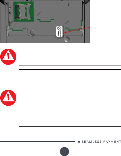
Warranty label
(under the
trapdoor)
WARNING
If
the warranty label is torn or removed, the warranty
will
be void.
CAUTION
Positioning of the Lane/5000 on check stand must be in
such a way to make cardholder PIN (Personal Identification
Number) spying infeasible.
Installing device on an adjustable stand must be in such a
way that consumers can swivel the terminal sideways and/
or tilt it forwards/backwards to a position that makes visual
observation of the PIN-entry process difficult.
Positioning of in-store security cameras such that the PIN-
entry keypad is not visible.
NEVER ask the customer to divulge their PIN Code.
Customers should be advised to ensure that they are not
being overlooked when entering their PIN Code
Lane/5000
900021971 R11 000 05/0917 Copyright© 2017
Ingenico
All rights reserved
9
3_3
Main Characteristics
3_3_1
Terminal
Processor
Application &
Crypto processor
Cortex A5 64 bits
Memory
Internal
External
512 MB Flash, 512 MB RAM
MicroSD up to 32GB
Option
OS
Telium Tetra OS
SAM
3
Cards readers
Magstripe
Smart card
Contactless
ISO 1/2/3, 500K lifespan
EMV Level 1, 500K lifespan
EMV Level 1 compliant
Display
Color
3.5" backlit LCD, HVGA
(480 x 320 pixels)
Touchscreen
Resistive
Capacitive
Finger & stylus (300k
lifespan
signature)
Finger & stylus (1000k lifes-
pan signature)
Option
Keypad
15 keys, raised Marking,
backlit
Audio
Buzzer
Audio jack
Speaker
Stereo
Mono
Option
Option
Video
Video accelerator
H264 codec
Terminal
connectivity
Wired
Ethernet 10/100 base T
Terminal
connections
USB
Serial
USB Host
2nd USB Host
USB Slave
1 R232
Option
Power supply
Powered USB
Powered R232
Powered Ethernet
External power
supply
5V
12V (USB retail)
12V
PoE 802.3af compliant
Option
Option
Option
Lane/5000
900021971 R11 000 05/0917 Copyright© 2017
Ingenico
All rights reserved
10
Terminal size
186x110x42 mm
(7.3x4.3x1.7")
Weight
350 g (12.3 oz)
Environment
Operating Temperature
Storage Temperature
Operating Humidity
0°C to 45°C (32°F to 113°F)
-20°C to +55°C (-4°F to 131°F)
85% non-condensing at +40°C
(104°F)
Accessory
Privacy shield
Factory mounted Option
Security
PCI PTS 4.x Online &
Offline ready
The terminal is intented for internal use only.
3_3_2
Power characteristics
The Lane/5000 can be powered by several ways:
An external power supply unit. See the list of the authorized
power supply units in §3_1 page 6.
By POE (Power over Ethernet)
By USB (5VDC or 12VDC)
POE (Power over Ethernet)
The power sourcing equipment must be compliant with IEEE802.3af
standard, class 0 which means 12.95W max. POE implementation in the
Lane 5000 can support both mode A and mode B.
USB
Lane/5000 needs 3.5W at 5V for good performances. Some options are
not supported at 5V (Dual head, camera, Wifi, Bluetooth).
WARNING
The Lane/5000 is not strictly compliant with standard USB
5V 500mA.
Functional test has to be performed with your equipment
to confirm that
it
can supply the required power and that
transactions can be done without issues.
If
not,
it will
be
necessary to use an external power supply unit.
Lane/5000
900021971 R11 000 05/0917 Copyright© 2017
Ingenico
All rights reserved
11
3_3_3
Terminal Connectivity
USB
High speed USB Device in the single connector
Ethernet
10/100 Base T Ethernet is available on the
Lane/5000. It is recommanded to use TCP Protocol
RS232
It is a 2 wire interface on the Lane/5000 (Rx/Tx). It
can run up to 115200bps
Lane/5000
900021971 R11 000 05/0917 Copyright© 2017
Ingenico
All rights reserved
12
4_
Installation
4_1
positioning the terminal
Install the terminal on
a
flat surface, with
an
easy
access
to
an
electrical
outlet. Place the terminal
away
from any
heat
source
and
protected
from dust, vibrations and electromagnetic radiations (away from video
terminals,
PC,
anti-shoplifting barriers
...).
The terminal is exclusively
made
for indoor use.
The Lane/5000 device may be mounted on a flat surface, wall, or
customer stand.
CAUTION
Do not place the Lane/5000 device on a PC monitor, adjacent
to an electronically active security tag deactivation system,
or near other sources of magnetic fields.
The Lane/5000 device must be at least 30 centimeters (12 inches)
away from an electronically active type of security tag deactivation
pad.
An electronically active system sends out a powerful and
potentially disruptive signal to deactivate the security tag. If
the Lane/5000 device
is
placed too close to the system’s pad, or
placed above the pad, the product may not work properly.
A passive system
is
a permanent magnet type that does not send
out a signal.
This
type should not affect the Lane/5000 device.
Operating conditions
Ambient temperature
from 0°C to +45°C
Max relative humidity
85% RH non-condensing at +40°C
Max altitude
2000 m
Storage conditions
Storage temperature -20°C, +55°C
Max relative humidity
85% at +55°C
This equipment should be installed and operated so that the
radiator is kept at least 20 cm or more away from a person’s
body excluding extremities.
Lane/5000
900021971 R11 000 05/0917 Copyright© 2017
Ingenico
All rights reserved
13
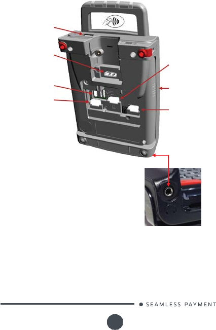
4_2
Connections
Here are all the connections on the terminal.
The SAMs and the Micro SD.
A type USB port
(Optional)*
Multipoint connector
(Power Supply and
communications)
µSD(Optional)*
SAM1 (Optional)*
*
according to the model
SAM2 (Optional)*
Speaker
(Optional)*
SAM3 (Optional)*
3.5mm audio jack
(Optional)*
Front view of the Audio Jack
Lane/5000
900021971 R11 000 05/0917 Copyright© 2017
Ingenico
All rights reserved
14
1
1
2
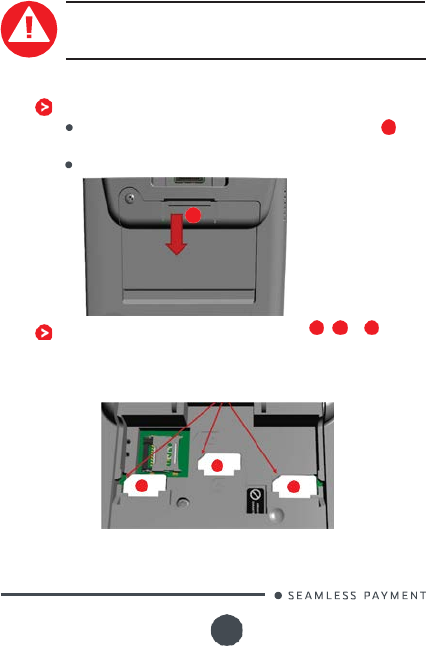
4_3
Installing the Terminal
4_3_1 Installing SAM (Secure access
module, optional)
CAUTION
Before starting, switch off the terminal by disconnecting the
cable.
Perform the following operations:
Open the trapdoor
Unclip the trapdoor by pushing down on the clip with
your finger as shown on the figure hereafter.
Then lift the trapdoor to remove it.
Insert the SAM Card into the slot marked , or
3
.
Take care to ensure that the SAM Card is inserted in the
correct manner. The cut corner must be positioned as
indicated on the figure below.
Cut corner
2
1
3
1
Lane/5000
900021971 R11 000 05/0917 Copyright© 2017
Ingenico
All rights reserved
15
1
Close down side trapdoor
To close the trapdoor, put the trapdoor onto the bottom
casing, and then push it upward to clip it.
CAUTION
Do not use any tools when installing or removing the SAM
Card.
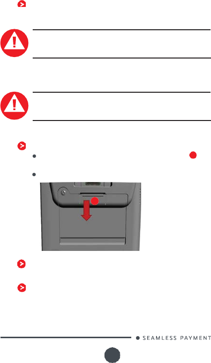
4_3_2
Installing MicroSD Card
(optional)
CAUTION
Before starting, switch off the terminal by disconnecting the
cable.
Perform the following operations:
Open the trapdoor
Unclip the trapdoor by pushing down on the clip with
your finger as shown on the figure hereafter.
Then lift the trapdoor to remove it.
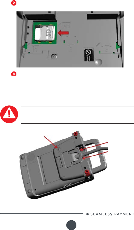
Slide the metallic part on the left and lift it up to open the
card holder, marked (SD)
Insert completely the MicroSD Card into the slot as indicated
on the figure.
The contacts must be positioned down side.
1
Lane/5000
900021971 R11 000 05/0917 Copyright© 2017
Ingenico
All rights reserved
16
Close down the card holder and push it to the right until it
clicks shut.
Close down side trapdoor.
Put the trapdoor onto the bottom casing, and then push it
upward to clip it.
4_3_3
Connecting the terminal to the
host
CAUTION
C
o
nn
e
c
t
i
n
g
mu
s
t
b
e
m
a
de
wh
e
n
t
h
e
t
e
r
m
i
n
a
l
i
s
p
o
w
e
r
ed
o
ff
.
Connector
screws (below
the handle,
optional)
Trapdoor screw
(optional)
Lane/5000
900021971 R11 000 05/0917 Copyright© 2017 Inge
nico
All rights reserved
17
Flip the terminal. There is one single port on the back for
power and communications.
Connect the cable on this port of the Lane/5000.
Connect the other end to the power supply unit.
Plug the power supply into the mains.
WARNING
The main port at the back must not be used to connect a
standard video HDMI cable.
Only connect cables validated for the Lane/5000 by
Ingenico.
Note:
screws can be added by the customer to hold more
firmly
the
trapdoor and the connector (refer to
their
locations on the figure
above).
The terminal can be connected to the host by several ways, with
optional cables :
High speed USB device
Ethernet
RS232
M
o
s
t
o
f
t
h
e
c
a
b
l
e
s
u
s
ed
w
i
t
h
i
S
C
a
n
d
i
PP
r
a
n
g
e
s
a
r
e
c
o
m
p
a
t
i
b
l
e
w
i
t
h
t
h
e
Lane/5000. We advise to check with your reseller their compatibility
if
y
o
u
p
l
a
n
t
o
r
ep
l
a
c
e
a
n
i
S
C
o
r
a
n
i
PP
b
y
a
L
a
n
e
/
5000
.
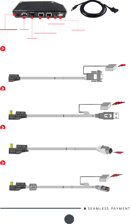
Following are some examples of accessories that can be used to
connect the Lane/5000.
This list is
not exhaustive. Please contact your
reseller for more information.
Com Box kit installation (optional)
Reference : 296148891AD
This installation kit includes a communication cable (ref.
296141785AC) to connect the terminal to the Com Box, which
dispatches on standard communication connectors :
2 USB ports (1 Host, 1 Device)
1
RS485 serial link (not usable on Lane/5000)
1 RS232 serial link
2
Ethernet ports
1 power lead
Lane/5000
900021971 R11 000 05/0917 Copyright© 2017
Ingenico
All rights reserved
18
Connector for terminal
Connector for terminal
Special USB Shielded cable
Connector for terminal
Power lead RS485
USB device
Ethernet ports
USB host
Connector
for terminal
RS232
RS232 cable (optional)
References: 296114811AB (length 2m)
296114928AB (length 5m)
Power supply unit
USB cable (optional)
References: 296111170AD (length 2m)
296114303AD (length 4m)
Power supply unit
USB powered 12V cable (optional)
References: 296178419AB (length 2m)
Connector for terminal
Special USB Shielded cable
Ethernet cable (optional)
Reference : 296114829AC (length 2m)
Power supply unit
Ethernet connector
12 V
Connector for terminal
Connector for terminal
Connector for terminal
Lane/5000
900021971 R11 000 05/0917 Copyright© 2017
Ingenico
All rights reserved
19
Part n
(grey S
4_4
USB port (optional)
There is an A type USB connector on the terminal, located on the rear
side, below the contactless antenna (see picture hereafter).
Open the rubber trap to access it.
This port manages Host connections, to connect an USB flash drive
or another device.
4_5
Stylus Pen (optional)
The stylus pen and its holder must be installed on the left side of
the terminal.
Remove the adhesive protection, insert the pin of the holder inside
the Kensington hole, and press firmly in place.
A magnet in the holder keeps the stylus in position.
Use the stylus type corresponding to the screen type (resistive or
capacitive)
Part numbers : 296219137 – for resistive stylus kit
(grey
oft Grip)
296219158 – for capacitive stylus kit (RED
Soft Grip)
WARNING
We recommend to the customer to provide guidance to
the cardholder as to avoid having
his
card close to any
magnets on the device since the card may be damaged.
There
is
one magnet
in
the
stylus
and another
in its
holder.
Lane/5000
900021971 R11 000 05/0917 Copyright© 2017
Ingenico
All rights reserved
20
5_
Daily use
5_1 Card reading
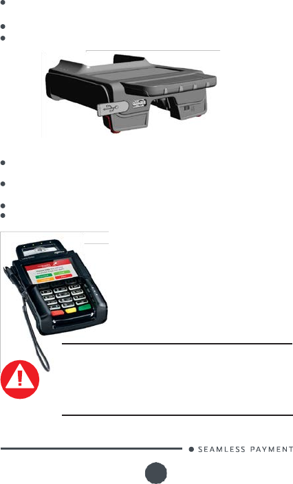
5_1_1 Swiping a card
Insert the card manually in the reader,
magnetic stripe facing the main body of
the terminal, and slide the card from the
rear to the front in a continuous motion for
best results.
When sliding the card through the reader,
make sure that the magnetic stripe on the
card
is
facing the Lane/5000 display screen
(see Swiping a Magnetic Stripe Card).
Swipe the card with constant speed, neither too slowly nor
too fast, to maximize the reading efficiency
5_1_2 Inserting a smart card
C
h
i
p
c
a
r
d
s
s
h
o
u
l
d
b
e
i
n
s
e
r
t
ed
i
n
t
o
y
o
u
r
terminal as illustrated with the chip facing
up and into the card reader.
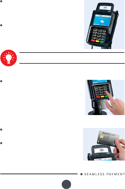
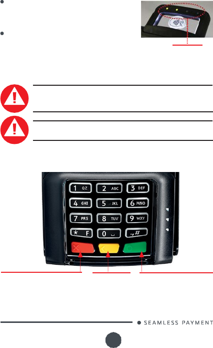
5_1_3 Reading a contactless card
Bring the card to the active zone above the
contactless logo (at about 1cm).
Keep the card close to the contactless logo
during the transaction.
Lane/5000
900021971 R11 000 05/0917 Copyright© 2017
Ingenico
All rights reserved
21
Your contactless reader provides four contactless status lights located
above the contactless logo.
When a contactless transaction
is
started
the
first
(left hand) status light
will
be
lit
steadily;
this
indicates that the contactless
is in
use but a card
is
not being read.
When a contactless card
is
presented
to the contactless active zone during a
transaction the second, third and fourth
status lights
will
be
lit
in turn. The card
read
is
successful when all four status lights
are
lit
and a confirmation tone can be
heard.
CAUTION
Contactless
status lights
Do not stick any label onto the contactless active zone. It
can decrease contactless efficiency.
CAUTION
Avoid metallic parts around the contactless area.
5_2
Keyboard details and
functionality
The red key cancels the procedure
in progress
The yellow key
cancels the last
character
The green key validates input
selections and information.
It is also used to switch on the
terminal
Lane/5000
900021971 R11 000 05/0917 Copyright© 2017
Ingenico
All rights reserved
22
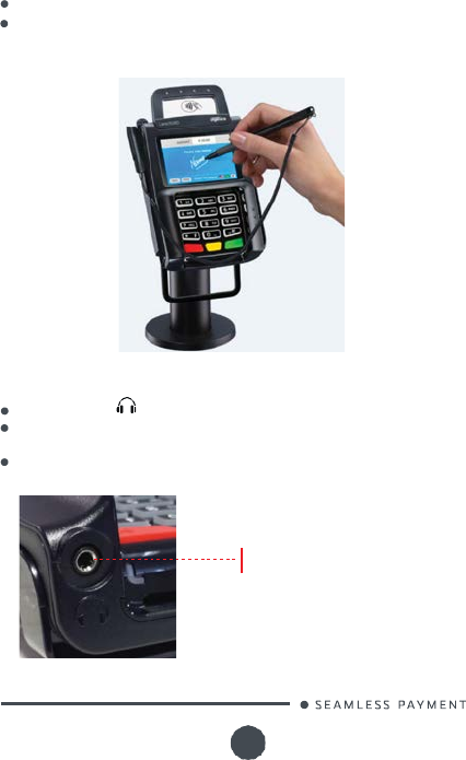
5_3
Signature capture (optional)
The signature capture is handled with the optional stylus.
Make sure that the correct stylus type (resistive or capacitive) is
used with the corresponding touchscreen type, as a resistive stylus
is not working with a capacitive screen.
5_4 Audio jack (optional)
The audio jack
is
located next to the smart card reader.
This
option is not designed to play music, but to facilitate the use of
the Lane/5000.
The audio connector
is
a standard 3.5mm Audio jack, (impedance
is
32 ohms)
audio
connector
Lane/5000
900021971 R11 000 05/0917 Copyright© 2017
Ingenico
All rights reserved
23
6_Maintenance
CAUTION
Before making any operations of maintenance in the
terminal, make sure that the power supply is disconnected.
6_1
Cleaning of the terminal
The outside of the terminals are susceptible to environmental
pollutants, as well as accidental spills or mishaps. It is just as important
to clean the outside of the Ingenico terminal, with a safe and approved
product, as it is to clean the inside. The Ingenico dual wipe has both
a
cleaning wipe for removing everyday contaminants and a dry wipe to
completely remove any remaining dirt or solution.
Clean equipment
will
function better then equipment that has been
neglected. When used properly, Ingenico cleaning cards and wipes
should prolong equipment
life
and minimize card read errors.
T
o
d
a
y
’
s
m
o
n
i
t
o
r
s
s
h
o
u
l
d
n
o
t
b
e
c
l
e
a
n
ed
w
i
t
h
s
t
a
n
d
a
r
d
g
l
a
ss
c
l
e
a
n
e
r
s
that contain chemicals too harsh for these sensitive screens: plasma
television screens, LCD and LED monitors, touch screen monitors
and POS screens all fall under this category. Ingenico dual wipes
are designed specifically for these type of monitors; removing dust,
fingerprints, oils or other contaminants that will distort the image
on your screen. The Ingenico dual wipe has both a cleaning wipe for
removing everyday contaminants and a dry wipe to completely remove
any remaining dirt or solution.
This product works best when the screen is cool, so before use turn the
monitor/system off.
This product can be used by anyone who can use a card reader
terminal, just:
•
Remove the Step 1 cleaning wipe
from
pouch.• Wipe down the screen
fi
r
s
t
,
t
h
e
n
t
h
e
k
e
y
p
a
d
,
t
o
p
a
n
d
s
i
de
s
o
f
t
h
e
t
e
r
m
i
n
a
l
.
•
R
e
m
o
v
e
t
h
e
St
ep
2
dry wipe
from
pouch.• Wipe down the screen
first,
then the keypad,
t
o
p
a
n
d
s
i
de
s
o
f
t
h
e
t
e
r
m
i
n
a
l
.
•
Y
o
u
m
a
y
u
s
e
bo
t
h w
i
pe
s
t
o
c
l
e
a
n
o
t
h
e
r
a
r
e
a
s
o
f
y
o
u
r
P
O
S
eq
u
i
p
m
e
n
t
i
f
n
e
c
e
ss
a
r
y
.
•
D
i
s
c
a
r
d
t
h
e
c
l
e
a
n
i
n
g
w
i
pe
s
properly.
For more information, visit our website http://ingenico.cleaningcards.
com
Lane/5000
900021971 R11 000 05/0917 Copyright© 2017
Ingenico
All rights reserved
24
CAUTION
Do not use
in any case,
solvents, detergents
or
abrasive
products:
those materials might damage the plastic or electrical
contacts.
Avoid exposing the terminal to the direct rays of the sun.
Do not put anything into the slot of the smart card reader
6_2
Transport and storage
Use the original packaging for storage or returning the unit.
Disconnect all cables from the terminal during the transport.
6_3
Troubleshooting
Device is not working
When sliding the card through the reader, make sure that the
magnetic stripe on the card
is
facing the Lane/5000 display
screen (see Swiping a Magnetic Stripe Card section 5.1.1)
Make sure that the Lane/5000 connector
is fully
inserted into
the back of the device.
Restart the device.
If you have another working Lane/5000 device, swap the
devices to determine if the problem is with the device, cable,
POS, or power supply.
If
the Lane/5000 device
is directly
connected to a host, reset
the host by
turning it
off and back on again.
Magnetic Card Reader Does Not Work Properly
Swipe the card at a faster or middle steady speed.
Inspect the magnetic stripe on the card to make sure
it is
not
damaged or badly worn.
Security tag deactivation system could disturb the magnetic
card reader
To determine if the problem is with the card :
a.
If your host device has a magnetic stripe reader, try
swiping the card there.
b.
If you have another working Lane/5000 device, try
swiping the card there.
Lane/5000
900021971 R11 000 05/0917 Copyright© 2017
Ingenico
All rights reserved
25
Smart Card Reader Does Not Work Properly
Make sure you have inserted correctly the smart card into
the smart card reader and removed the card only after the
transaction
MicroSD Card Reader Does Not Work Properly
Make sure you have inserted correctly the microSD card into
the card reader.
Check that the card capacity
is
not higher than 32GB.
Micro SD hotplug
is
not recomended.
Try
to reboot the
Lane/5000
Stylus Does Not Work Properly
Make sure you use the correct stylus version corresponding
to the screen type. A resistive stylus will not work on a
capacitive screen.
WARNING
Changes or modifications to this device not expressly
approved by the party responsible for compliance could
v
o
i
d
t
h
e
u
s
e
r
’
s
a
u
t
h
o
r
i
t
y
t
o
o
pe
r
a
t
e
t
h
e
eq
u
i
p
m
e
n
t
.
6_4 Environment (WEEE, Batteries and
Packaging)
This product is labelled in accordance with European Directives
2012/19/UE concerning Waste Electrical and Electronic Equipment
(WEEE) and 2006/66/EC concerning Batteries and Accumulators. Those
provisions are requiring producers and manufacturers to become liable
for take-back, treatment and recycling upon end of life of equipment
and batteries.
The associated symbol means that WEEE and waste
batteries must not be thrown away but collected
separately and recycled.
Ingenico ensures that efficient collection and recycling schemes are
set-up for WEEE and batteries according to the local regulation of your
country. Please contact your resellers for more detailed information
about the compliance solution in place for disposing of your old
product and used batteries.
Lane/5000
900021971 R11 000 05/0917 Copyright© 2017
Ingenico
All rights reserved
26
Packaging waste must also be collected separately to assure a proper
disposal and recycling.
Please note that proper recycling of the electrical and electronic
equipment and waste batteries
will
ensure safety of human health and
environment.
7_Standards
7_1
WARNING TO USERS IN THE
UNITED STATES
Federal Communication Commission Interference Statement 47 CFR
Section 15.105(b)
This
equipment has been tested and found to comply with the
limits
for a Class B digital device, pursuant to Part 15 of the FCC Rules. These
limits
are designed to provide reasonable protection against harmful
interference
in
a residential installation.
This
equipment generates uses
and can radiate radio frequency energy and,
if
not installed and used
in
accordance with the instructions, may cause harmful interference
to radio communications. However, there
is
no guarantee that
interference
will
not occur
in
a particular installation.
If this
equipment
does cause harmful interference to radio or television reception, which
can be determined by turning the equipment off and on, the user
is
encouraged to
try
to correct the interference by one of the following
measures :
Reorient or relocate the receiving antenna.
Increase the separation between the equipment and receiver.
Connect the equipment into an outlet on a
circuit different
from that
to which the receiver
is
connected.
7_2
NO UNAUTHORIZED MODIFICA-
TIONS
Federal Communication Commission Interference Statement 47 CFR
Section 15.21.
Consult the dealer or an experienced radio/TV technician for help.
CAUTION
This equipment may not be modified, altered, or changed in
any way without signed written permission from Ingenico.
Unauthorized modification may void the equipment
authorization from the FCC and
will
void the Ingenico
warranty.
Lane/5000
900021971 R11 000 05/0917 Copyright© 2017
Ingenico
All rights reserved
27
7_3
ANTENNA REQUIREMENT
Federal Communication Commission Interference Statement 47 CFR
Section 15.203.
This device complies with Part 15 of the FCC Rules. Operation
is
subject
to the following two conditions: (1) This device may not cause harmful
interference, and (2) this device must accept any interference received,
including interference that may cause undesired operation.
7_4
WARNING TO USERS IN THE
CANADA
This
device complies with Industry Canada licence-exempt RSS
standard(s). Operation
is
subject to the following two conditions : (1)
this device may not cause interference, and (2) this device must accept
any interference, including interference that may cause undesired
operation of the device.
Under Industry Canada regulations, this radio transmitter may only
operate using an antenna of a type and maximum (or lesser) gain
approved for the transmitter by Industry Canada.
To reduce potential radio interference to other users, the antenna
type and
its
gain should be so chosen that the equivalent isotropically
radiated power (e.i.r.p.)
is
not more than that necessary for successful
communication
7_5
Markings
The CE marking indicates that the terminal complies with harmonized
standards and requirements of European Directives on:
Radio and Telecommunications Terminal Equipment (R&TTE)
the protection of the health and the safety of the user and any
other person.
the protection requirements with respect to electromagnetic
compatibility.
RoHS (Restriction of Hazardous Substances)
T
h
e
C
E
m
a
r
k
i
n
g
i
s
t
h
e
m
a
n
u
f
a
c
t
u
r
e
r
’
s
de
c
l
a
r
a
t
i
o
n
t
h
a
t
the product meets the requirements of the applicable
EC directives. The CE mark is a mandatory conformity
marking for certain products sold within the European
Economic Area (EEA).
This TÜV symbol shows consumers at a glance that a
product has been examined by neutral experts and that
there are no safety concerns.
Lane/5000
900021971 R11 000 05/0917 Copyright© 2017
Ingenico
All rights reserved
28
The UL mark appears on end products and complete
components suitable for factory and field installation. All
of the products carrying these marks are coveredby our
Follow-Up Services program to determine that products
continue to be manufactured in compliance with UL’s
safety requirements.
The RCM mark
will
be the only mark to indicate compliance
w
i
t
h
t
h
e
A
u
s
t
r
a
l
i
a
n
C
o
mmu
n
i
c
a
t
i
o
n
s
a
n
d
M
ed
i
a
A
u
t
h
o
r
i
t
y
’
s
(ACMA) regulatory arrangements for telecommunications,
radio, EMC and electromagnetic energy (EME).
Double insulated or class 2 electrical appliances are
products that have been designed in a way so as not to
require a safety connection to electrical earth (These
products must NOT have a safety connection to Earth).
This logo indicates that the product operates with
a
continuous voltage. This symbol is followed by the ratings
(voltage
and
current for instance).
Indoor use symbol.
Mark indicating a power supply meets the Level VI
requirements.
I
n
d
i
a
’
s
C
o
m
p
u
l
s
o
r
y
R
e
g
i
s
t
r
a
t
i
o
n
S
c
h
e
m
e
(
C
R
S
)
f
o
r
Electronic Products.
This logo indicates that the product operates with an
alternative voltage. This symbol is followed by the ratings
(voltage and current for instance).
The Electrical Appliance and Material Safety Law applies
to enterprises that manufacture or import products in
Japan.
C
h
i
n
a
C
o
m
p
u
l
s
o
r
y
C
e
r
t
i
fi
c
a
t
i
o
n
(
CCC
)
i
s
s
i
m
i
l
a
r
t
o
o
t
h
e
r
certifications for product quality standardization–such as
the European CE system.

Lane/5000
900021971 R11 000 05/0917
29
Copyright© 2017 Ingenico
All rights reserved
“
T
h
i
s
D
o
c
um
e
n
t
i
s
C
o
p
y
r
ig
h
t
©
2015
b
y
I
N
G
E
N
I
C
O
G
r
o
u
p
.
I
N
G
E
N
I
C
O
retains
full
copyright ownership, rights and protection in all material
contained in this document. The recipient can receive this document
on the condition that he
will
keep the document confidential and
will
not use
its
contents in any form or by any means, except as agreed
beforehand, without the prior written permission of INGENICO.
Moreover, nobody is authorized to place this document at the disposal
of any third party without the prior written permission of INGENICO.
If
such permission
is
granted,
it will
be subject to the condition that
the recipient ensures that any other recipient of this document, or
information contained therein, is held responsible to INGENICO for the
confidentiality of that information.
Care has been taken to ensure that the content of this document is
as accurate as possible. INGENICO however declines any responsibility
for inaccurate, incomplete or outdated information. The contents of
this document may change from time to time without prior notice, and
do not create, specify, modify or replace any new or prior contractual
obligations agreed upon in writing between INGENICO and the user.
INGENICO is not responsible for any use of this device, which would be
non-consistent with the present document.
All trademarks used in this document remain the property of their
rightful owners.”
www.ingenico.com
28-32, boulevard de Grenelle, 75015 Paris - France / (T) +33 (0)1 58 01 80 00 / (F) +33 (0)1 58 01 91 35
Ingenico - SA au capital de 47 656 332 / 317 218 758 RCS Nanterre
Your contact