Ingenico M5000CLWIBT Mobile Payment terminal User Manual 900017771 R11 000 07 MOVE5000 indd
INGENICO Mobile Payment terminal 900017771 R11 000 07 MOVE5000 indd
Ingenico >
Contents
- 1. userguide_move3500
- 2. userguide_move5000
- 3. userguide_move5000.pdf
userguide_move5000
www.ingenico.com
28-32, boulevard de Grenelle, 75015 Paris - France / (T) +33 (0)1 58 01 80 00 / (F) +33 (0)1 58 01 91 35
Ingenico - SA au capital de 47 656 332 / 317 218 758 RCS Nanterre
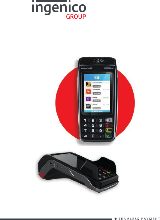
Move 5000
User Guide
Optional
Move 5000
900017771 R11 000 07/0117
Copyright© 2017 Ingenico
All rights reserved
2
Contents
1_Introduction
2_Presentation
2_1 Content of the box
2_1_1 Terminal
2_2 Overview on the MOVE/5000
2_3 Keyboard details and functionality
2_4 Touch panel
3_Use of the terminal
3_1 Switching off the terminal
3_2 Reading card
4_Installation
4_1 Recommendations
4_2 USB Terminal connections
4_2_1 uUSB
4_2_2 MicroSD Memory Card
4_3 Opening trap door
4_4 SAMs & SIMs
4
5
12
5
8
6
13
9
5
9
9
9
12
13
13
14
15
Move 5000
900017771 R11 000 07/0117
Copyright© 2017 Ingenico
All rights reserved
3
4_5 Battery
4_5_1 Main characteristics
4_5_2 Installing the battery
4_5_3 Charging the battery
4_5_4 Changing the battery
4_6 Paper roll
4_6_1 Main characteristics of INGENICO paper roll
4_6_2 Installing paper roll
5_Recommendations
5_1 Safety
5_2 Security of your terminal
5_3 Fixed installation
6_Standards
6_1 Environment (WEEE, Batteries and
Packaging)
6_2 FCC/IC Compliance
7_Troubleshooting
16
16
16
18
19
20
20
21
22
22
23
25
24
25
25
30
Move 5000
900017771 R11 000 07/0117
Copyright© 2017 Ingenico
All rights reserved
4
1_Introduction
We hope that you will be fully satised with your new terminal
MOVE/5000. This terminal is available in different models. Please
select by yourself in this documentation items related to your model.
Read this guide to understand and make the best use of your terminal.
It presents you the necessary information about use, installation,
maintenance, safety and security recommendations.
WARRANTY / SECURITY
Use only the power supply included with the product to
ensure best performance and safety. Maintenance should
only be provided by Ingenico authorized technician.
Failure to comply with these instructions will void the
manufacturer’s responsibility.
This symbol indicates an important Warning.
This symbol indicates a piece of advice.
Move 5000
900017771 R11 000 07/0117
Copyright© 2017 Ingenico
All rights reserved
5
2_Presentation
WARNING
The power supply unit provided with your equipment
is specially designed for Ingenico terminals. Do not use
any other power supply. The use of a power supply with
apparently similar voltage/current characteristics may
damage your terminal.
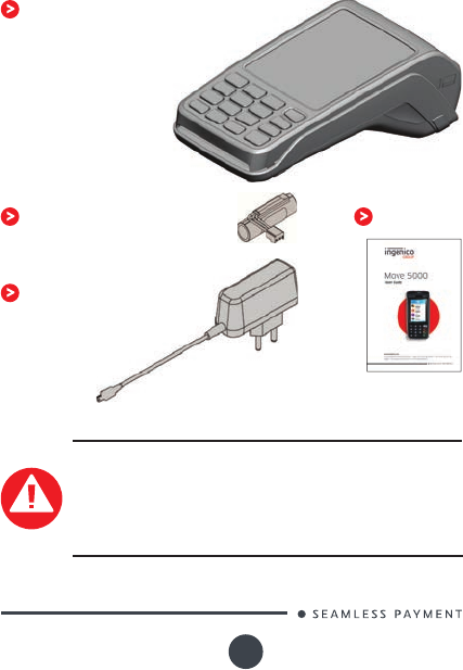
2_1 Content of the box
2_1_1 Terminal
MOVE/5000 terminal unit equipped
with a paper roll
A battery pack disconnected
Power adapter
User guide
Move 5000
900017771 R11 000 07/0117
Copyright© 2017 Ingenico
All rights reserved
6
ADVICE
Keep the packaging. It must be re-used whenever the termi-
nal is shipped.
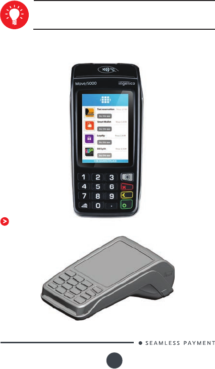
2_2 Overview of the MOVE/5000
Terminal unit
3’’5 LCD Display with
touch panel
Backlit keyboard
Smart card reader
Easy loading printer
Magnetic
card reader
Move 5000
900017771 R11 000 07/0117
Copyright© 2017 Ingenico
All rights reserved
7
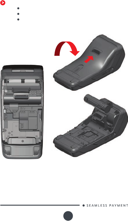
Compartment where are located:
the battery pack
the modules SAM1/SAM2/SIM1/SIM2
the 2nd Smart card reader (optional)
Move 5000
900017771 R11 000 07/0117
Copyright© 2017 Ingenico
All rights reserved
8
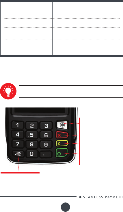
2_3 Keyboard details and functiona-
lity
Weight
(without paper roll nor
battery)
310g
Dimensions (L x w x h) 169x78x57 mm
Electrical mains network 100-240VAC / 50-60 Hz - Class II
equipment
Connections on terminal
Micro USB AB serial link
Power connector
Contacts for Cradle
Some keys can have other functions according to the appli-
cations that are in the terminal.
The functions key accesses
the different application
menus
The red key cancels the
procedure in progress
The yellow key cancels the
last character
The green key validates input
selections and information.
It is also used to switch on
the terminal
Feed paper a few centimers
if pressed for a long time
(more than 2 seconds)
Move 5000
900017771 R11 000 07/0117
Copyright© 2017 Ingenico
All rights reserved
9
2_4 Touch panel
The Move/5000 device is equipped with touch panel that allows you
capture functions and menus by your nger or using a stylus.
3_Use of the terminal
3_1 Switching off the terminal
ADVICE
Before to use the terminal, always check if the roll of paper
is present.
If the battery is empty and the terminal in use is removed from its
base, the terminal automatically shuts off.
It may also be switch by pressing simultaneously and (yellow
key) for one second.
In order to restart the terminal, press on the keyboard.
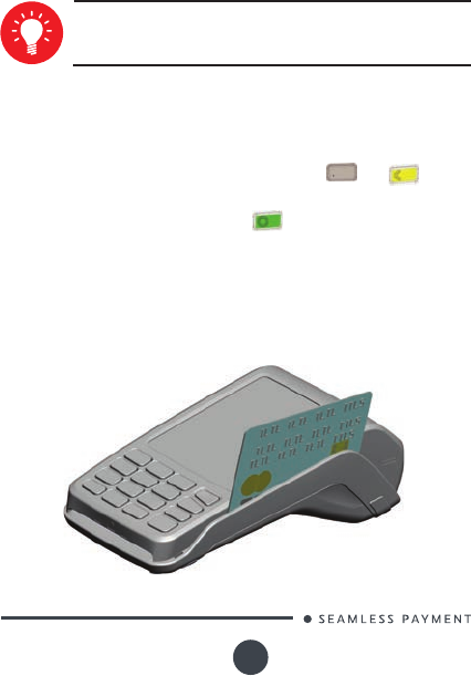
3_2 Reading card
The card can be read either from bottom to top or from top
to bottom, with the stripe facing the terminal.
Use a regular movement in order to ensure a reliable card
reading.
Magnetic stripe card
Move 5000
900017771 R11 000 07/0117
Copyright© 2017 Ingenico
All rights reserved
10
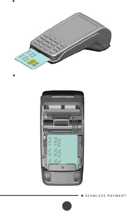
Card reader: insert the card horizontally with the chip facing
upwards and leave in position throughout the transaction.
Smart card
2nd card reader (Optional): is located under terminal
trapdoor (on back of the terminal). Insert the card up side
down chip facing the terminal.
Move 5000
900017771 R11 000 07/0117
Copyright© 2017 Ingenico
All rights reserved
11
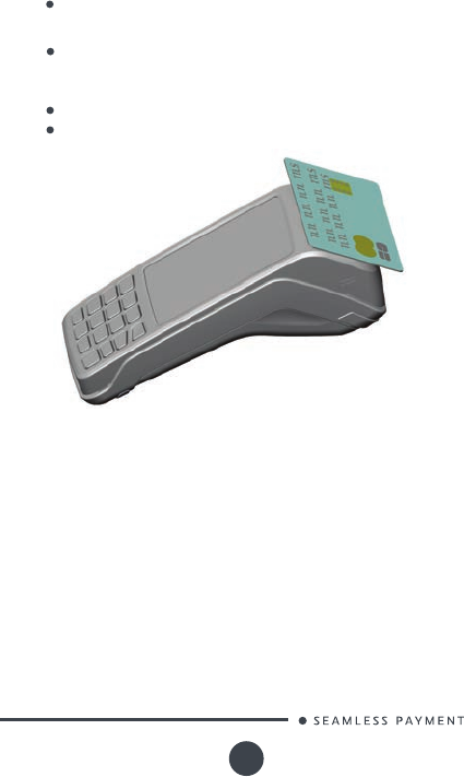
Bring the card rmly up to the active zone. Keep the card
close to the reader during the transaction
Contactless (optional)
The 4 virtual LEDs are displayed during the transaction.
The terminal behavior for the cardholder may depend on:
The terminal environment
Local usage (language…)
Move 5000
900017771 R11 000 07/0117
Copyright© 2017 Ingenico
All rights reserved
12
4_Installation
4_1 Recommendations
Location of the Move5000
Place the base on at surface near an electric socket and according
to the base to the telephone or a Ethernet socket. The terminal should
be placed far from any very hot zones, protected from vibrations,
dust, damp and electromagnetic radiation (computer screen, anti-theft
barrier etc.).
Operating conditions
Ambient temperature from +0°C to +50°C
Max relative humidity 85% at +40°C
Battery charging conditions
Ambient temperature from +0°C to +40°C
Storage conditions
Ambient temperature from -20°C to +55°C
Max relative humidity 85% at +55°C
Move 5000
900017771 R11 000 07/0117
Copyright© 2017 Ingenico
All rights reserved
13
4_2 USB Terminal connections
4_2_1 uUSB
There is an USB connector (microAB) on the left side of
the Move/5000 Wireless terminal (see below picture). This
connector manages Host and Slave connexions.
The terminal supports USB Keys with FAT16 or FAT32
The USB Key has to be used with an USB adapter (refers to
accessories section)
USB micro AB
Connector used for PC travel
charger, USB Key, etc…
*MicroAB connector durability: up to 10 000 mating cycles
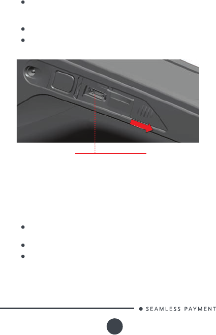
4_2_2 MicroSD memory Card
Insert the MicroSD Memory Card into the connector slot as
shown on the gure.
MicroSD connector is located on terminal side.
The terminal supports MicroSD up to 32GB

Move 5000
900017771 R11 000 07/0117
Copyright© 2017 Ingenico
All rights reserved
14
microSD connector
4_3 Opening trap door
CAUTION
Switch off the terminal before opening the trapdoor.
Turn the terminal and unclip the trapdoor by pushing on the
clip with as shown with the arrows on the picture
Move 5000
900017771 R11 000 07/0117
Copyright© 2017 Ingenico
All rights reserved
15
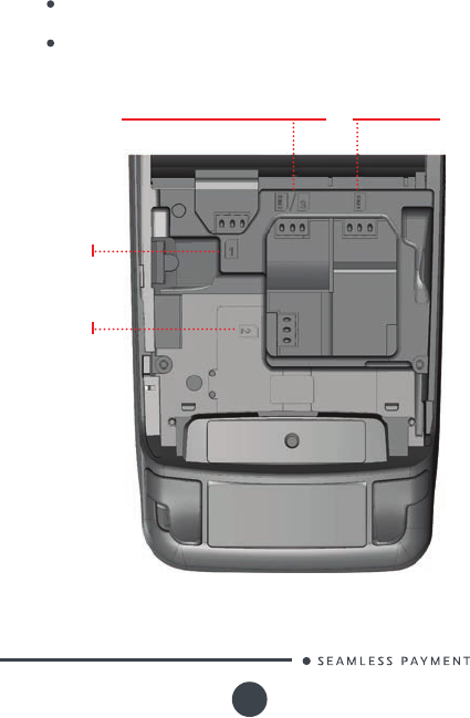
4_4 SAMs & SIMs
The connector modules security SAM/SIM are located inside the
terminal, in a closed compartment.
SAMs and SIMs are indentied by the engraved marks on the
lower housing
When introducing a SAM/SIM in its slot, be sure to put the cut
corner as indicated on the engraved marks
SIM 2 Connector (Dual SIM terminals)
or SAM3 connector SIM 1 Connector
SIM 1 Connector
SIM 2 Connector
Move 5000
900017771 R11 000 07/0117
Copyright© 2017 Ingenico
All rights reserved
16
4_5 Battery
4_5_1 Main characteristics
Charge
(power supply-1.5A)
50% capacity in 1,5 h; full capacity
in 4 hours
Battery life
Characteristics Li-ion 2900 mAh
450 transactions in GPRS with
fully charged battery, printing and
backlit activated
Can remain powered ON up to
150 hours with connected GPRS
link and terminal in sleeping state
starting with fully charged battery
and without energy consumption
related to backlit or radio link
* The battery capacity depends on the model of terminal and its use
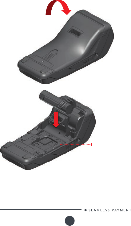
4_5_2 Installing the battery
WARNING
Check that the terminal is not connected to the main electric
network.
Turn your terminal and unclip the battery trapdoor by
pushing on the button as shown on the picture
Disengage the trapdoor
Take the battery pack included in the box
Locate the battery pack connector beside the battery
compartment
Plug the battery pack connector according to the
connector locating system and (as shown on picture).
Verify that it locks.
Place the battery pack in its compartment.
Close the battery compartment trapdoor.
Move 5000
900017771 R11 000 07/0117
Copyright© 2017 Ingenico
All rights reserved
17
Battery compartment

Move 5000
900017771 R11 000 07/0117
Copyright© 2017 Ingenico
All rights reserved
18
4_5_3 Charging the battery
When does the battery need to be charged?
On initial start up, charge the battery for 16 hours under the
environmental conditions stated above
When used daily, the terminal recharges its batteries each time it
is placed on its base . Charging is automatic
When used with a terminal power supply: connect the power
supply to Move5000 power connector.
How does the battery need to be charged?
The environment in which the charge takes place inuences
battery lifetime and autonomy (number of transactions)
The optimal conditions are as follows:
/ Charging away from any external heat source (radiator, sun,
enclosed area…)
/ The optimal temperature is between +15°C and +25°C
How can the battery be charged?
Using the base
Place the terminal on its base
Check if the battery symbol is ashing or moving (=battery
charging).
Using the terminal power supply (the terminal is out of its base)
Connect the terminal power supply unit to the terminal microAB
connector located on the left side of the terminal.
Connect the power supply unit to the power supply mains
network
Check to see if the battery symbol is ashing or moving(=battery
charging)
Move 5000
900017771 R11 000 07/0117
Copyright© 2017 Ingenico
All rights reserved
19
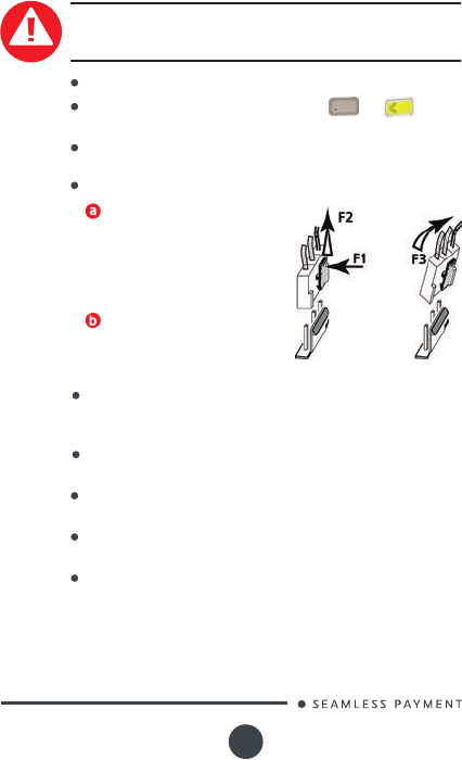
4_5_4 Changing the battery
It is imperative to use a battery authorized by Ingenico.
There is danger of explosion if battery used is not approved
by Ingenico.
Remove the terminal from its base
Turn it off by pressing simultaneously and (yellow
key) for about one second
Remove the battery trapdoor (see section 4.5.2“installing
battery”)
Carefully disconnect battery, following the instructions below.
Unlock the connector by
pressing the locking mechanism
as indicated by F1 arrow while
pulling this connector (F2 arrow ).
Release traction on it as soon as
the connector comes unclipped
Finish extracting connector
by tilting it slightly (F3 arrow)
to bring it away from the
terminal housing
Inform the terminal that battery will be replaced (*). Do so
start the terminal without battery by tting it on its base,
or connecting terminal power supply.
Remove terminal from base or disconnect terminal power
supply
Connect and install the new battery by following the
instructions in section 4.5.2 “Installing battery”
Close the battery trapdoor and charge the new battery.
See section «0 “Charging the Battery»
In order to preserve the environnement, dispose used
battery in compliance with current country recycling
legislation.
(*)The terminal memorizes that there is no battery simply by powering
up. It will then correctly perform-full recharge with the next battery.
Move 5000
900017771 R11 000 07/0117
Copyright© 2017 Ingenico
All rights reserved
20
4_6 Paper roll
4_6_1 Mains characteristics of INGENICO
paper roll
Colour White
Width
R40 paper roll Characteristics Precisions
Depending on IWL model two paper roll can be used:
58 mm
Diameter 40 mm
Length About 18 metres
The thermal paper can be deteriorated by poor storage
conditions, so we recommend you to avoid:
/ storage in hot wet places (near air-conditioner, humidity
higher than 85%)
/ exposure to sunlight or ultraviolet for long periods
/ contact with organic solvents (solvent type adhesive)
/ direct contact with materials containing plasticizers (PVC
transparent folders or envelopes)
/ direct contact with «diazo» papers
/ direct contact with water
/ Rubbing or pressing the paper too strongly
WARNING
For best product performance, only use heat sensitized
paper approved by Ingenico.
WARNING
Switch off the terminal prior to installing a paper roll.
Use only paper approved by Ingenico.
The use of non approved paper is likely to damage the
printer of your terminal.
Move 5000
900017771 R11 000 07/0117
Copyright© 2017 Ingenico
All rights reserved
21
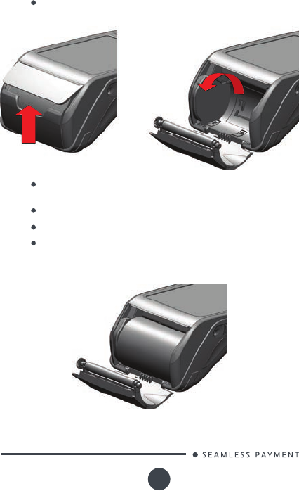
4_6_2 Installing paper roll
Open the paper compartment by lifting the catch located at
the rear of the terminal and pull the cover to the rear of the
terminal.
Insert the paper roll in the compartment following the
directions shown on the below picture
Pull the paper up to the top of the terminal
Maintain the paper and close the lid
Press simultaneously on both upper corners of the paper
ap, as shown by arrows on picture, until it clips into position
Move 5000
900017771 R11 000 07/0117
Copyright© 2017 Ingenico
All rights reserved
22
ADVICE
If you insert a new R40 paper roll, tear off the rst length
(one complete turn to avoid printing on adhesive tape
footprint).
5_Recommendations
5_1 Safety
Disconnect the Move/5000 power supply block adapter from
the electrical mains network.
Powering down the Move/5000 :
The Move/5000 is tted with an internal lithium cell which can
only be accessed by a qualied technician.
Lithium cell
Move5000 is tted with battery specially designed for this
terminal.
Battery
Only use the appropriate chargers and batteries listed in the
Ingenico’s catalogue.
Do not short-circuit the battery.
Do not attempt to open the battery container.
Used batteries must be disposed of at the appropriates sites.
WARNING
There is a risk of explosion if the battery is incorrectly re-
placed or is placed in a re.
The electrical outlet must meet the following criteria :
Electrical power outlet
Must be installed near the equipment and easily accessible;
Do not short-circuit the battery.
Do not attempt to open the battery container.
Used batteries must be disposed of at the appropriates sites.

Move 5000
900017771 R11 000 07/0117
Copyright© 2017 Ingenico
All rights reserved
23
The trapdoor for battery, SAM1/SAM2/SIM1/(SAM3/SIM2),
readers located underneath the terminal, must be in place during
the normal operation of the terminal. See sections «Removal of
SAM1/SAM2/SIM, modules» as well as «Connecting the battery».
SAM1/SAM2/SIM1/(SAM3/SIM2) readers compartment
Your handset must be switched off by removing the battery pack.
Remove the battery from the terminal when on an airplane.
Non-compliance with these safety rules may result in legal action
and/or a ban on later access to cellular network services.
On airplanes
Certain regulations restrict the use of radio equipment in chemical
plants, fuel depots and any site where blasting is carried out. You
are urged to comply with these regulations. The terminal shall be
protected by a specially tted and certied cover enabling use in
proximity to a fuel pump.
Explosion areas
Your handset is a radio transmitter which may interfere with
health appliances, such as hearing aids, pacemaker, hospital
equipment, etc.
Your doctor or the equipment manufacturer will be able to
provide you with appropriate advice.
Electronic health appliances
5_2 Security of your terminal
Your device fulls current applicable PCI PTS security requirements.
Upon receipt of your terminal you should check for signs of tampering
of the equipment. It is strongly advised that these checks are
performed regularly after receipt. You should check, for example: that
the keypad is rmly in place; that there is no evidence of unusual wires
that have been connected to any ports on your terminal or associated
equipment, the chip card reader or any other part of your terminal.
Such checks would provide warning of any unauthorised modications
to your terminal, and other suspicious behaviour of individuals that
have access to your terminal. Your terminal detects any “tampered
state”. In this state the terminal will repeatedly ash the message” Alert
Irruption!” and further use of the terminal will not be possible. If you
observe the “Alert Irruption!” message, you should contact the terminal
helpdesk immediately.
You are strongly advised to ensure that privileged access to your
terminal is only granted to staff that have been independently veried
as being trustworthy.
The terminal must never be put in or left at a location where it could be
stolen or replaced by another device.
Move 5000
900017771 R11 000 07/0117
Copyright© 2017 Ingenico
All rights reserved
24
CAUTION
Positioning of the terminal on check stand must be in such a
way to make cardholder PIN (Personal Identication Number)
spying infeasible.
Installing device on an adjustable stand must be in such a
way that consumers can swivel the terminal sideways and/
or tilt it forwards/backwards to a position that makes visual
observation of the PIN-entry process difcult.
Positioning of in-store security cameras such that the PIN-
entry keypad is not visible.
NEVER ask the customer to divulge their PIN Code. Customers
should be advised to ensure that they are not being overloo-
ked when entering their PIN Code.
5_3 Fixed installation
If the device is to be used in a situation where it is not possible for
the cardholder to pick up and shield their PIN entry themselves, the
device may be used without PIN shield, but it must be installed in the
following manner:
a) The device must be angled at 45 or more, so that oversight of the PIN
entry from the rear of the device is not possible.
b) The device must either be tted in a swivel stand – so that the
customer can position the device in the best angle to prevent oversight
– or the device must be xed in the best possible position to prevent
oversight if such a generic position exists in the specic environment
to which the device is installed.
c) The device environment must be accompanied with conspicuous
notices and educational material which informs the customer to shield
their PIN during PIN entry.
d) The device must be deployed so that oversight from other
customers, either in different payment lanes, or in other areas of
the shopping environment, is prevented. This may be achieved
through the placement of the lanes and device, so that the customer
is automatically positioned between the device keypad and other
customers. Alternatively, it may be achieved by the environment in
which the device is installed, so that the checkout itself shields the PIN
entry process.
e) The terminal is exclusively made for indoor use.
If the above conditions are not fullled, the device with PIN shield must
be used.
Move 5000
900017771 R11 000 07/0117
Copyright© 2017 Ingenico
All rights reserved
25
6_Standards
6_1 Environment (WEEE, Batteries and
Packaging)
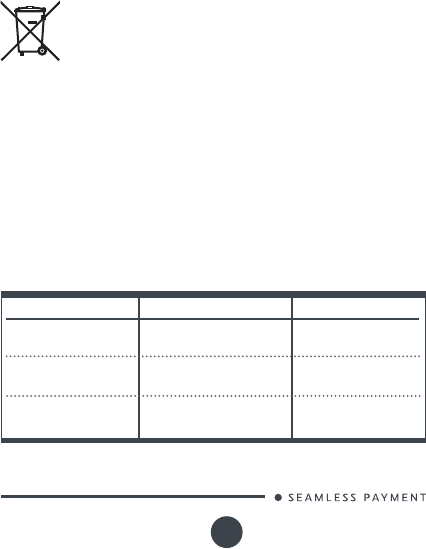
This product is labeled in accordance with European Directives
2002/96/EC concerning Waste Electrical and Electronic Equipment
(WEEE) and 2006/66/EC concerning Batteries and Accumulators. Those
provisions are requiring producers and manufacturers to become liable
for take-back, treatment and recycling upon end of life of equipment
and batteries.
The associated symbol means that WEEE and waste
batteries must not be thrown away but collected
separately and recycled.
Ingenico ensures that efcient collection and recycling schemes are
set-up for WEEE and batteries according to the local regulation of your
country. Please contact your retailers for more detailed information
about the compliance solution in place for disposing of your old
product and used batteries.
Packaging waste must also be collected separately to assure a proper
disposal and recycling.
Please note that proper recycling of the electrical and electronic
equipment and waste batteries will ensure safety of human health and
environment.
6_2 FCC/IC Compliance
Model Name
Product : Move/5000
CL/3G/WiFi/BT
FCC ID IC NUMBER
Product : Move/3500
CL/3G/WiFi/BT
Product : Move/5000
CL/WiFi/BT
3GWIBT
FCC ID : XKB-M5000CL
FCC ID : XKB-M5000
CLWIBT
IC ID : 2586D-
M50CL3GWIBT
IC ID : 2586D-
M50CL3GWIBT
IC ID : 2586D-M50
CLWIBT
FCC ID : XKB-M5000CL
3GWIBT
Move 5000
900017771 R11 000 07/0117
Copyright© 2017 Ingenico
All rights reserved
26
Model Name
Product : Move/3500
CL/WiFi/BT
FCC ID IC NUMBER
Product : Move/Base
Eth/Mod/BT
FCC ID : XKB-
M5000CLWIBT
IC ID : 2586D-
M50CLWIBT
This equipment has been tested and found to comply with the limits
for a Class B digital device, pursuant to part 15 of the FCC Rules.
These limits are designed to provide reasonable protection against
harmful interference in a residential installation. This equipment
generates, uses and can radiate radio frequency energy and, if not
installed and used in accordance with the instruction, may cause
harmful interference to radio communications.
However, there is no guarantee that interference will not
occur in a particular installation. If this equipment does cause
harmful interference to radio or television reception which can
be determined by turning the equipment off and on, the user is
encouraged to try to correct interference by one or more of the
following measures :
Reorient or relocate the receiving antenna.
Increase the separation between the equipment and
receiver.
Connect the equipment into an outlet on circuit different
from that to which the receiver is connected.
Consult the dealer or an experienced radio/TV technician
for help.
This device complies with Part 15 of the FCC Rules and Industry
Canada license-exempt RSS standard(s). Operation is subject to the
following two conditions:
(1) This device may not cause harmful interference, and
(2) This device must accept any interference received,
including interference that may cause undesired operation.
Le présent appareil est conforme aux CNR d’Industrie Canada
applicables aux appareils radio exempts de licence. L’exploitation
est autorisée aux deux conditions suivantes :
(1) l’appareil ne doit pas produire de brouillage, et
(2) l’utilisateur de l’appareil doit accepter tout brouillage
radioélectrique subi, même si le brouillage est susceptible
d’en compromettre le fonctionnement.
FCC ID : XKB-BASE
5000BT
IC ID : 2586D-BASE
5000BT
You are cautioned that changes or modications not expressly
approved by the part responsible for compliance could void the
user’s authority to operate the equipment.

Move 5000
900017771 R11 000 07/0117
Copyright© 2017 Ingenico
All rights reserved
27
Under Industry Canada regulations, this radio transmitter may
only operate using an antenna of a type and maximum (or lesser)
gain approved for the transmitter by Industry Canada. To reduce
potential radio interference to other users, the antenna type and
its gain should be so chosen that the equivalent isotropically
radiated power (e.i.r.p.) is not more than that necessary for
successful communication.
Conformément à la réglementation d’Industrie Canada, le présent
émetteur radio peut fonctionner avec une antenne d’un type et
d’un gain maximal (ou inférieur) approuvé pour l’émetteur par
Industrie Canada. Dans le but de réduire les risques de brouillage
radioélectrique à l’intention des autres utilisateurs, il faut
choisir le type d’antenne et son gain de sorte que la puissance
isotrope rayonnée équivalente (p.i.r.e.) ne dépasse pas l’intensité
nécessaire à l’établissement d’une communication satisfaisante.
No changes shall be made to the equipment without the
permission of Ingenico as this may void the user’s authority to
operate the equipment.
Tout changement apporté à ce terminal non expressément
approuvé par Ingenico est susceptible d’annuler le droit de
l’utilisateur à se servir de cet équipement.
This product meets the applicable Innovation, Science and
Economic Development Canada technical specifications. The
Ringer Equivalence Number (REN) indicates the maximum
number of devices allowed to be connected to a telephone
interface. The termination of an interface may consist of any
combination of devices subject only to the requirement that the
sum of the RENs of all the devices not exceed five. REN for this
device is 0.1.
Move 5000
900017771 R11 000 07/0117
Copyright© 2017 Ingenico
All rights reserved
28
Le présent appareil est conforme aux spécications techniques
applicables d’Innovation, Sciences et Développement
économique Canada. L’indice d’équivalence de la sonnerie (IES)
sert à indiquer le nombre maximal de dispositifs qui peuvent être
raccordés à une interface téléphonique. La terminaison d’une
interface peut consister en une combinaison quelconque de
dispositifs, à la seule condition que la somme des IES de tous les
dispositifs n’excède pas cinq. L’IES pour cet appareil est de 0.1.
The device for operation in the band 5150–5250 MHz is only for
indoor use to reduce the potential for harmful interference to co-
channel mobile satellite systems. In addition, high-power radars
are allocated as primary users (i.e. priority users) of the bands
5250–5350 MHz and 5650–5850 MHz and that these radars
could cause interference and/or damage to LE-LAN devices.
Les dispositifs fonctionnant dans la bande de 5 150 à 5 250 MHz
sont réservés uniquement pour une utilisation à l’intérieur an
de réduire les risques de brouillage préjudiciable aux
systèmes de satellites mobiles utilisant les mêmes canaux.
D’autre part, les utilisateurs de radars de haute puissance sont
désignés utilisateurs principaux (c.-à-d., qu’ils ont la priorité) des
bandes de 5250 à 5350 MHz et de 5650 à 5850 MHz et, d’autre
part, que ces radars pourraient causer du brouillage et/ou des
dommages aux dispositifs de RL-EL.
Part 68 of FCC Rules
Model Name
Product : Move/Base Eth/Mod/BT
US MODEM
US : IEOMM01BM5000
This equipment complies with Part 68 of the FCC rules and the
requirements adopted by the ACTA. On the bottom of this equipment
is a label that contains, among other information, a product identier
in the format US : AAAEQ##TXXXX. If requested, this number must be
provided to the telephone company.
This equipment uses the following USOC jacks : (RJ11C).
A plug and jack used to connect this equipment to the premises wiring
and telephone network must comply with the applicable FCC Part 68
rules and requirements adopted by the ACTA. A compliant telephone
cord and modular plug is provided with this product. It is designed to
be connected to a compatible modular jack that is also compliant. See
installation instructions for details.

Move 5000
900017771 R11 000 07/0117
Copyright© 2017 Ingenico
All rights reserved
29
The REN is used to determine the number of devices that may be
connected to a telephone line. Excessive RENs on a telephone line may
result in the devices not ringing in response to an incoming call. In most
but not all areas, the sum of RENs should not exceed ve (5.0). To be
certain of the number of devices that may be connected to a line, as
determined by the total RENs, contact the local telephone company.
If this equipment causes harm to the telephone network, the telephone
company will notify you in advance that temporary discontinuance
of service may be required. If advance notice is not practical, the
telephone company will notify the customer as soon as possible.
Also, you will be advised of your right to le a complaint with the FCC
if you believe it is necessary.
The telephone company may make changes in its facilities, equipment,
operations, or procedures that could affect the operation of this
equipment. If this happens, the telephone company will provide
advance notice in order for you to make the necessary modications to
maintain uninterrupted service.
If trouble is experienced with this equipment, please contact INGENICO,
or your local INGENICO distributor or service center in the U.S.A. for
repair and/or warrant information.
If your home has specially wired alarm equipment connected to the
telephone line, ensure the installation of this equipment does not
disable your alarm equipment. If you have questions about what
will disable alarm equipment, consult your telephone company or a
qualied installer.
U.S.A service center:
Ingenico North America
3025 Windward Plaza, suite 600
Alpharetta, GA 30005
USA
Tel: +1(678) 456 1200
Fax: +1 (678) 456 1201
Email: info.us@ingenico.com
Move 5000
900017771 R11 000 07/0117
Copyright© 2017 Ingenico
All rights reserved
30
7_Troubleshooting
The terminal does not turn on
Check the battery ( is it discharged ?, is it connected ?)
A full discharged battery can take long charging
time to recover
Connect terminal to terminal power supply or put it on powered
base
Cards are not read
Check that the magnetic card is swiped correctly (with
magnetic band on terminal side).
Swipe again the card with the magnetic stripe movement
constant and rapid
Verify that the magnetic strip is not damaged, grooved or
cracked
Make sure you have inserted correctly the smart card into
the smart card reader and removed the card only after the
transaction is performed.
The ticket is not printed
Check the presence and proper positioning of the paper roll.
Possibly adjust the paper roll following the instructions in this
manual (section 0 “Installing the paper roll”)
Check the type of paper used (thermal paper must be used)
Verify thermal paper sensitive side.

Move 5000
900017771 R11 000 07/0117
Copyright© 2017 Ingenico
All rights reserved
www.ingenico.com
28-32, boulevard de Grenelle, 75015 Paris - France / (T) +33 (0)1 58 01 80 00 / (F) +33 (0)1 58 01 91 35
Ingenico - SA au capital de 47 656 332 / 317 218 758 RCS Nanterre
31
“This Document is Copyright © 2017 by INGENICO Group. INGENICO
retains full copyright ownership, rights and protection in all material
contained in this document. The recipient can receive this document
on the condition that he will keep the document condential and will
not use its contents in any form or by any means, except as agreed
beforehand, without the prior written permission of INGENICO.
Moreover, nobody is authorized to place this document at the disposal
of any third party without the prior written permission of INGENICO.
If such permission is granted, it will be subject to the condition that
the recipient ensures that any other recipient of this document, or
information contained therein, is held responsible to INGENICO for the
condentiality of that information.
Care has been taken to ensure that the content of this document is
as accurate as possible. INGENICO however declines any responsibility
for inaccurate, incomplete or outdated information. The contents of
this document may change from time to time without prior notice, and
do not create, specify, modify or replace any new or prior contractual
obligations agreed upon in writing between INGENICO and the user.
INGENICO is not responsible for any use of this device, which would be
non consistent with the present document.
All trademarks used in this document remain the property of their
rightful owners.”
Your contact