Ingenico ML30CL Card Reader User Manual 9000001931 R11 000 05
INGENICO Card Reader 9000001931 R11 000 05
Ingenico >
User Manual
Passage des câbles :
Pour passer le câble, il peut être nécessaire de le déconnecter. Procéder selon les dessins suivants :
Retrait et mise en place du câble
Figure 1
Figure 2
Figure 3
Pour retirer le câble :
•
Appuyer sur la languette de verrouillage indiquée par la flèche figure 1,
•
Tirer sur le connecteur figure 2,
•
Dégager le passe fil en le glissant selon la flèche figure 3.
Pour mettre en place le câble procéder dans l'ordre inverse.
Passage du câble
Remarque : Prévoir une longueur de câble suffisante dans le socle afin de pouvoir
retirer le terminal du socle et atteindre les connecteurs
Le câble série peut passer sous le socle pour rejoindre une ouverture. Soit dans le
volume de la rainure 3, soit en face des ouvertures 1 ou 2. (cf. figure ci-contre)
Prévoir une ouverture de diamètre 18mm dans le bureau ou le présentoir pour le
passage du connecteur plug coudé. (14mm si l’épaisseur du bureau ou du présentoir
est inférieure à 4mm)
Particularité du câble Ethernet :
Passage du câble Découpage de la trappe
Le câble Ethernet est standard et n’est pas
fourni. Il nécessite l'utilisation du socle.
L'ouverture dans le bureau ou le présentoir doit
être en regard du repère 2.
Prévoir une ouverture de diamètre 14 mm. Le
terminal peut être monté avec ou sans trappe.
Prévoir une ouverture de diamètre 14 mm dans
le bureau ou le présentoir.
Si la trappe est
montée, il faut la
découper en (4) pour
faire passer le câble
Ethernet.
Sécurité de votre terminal
Dès réception de votre terminal, il est fortement recommandé de procéder à la vérification de l’état de votre équipement. Vous devait
vérifier par exemple : que le clavier est bien en place, qu’aucun fils ne soit déconnectés des ports du terminal ou des périphériques,
vérifier également le lecteur de carte à puce , ou toute autre partie de votre terminal. Ce contrôle permet de signaler toute modification
inhabituelle sur votre équipement, et le comportement suspect d'autres personnes qui ont accès à votre terminal. Votre terminal détecte
un Etat "trafiqués». Dans ce cas, votre terminal émet en clignotement le message « Alerte Irruption » et son utilisation ultérieure n’est pas
possible. Si vous observez le message “Alert Irruption!”, vous devez immédiatement contacter votre service d’assistance. Vous devez
vous assurer que votre terminal est un accès à du personnel qualifié et digne de confiance.
Fin de vie du produit
Le produit fait parti de la catégorie des équipements électriques et électroniques. A ce titre, il est soumis à la
Directive DEEE qui impose la collecte et le recyclage des équipements en fin de vie. Les équipements Ingenico
portent les indications exigées par la directive DEEE. Ainsi, ce symbole apposé sur le produit indique qu’il fait l’objet
d’une collecte sélective et ne doit pas être éliminé avec les autres déchets ménagers ou commerciaux. Afin
d’assurer que le produit soit collecté et recyclé dans le respect de l’environnement, vous devez contacter votre
fournisseur qui vous donnera la marche à suivre (à défaut, adressez-vous au siège commercial Ingenico qui couvre
votre zone locale en vous rendant sur le site internet www.ingenico.com, rubrique « contactez-nous »). L’élimination incontrôlée des
déchets peut porter préjudice à l’environnement et à la santé humaine. Ainsi, en recyclant de façon responsable votre produit, vous
contribuez à la préservation des ressources naturelles et à la protection de la santé humaine.
ML30 installation manual
Safety instructions:
• Lithium battery : ML30 equipment is equipped with a lithium battery that is non-accessible for the user. Only a
qualified operator is authorized to open the unit and to replace this component.
• Power supply network : For cutting the power supply to the ML30, disconnect the power adapter from the power
supply network. You should provide a socket for the incoming power supply satisfying the following points:
• Socket installed near the equipment and easy to access
• Socket meeting the standards and regulations in force in the country of use
For Pluggable Equipment Type A, the protection in the installation is assumed to be 20A.
• Ethernet connection : the Ethernet link is for use indoor only. The link is a SELV circuit (Save Extra Low Voltage)
according to standard EN60950.
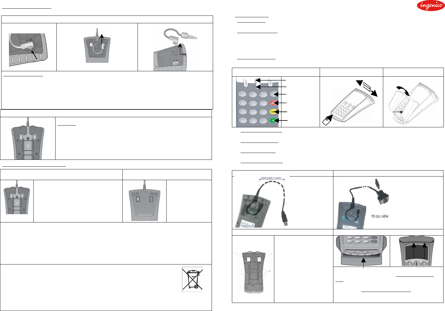
Keypad
Inserting and sliding the cards Installing the private shield
UP Arrow key
Down Arrow
Key
Function Key
Cancel Key
Delete Key
Enter Key
( option )
Physical characteristics: Weight (without cable) about 240g
Dimensions 165 x 95 max. x 45mm (lxWxH)
Operating conditions: Temperature +5°C to +40°C
Maximum relative humidity 85% RH at +55°C
Storage conditions: Temperature -20°C to +55°C
Maximum relative humidity 85% RH at +55°C
Maximum consumption: 280mA at +8V, 350mA at +5V
USB cable (2m straight) - 252 292 872 RS232 cable (3m straight) - 252678837 + Power supply
USB2.0 - full speed
(12Mbps max.)
USB slave
1 : 5 volts
2 : D-
3 : D+
4 : GND
USB type A plug
DCE type – SUBD9
(115Kbps max.)
2 : TX
3 : RX
5 : GND
PSU US plug - 179901469
• 120VAC - 50Hz / 60Hz
• 8VDC / 2A
Fixing of the stand adapter Maintain the product on its base
Three screws can fix the base.
Two choices are possible, the 3
holes (a) or the 3 holes (b)
indicated on the drawing
opposite. The base can be
used as gauges of pointing on
the holes of the screws and for
the openings of connectors.
A notch situated on its front side and two clips on the
backside maintains the terminal. To install it on the
base, first introduce the front side of the terminal and
then, make a press on its backside until hearing the
locking noise. To remove it from the base, remove the
two clips one after the other while pulling up the
equipment
295008514AE 9000001931 R11 000 05/1009
INGENICO – 192 avenue Charles de Gaulle – 92200 Neuilly sur Seine – France Copyright © 2010 Ingenico
Tél. 33(0)1 46 25 82 00 - Fax 33 (0)1 47 72 56 95 All rights reserved
a
b
*295008514AE
Cabling
:
For cabling, it must be necessary to disconnect the cable from the terminal. Proceed as follow :
Dismounting and mounting the cable from the terminal
Press the locking device
Hang on the connector
Push on the feed
through and dismount
it
Installing the cable
Note: Take care to have sufficient available length of cable in order to remove the
terminal from its base and to unplug the connector.
The serial cable can go under the base to reach the opening.
Maybe by the way mentioned as (3), or right in front of the connectors mentioned as (1).
Make an 18 mm diameter hole in the base in order to have a path for the squared angle
connector. (14mm diameter is sufficient in case of base thickness lower than 4 mm)
Ethernet cable particularity :
Ethernet Cable Preparing the back cable cover
The Ethernet cable is standard and not
included.
The use of Ethernet connection impose the
use of the base.
The path is through a hole in the desk or the
tray in front of (2).
The back casing can be mounted or not.
The hole in the desk or the tray must be 14mm
diameter
If the back cover is
mounted, it must be
opened with a knife or a
screwdriver (area
mentioned as 4) in order
to have a path for the
Ethernet cable.
FCC ID : XKB-ML30 – XKB-ML30CL
This equipment has been tested and found to comply with the limits for a Class B digital device, pursuant to part 15 of the FCC Rules.
These limits are designed to provide reasonable protection against harmful interface in a residential installation. This equipment
generates uses and can radiate radio frequency energy and, if not installed and used in accordance with instruction, may cause harmful
interference to radio communications. However, there is no guarantee that interference will not occur in a particular installation. If this
equipment does cause harmful interference to radio or television reception which can be determined by turning the equipment off and
on, the user is encouraged to try to correct interface by one or more of the following measures :
• Reorient or relocate the receiving antenna.
• Increase the separation between the equipment and receiver.
• Connect the equipment into a outlet on circuit different from that to which the receiver is connected.
• Consult the dealer or an experience radio/TV technician for help.
CAUTION
:
The user is cautioned that any changes or modification not approved by INGENICO could void user’s authority to operate the
equipment
Security of your terminal
Upon receipt of your terminal you should check for signs of tampering of the equipment. It is strongly advised that these checks are
performed regularly after receipt. You should check, for example: that the keypad is firmly in place; that there is no evidence of unusual
wires that have been connected to any ports on your terminal or associated equipment, the chip card reader, or any other part of your
terminal. Such checks would provide warning of any unauthorised modifications to your terminal, and other suspicious behaviour of
individuals that have access to your terminal. Your terminal detects any “tampered state”. In this state the terminal will repeatedly flash
the message” Alert Irruption!” and further use of the terminal will not be possible. If you observe the “Alert Irruption!” message, you
should contact the terminal helpdesk immediately. You are strongly advised to ensure that privileged access to your terminal is only
granted to staff that have been independently verified as being trustworthy.
End-of-life
-
The product belongs to the family of electrical and electronic equipment. Therefore, it is subjected to the WEEE
directive which requires the collection and the recycling at the end of life product. The Ingenico products present the
symbol for the marking of electrical and electronic equipment as required by the WEEE Directive. The crossed-out
wheeled bin printed on the product gives the information about the requirement not to dispose of WEEE as unsorted
municipal waste and to collect such WEEE separately. To assure that the product is collected and recycled with respect to the
environment, you must contact your supplier (in defect, contact the Ingenico local office or the commercial head office in charge of your
country on www.ingenico.com, « contact us » page). The abandonment or uncontrolled disposal of waste can cause harm to
environment and to human health. So, by recycling your product in a responsible manner, you contribute to the preservation of natural
resources and to the protection of human health.
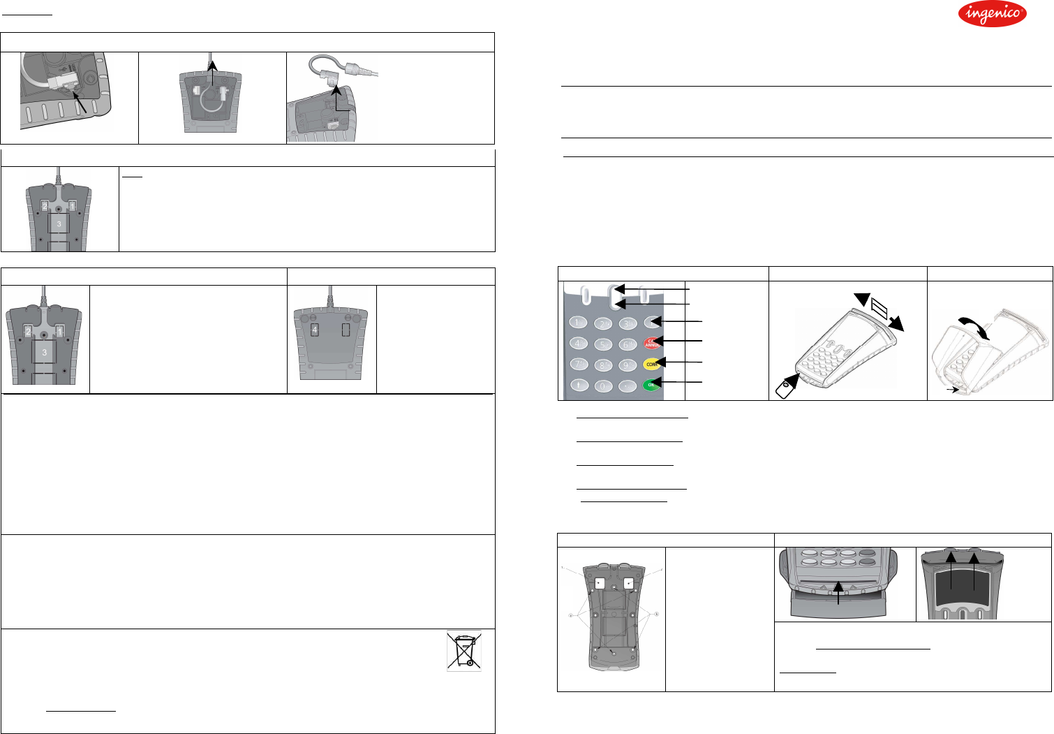
Description des touches
Sens d'introduction des cartes
Montage cache code
Flèche haut
Flèche bas
Fonction
Abandon
Correction
Validation
Option
Caractéristiques physiques : Masse (sans câble) Environ 240g
Dimensions 165 x 95 max x 45mm (lxWxH)
Conditions d'exploitation : Température +5°C à +40°C
Humidité relative maximum 85% RH à +55°C
Conditions de stockage : Température -20°C à +55°C
Humidité relative maximum 85% RH à +55°C
Consommation maximum : 280 mA à +8V, 350 mA à +5V
Câbles débrochable : USB A ( 2m) - 252292872
RS232 SUBD9 (3m) - 252678837 + alimentation externe – 8VDC
NOTICE D’INSTALLATION DU ML30
Consignes de sécurité
:
• Pile au lithium : ML30 est muni d'une pile au lithium qui n'est pas accessible à l'opérateur. Seule une personne
informée et habilitée peut ouvrir l'appareil et intervenir sur ce composant.
• VORSICHT: ML30 ist mit einer Lithium-Batterie, die nicht zugänglich ist für den Benutzer ausgestattet. Der
Wiedereinbau der Batterien muß von qualifiziertem Personal bewirkt werden.
Beachten Sie die Polarität für die Batterie Lithium. Eine fehlerhafte Installation der Batterie kann eine Explosion
führen. Entsorgen Sie die Batterien entsprechend den Anweisungen des Herstellers
• Caution : For Switzerland, Annex 4.10 of SR 814.013 applies for batteries
• Alimentation par le secteur (option RS232) : Pour mettre le ML30 hors tension, déconnecter le bloc alimentation du
réseau électrique. Prévoir une prise d'arrivée du réseau d'alimentation électrique satisfaisant aux points suivants
• Prise installée à proximité du matériel et aisément accessible ;
• Prise répondant aux normes et réglementations en vigueur dans le pays d'utilisation ;
Pour un équipement avec prise Type A, la protection de l'installation doit être fixée à 20A.
• Raccordement au réseau Ethernet : Le réseau Ethernet doit rester interne au bâtiment. Cette liaison est un circuit
TBTS (Très Basse Tension de Sécurité) au sens de la norme EN60950.
fixation du socle Maintien du produit sur son socle
Le socle peut être fixé
par trois vis.
Deux choix sont
possibles, les trous (a)
ou (b).
Le socle peut être
utilisé comme gabarits
de pointage des trous
de vis et des ouvertures
de connecteurs.
ML30 est maintenu par une encoche à l'avant et deux clips à
l'arrière. Pour l'installer sur son socle, engager l'avant du
terminal et appuyer sur l'arrière jusqu'au "clac" de clipsage.
Pour l'enlever, écarter les clips l'un après l'autre en soulevant le
terminal à l'arrière.
295008514AE 9000001931 R11 000 05/1009
INGENICO – 192 avenue Charles de Gaulle – 92200 Neuilly sur Seine – France Copyright © 2010 Ingenico
Tél. 33(0)1 46 25 82 00 - Fax 33 (0)1 47 72 56 95 All rights reserved
*295008514AE
b
a