Ingenitech TMU1000 In-Vehicle Telematic Computer User Manual
Ingenitech (NZ) Ltd In-Vehicle Telematic Computer
User Manual
FINISH
• Refertothefull-installationguidebeforeusingthisquick
installationguide.Thefullinstallationguidecanbedownloaded
fromourwebsitewww.internationaltelematics.com.
• BeforeaSIMCardisinstalledorremovedfromtheibright™
X–SeriesUnit,the‘POWER’mustbedisconnectedotherwise
itmaycausedamagetothedeviceorSIM.
• AlwaysrefertotheVehicle’s‘Owner’sManual’beforestarting
installationofibright™units.Thepositionoftheibright™units
connectionsandcordsmustnotobstructthedriverorany
movingpartsofthevehicle.Wiringmustbeconnected
toacleannon-fusedterminalwithaconsistentvoltage
withintherangeof8to28voltsbyaprofessional.
• Checkallpartsaresupplied(refertofullinstallationtraining
guideforreference)beforecommencinginstallation.
PLEASE READ
BEFORE INSTALL
Quick Installation Guide
Provisioning On-Line or via Bluetooth PDA
Provisioningoftheibright™X–Seriescanbecompletedon-lineutilis-
ingtheinformationcapturedonthe‘InstallWorkReport’.Alternativelya
Bluetooth/Hand-helddevicethatisWindowsMobile5basedPocketPC
/PocketPCPhonewiththeibright™‘Provisioningsoftware’canbeused.
Forsecurityreasons,ibright™on-lineregistrationaccessandibright
ProvisioningWindowsMobile5Softwareisavailablefromyournearest
InternationalTelematicsoce.
ibright™ Synchronising with OBD
A.
Pressibright™X-SeriesandD-Series
SyncButtonsforaminimumof5seconds
eachwithin15secondsofeachother.
B.
AfterpressingbothSyncbuttonson
boththeXandD-Series,theunitswill
createasecurewirelessconnection
within40seconds.
Fill in Install Work Report
ENTER IBRIGHT ASSET DETAILS
BACK SELECT
1816
19
17
Pre-Installation
Installation
Registration and Provisioning
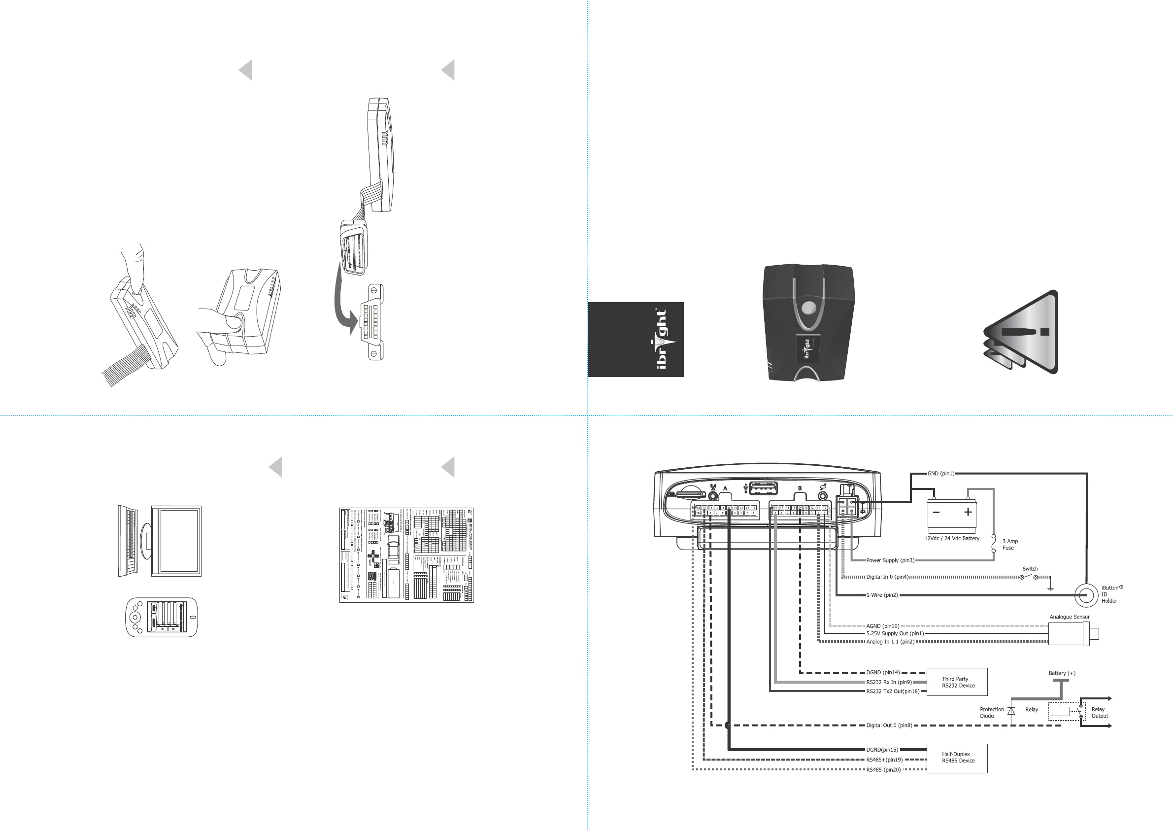
ibright™ Wiring Diagram
Registration and ProvisioningD- Series Installation
ibright™ Wiring Diagram
©2007InternationalTelematics
InternationalTelematicsProduct
QuickInstallGuideVersion1
VersionDate06July2007
www.internationaltelematics.com
ibright™ into OBD II Connection.
Connecttheibright™D-Seriestothe
vehiclesOBDIIPort.CheckLED’s,then
secureintoplacewitheasyaccesstothe
Syncbutton.
Tamper Sticker After SIM Install
LockthelidoftheX–SeriesbackinplaceafterSIMCard
hasbeeninstalledandusetheallocated‘TamperProof’
stickertosealthelidbeforecommencinginstallation.
Scope ibright™ X– Series Position
Thepositioningoftheibright™X–Seriesunitisimpera-
tivetoensuretheunitworkscorrectly.
Installtheunitinthevehicle,orientatedasperoneof
thesefouroptions;
Identify and Document Orientation and
where Unit is Installed.
Documentonthe‘INSTALLWORKREPORT’.
ibright™ X– Series Antennas
ibright™X–SerieshasinternalGPSandGPRSantennas.
Shouldplacementoftheibright™X–Serieshinderthe
receptionoftheinternalantennas,externalantennas
shouldbetted.Pleaserefertoibright™trainingguide
forspecicantennasandinstallationrequirements.
NOTE:Antennasshouldnotbeconnected
ordisconnectedwhilst‘POWER’ison.
1ExternalLights
2Electronics&Ignition
3InternalLights
4VehicleCondition
1ExternalLights
2Electronics&Ignition
3InternalLights
4VehicleCondition
Pre Vehicle Checks
InternationalTelematicsrecommendthatallinstallation
companiesandinstallersperformthoroughpreand
postvehicleelectronicchecks.Thisensuresinstallation
hasnoteectedtheworkingconditionofthevehicle.
Roof of vehicle Left hand side
of vehicle
Front
of vehicle
Right hand
side of vehicle
Rear of vehicle
Floor of vehicle
Optimum Position
Floor of Vehicle
16
2
7
3
8
4
9
5
10
11
12
13
14
15
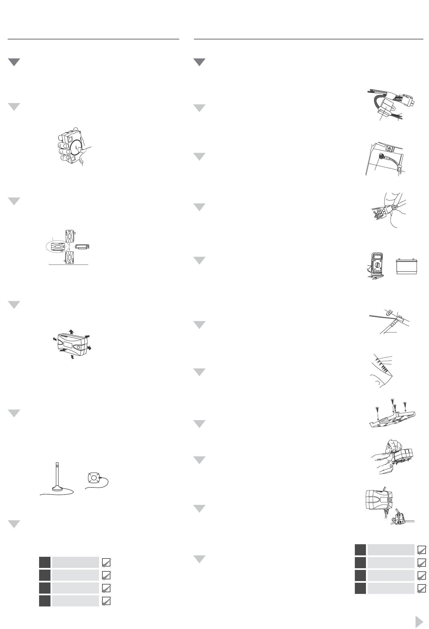
Power & Earth Wires
EnsureyouhavethecorrectPowerandEarth(Ground)wires
Connect Dedicated Earth
The‘EarthWire’shouldalwaysbeconnectedbeforethepower
wire.Securelyconnecttheearthwiretoa‘DedicatedEarthChas-
sisPoint’asillustratedhere.
Connect 4 Circuit Plug
Connectthe‘Power/Earth’4circuitplugintotheallocatedport.
Ensuretheconnection‘clicks’intoplaceandisalockedconnection.
Test for Continuous Voltage
Usingamulti-metertestallpowersuppliesbeforeconnecting
ibright™equipment.
Checkthatthepowerwirecanconnectdirectlytoapowerbaror
commonterminal.
ibright™hasaninternalbatteryvoltagemeterandaconnection
toasourcethatfeedsdirectlyfromthebatteryisrequired.
Connect Power Wire to Source
Connecttoacontinuous+12to+24voltDCbattery.Thenominated
powersourceshouldnothaveadropofmorethan0.5voltsbetween
themountingpoint&thebattery.
Connectthewiressecurely(ideallysolder).
Check LEDs for Unit Status
Checkthatthe‘Power’,’Networkconnection’,and
‘GPSConnection’aresolidlights.
A‘ashing’lightindicatestheunitistryingtoobtain
aconnection.
Connect Mounting Bracket
Screwonthebracketatanangleof90°asillustratedinFig.2
beforeattachingibright™X–Seriesunit.
Attach ibright Securely
Attachtheibright™unittothemountingbracket.
Useacable-tiearoundtheibright™unitandbracketfor
additionalsecurity.
Tamper Proof if required
Shouldtherebearequirementtotamperprooftheibright™unit,
usecablesties.
Post Vehicle Checks
InternationalTelematicsrecommendthatallinstallation
companiesandinstallersperformthoroughpreandpost
vehicleelectronicchecks.Thisensuresinstallationhasnot
eectedtheworkingconditionofthevehicle.
3.0 AMP
mini-blade fuse
Earth (ground)
Black Wire
Power (PWR)
Red Wire
Dedicated
‘Chasis Earth’
8-28 Volts DC
Solder connection
with Resin Core
Solder
Power Wire
Power (Solid Green)
Network (Solid Orange)
GPS (Solid Red)
Pre-Installation:
Scoping and Checking Steps
Installation:
Quick Guide Steps
Start
Registration and Provisioning
Federal Communications Commission Statement
DECLARATION OF CONFORMITY WITH FCC RULES FOR ELECTROMAGNETIC COM-
PATIBILITY
We,Ingenitech (NZ) Limited,of3A, 125 The Strand, Parnell, Auckland 1010, New Zealand,
declareunderoursoleresponsibilitythattheproduct,TMU1000 (ibright™ X-Series unit),towhich
thisdeclarationrelates,complieswithPart15oftheFCCRules.
Operationissubjecttothefollowingtwoconditions:
Thisdevicemaynotcauseharmfulinterference,and•
Thisdevicemustacceptanyinterferencereceived,includinginterferencethatmaycause•
undesiredoperation.
Caution: Exposure to Radio Frequency Radiation
TheradiatedoutputpoweroftheTMU1000iswellbelowtheFederalCommunicationsCommission
(FCC)radiofrequencyexposurelimits.Nevertheless,itisimportantthattheTMU1000isinstalledand
usedinsuchamannerthatthepotentialforhumancontactduringnormaloperationisminimized.
WhenconnectinganexternalantennatotheTMU1000,theantennashallbeplacedinsuchaman-
nertominimizethepotentialforhumancontactduringnormaloperation.Toavoidthepossibility
ofexceedingtheFCCRadiofrequencyexposurelimits,humanproximitytotheantennamustnot
belessthan20cm(8inches)duringnormaloperation.
Federal Communications Commission Notice
ThisequipmenthasbeentestedandfoundtocomplywiththelimitsforaClassBdigitaldevice,
pursuanttoPart15oftheFCCRules.Theselimitsaredesignedtoprovidereasonableprotection
againstharmfulinterferenceinatypicaleetassetinstallation.
Thisequipmentgenerates,uses,andcanradiateradiofrequencyenergyand,ifnotinstalledand
usedinaccordancewiththeinstructions,itmaycauseharmfulinterferencetoradioortelevision
communications.Thereisnoguaranteethatinterferencewillnotoccuratanyparticularinstallation.
IftheTMU1000doescauseharmfulinterferencetoradioortelevisioncommunications,whichcan
bedeterminedbyturningtheequipmentoandon,theuserisencouragedtotryandcorrectthe
interferencebyoneormoreofthefollowingmeasures:
Re-orientorrelocatetheradioortelevisiondevice’sreceivingantenna.•
IncreasethedistancebetweentheTMU1000andtheradioortelevisiondevice.•
ConnecttheTMU1000toapowersupplyonacircuitdierenttothecircuittowhichtheradio•
ortelevisiondeviceisconnected.
Consultthedealeroranexperiencedradio/TVtechnicianforhelp.•
Modications
TheFCCrequirestheusertobenotiedthatanychangesormodicationstothisdevicethatare
notexpresslyapprovedbyIngenitech(NZ)Limitedmayvoidtheuser’sauthoritytooperatethe
equipment.