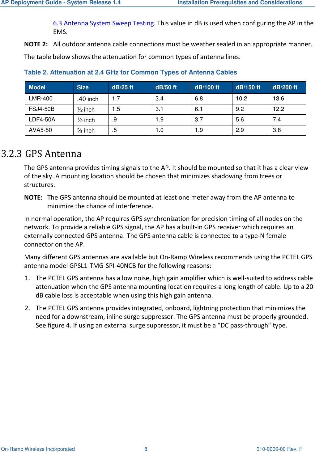
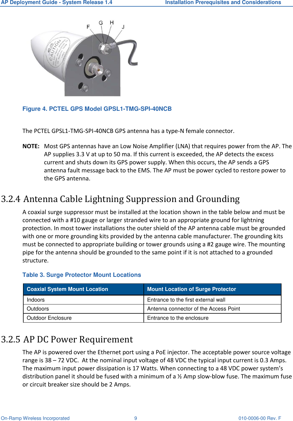
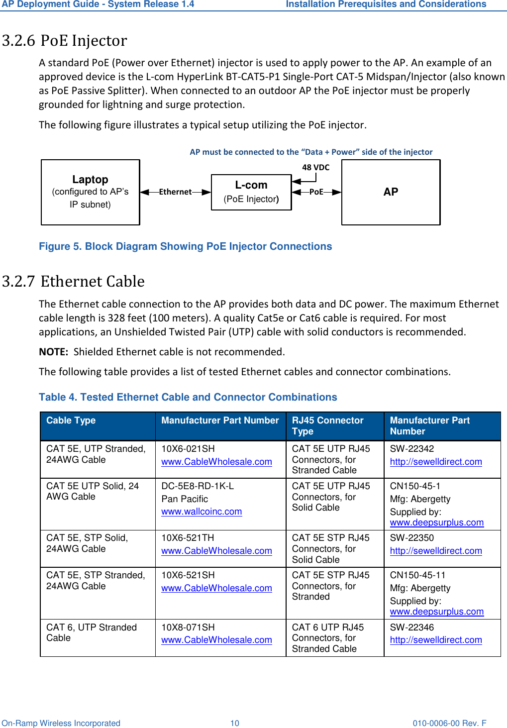
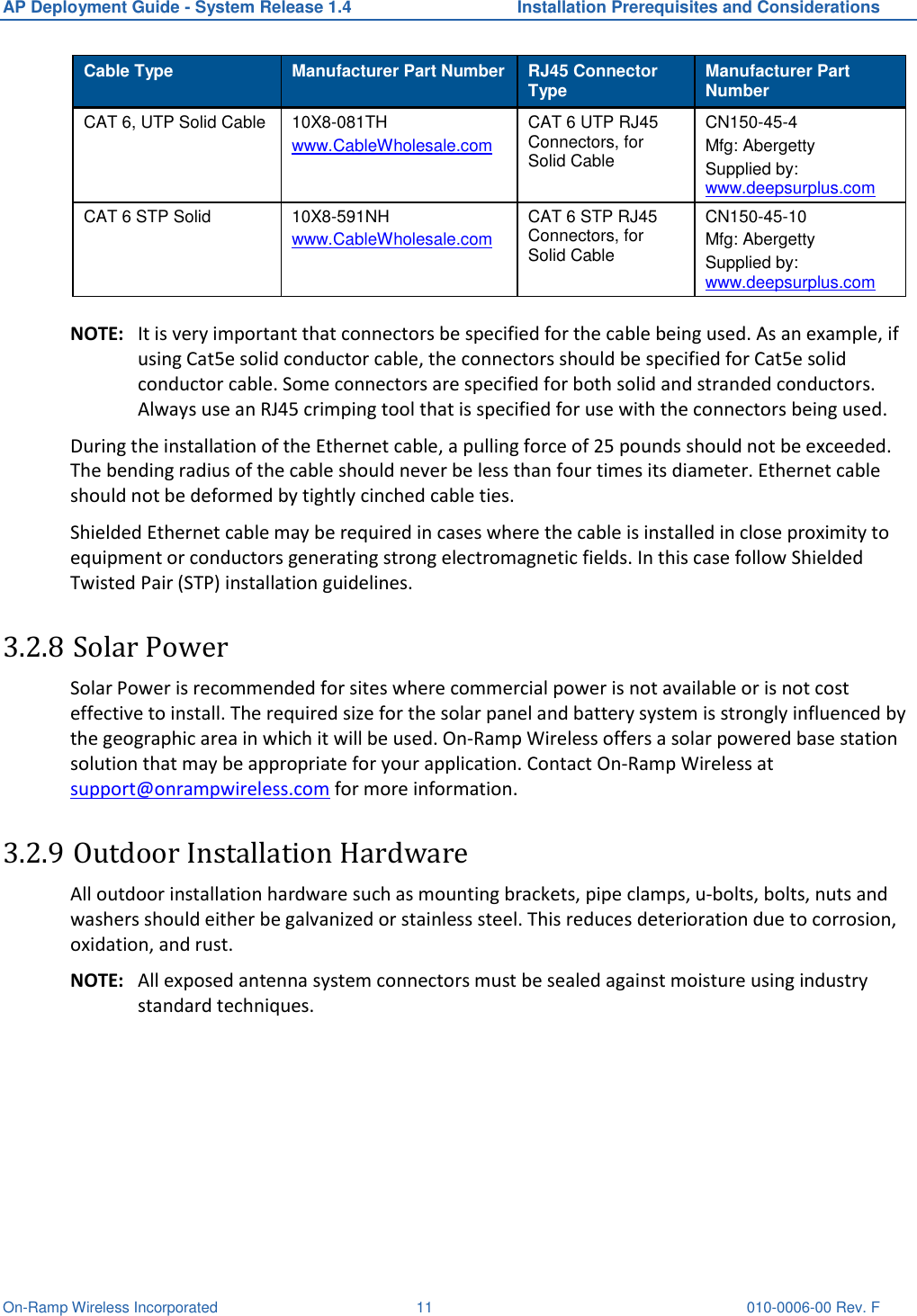
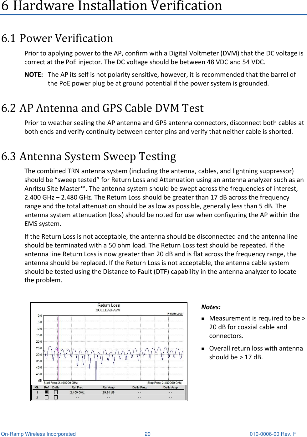
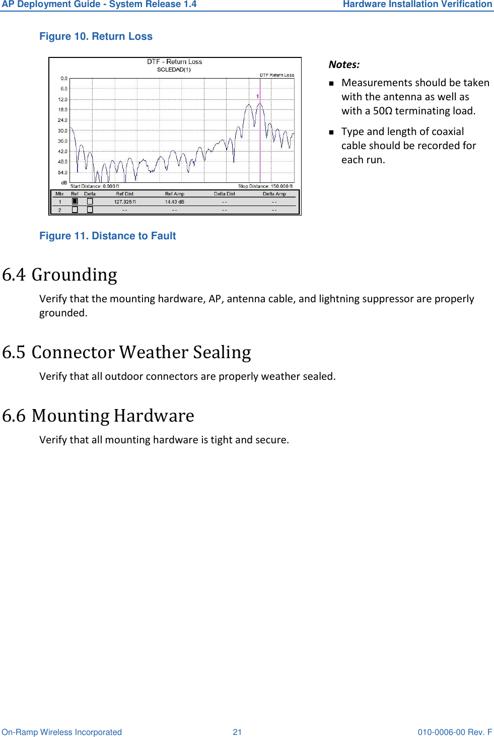
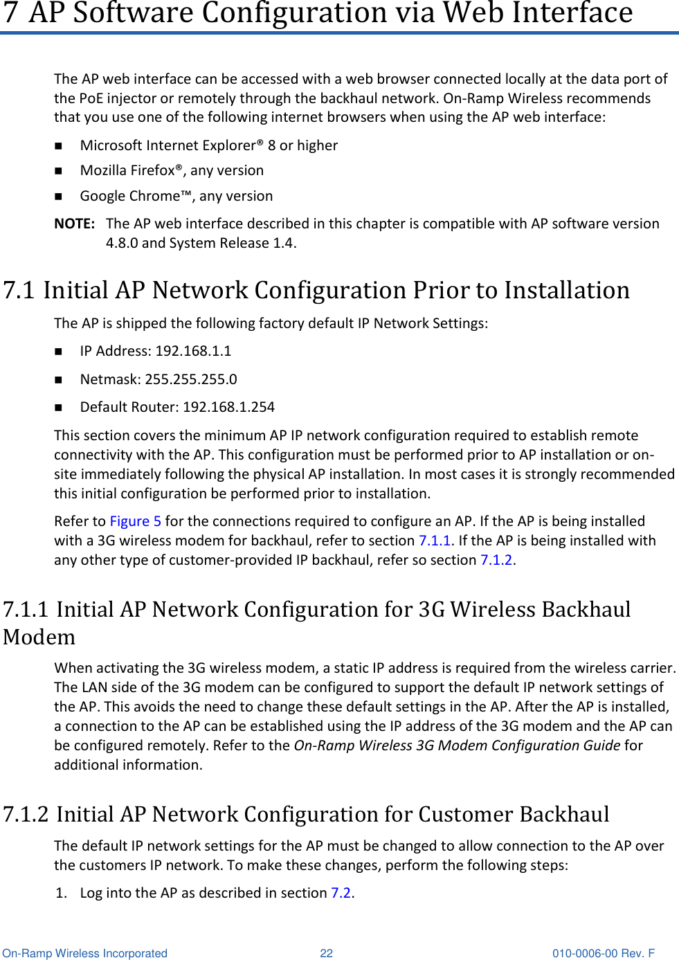
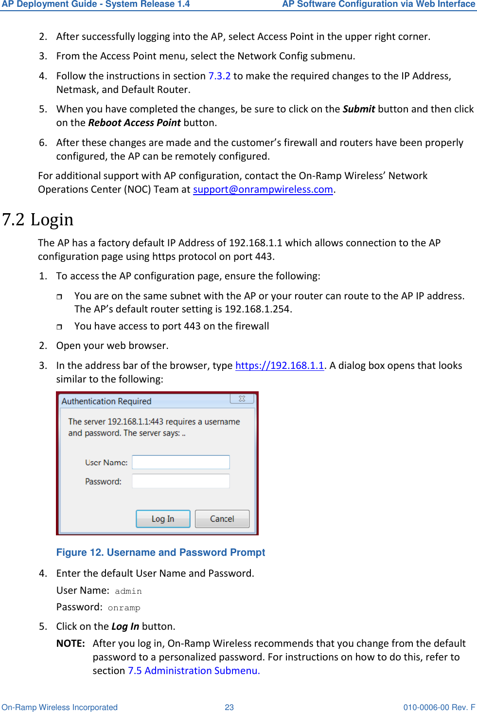
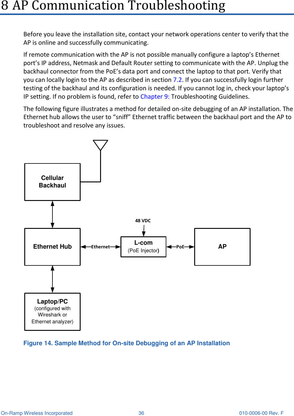
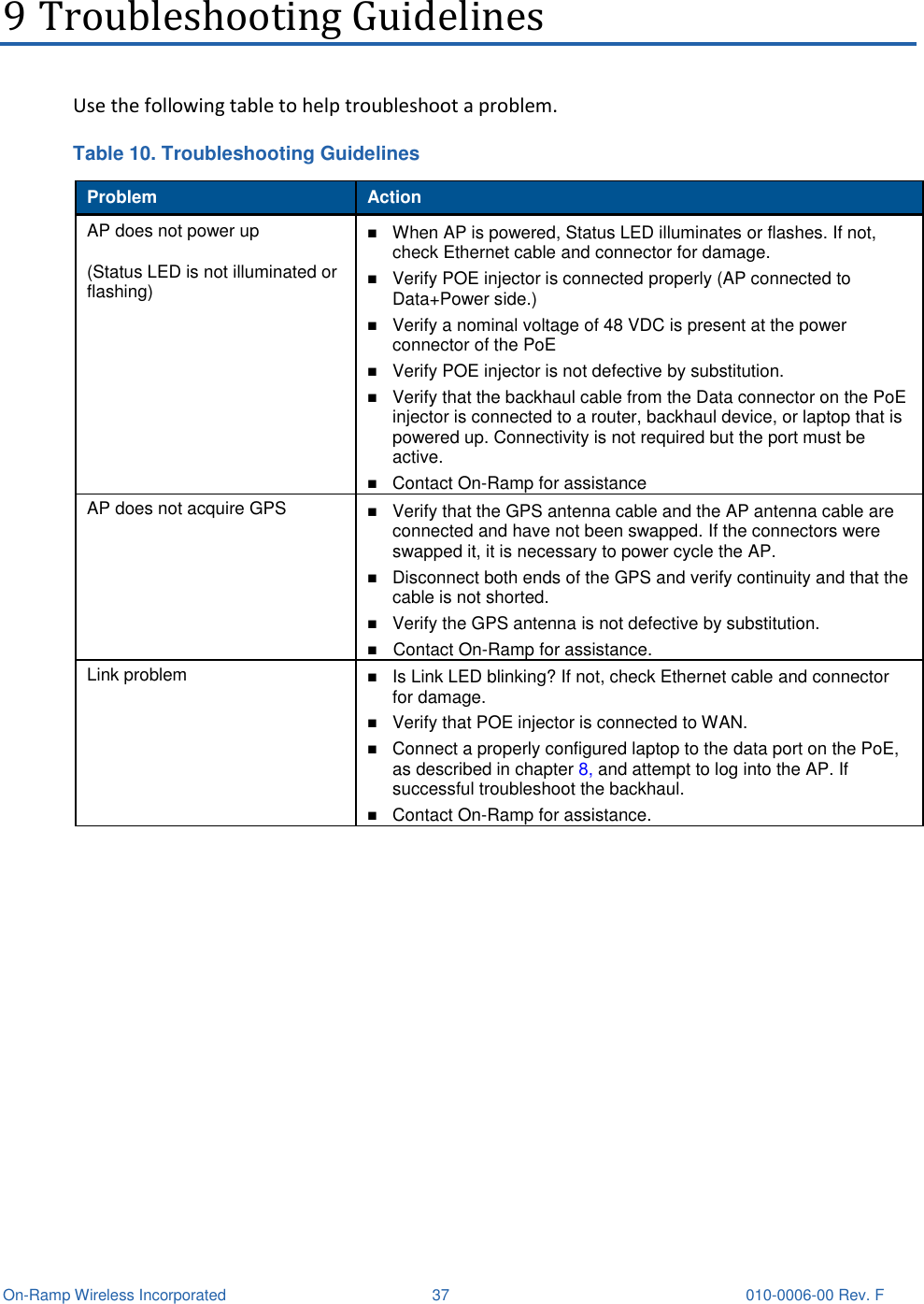
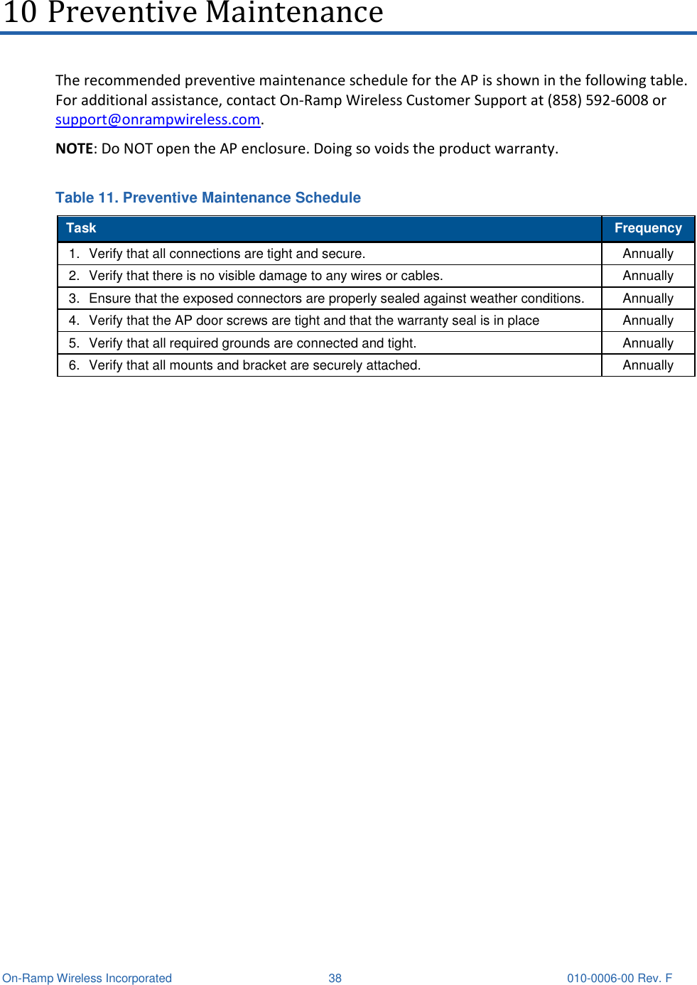
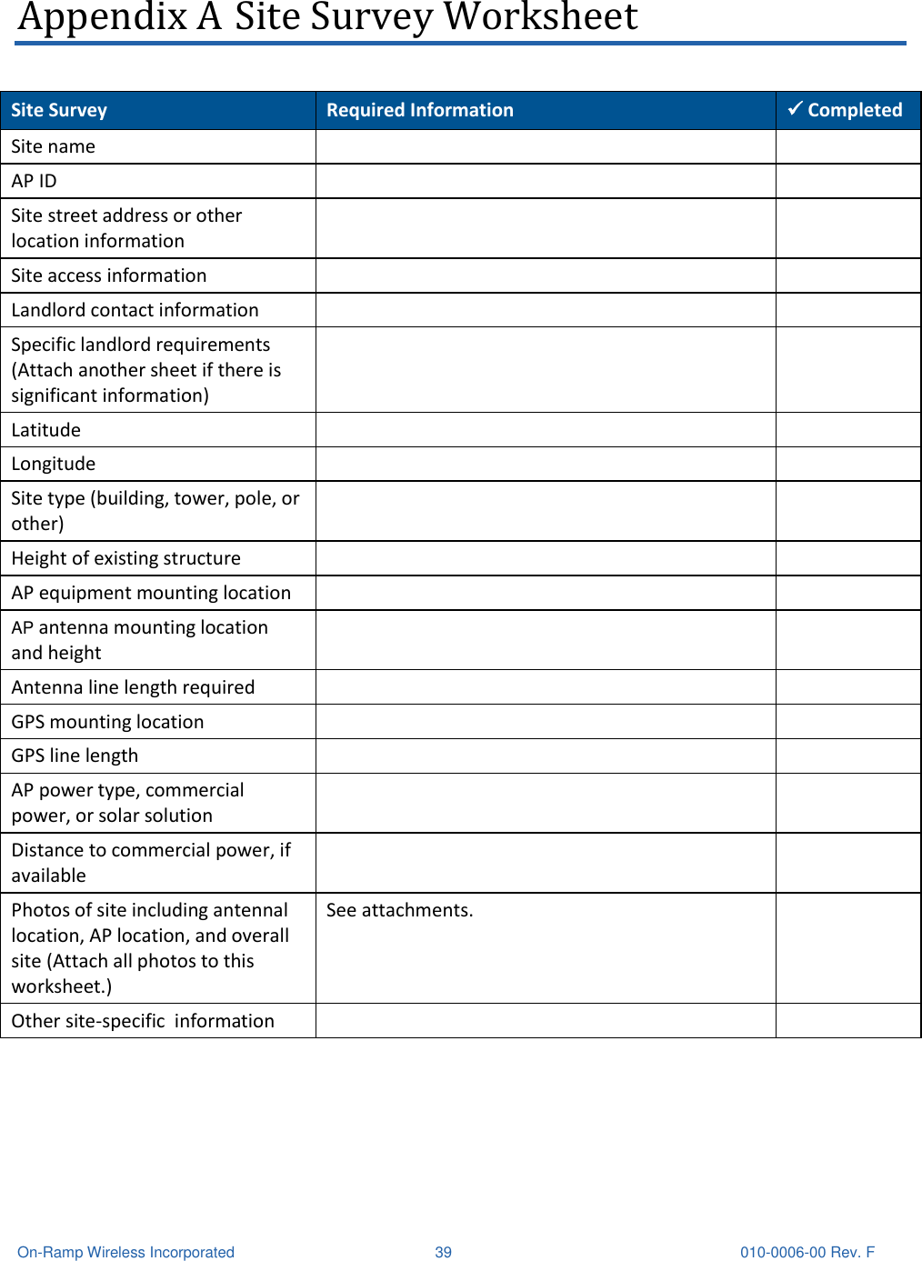
Ingenu ULPAP210 Sectorized RPMA Access Point User Manual AP Deployment Guide System Release 1 4

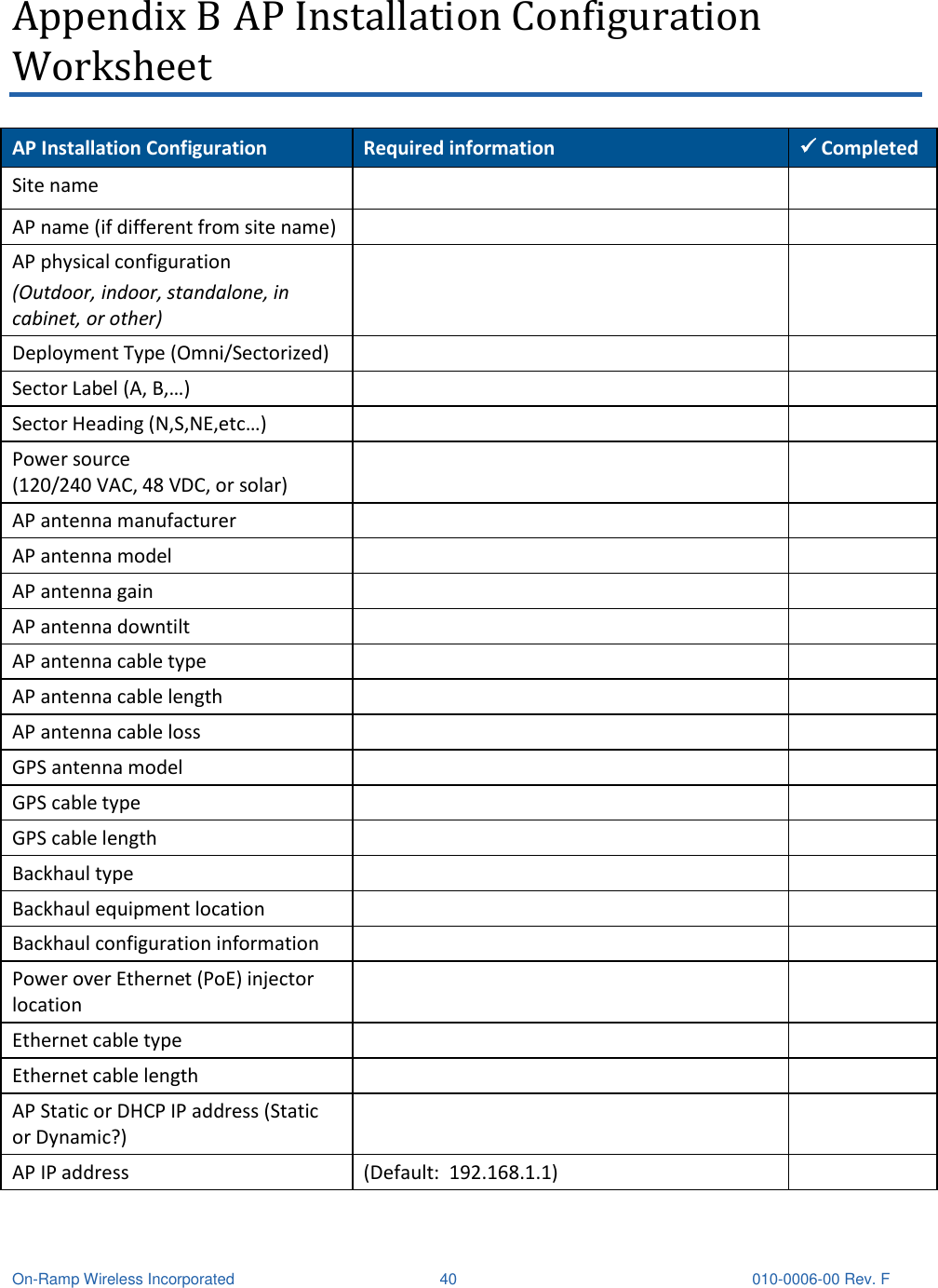
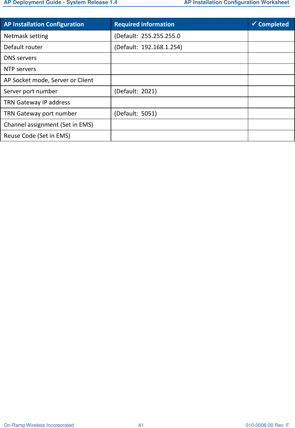
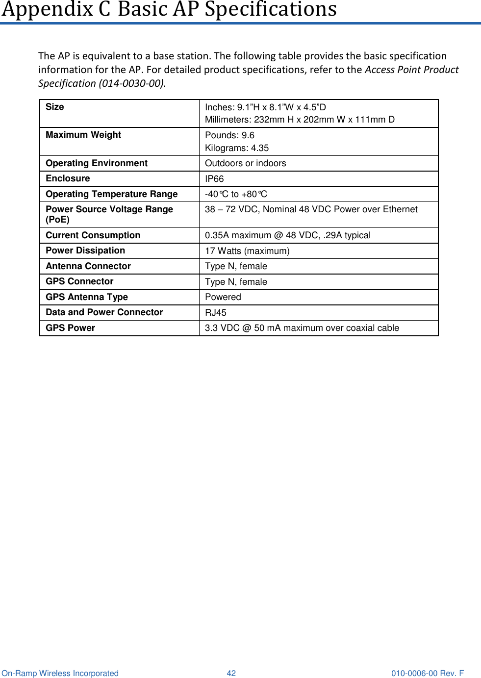
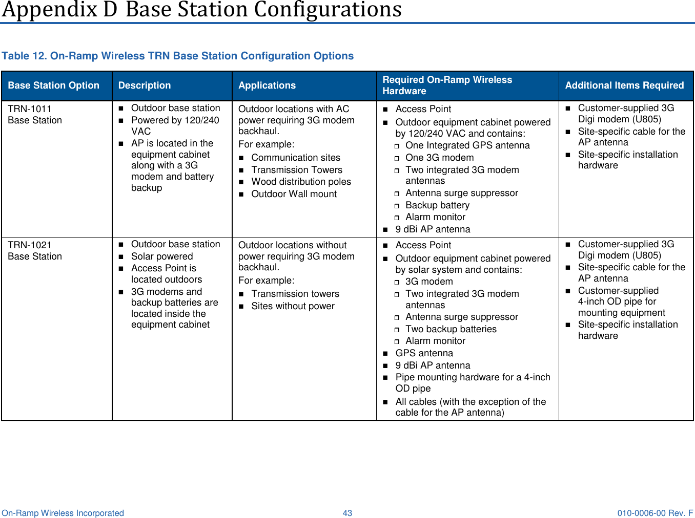
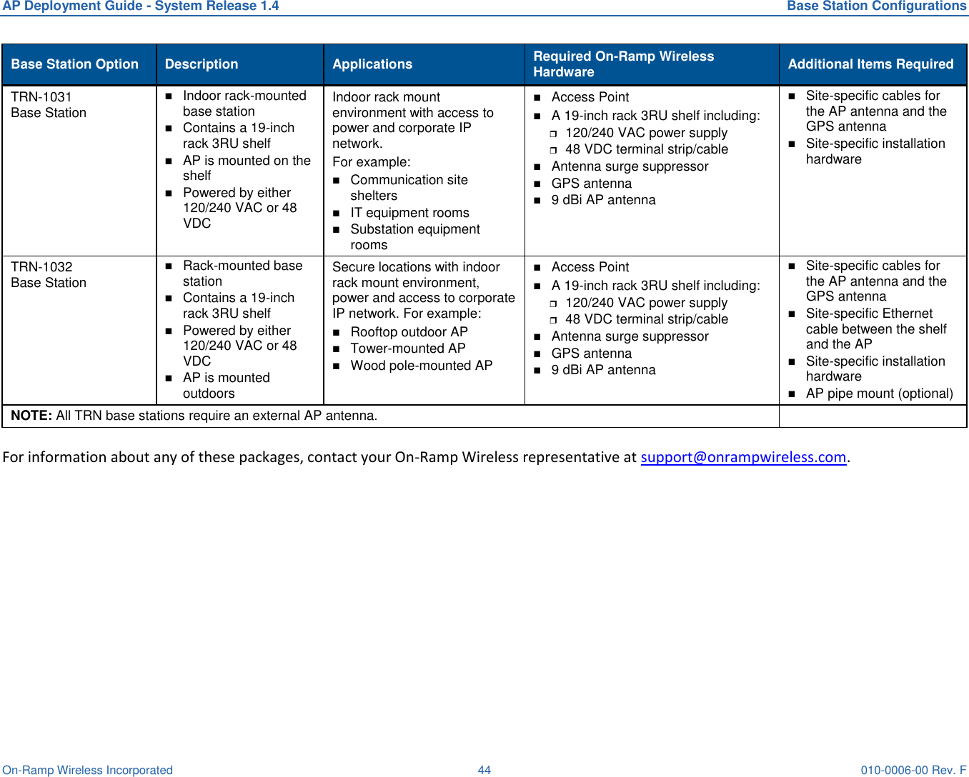
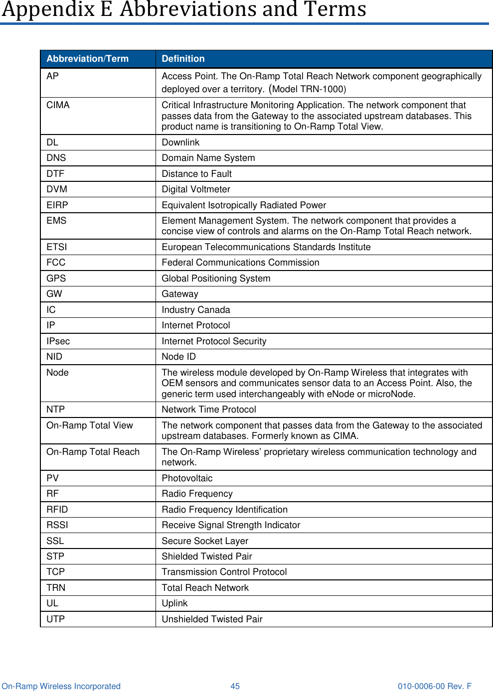
On-Ramp Wireless Sectorized RPMA Access Point AP Deployment Guide System Release 1 4

User Manual

           TOTAL REACH NETWORK On-Ramp  Wireless  Confidential and Proprietary.  This  document is not  to  be used, disclosed,  or  distributed  to anyone without express written consent from On-Ramp Wireless. The recipient of this document shall  respect the security  of  this  document  and  maintain  the  confidentiality  of  the  information  it  contains.  The  master  copy  of  this document  is  stored  in  electronic  format,  therefore  any  hard  or  soft  copy  used  for  distribution  purposes  must  be considered as uncontrolled. Reference should be made to On-Ramp Wireless to obtain the latest revision. Access Point Deployment Guide Model TRN-1000 System Release 1.4
  On-Ramp Wireless Incorporated 10920 Via Frontera, Suite 200 San Diego, CA 92127 U.S.A.  Copyright © 2015 On-Ramp Wireless Incorporated. All Rights Reserved.  The information disclosed in this document is proprietary to On-Ramp Wireless Inc., and is not to be used or disclosed to unauthorized persons without the written consent of On-Ramp Wireless. The recipient of this  document  shall  respect  the  security  of  this  document  and  maintain  the  confidentiality  of  the information it  contains.  The master  copy of  this  document  is  stored  in electronic  format,  therefore  any hard or soft copy used for distribution purposes must be considered as uncontrolled.  Reference should be made to On-Ramp Wireless to obtain the latest version. By accepting this material the recipient agrees that this material and the information contained therein is to be held in confidence and in trust and will not be used, copied, reproduced in whole or in part, nor its contents revealed in any manner to others without the express written permission of On-Ramp Wireless Incorporated. On-Ramp  Wireless  Incorporated  reserves  the  right  to  make  changes  to  the  product(s)  or  information contained herein without notice. No liability is assumed for any damages arising directly or indirectly by their use or application. The information provided in this document is provided on an “as is” basis.  This  document  contains  On-Ramp  Wireless  proprietary  information  and  must  be  shredded  when discarded. This  documentation  and  the  software  described  in  it  are  copyrighted  with  all  rights  reserved.  This documentation  and  the  software  may  not  be  copied,  except  as  otherwise  provided  in  your  software license or as expressly permitted in writing by On-Ramp Wireless, Incorporated. Any sample code herein is provided for your convenience and has not been tested or designed to work on any particular system configuration. It is provided “AS IS” and your use of this sample code, whether as provided  or  with any modification,  is at  your  own risk.  On-Ramp Wireless undertakes no liability or responsibility  with  respect  to  the  sample  code,  and  disclaims  all  warranties,  express  and  implied, including  without  limitation  warranties  on  merchantability,  fitness  for  a  specified  purpose,  and infringement. On-Ramp Wireless reserves all rights in the sample code, and permits use of this sample code only for educational and reference purposes. This technology and technical data may be subject to U.S. and international export, re-export or transfer (“export”) laws. Diversion contrary to U.S. and international law is strictly prohibited. Random Phase Multiple Access™ is a trademark of On-Ramp Wireless Incorporated. Other product and brand names may be trademarks or registered trademarks of their respective owners.  AP Deployment Guide - System Release 1.4 010-0006-00 Rev. F February 3, 2015
 On-Ramp Wireless Incorporated  iii 010-0006-00 Rev. F Contents 1 Introduction ........................................................................................................... 1 1.1 Overview .................................................................................................................................... 1 1.2 Referenced Documents ............................................................................................................. 3 2 Network Planning and Configuration Considerations ....................................... 4 2.1 Network Planning ....................................................................................................................... 4 2.2 Network Configuration ............................................................................................................... 4 2.3 Backhaul .................................................................................................................................... 5 3 Installation Prerequisites and Considerations ................................................... 6 3.1 Installation Prerequisites ............................................................................................................ 6 3.1.1 Site Survey ....................................................................................................................... 6 3.1.2 AP Installation Configuration ............................................................................................ 6 3.2 Installation Considerations ......................................................................................................... 7 3.2.1 AP Antenna ...................................................................................................................... 7 3.2.2 AP Antenna Cable ............................................................................................................ 7 3.2.3 GPS Antenna .................................................................................................................... 8 3.2.4 Antenna Cable Lightning Suppression and Grounding .................................................... 9 3.2.5 AP DC Power Requirement .............................................................................................. 9 3.2.6 PoE Injector .................................................................................................................... 10 3.2.7 Ethernet Cable ................................................................................................................ 10 3.2.8 Solar Power .................................................................................................................... 11 3.2.9 Outdoor Installation Hardware ........................................................................................ 11 4 Regulatory Warnings .......................................................................................... 12 4.1 Certifications ............................................................................................................................ 12 4.2 Transmit Power Restrictions .................................................................................................... 12 4.3 FCC Warnings – United States ................................................................................................ 12 4.4 IC Warnings - Canada.............................................................................................................. 13 4.5 RF Exposure Statement ........................................................................................................... 13 5 AP Installation ..................................................................................................... 15 5.1 AP and Ancillary Equipment .................................................................................................... 15 5.2 AP Installation Configurations .................................................................................................. 15 5.3 Base Station Configurations .................................................................................................... 16 5.4 General Grounding Guidelines ................................................................................................ 16 5.4.1 Grounding the AP and Antenna Cable Surge Suppressor ............................................. 16 5.4.2 Grounding the AP and GPS Antennas ........................................................................... 18
AP Deployment Guide - System Release 1.4  Contents On-Ramp Wireless Incorporated  iv 010-0006-00 Rev. F 5.5 AP Mounting Details................................................................................................................. 19 5.6 AP Pipe Mount Option ............................................................................................................. 19 6 Hardware Installation Verification ..................................................................... 20 6.1 Power Verification .................................................................................................................... 20 6.2 AP Antenna and GPS Cable DVM Test ................................................................................... 20 6.3 Antenna System Sweep Testing .............................................................................................. 20 6.4 Grounding ................................................................................................................................ 21 6.5 Connector Weather Sealing ..................................................................................................... 21 6.6 Mounting Hardware .................................................................................................................. 21 7 AP Software Configuration via Web Interface .................................................. 22 7.1 Initial AP Network Configuration Prior to Installation ............................................................... 22 7.1.1 Initial AP Network Configuration for 3G Wireless Backhaul Modem .............................. 22 7.1.2 Initial AP Network Configuration for Customer Backhaul ............................................... 22 7.2 Login ........................................................................................................................................ 23 7.3 Access Point Menu .................................................................................................................. 24 7.3.1 Startup Config Submenu ................................................................................................ 26 7.3.2 Network Config Submenu............................................................................................... 27 7.3.3 Procedure for Changing IP Address Settings ................................................................ 28 7.3.4 Ctrl Interface ................................................................................................................... 29 7.3.5 Specifications Submenu ................................................................................................. 30 7.3.6 FW Upgrade Submenu ................................................................................................... 30 7.3.7 Save Logs Submenu ...................................................................................................... 31 7.3.8 Site Survey Submenu ..................................................................................................... 32 7.4 Statistics Menu ......................................................................................................................... 33 7.4.1 ULP Stats ....................................................................................................................... 33 7.4.2 AP Stats Submenu ......................................................................................................... 34 7.5 Administration Submenu .......................................................................................................... 34 7.6 Home Menu .............................................................................................................................. 35 7.7 Regulatory Domain Setup ........................................................................................................ 35 8 AP Communication Troubleshooting ................................................................ 36 9 Troubleshooting Guidelines .............................................................................. 37 10 Preventive Maintenance ................................................................................... 38 Appendix A Site Survey Worksheet ..................................................................... 39 Appendix B AP Installation Configuration Worksheet ....................................... 40 Appendix C Basic AP Specifications ................................................................... 42
AP Deployment Guide - System Release 1.4  Contents On-Ramp Wireless Incorporated  v  010-0006-00 Rev. F Appendix D Base Station Configurations ............................................................ 43 Appendix E Abbreviations and Terms ................................................................. 45  Figures Figure 1. On-Ramp Wireless Access Point (TRN-1000) ................................................................. 1 Figure 2. High Level Diagram for Indoor Site Installation of AP and Equipment ............................. 2 Figure 3. High Level Diagram for Outdoor Site Installation of AP and Equipment .......................... 3 Figure 4. PCTEL GPS Model GPSL1-TMG-SPI-40NCB ................................................................. 9 Figure 5. Block Diagram Showing PoE Injector Connections ........................................................ 10 Figure 6. High Level Grounding Diagram ...................................................................................... 16 Figure 7. Grounding the AP ........................................................................................................... 17 Figure 8. Grounding the GPS and AP Antennas ........................................................................... 18 Figure 9. AP with Mounting Tabs Installed .................................................................................... 19 Figure 10. Return Loss................................................................................................................... 21 Figure 11. Distance to Fault ........................................................................................................... 21 Figure 12. Username and Password Prompt ................................................................................. 23 Figure 13. Sample Access Point Screen (with GPS Information) .................................................. 25 Figure 14. Sample Method for On-site Debugging of an AP Installation ....................................... 36  Tables Table 1. Software Versions .............................................................................................................. 1 Table 2. Attenuation at 2.4 GHz for Common Types of Antenna Cables ........................................ 8 Table 3. Surge Protector Mount Locations ...................................................................................... 9 Table 4. Tested Ethernet Cable and Connector Combinations ..................................................... 10 Table 5. GPS Fields on the Access Point Screen ......................................................................... 25 Table 6. Fields on the Startup Config Screen ................................................................................ 26 Table 7. Fields on the Network Config Screen .............................................................................. 27 Table 8. Fields on the Ctrl Interface Submenu Screen .................................................................. 29 Table 9. Troubleshooting Guidelines ............................................................................................. 37 Table 10. Preventive Maintenance Schedule ................................................................................ 38 Table 11. On-Ramp Wireless TRN Base Station Configuration Options ....................................... 43
 On-Ramp Wireless Incorporated  vi 010-0006-00 Rev. F Revision History Revision Release Date Change Description A April 9, 2012 Initial release. B September 14, 2012 Added block diagrams for PoE injector connections and AP communication troubleshooting. C September 26, 2012 Updated information clarifying the following:  RF cable loss measurement for AP configuration  Transmit power regulations  Antenna system sweep testing  Regulatory domain setup D November 30, 2012 Added Troubleshooting and Maintenance sections E April 25, 2013 Updated:  Product names where appropriate  Screen captures  Software configuration procedure F August 2, 2013 Added appendix for base station options and updated AP software configuration screens.
 On-Ramp Wireless Incorporated  1  010-0006-00 Rev. F 1 Introduction This document provides network planning, installation, configuration and preventive maintenance information for the Access Point model TRN-1000 as a part of the On-Ramp Wireless Total Reach Network (TRN). There are multiple configurations for the Access Point (AP) depending upon the country in which it will be used. For details, refer to the Access Point Product Specification (014-0030-00).  Figure 1. On-Ramp Wireless Access Point (TRN-1000)  This document is compatible with the software versions shown in the following table. Table 1. Software Versions Software Version System Release 1.4 AP 4.8.0   1.1 Overview The AP is the core component of the On-Ramp Wireless Total Reach Network (TRN) and TRN base station solutions. It provides the functionality of an RF transceiver, a data processor, and a data router. The RF transceiver operates in the unlicensed 2.4 GHz ISM band on one of thirty eight 1 MHz channels. The AP utilizes Time Division Duplexing and Direct Sequence Spread Spectrum with On-Ramp Wireless’ proprietary Random Phase Multiple Access (RPMA) modulation technique. The maximum transmit power of the AP’s transceiver (at the antenna connector) is +30 dBm (1 Watt). GPS is used for timing and synchronization. All endpoint devices designed with On-Ramp Total Reach Network technology communicate directly with TRN base stations installed on existing communication towers, rooftops, streetlights, substations, and other elevated sites to collect data or control the endpoint devices.  Base station networks are designed and deployed to meet coverage, capacity, and redundancy objectives.
AP Deployment Guide - System Release 1.4  Introduction On-Ramp Wireless Incorporated  2  010-0006-00 Rev. F On-Ramp Wireless APs are weatherproof with an IP 66 rating and can be installed indoors or outdoors. On-Ramp Wireless offers various base station configurations to support a wide variety of installations. Section 5.3 defines these pre-configured base station packages. This document focuses on the installation, configuration, and maintenance of the Access Point. For base station-specific information, see the installation manuals for each of the base stations. An AP installation requires:  A 10/100 IP-over-Ethernet connection with 128 Kbps minimum throughput for backhaul to the On-Ramp Wireless gateway  A Power-over-Ethernet (PoE) injector that combines power and data over the same Ethernet cable. The AP requires a passive PoE injector and cannot be powered directly from most switches NOTE:  The AP is not 802.3AF or 802.3AT compliant.   An AC or DC power source capable of supplying 48 VDC at a minimum of 25 Watts to the PoE injector.  For very long PoE cables, a 56 VDC power supply is recommended.   A  GPS antenna and cable  An AP antenna and cable  Coaxial Surge Protection (CSP) mounted at entrance into buildingExterior WallMinimal loss coaxial cable to maximize EIRPPoE InjectorBackhaul(10 Mb full duplex)Data/PoE, CAT5e (< 100 m)Mounting heightper network plan AC or DC sourceLMR-400Grounding kit(s) as per manufacturer recommendationsData/CAT5eClear view of skyGPS AntennaAP AntennaAccess Point(AP)INDOOR EQUIPMENT(within a building)OUTDOOR EQUIPMENTCSP Figure 2. High Level Diagram for Indoor Site Installation of AP and Equipment
AP Deployment Guide - System Release 1.4  Introduction On-Ramp Wireless Incorporated  3  010-0006-00 Rev. F Coaxial Surge Protection (CSP)Exterior WallMinimal loss coaxial cable to maximize EIRPPoE InjectorBackhaul(10 Mb full duplex)Data/PoE, CAT5e (< 100 m)Mounting height per network plan LMR-400Grounding kit(s) as per manufacturer recommendationsData/CAT5eCSPClear view of sky GPS AntennaAP AntennaAC or DC sourceAccess Point(AP)INDOOR EQUIPMENT (within a Building or Cabinet)OUTDOOR EQUIPMENT Figure 3. High Level Diagram for Outdoor Site Installation of AP and Equipment  NOTE:  The AP does not contain any user-serviceable components. Opening the AP voids the product warranty.   For questions or technical assistance, contact On-Ramp Wireless at support@onrampwireless.com.  1.2 Referenced Documents The following document provides additional details about the AP.  Access Point Product Specification (014-0030-00)  Provides detail about product specifications, characteristics, and requirements for the AP.  EMS Operator Guide (010-0045-00) Provides instruction on using On-Ramp Wireless Element Management System (EMS)  to manage and monitor the Access Point.  This document should be used for Access Point day-to-day operations and monitoring.
 On-Ramp Wireless Incorporated  4  010-0006-00 Rev. F 2 Network Planning and Configuration Considerations Prior to the installation of an AP at a new location, a number of network design and configuration decisions must be addressed. This chapter provides an overview of these decisions which should be reflected in the AP Installation Configuration Worksheet provided in Appendix B. Detailed network planning and configuration is outside the scope of this document. 2.1 Network Planning Network planning is critical to a successful AP installation and the reliable operation of an On-Ramp Total Reach Network. The following issues must be addressed in the network planning and design process.  Determine network coverage requirements  Establish network reliability requirements  Select and approve site and antenna locations  Predict TRN coverage with a propagation model  Select the appropriate AP antennas  Select the AP antenna cable type, determined by cable length, to minimize loss  Assign AP channel (frequency) and Reuse Code  Determine antenna cable attenuation  Determine AP transmit power setting  The maximum permissible Effective Radiated Power, ERP, is determined by the regulations for the country where the AP will be installed (e.g., ETSI, FCC). The actual ERP is determined by the AP’s transmit power output, antenna gain and antenna cable loss. NOTE:  The maximum ERP authorized by the FCC in the United States with an omni-directional antenna is +36 dBi. 2.2 Network Configuration The following AP network configuration settings must be determined by your network planning and configuration team and provided for AP configuration:  AP Name (Set in EMS)  System ID (Set in EMS)  Client or Server Mode operation  Static or DHCP IP address assignment
AP Deployment Guide - System Release 1.4  Network Planning and Configuration Considerations On-Ramp Wireless Incorporated  5  010-0006-00 Rev. F  AP IP address, if static  Netmask setting  Default router  DNS servers  NTP servers  Server port number  Gateway Hostname or IP Address  Gateway port number  Channel assignment (Set in EMS)  Reuse Code (Set in EMS, allows AP coexistence on the same channel)  AP antenna cable attenuation in dB (Set in EMS)  Transmit output power setting, most frequently automatically set by inserting antenna cable loss in dB when using the standard antenna for the country of operation. In the United States the standard antenna’s gain is 9 dBi for Omni deployment and 17dBi for Sectorized deployment. 2.3 Backhaul Backhaul is the interconnection of the APs in a network to the back office systems including the On-Ramp gateway and the element management system. The backhaul method to be used must be determined for each AP prior to installation. Common backhaul methods include the following:  Cellular/PCS 3G data modems  Existing Ethernet infrastructure  DSL links  Point-to-Point radio links  Microwave links NOTE:  A 10/100 Mb IP-over-Ethernet connection with 128 Kbps minimum throughput is required.
 On-Ramp Wireless Incorporated  6  010-0006-00 Rev. F 3 Installation Prerequisites and Considerations Before starting the actual physical installation of an AP, it is very important to complete the prerequisite tasks outlined in this chapter as well as take into account the installation considerations indicated. Information gathering templates are provided in the appendices of this document. 3.1 Installation Prerequisites 3.1.1 Site Survey A site survey should be conducted prior to installation for all AP sites. The site survey provides detailed, site-specific, information required to plan an AP installation and should be documented. See Appendix A for a Site Survey Worksheet template. A copy of this worksheet should be provided to the installer.  A site survey provides:  Site name  AP antenna mounting location and height  AP name (if different from site name)  Antenna line length required  Site street address or other location  GPS antenna mounting location  Site access information  GPS antenna cable length  Landlord contact information  Specific landlord requirements   AP power type, commercial power, solar solution or other  Latitude  Distance to available power  Longitude  Site type (building, tower, pole, or other)  Photos of site including antennal location, AP location, and the overall site  Height of existing structure  Other site-specific  information  AP and equipment mounting locations  3.1.2 AP Installation Configuration The AP installation configuration should be documented and provided to the installer prior to the start of the installation. See Appendix B for an AP Installation Configuration Worksheet template. This worksheet provides the following site-specific equipment details and AP configuration information:  Site name  AP antenna gain   AP name (if different from site name)  AP antenna downtilt, if required  Deployment Type  (Omni /Sectorized)  AP physical configuration (outdoor, indoor, and base station type)  Sector Label (A,B,…)  Sector Heading (N,S,NE,etc…)  AP antenna cable type  AP antenna cable length
AP Deployment Guide - System Release 1.4  Installation Prerequisites and Considerations On-Ramp Wireless Incorporated  7  010-0006-00 Rev. F  Power source  (120/240 VAC, 48 VDC, or Solar)  AP antenna cable loss  GPS antenna model  AP antenna manufacturer  GPS cable type  AP antenna model  GPS cable length  Backhaul type  Default router  Backhaul equipment location  DNS servers  Backhaul configuration information  NTP servers  AP and other equipment installation location  Client or server mode of operation  Gateway hostname or IP address  Ethernet cable type and length, if required  Gateway port number  AP IP Address type, Static or Dynamic  Server port  AP IP Address assignment, if static  Channel assignment  Netmask setting  Reuse code 3.2 Installation Considerations When planning a new AP installation, the following items must be considered. 3.2.1 AP Antenna The AP antenna should be mounted at a location that minimizes physical obstructions between the antenna and the endpoints with which it will be communicating. Rooftop installations create the largest concern in this area. Antenna placement and height are very important to maximize network performance. The AP antenna should be securely mounted in a vertical position. The AP antenna cable is connected to a type-N female connector on the AP.    There are a variety of antenna options available to address the regulatory requirements of different countries. See the Access Point Product Specification (014-0030-00) for additional details. 3.2.2 AP Antenna Cable A 50 ohm low loss coaxial cable is used to connect the antenna to the AP. The type of cable is selected based on the length of the cable run and network design requirements. For short runs, a ½ inch cable such as Andrew LDF4-50A is recommended. For longer runs, a  inch cable or 1⅝ inch cable may be used to reduce the cable attenuation. The antenna cable should always be attached to the tower or other structure with clamps at the spacing recommended by the manufacturer. It is also very important to maintain the minimum bending radius recommended by the manufacturer to avoid kinking the cable during installation. When using an antenna cable larger than ½ inch, ½ inch LDF4-50A jumpers with type-N male connectors, typically 3 feet to 6 feet long, should be installed between the antenna cable and both the antenna and the AP to minimize the chance of damage to their connectors. The AP and the AP antenna use type “N” female connectors. NOTE 1:  The total RF cable loss from AP Antenna connector to the antenna must be calculated or measured with antenna system test equipment during installation as detailed in section
AP Deployment Guide - System Release 1.4  Installation Prerequisites and Considerations On-Ramp Wireless Incorporated  8  010-0006-00 Rev. F 6.3 Antenna System Sweep Testing. This value in dB is used when configuring the AP in the EMS. NOTE 2:   All outdoor antenna cable connections must be weather sealed in an appropriate manner. The table below shows the attenuation for common types of antenna lines. Table 2. Attenuation at 2.4 GHz for Common Types of Antenna Cables Model Size dB/25 ft dB/50 ft dB/100 ft dB/150 ft dB/200 ft LMR-400 .40 inch 1.7 3.4 6.8 10.2 13.6 FSJ4-50B ½ inch  1.5 3.1 6.1 9.2 12.2 LDF4-50A ½ inch .9 1.9 3.7 5.6 7.4 AVA5-50 ⅞ inch .5 1.0 1.9 2.9 3.8 3.2.3 GPS Antenna The GPS antenna provides timing signals to the AP. It should be mounted so that it has a clear view of the sky. A mounting location should be chosen that minimizes shadowing from trees or structures. NOTE:  The GPS antenna should be mounted at least one meter away from the AP antenna to minimize the chance of interference. In normal operation, the AP requires GPS synchronization for precision timing of all nodes on the network. To provide a reliable GPS signal, the AP has a built-in GPS receiver which requires an externally connected GPS antenna. The GPS antenna cable is connected to a type-N female connector on the AP.  Many different GPS antennas are available but On-Ramp Wireless recommends using the PCTEL GPS antenna model GPSL1-TMG-SPI-40NCB for the following reasons: 1. The PCTEL GPS antenna has a low noise, high gain amplifier which is well-suited to address cable attenuation when the GPS antenna mounting location requires a long length of cable. Up to a 20 dB cable loss is acceptable when using this high gain antenna.  2. The PCTEL GPS antenna provides integrated, onboard, lightning protection that minimizes the need for a downstream, inline surge suppressor. The GPS antenna must be properly grounded. See figure 4. If using an external surge suppressor, it must be a “DC pass-through” type.
AP Deployment Guide - System Release 1.4  Installation Prerequisites and Considerations On-Ramp Wireless Incorporated  9  010-0006-00 Rev. F  Figure 4. PCTEL GPS Model GPSL1-TMG-SPI-40NCB  The PCTEL GPSL1-TMG-SPI-40NCB GPS antenna has a type-N female connector.  NOTE:  Most GPS antennas have an Low Noise Amplifier (LNA) that requires power from the AP. The AP supplies 3.3 V at up to 50 ma. If this current is exceeded, the AP detects the excess current and shuts down its GPS power supply. When this occurs, the AP sends a GPS antenna fault message back to the EMS. The AP must be power cycled to restore power to the GPS antenna. 3.2.4 Antenna Cable Lightning Suppression and Grounding A coaxial surge suppressor must be installed at the location shown in the table below and must be connected with a #10 gauge or larger stranded wire to an appropriate ground for lightning protection. In most tower installations the outer shield of the AP antenna cable must be grounded with one or more grounding kits provided by the antenna cable manufacturer. The grounding kits must be connected to appropriate building or tower grounds using a #2 gauge wire. The mounting pipe for the antenna should be grounded to the same point if it is not attached to a grounded structure. Table 3. Surge Protector Mount Locations Coaxial System Mount Location Mount Location of Surge Protector Indoors Entrance to the first external wall Outdoors Antenna connector of the Access Point Outdoor Enclosure Entrance to the enclosure 3.2.5 AP DC Power Requirement The AP is powered over the Ethernet port using a PoE injector. The acceptable power source voltage range is 38 – 72 VDC.  At the nominal input voltage of 48 VDC the typical input current is 0.3 Amps. The maximum input power dissipation is 17 Watts. When connecting to a 48 VDC power system’s distribution panel it should be fused with a minimum of a ½ Amp slow-blow fuse. The maximum fuse or circuit breaker size should be 2 Amps.
AP Deployment Guide - System Release 1.4  Installation Prerequisites and Considerations On-Ramp Wireless Incorporated  10 010-0006-00 Rev. F 3.2.6 PoE Injector A standard PoE (Power over Ethernet) injector is used to apply power to the AP. An example of an approved device is the L-com HyperLink BT-CAT5-P1 Single-Port CAT-5 Midspan/Injector (also known as PoE Passive Splitter). When connected to an outdoor AP the PoE injector must be properly grounded for lightning and surge protection. The following figure illustrates a typical setup utilizing the PoE injector. Laptop(configured to AP’s IP subnet)L-com(PoE Injector)APEthernet PoE48 VDCAP must be connected to the “Data + Power” side of the injector Figure 5. Block Diagram Showing PoE Injector Connections 3.2.7 Ethernet Cable The Ethernet cable connection to the AP provides both data and DC power. The maximum Ethernet cable length is 328 feet (100 meters). A quality Cat5e or Cat6 cable is required. For most applications, an Unshielded Twisted Pair (UTP) cable with solid conductors is recommended.   NOTE:  Shielded Ethernet cable is not recommended.  The following table provides a list of tested Ethernet cables and connector combinations. Table 4. Tested Ethernet Cable and Connector Combinations Cable Type Manufacturer Part Number RJ45 Connector Type Manufacturer Part Number CAT 5E, UTP Stranded, 24AWG Cable 10X6-021SH www.CableWholesale.com CAT 5E UTP RJ45 Connectors, for Stranded Cable SW-22342 http://sewelldirect.com CAT 5E UTP Solid, 24 AWG Cable DC-5E8-RD-1K-L Pan Pacific www.wallcoinc.com CAT 5E UTP RJ45 Connectors, for Solid Cable CN150-45-1 Mfg: Abergetty Supplied by: www.deepsurplus.com CAT 5E, STP Solid, 24AWG Cable 10X6-521TH www.CableWholesale.com CAT 5E STP RJ45 Connectors, for Solid Cable SW-22350 http://sewelldirect.com CAT 5E, STP Stranded, 24AWG Cable 10X6-521SH www.CableWholesale.com CAT 5E STP RJ45 Connectors, for Stranded CN150-45-11 Mfg: Abergetty Supplied by: www.deepsurplus.com CAT 6, UTP Stranded Cable 10X8-071SH www.CableWholesale.com CAT 6 UTP RJ45 Connectors, for Stranded Cable SW-22346 http://sewelldirect.com
AP Deployment Guide - System Release 1.4  Installation Prerequisites and Considerations On-Ramp Wireless Incorporated  11 010-0006-00 Rev. F Cable Type Manufacturer Part Number RJ45 Connector Type Manufacturer Part Number CAT 6, UTP Solid Cable 10X8-081TH www.CableWholesale.com CAT 6 UTP RJ45 Connectors, for Solid Cable CN150-45-4 Mfg: Abergetty Supplied by: www.deepsurplus.com CAT 6 STP Solid 10X8-591NH www.CableWholesale.com CAT 6 STP RJ45 Connectors, for Solid Cable CN150-45-10 Mfg: Abergetty Supplied by: www.deepsurplus.com  NOTE:  It is very important that connectors be specified for the cable being used. As an example, if using Cat5e solid conductor cable, the connectors should be specified for Cat5e solid conductor cable. Some connectors are specified for both solid and stranded conductors. Always use an RJ45 crimping tool that is specified for use with the connectors being used. During the installation of the Ethernet cable, a pulling force of 25 pounds should not be exceeded. The bending radius of the cable should never be less than four times its diameter. Ethernet cable should not be deformed by tightly cinched cable ties. Shielded Ethernet cable may be required in cases where the cable is installed in close proximity to equipment or conductors generating strong electromagnetic fields. In this case follow Shielded Twisted Pair (STP) installation guidelines. 3.2.8 Solar Power Solar Power is recommended for sites where commercial power is not available or is not cost effective to install. The required size for the solar panel and battery system is strongly influenced by the geographic area in which it will be used. On-Ramp Wireless offers a solar powered base station solution that may be appropriate for your application. Contact On-Ramp Wireless at support@onrampwireless.com for more information. 3.2.9 Outdoor Installation Hardware All outdoor installation hardware such as mounting brackets, pipe clamps, u-bolts, bolts, nuts and washers should either be galvanized or stainless steel. This reduces deterioration due to corrosion, oxidation, and rust.  NOTE:  All exposed antenna system connectors must be sealed against moisture using industry standard techniques.
 On-Ramp Wireless Incorporated  12 010-0006-00 Rev. F 4 Regulatory Warnings 4.1 Certifications The AP is designed to meet regulations for world-wide use.  For information on the most current certifications, refer to the Access Point Product Specification (014-0030-00). 4.2 Transmit Power Restrictions Transmit power restrictions vary by country/agency. For details about antenna and transmit power restrictions, refer to the Access Point Product Specification (014-0030-00). In the United States, the AP is certified under two FCC IDs corresponding to two types of deployment:  One, Omni, for use with an omni-directional antenna;  The other, Sectorized, for use with directional antennas.  A professional installation of the AP is required.  A professional installation installment of the AP must comply with the antenna configurations below, based on the deployment type.  FCC ID Deployment Type Max Antenna Gain Antenna Type XTE-ULPAP110 Omni 9 dBi Omni-directional XTE-ULPAP210 Sectorized 17 dBi Directional Table 5: United States acceptable FCC deployment scenarios 4.3 FCC Warnings – United States This device complies with part 15 of the Federal Communications Commission (FCC) Rules. Operation is subject to the following two conditions:  1. This device may not cause harmful interference. 2. This device must accept any interference received, including interference that may cause undesired operation. Changes or modifications not expressly approved by the manufacturer could void the user’s authority to operate the equipment. NOTE: This equipment has been tested and found to comply with the limits for a Class B digital device, pursuant to Part 15 of the FCC Rules. These limits are designed to provide reasonable protection against harmful interference in a residential installation.
AP Deployment Guide - System Release 1.4  Regulatory Warnings On-Ramp Wireless Incorporated  13 010-0006-00 Rev. F WARNING: This equipment generates, uses, and can radiate radio frequency energy. If not installed and used in accordance with the instructions, this equipment may cause harmful interference to radio communications. However, there is no guarantee that interference will not occur in a particular installation. If this equipment does cause harmful interference to radio or television reception, which can be determined by turning the equipment off and on, the user is encouraged to try to correct the interference by one or more of the following measures:  Re-orient or relocate the receiving antenna.  Increase the separation between the equipment and receiver.  Connect the equipment into an outlet on a circuit different from that to which the receiver is connected.  Consult the dealer or an experienced radio/TV technician for help. 4.4 IC Warnings - Canada The installer of this radio equipment must ensure that the antenna is located or pointed so that it does not emit RF field in excess of Health Canada limits for the general population. Consult Safety Code 6 which is obtainable from Health Canada’s website http://www.hc-sc.gc.ca/index-eng.php. Operation is subject to the following two conditions: 1. This device may not cause harmful interference. 2. This device must accept any interference received, including interference that may cause undesired operation. To reduce potential radio interference to other users, select the antenna type and its gain so that the equivalent isotropically radiated power (EIRP) is not more than that permitted for successful communication. Canadian Two Part Warning Statement:  This device complies with Industry Canada licence-exempt RSS standard(s). Operation is subject to the following two conditions: (1) this device may not cause interference, and (2) this device must accept any interference, including interference that may cause undesired operation of the device. Le présent appareil est conforme aux CNR d'Industrie Canada applicables aux appareils radio exempts de licence. L'exploitation est autorisée aux deux conditions suivantes : (1) l'appareil ne doit pas produire de brouillage, et (2) l'utilisateur de l'appareil doit accepter tout brouillage radioélectrique subi, même si le brouillage est susceptible d'en compromettre le fonctionnement.  4.5 RF Exposure Statement  FCC ID: XTE-ULPAP110. IC: 8655A-ULPAP110. This device is only authorized for use in fixed and mobile applications. To meet FCC and other national radio frequency (RF) exposure
AP Deployment Guide - System Release 1.4  Regulatory Warnings On-Ramp Wireless Incorporated  14 010-0006-00 Rev. F requirements, the antenna for this device must be installed to ensure a separation distance of at least 20cm (8 inches) from the antenna to a person.
 On-Ramp Wireless Incorporated  15 010-0006-00 Rev. F 5 AP Installation 5.1 AP and Ancillary Equipment The AP installation includes installing the AP itself and the ancillary equipment listed below:  Access Point (AP)  AP antenna  AP antenna cable (50 ohm coaxial cable)  AP antenna  cable lightning suppressor  GPS antenna   GPS antenna cable (50 ohm coaxial cable)  PoE injector, powered by 48 VDC  Site-specific power solution providing 48 VDC to the PoE, if not using the 120/240 VAC powered base station cabinet or the solar powered base station  Backhaul equipment  Site-specific mounting hardware  NOTE: On-Ramp Wireless recommends that a backup power solution be utilized to power the AP in the event of a power failure. The backup power solution should be designed to meet customer requirements for the number of hours of backup power. 5.2 AP Installation Configurations The AP’s small size (9.1”H x 8.1”W x 4.5”D) and light weight allows for many installation configurations. For basic AP specifications, refer to Appendix C. The AP is designed to be installed indoors or outdoors. It may be mounted in any position indoors but should be mounted with its connectors facing down when installed outdoors. The AP may be installed in an equipment cabinet with its ancillary equipment if desired.  Types of installation configurations include:  Outdoor non-penetrating  roof mounts on building   Indoor or outdoor wall attachment  Pipe mounting  Tower mounting  Utility pole mounting
AP Deployment Guide - System Release 1.4  AP Installation On-Ramp Wireless Incorporated  16 010-0006-00 Rev. F 5.3 Base Station Configurations On-Ramp Wireless offers pre-configured base station packages. For details, refer to Appendix D: Base Station Configurations. 5.4 General Grounding Guidelines The following grounding information is provided as a guideline when installing the AP in any configuration. AP Antenna CSP = Coaxial Surge ProtectorCSPAccess Point (AP)GPS Antenna Equipment CabinetAdditionalSector Figure 6. High Level Grounding Diagram 5.4.1 Grounding the AP and Antenna Cable Surge Suppressor A ground wire may be attached underneath one of the AP mounting bolts. A ground wire must be attached to the ground terminal on the inline coaxial surge protector which is inserted
AP Deployment Guide - System Release 1.4  AP Installation On-Ramp Wireless Incorporated  17 010-0006-00 Rev. F between the AP’s type N female antenna connector and the AP antenna cable. An example is shown in the following figure.   Figure 7. Grounding the AP
AP Deployment Guide - System Release 1.4  AP Installation On-Ramp Wireless Incorporated  18 010-0006-00 Rev. F 5.4.2 Grounding the AP and GPS Antennas If the AP and GPS antennas are not attached to grounded metal structures a ground wire should be attached to the base of both antennas. An example of grounding these two antennas is shown in the following figure.  Figure 8. Grounding the GPS and AP Antennas
AP Deployment Guide - System Release 1.4  AP Installation On-Ramp Wireless Incorporated  19 010-0006-00 Rev. F 5.5 AP Mounting Details The AP is supplied with four mounting tabs that facilitate attaching the AP to a wall, in a cabinet, or to a strut channel, if required. The mounting tabs are attached to the AP by the installer using four provided, 5/16 inch self-tapping, hex head bolts. See the mounting tabs shown in Error! Reference source not found.. Mounting Tabs Installed Figure 9. AP with Mounting Tabs Installed 5.6 AP Pipe Mount Option On-Ramp Wireless offers an optional pipe mount kit for the AP. This kit provided two 8-inch lengths of strut channel that have been drilled to allow attachment to the top and bottom holes on the back of the AP. The same self-tapping bolts provided with the AP are used to attach the strut channel in place of the mounting tabs. After attaching the strut channel to the AP, it can now be attached to any size of pipe using standard strut channel pipe clamps or conduit clamps.
 On-Ramp Wireless Incorporated  20 010-0006-00 Rev. F 6 Hardware Installation Verification 6.1 Power Verification Prior to applying power to the AP, confirm with a Digital Voltmeter (DVM) that the DC voltage is correct at the PoE injector. The DC voltage should be between 48 VDC and 54 VDC. NOTE:  The AP its self is not polarity sensitive, however, it is recommended that the barrel of the PoE power plug be at ground potential if the power system is grounded. 6.2 AP Antenna and GPS Cable DVM Test Prior to weather sealing the AP antenna and GPS antenna connectors, disconnect both cables at both ends and verify continuity between center pins and verify that neither cable is shorted.  6.3 Antenna System Sweep Testing  The combined TRN antenna system (including the antenna, cables, and lightning suppressor) should be “sweep tested” for Return Loss and Attenuation using an antenna analyzer such as an Anritsu Site Master™. The antenna system should be swept across the frequencies of interest, 2.400 GHz – 2.480 GHz. The Return Loss should be greater than 17 dB across the frequency range and the total attenuation should be as low as possible, generally less than 5 dB. The antenna system attenuation (loss) should be noted for use when configuring the AP within the EMS system. If the Return Loss is not acceptable, the antenna should be disconnected and the antenna line should be terminated with a 50 ohm load. The Return Loss test should be repeated. If the antenna line Return Loss is now greater than 20 dB and is flat across the frequency range, the antenna should be replaced. If the Return Loss is not acceptable, the antenna cable system should be tested using the Distance to Fault (DTF) capability in the antenna analyzer to locate the problem.   Notes:  Measurement is required to be > 20 dB for coaxial cable and connectors.   Overall return loss with antenna should be > 17 dB.
AP Deployment Guide - System Release 1.4  Hardware Installation Verification On-Ramp Wireless Incorporated  21 010-0006-00 Rev. F Figure 10. Return Loss   Notes:  Measurements should be taken with the antenna as well as with a 50Ω terminating load.   Type and length of coaxial cable should be recorded for each run. Figure 11. Distance to Fault 6.4 Grounding Verify that the mounting hardware, AP, antenna cable, and lightning suppressor are properly grounded. 6.5 Connector Weather Sealing Verify that all outdoor connectors are properly weather sealed. 6.6 Mounting Hardware Verify that all mounting hardware is tight and secure.
 On-Ramp Wireless Incorporated  22 010-0006-00 Rev. F 7 AP Software Configuration via Web Interface The AP web interface can be accessed with a web browser connected locally at the data port of the PoE injector or remotely through the backhaul network. On-Ramp Wireless recommends that you use one of the following internet browsers when using the AP web interface:  Microsoft Internet Explorer® 8 or higher  Mozilla Firefox®, any version  Google Chrome™, any version NOTE:  The AP web interface described in this chapter is compatible with AP software version 4.8.0 and System Release 1.4. 7.1 Initial AP Network Configuration Prior to Installation The AP is shipped the following factory default IP Network Settings:  IP Address: 192.168.1.1  Netmask: 255.255.255.0  Default Router: 192.168.1.254 This section covers the minimum AP IP network configuration required to establish remote connectivity with the AP. This configuration must be performed prior to AP installation or on-site immediately following the physical AP installation. In most cases it is strongly recommended this initial configuration be performed prior to installation.  Refer to Figure 5 for the connections required to configure an AP. If the AP is being installed with a 3G wireless modem for backhaul, refer to section 7.1.1. If the AP is being installed with any other type of customer-provided IP backhaul, refer so section 7.1.2. 7.1.1 Initial AP Network Configuration for 3G Wireless Backhaul Modem When activating the 3G wireless modem, a static IP address is required from the wireless carrier. The LAN side of the 3G modem can be configured to support the default IP network settings of the AP. This avoids the need to change these default settings in the AP. After the AP is installed, a connection to the AP can be established using the IP address of the 3G modem and the AP can be configured remotely. Refer to the On-Ramp Wireless 3G Modem Configuration Guide for additional information. 7.1.2 Initial AP Network Configuration for Customer Backhaul The default IP network settings for the AP must be changed to allow connection to the AP over the customers IP network. To make these changes, perform the following steps: 1. Log into the AP as described in section 7.2.
AP Deployment Guide - System Release 1.4  AP Software Configuration via Web Interface On-Ramp Wireless Incorporated  23 010-0006-00 Rev. F 2. After successfully logging into the AP, select Access Point in the upper right corner.  3. From the Access Point menu, select the Network Config submenu.  4. Follow the instructions in section 7.3.2 to make the required changes to the IP Address, Netmask, and Default Router. 5. When you have completed the changes, be sure to click on the Submit button and then click on the Reboot Access Point button. 6. After these changes are made and the customer’s firewall and routers have been properly configured, the AP can be remotely configured. For additional support with AP configuration, contact the On-Ramp Wireless’ Network Operations Center (NOC) Team at support@onrampwireless.com. 7.2 Login  The AP has a factory default IP Address of 192.168.1.1 which allows connection to the AP configuration page using https protocol on port 443.  1. To access the AP configuration page, ensure the following:  You are on the same subnet with the AP or your router can route to the AP IP address. The AP’s default router setting is 192.168.1.254.  You have access to port 443 on the firewall 2. Open your web browser. 3. In the address bar of the browser, type https://192.168.1.1. A dialog box opens that looks similar to the following:    Figure 12. Username and Password Prompt 4. Enter the default User Name and Password. User Name:  admin Password:  onramp 5. Click on the Log In button. NOTE:  After you log in, On-Ramp Wireless recommends that you change from the default password to a personalized password. For instructions on how to do this, refer to section 7.5 Administration Submenu.
AP Deployment Guide - System Release 1.4  AP Software Configuration via Web Interface On-Ramp Wireless Incorporated  24 010-0006-00 Rev. F 6. After logging in, the Access Point menu page displays as shown in the next section. 7.3 Access Point Menu   Block A shows the three menus (i.e., Home, Access Point, and Statistics) that can be used to navigate to different configuration pages.  Block B shows the seven submenus under the Access Point menu. These submenus are described in the following sections.  Startup Config – Displays RF parameter information  Network Config – Allows  configuration of the IP network connection  Ctrl Interface – Allows configuration of the Control Interface with the On-Ramp Wireless gateway.  Specifications – Displays AP-specific configuration information  FW Upgrade – In this software release performing a Firmware Upgrade is not supported through the web interface.  Save Logs – Allows AP logs to be saved to a file for diagnostic purposes  Site Survey – Provides an Offline utility to perform an AP Site Survey which evaluates the interference level on all thirty eight channels. Block C provides buttons and a dropdown box to do the following:
AP Deployment Guide - System Release 1.4  AP Software Configuration via Web Interface On-Ramp Wireless Incorporated  25 010-0006-00 Rev. F  Reboot the Access Point After making configuration changes, this button is used to reboot the Access Point in order for the changes to take effect.  Set Target State This dropdown menu allows you to place the Access Point into an Online or Offline state. After selecting the state, click on the Submit button. If the Access Point is Offline, communication with endpoints and RF transmission is disabled but the AP is still connected to the Gateway. Block D shows the current status of the Access Point: Online, Offline or Waiting for RF Metrics.  The Access Point menu page also shows the current GPS status. See the figure below. If the AP has GPS connected to it, GPS values are shown.   NOTE:  GPS verification MUST occur after completion of physical AP installation. The columns on this screen are defined in the following table. The rows show the number of GPS satellites to which the AP receiver is currently locked. For proper GPS synchronization, there should be a minimum of five satellites.   Figure 13. Sample Access Point Screen (with GPS Information)  The following table describes the fields on this screen. Table 6. GPS Fields on the Access Point Screen Column Heading Description Sat ID The Sat ID column provides the name of the GPS satellite to which the AP is locked or is tracking. Azimuth The Azimuth is the direction of a GPS satellite, measured clockwise around the observer’s horizon from north. Azimuth and altitude or elevation are usually used together to give the direction of an object in the topocentric coordinate system.
AP Deployment Guide - System Release 1.4  AP Software Configuration via Web Interface On-Ramp Wireless Incorporated  26 010-0006-00 Rev. F Column Heading Description Elevation The elevation (sometimes called altitude) is the angle at which we see the satellite when we look up into the sky. C/N0 Carrier to Noise (C/N0) density ratio is the ratio of the carrier or signal power to the white-noise spectral density. For the AP GPS receiver to lock to the GPS satellite, the C/N0 should be greater than 20 dB-Hz.  7.3.1 Startup Config Submenu   The Startup Config page shows following AP configuration information entered remotely in the EMS. In this version of software, these fields cannot be edited from the AP’s web pages. Table 7. Fields on the Startup Config Screen Field Unit Description Reset Broadcasted Margin Boolean Resets the broadcast margin. The AP stays in this state until the next time it is rebooted. System ID Decimal The System Identification Number. Range is 0 – 255. AP ID Decimal The identification number for the AP. Range is 1 – 255. Channel Decimal The channel on which the AP communicates. Range is 1 – 40. Center Frequency MHz This field is not editable. The value for center frequency is determined from the setting for the Channel field.  Maximum Transmit Power dBm Maximum Transmit Power in dBm. Reuse Code Decimal Different Reuse Codes allow two APs to operate on the same Channel and System ID without interference. Range is 0 – 255.
AP Deployment Guide - System Release 1.4  AP Software Configuration via Web Interface On-Ramp Wireless Incorporated  27 010-0006-00 Rev. F Field Unit Description Broadcast Gold Code Hex This field is not editable. The value for the broadcast gold code is determined from the information provided in the following fields:  System ID  Channel   Reuse Code GPS Location Lat, Long APs Location coordinates, Latitude, Longitude 7.3.2 Network Config Submenu  NOTE:  When editing the options on this screen, the AP must be in Offline status. Table 8. Fields on the Network Config Screen Field Description IPv4 Settings The AP supports two IP address options:  Automatic (DHCP):  This setting is used to obtain a dynamic IP address.  Manual (Static IP):  This setting is used for configuring a fixed IP address.
AP Deployment Guide - System Release 1.4  AP Software Configuration via Web Interface On-Ramp Wireless Incorporated  28 010-0006-00 Rev. F Field Description Wired Interfaces The AP uses IP aliasing to prevent it from being inaccessible when changing IP address. The AP can be accessed using an old IP address if an incorrect IP address settings is inadvertently entered.  Primary (eth0):  This interface is always enabled.   Secondary (eth0:0):  This interface is enabled whenever primary interface settings are modified. NOTES:  If the primary interface settings are modified, the current values roll over to secondary and the secondary interface is enabled on reboot.     If the AP is rebooted with incorrect primary interface settings, it can still be accessed using the old settings via the secondary interface.  If the primary interface settings are correct, then the secondary interface may be disabled to re-use its IP settings elsewhere to prevent IP address collisions. IP Address IP address of the AP (default is 192.168.1.1)  Netmask The default is 255.255.255.0. Default Router The default is 192.168.1.254. DNS Servers The IP address of the DNS server can be set in this text field. Multiple DNS servers can be configured for an AP by separating the IP addresses of each DNS server with a comma when entering them into the text field. The following DNS server addresses are the defaults:  208.67.222.222  208.67.220.220  8.8.8.8  8.8.4.4 NTP Servers The AP must be configured with valid NTP servers for correct time synchronization. If the AP is not configured with a valid NTP server, it will be unable to connect to the Total Reach Gateway using SSL. The following NTP server addresses are the defaults:  nist1-nj.ustiming.org  nist1-atl.ustiming.org  nist1-la.ustiming.org  nist1-sj.ustiming.org  nist1-lv.ustiming.org  time.nist.gov As with DNS server configuration, multiple NTP server IP addresses can be entered into this text field separated with commas.  7.3.3 Procedure for Changing IP Address Settings The AP uses IP aliasing to prevent it from being inaccessible when changing the IP address. This feature allows the AP to be accessible in the event that an incorrect IP address is inadvertently entered. In this case, the old IP address would be used. 1. Change the IP address settings on Primary. The old Primary settings roll over to Secondary. 2. Click on the Submit button and you are prompted to reboot the AP.  3. To reboot the AP, click on the Reboot Access Point button on the upper right side of the screen. 4. After the AP is rebooted, verify that the primary address settings are good.
AP Deployment Guide - System Release 1.4  AP Software Configuration via Web Interface On-Ramp Wireless Incorporated  29 010-0006-00 Rev. F 5. If the primary settings are good, you have the option to disable the Secondary Ethernet address, if necessary, to avoid any IP address conflicts. To do this, click in the checkbox. 6. If the primary settings are incorrect: a. Click the “Skip rollover to Secondary?” checkbox. b. Change the primary settings  c. Go to step 2. 7.3.4 Ctrl Interface The Ctrl Interface submenu (shown below) displays the settings for communicating with the TRN Gateway.    NOTE:  When editing the options on this screen, the AP must be in Offline status. Table 9. Fields on the Ctrl Interface Submenu Screen Field Unit Description Socket Mode N/A Options for this field are as follows:  Server:  When the AP is set to work in Server mode, it listens for a TCP connection with the Total Reach Gateway on port number 2021. See descriptions below for setting the following fields.   Client:   When the AP is set to work in Client mode, the AP requests service from the Total Reach Gateway. See the field descriptions below for setting the following fields.  NOTE:  It is advisable to set the AP to Server mode first and configure it in EMS to get the basic configurations. It can then be changed to Client mode when the AP is added to the Gateway.
AP Deployment Guide - System Release 1.4  AP Software Configuration via Web Interface On-Ramp Wireless Incorporated  30 010-0006-00 Rev. F Field Unit Description Server Port Number N/A The port number when the AP is set to Server mode. When the AP is in Server mode, this field should be set to 2021. The AP listens on port 2021 for a TCP connection with the Total Reach Gateway. Ensure that port 2021 is allowed on the firewall in your network. ULP Gateway Hostname/IP Address N/A  For Server mode, this field is grayed out and not accessible.  For Client mode, the Total Reach (ULP) Gateway Hostname or IP Address should be entered here. ULP Gateway Port Number N/A  For Server mode, this field is grayed out and not accessible.  For Client mode, this field should be set to 5051. Ensure that port number 5051 is allowed on the network firewall. 7.3.5 Specifications Submenu  The Specifications submenu displays AP specific configuration information including:  Manufacturer – Always On-Ramp Wireless Inc.  Device Type – Always Access Point   MAC Address  Hardware Version  Firmware Version  Software Version 7.3.6 FW Upgrade Submenu AP firmware upgrades from the web page interface are not supported on this version of software. AP software upgrades are performed through EMS.
AP Deployment Guide - System Release 1.4  AP Software Configuration via Web Interface On-Ramp Wireless Incorporated  31 010-0006-00 Rev. F 7.3.7 Save Logs Submenu   The Save Logs screen provides the ability to download AP Logs for diagnostic purposes if requested by the On-Ramp Wireless Technical Support Team.
AP Deployment Guide - System Release 1.4  AP Software Configuration via Web Interface On-Ramp Wireless Incorporated  32 010-0006-00 Rev. F 7.3.8 Site Survey Submenu  The Site Survey submenu provides an Offline utility to perform an AP Site Survey which evaluates the interference level on all thirty eight channels. This evaluation is typically performed immediately following the installation of the AP. The Site Survey screen provides the choice of downloading a .csv file with the results sorted by the channels with the least interference or by channel number. Clicking on the Run Site Survey button starts the process. The Site Survey process requires approximately 15 minutes to complete. When it completes you have two options:  At the bottom of the screen click on “Download results” to save a file with the channels listed in the order of least interference.  At the bottom of the screen click on “Download results, (sorted by channel)” to download a file with the channels listed in ascending order. NOTE:  This utility requires putting the AP in an Offline state for approximately fifteen minutes. During this period it is unable to communicate with the endpoint devices it serves.
AP Deployment Guide - System Release 1.4  AP Software Configuration via Web Interface On-Ramp Wireless Incorporated  33 010-0006-00 Rev. F 7.4 Statistics Menu  The ULP Stats and AP Stats submenus are selected from the Statistics screen 7.4.1 ULP Stats  The ULP Stats submenu provides a graph showing Uplink throughput in bits per second.
AP Deployment Guide - System Release 1.4  AP Software Configuration via Web Interface On-Ramp Wireless Incorporated  34 010-0006-00 Rev. F 7.4.2 AP Stats Submenu  The Stats submenu displays AP event counters. These counters are primarily utilized by the On-Ramp Wireless Technical Support team for diagnostic purposes. 7.5 Administration Submenu  The Administration submenu provides the operator the ability to set security options and change the password for the AP. The two security-related options are:  Disable Telenet Login?   Enable SSL for Sockets?  NOTE:   In most cases the “Enable SSL for Sockets?” option must be enabled. Check the appropriate boxes to enable the required options. The default settings are shown in the figure above.
AP Deployment Guide - System Release 1.4  AP Software Configuration via Web Interface On-Ramp Wireless Incorporated  35 010-0006-00 Rev. F To change the password for the AP, enter the new password in both of the following fields:  Change Password  Re-type to confirm After making any changes click on the Submit button. 7.6 Home Menu  The Home menu allows the user to select the following submenus:  Access Point  Statistics  Administration A submenu maybe selected by clicking its name on the upper right side or left side of the Home screen. 7.7 Regulatory Domain Setup Each country has particular limits on transmit power that must be observed and never exceeded during installation. Note that you cannot configure the regulatory domain for the AP using the AP Web Interface. Setting the regulatory domain is accomplished using the EMS software for AP configuration and setup. EMS automatically configures the maximum allowed transmit power levels (EIRP) taking into account regulatory domain, antenna gain, and cable loss. The full procedure for how to do this is detailed in the EMS Operator Guide (010-0045-00).
 On-Ramp Wireless Incorporated  36 010-0006-00 Rev. F 8 AP Communication Troubleshooting  Before you leave the installation site, contact your network operations center to verify that the AP is online and successfully communicating. If remote communication with the AP is not possible manually configure a laptop’s Ethernet port’s IP address, Netmask and Default Router setting to communicate with the AP. Unplug the backhaul connector from the PoE’s data port and connect the laptop to that port. Verify that you can locally login to the AP as described in section 7.2. If you can successfully login further testing of the backhaul and its configuration is needed. If you cannot log in, check your laptop’s IP setting. If no problem is found, refer to Chapter 9: Troubleshooting Guidelines. The following figure illustrates a method for detailed on-site debugging of an AP installation. The Ethernet hub allows the user to “sniff” Ethernet traffic between the backhaul port and the AP to troubleshoot and resolve any issues.  Ethernet Hub L-com(PoE Injector)APEthernet PoE48 VDCCellular BackhaulLaptop/PC(configured with Wireshark orEthernet analyzer) Figure 14. Sample Method for On-site Debugging of an AP Installation
 On-Ramp Wireless Incorporated  37 010-0006-00 Rev. F 9 Troubleshooting Guidelines Use the following table to help troubleshoot a problem. Table 10. Troubleshooting Guidelines Problem Action AP does not power up  (Status LED is not illuminated or flashing)  When AP is powered, Status LED illuminates or flashes. If not, check Ethernet cable and connector for damage.  Verify POE injector is connected properly (AP connected to Data+Power side.)  Verify a nominal voltage of 48 VDC is present at the power connector of the PoE  Verify POE injector is not defective by substitution.  Verify that the backhaul cable from the Data connector on the PoE injector is connected to a router, backhaul device, or laptop that is powered up. Connectivity is not required but the port must be active.  Contact On-Ramp for assistance AP does not acquire GPS  Verify that the GPS antenna cable and the AP antenna cable are connected and have not been swapped. If the connectors were swapped it, it is necessary to power cycle the AP.  Disconnect both ends of the GPS and verify continuity and that the cable is not shorted.  Verify the GPS antenna is not defective by substitution.   Contact On-Ramp for assistance. Link problem  Is Link LED blinking? If not, check Ethernet cable and connector for damage.   Verify that POE injector is connected to WAN.  Connect a properly configured laptop to the data port on the PoE, as described in chapter 8, and attempt to log into the AP. If successful troubleshoot the backhaul.  Contact On-Ramp for assistance.
 On-Ramp Wireless Incorporated  38 010-0006-00 Rev. F 10 Preventive Maintenance The recommended preventive maintenance schedule for the AP is shown in the following table. For additional assistance, contact On-Ramp Wireless Customer Support at (858) 592-6008 or support@onrampwireless.com. NOTE: Do NOT open the AP enclosure. Doing so voids the product warranty.  Table 11. Preventive Maintenance Schedule Task Frequency 1.  Verify that all connections are tight and secure. Annually 2.  Verify that there is no visible damage to any wires or cables. Annually 3.  Ensure that the exposed connectors are properly sealed against weather conditions. Annually 4.  Verify that the AP door screws are tight and that the warranty seal is in place Annually 5.  Verify that all required grounds are connected and tight. Annually 6.  Verify that all mounts and bracket are securely attached. Annually
 On-Ramp Wireless Incorporated  39 010-0006-00 Rev. F Appendix A Site Survey Worksheet Site Survey Required Information  Completed Site name   AP ID   Site street address or other location information   Site access information   Landlord contact information   Specific landlord requirements  (Attach another sheet if there is significant information)   Latitude   Longitude   Site type (building, tower, pole, or other)   Height of existing structure   AP equipment mounting location   AP antenna mounting location and height   Antenna line length required   GPS mounting location   GPS line length   AP power type, commercial power, or solar solution   Distance to commercial power, if available   Photos of site including antennal location, AP location, and overall site (Attach all photos to this worksheet.) See attachments.  Other site-specific  information
 On-Ramp Wireless Incorporated  40 010-0006-00 Rev. F Appendix B AP Installation Configuration Worksheet AP Installation Configuration Required information  Completed Site name   AP name (if different from site name)   AP physical configuration (Outdoor, indoor, standalone, in cabinet, or other)   Deployment Type (Omni/Sectorized)   Sector Label (A, B,…)   Sector Heading (N,S,NE,etc…)   Power source  (120/240 VAC, 48 VDC, or solar)   AP antenna manufacturer   AP antenna model   AP antenna gain   AP antenna downtilt   AP antenna cable type   AP antenna cable length   AP antenna cable loss   GPS antenna model   GPS cable type   GPS cable length   Backhaul type   Backhaul equipment location   Backhaul configuration information   Power over Ethernet (PoE) injector location   Ethernet cable type   Ethernet cable length   AP Static or DHCP IP address (Static or Dynamic?)   AP IP address (Default:  192.168.1.1)
AP Deployment Guide - System Release 1.4  AP Installation Configuration Worksheet On-Ramp Wireless Incorporated  41 010-0006-00 Rev. F AP Installation Configuration Required information  Completed Netmask setting (Default:  255.255.255.0  Default router (Default:  192.168.1.254)  DNS servers   NTP servers   AP Socket mode, Server or Client   Server port number (Default:  2021)  TRN Gateway IP address   TRN Gateway port number (Default:  5051)  Channel assignment (Set in EMS)   Reuse Code (Set in EMS)
 On-Ramp Wireless Incorporated  42 010-0006-00 Rev. F Appendix C Basic AP Specifications  The AP is equivalent to a base station. The following table provides the basic specification information for the AP. For detailed product specifications, refer to the Access Point Product Specification (014-0030-00).  Size Inches: 9.1”H x 8.1”W x 4.5”D  Millimeters: 232mm H x 202mm W x 111mm D Maximum Weight Pounds: 9.6 Kilograms: 4.35 Operating Environment Outdoors or indoors Enclosure IP66 Operating Temperature Range -40°C to +80°C Power Source Voltage Range (PoE) 38 – 72 VDC, Nominal 48 VDC Power over Ethernet Current Consumption 0.35A maximum @ 48 VDC, .29A typical Power Dissipation 17 Watts (maximum) Antenna Connector Type N, female GPS Connector Type N, female GPS Antenna Type Powered Data and Power Connector RJ45 GPS Power 3.3 VDC @ 50 mA maximum over coaxial cable
 On-Ramp Wireless Incorporated  43 010-0006-00 Rev. F Appendix D Base Station Configurations Table 12. On-Ramp Wireless TRN Base Station Configuration Options Base Station Option Description Applications Required On-Ramp Wireless Hardware Additional Items Required TRN-1011  Base Station  Outdoor base station  Powered by 120/240 VAC  AP is located in the equipment cabinet along with a 3G modem and battery backup Outdoor locations with AC power requiring 3G modem backhaul.  For example:  Communication sites  Transmission Towers  Wood distribution poles  Outdoor Wall mount  Access Point  Outdoor equipment cabinet powered by 120/240 VAC and contains:  One Integrated GPS antenna  One 3G modem  Two integrated 3G modem antennas  Antenna surge suppressor  Backup battery  Alarm monitor  9 dBi AP antenna  Customer-supplied 3G Digi modem (U805)  Site-specific cable for the AP antenna  Site-specific installation hardware TRN-1021  Base Station  Outdoor base station  Solar powered  Access Point is located outdoors  3G modems and backup batteries are located inside the equipment cabinet Outdoor locations without power requiring 3G modem backhaul.  For example:  Transmission towers  Sites without power  Access Point  Outdoor equipment cabinet powered by solar system and contains:  3G modem  Two integrated 3G modem antennas  Antenna surge suppressor  Two backup batteries  Alarm monitor  GPS antenna  9 dBi AP antenna  Pipe mounting hardware for a 4-inch OD pipe  All cables (with the exception of the cable for the AP antenna)  Customer-supplied 3G Digi modem (U805)  Site-specific cable for the AP antenna  Customer-supplied  4-inch OD pipe for mounting equipment  Site-specific installation hardware
AP Deployment Guide - System Release 1.4  Base Station Configurations On-Ramp Wireless Incorporated  44 010-0006-00 Rev. F Base Station Option Description Applications Required On-Ramp Wireless Hardware Additional Items Required TRN-1031  Base Station  Indoor rack-mounted base station  Contains a 19-inch rack 3RU shelf  AP is mounted on the shelf  Powered by either 120/240 VAC or 48 VDC Indoor rack mount environment with access to power and corporate IP network.  For example:  Communication site shelters  IT equipment rooms  Substation equipment rooms  Access Point  A 19-inch rack 3RU shelf including:  120/240 VAC power supply  48 VDC terminal strip/cable  Antenna surge suppressor  GPS antenna  9 dBi AP antenna  Site-specific cables for the AP antenna and the GPS antenna  Site-specific installation hardware TRN-1032  Base Station  Rack-mounted base station  Contains a 19-inch rack 3RU shelf  Powered by either 120/240 VAC or 48 VDC  AP is mounted outdoors Secure locations with indoor rack mount environment, power and access to corporate IP network. For example:  Rooftop outdoor AP  Tower-mounted AP  Wood pole-mounted AP   Access Point  A 19-inch rack 3RU shelf including:  120/240 VAC power supply  48 VDC terminal strip/cable  Antenna surge suppressor  GPS antenna   9 dBi AP antenna  Site-specific cables for the AP antenna and the GPS antenna  Site-specific Ethernet cable between the shelf and the AP  Site-specific installation hardware  AP pipe mount (optional) NOTE: All TRN base stations require an external AP antenna.   For information about any of these packages, contact your On-Ramp Wireless representative at support@onrampwireless.com.
 On-Ramp Wireless Incorporated  45 010-0006-00 Rev. F Appendix E Abbreviations and Terms Abbreviation/Term Definition AP Access Point. The On-Ramp Total Reach Network component geographically deployed over a territory. (Model TRN-1000) CIMA Critical Infrastructure Monitoring Application. The network component that passes data from the Gateway to the associated upstream databases. This product name is transitioning to On-Ramp Total View. DL Downlink DNS Domain Name System DTF Distance to Fault DVM Digital Voltmeter EIRP Equivalent Isotropically Radiated Power EMS Element Management System. The network component that provides a concise view of controls and alarms on the On-Ramp Total Reach network. ETSI European Telecommunications Standards Institute FCC Federal Communications Commission GPS Global Positioning System GW Gateway IC Industry Canada IP Internet Protocol IPsec Internet Protocol Security NID Node ID Node The wireless module developed by On-Ramp Wireless that integrates with OEM sensors and communicates sensor data to an Access Point. Also, the generic term used interchangeably with eNode or microNode. NTP Network Time Protocol On-Ramp Total View The network component that passes data from the Gateway to the associated upstream databases. Formerly known as CIMA. On-Ramp Total Reach The On-Ramp Wireless’ proprietary wireless communication technology and network.  PV Photovoltaic RF Radio Frequency RFID Radio Frequency Identification RSSI Receive Signal Strength Indicator SSL Secure Socket Layer STP Shielded Twisted Pair TCP Transmission Control Protocol TRN Total Reach Network UL Uplink UTP Unshielded Twisted Pair

Navigation menu