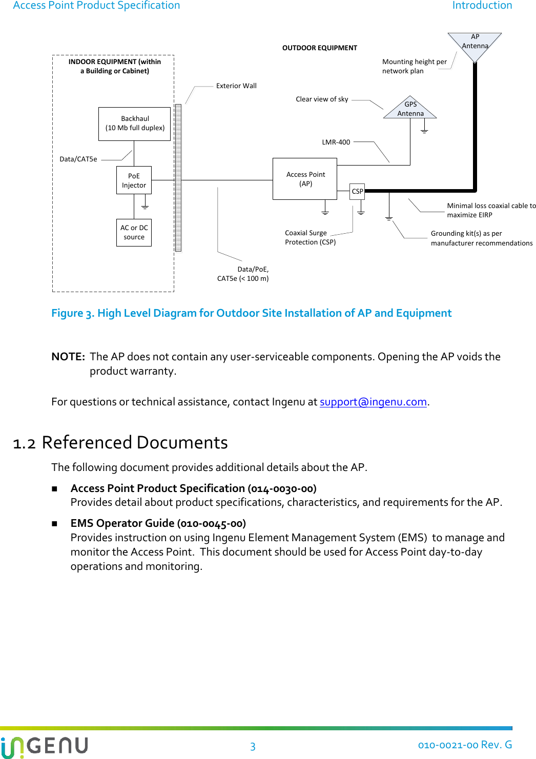
Ingenu ULPAP310 2.4GHz Spread Spectrum Device User Manual Access Point Product Specification
On-Ramp Wireless 2.4GHz Spread Spectrum Device Access Point Product Specification
Ingenu >
Contents
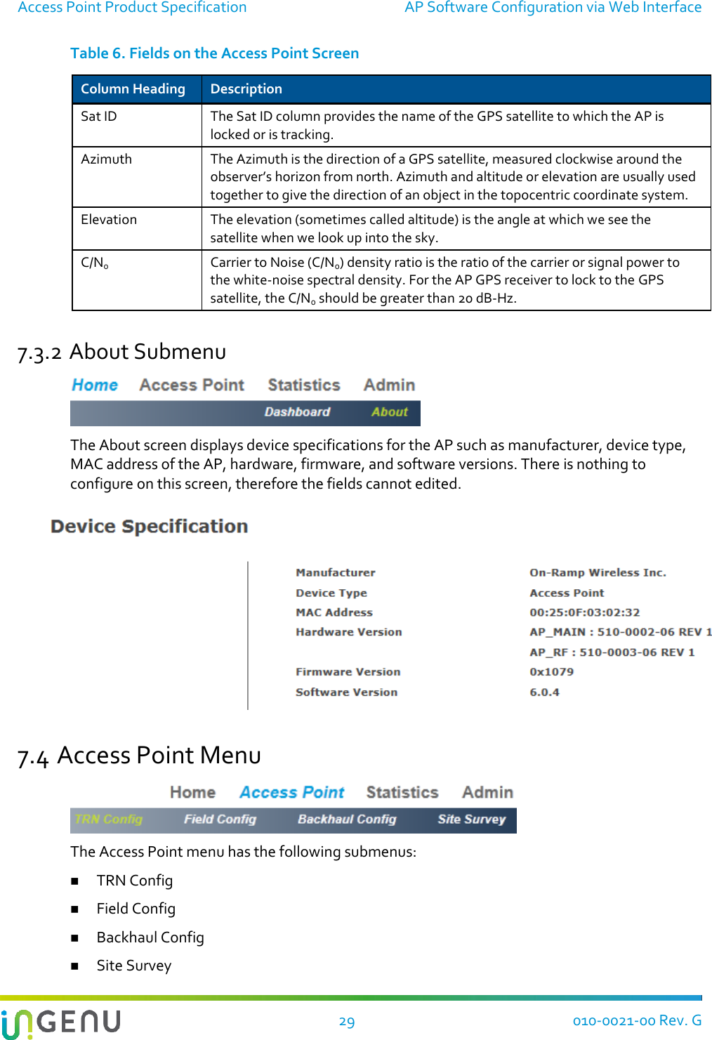
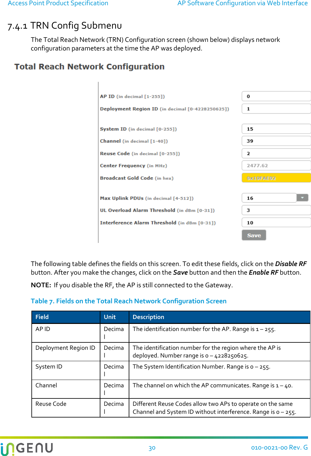
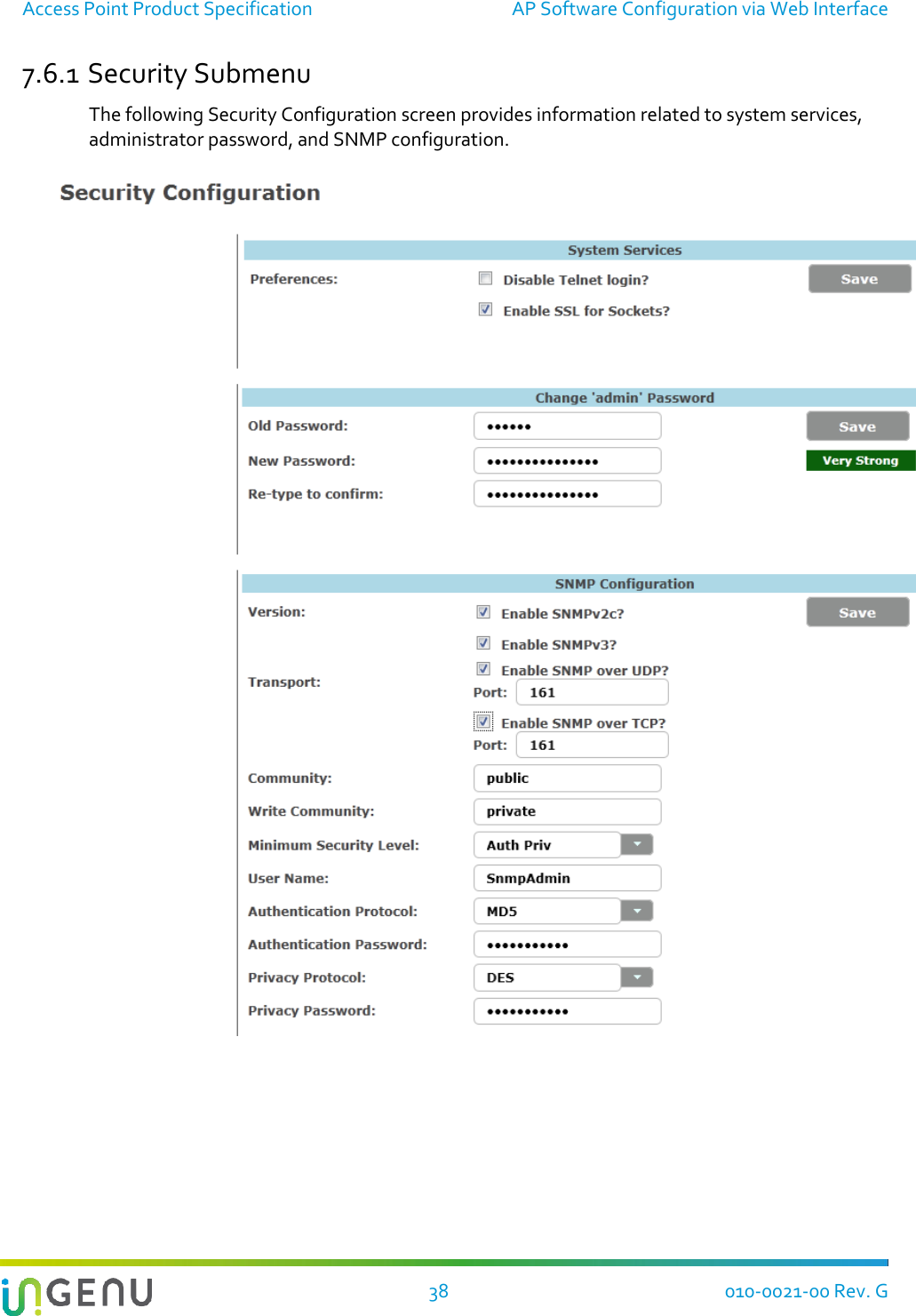
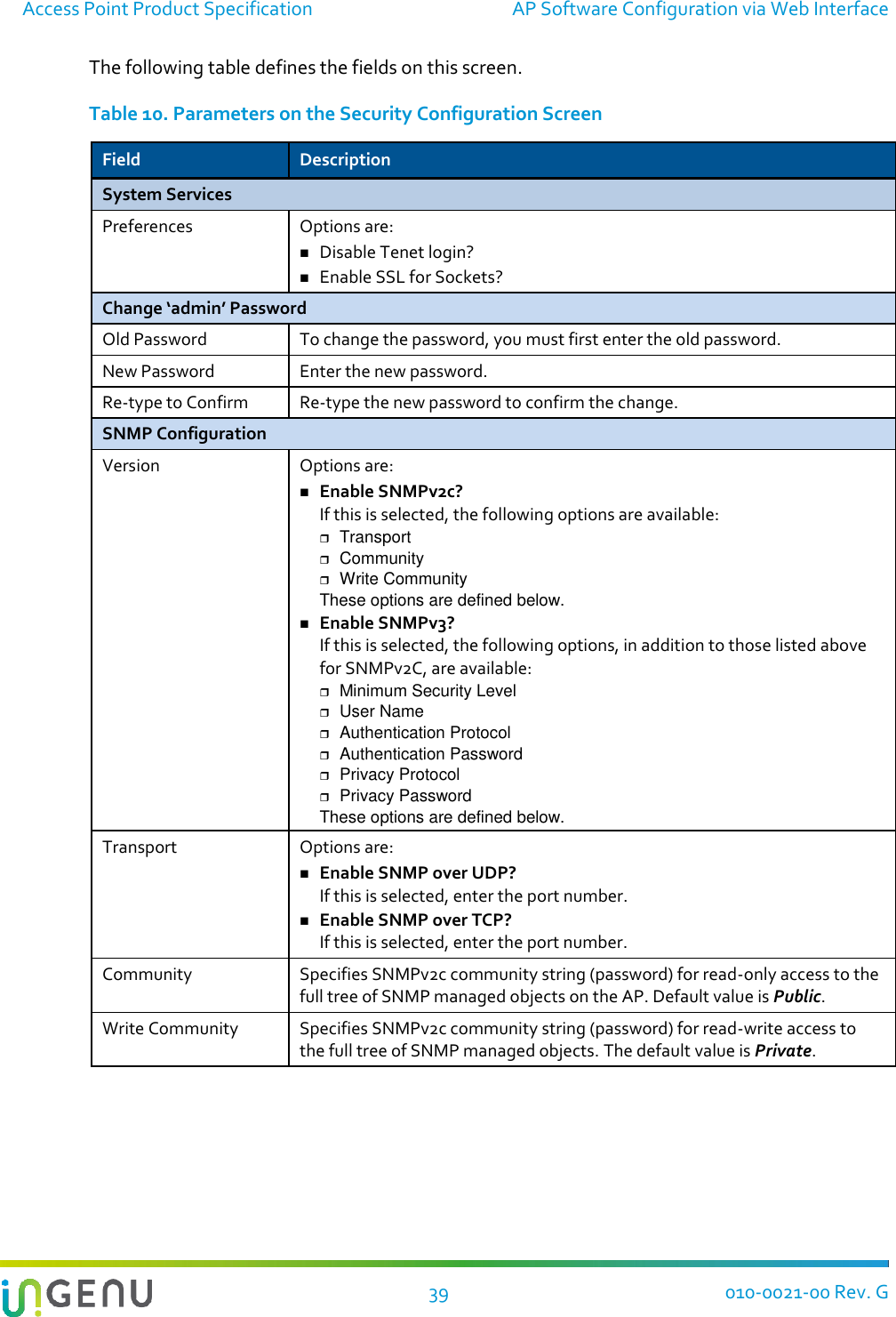
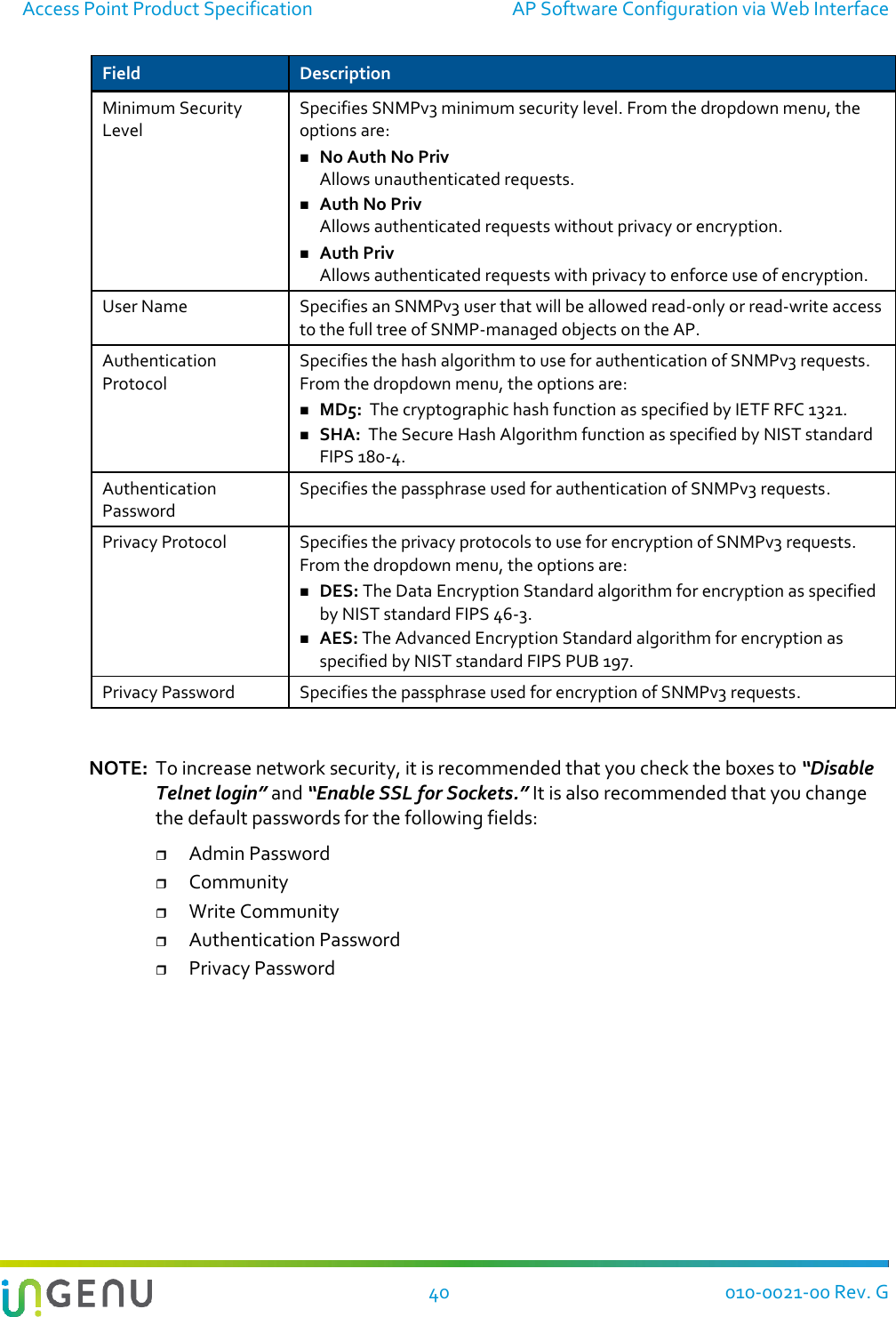
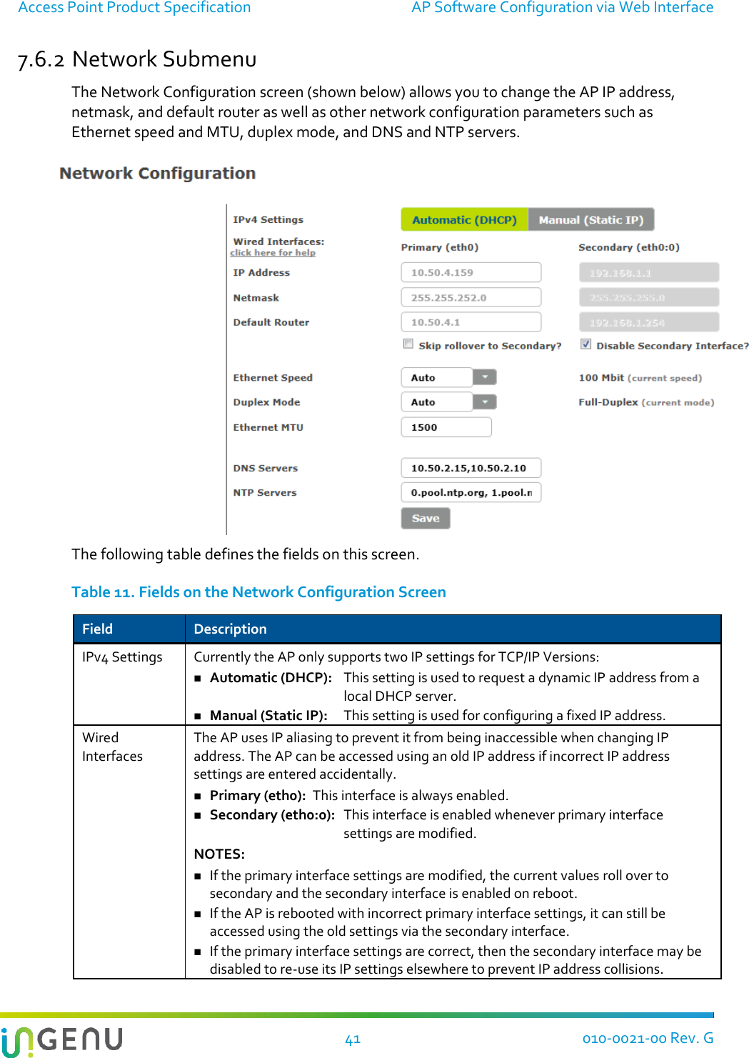
- 1. User Manual I
- 2. User Manual II
User Manual I