Ingenu ULPENODE100 On-Ramp Wireless eNode User Manual eNode User Manual 010 0002 00
On-Ramp Wireless On-Ramp Wireless eNode eNode User Manual 010 0002 00
Ingenu >
User Manual

DocumentNumber: 010‐0002‐00
Version:V1.1
Date:02/29/2010
TheinformationdisclosedinthisdocumentisproprietarytoOn‐RampWireless,andisnottobeused
ordisclosedtounauthorizedpersonswithoutthewrittenconsentofOn‐RampWireless.Therecipient
ofthisdocumentshallrespectthesecurityofthisdocumentandmaintaintheconfidentialityofthe
informationitcontains.Themastercopyofthisdocumentisstoredinelectronicformat,therefore
anyhardorsoftcopyusedfordistributionpurposesmustbeconsideredasuncontrolled.Reference
shouldbemadetoOn‐RampWirelesstoobtainthelatestversion.
Ultra‐LinkProcessing™
eNodeUserManual

eNodeUserManual‐010‐0002‐002
On‐RampWireless,Inc.
Document Control History
Version Date Author Remarks
1.0 2/12/10 ORW Initial Release
1.1 2/29/10 ORW Updated with certification comments (Sect 4.3 and 4.4)

eNodeUserManual‐010‐0002‐003
On‐RampWireless,Inc.
1 TABLEOFCONTENTS
1TABLEOFCONTENTS..............................................................................................................................3
1.1ListofFigures....................................................................................................................................................5
1.2ListofTables.....................................................................................................................................................5
2SCOPE............................................................................................................................................................6
2.1Whatdoesthisdocumentcover?......................................................................................................................6
2.2WhoshouldusethisManual?...........................................................................................................................6
2.3Referencedocuments.......................................................................................................................................6
3INTRODUCTION.........................................................................................................................................7
4APPROVALS................................................................................................................................................8
4.1FCC...................................................................................................................................................................8
4.2IndustryCanada................................................................................................................................................8
4.3Usage................................................................................................................................................................8
4.4Antennas..........................................................................................................................................................9
5ENODEOVERVIEWANDINTERFACES.............................................................................................10
5.1HardwareInterface.........................................................................................................................................10
5.1.1SPISlaveInterface.................................................................................................................................................10
5.1.2PinDescription......................................................................................................................................................11
5.1.3ElectricalCharacteristics.......................................................................................................................................12
5.1.4enodedimensions.................................................................................................................................................12
5.2SoftwareInterface..........................................................................................................................................13
5.3HostInterface.................................................................................................................................................13
5.3.1FunctionalDescription..........................................................................................................................................13
5.3.2HostInterfaceProtocol.........................................................................................................................................14
5.3.3SignalDescription.................................................................................................................................................14
5.3.4MasterRequest/SlaveReady..............................................................................................................................14
5.3.5SlaveRequest........................................................................................................................................................14
5.3.6OtherSignals.........................................................................................................................................................14
5.3.7SPIInterfaceDriver...............................................................................................................................................14
5.4SoftwareUpgradeProtocol.............................................................................................................................15

eNodeUserManual‐010‐0002‐004
On‐RampWireless,Inc.
5.4.1Overview...............................................................................................................................................................15
5.4.2Requirements........................................................................................................................................................15
5.5NotesandRecommendations..........................................................................................................................15

eNodeUserManual‐010‐0002‐005
On‐RampWireless,Inc.
1.1 LISTOFFIGURES
Figure1On‐RampWirelessULPNetwork...............................................................................................................................7
Figure2eNodeMechanicalDimensions................................................................................................................................12
Figure3eNodeSPIinterface..................................................................................................................................................13
1.2 LISTOFTABLES
Table1eNodePinDescription................................................................................................................................................11
Table2eNodeSPISignalDefinition........................................................................................................................................14

eNodeUserManual‐010‐0002‐006
On‐RampWireless,Inc.
2 SCOPE
2.1 WHATDOESTHISDOCUMENTCOVER?
ThisdocumentdescribestheOn‐RampWirelessUltra‐LinkProcessing™(ULP)eNode.Itdescribestheuseof
theeNodewithinaULPwirelesspacketdatanetworkandthehardwareandsoftwareinterfacesofthedevice.
2.2 WHOSHOULDUSETHISMANUAL?
CustomersintegratingOn‐Ramp’seNodemoduleintotheirsensorandlocationtrackingsystems,referredto
asHostsinthisdocument.ForadditionaldetailsonhostapplicationintegrationwiththeeNodepleasereferto
theeNodeSpecificationsandProgrammingGuide.
2.3 REFERENCEDOCUMENTS
eNodeUserManual‐010‐0002‐007
On‐RampWireless,Inc.
3 INTRODUCTION
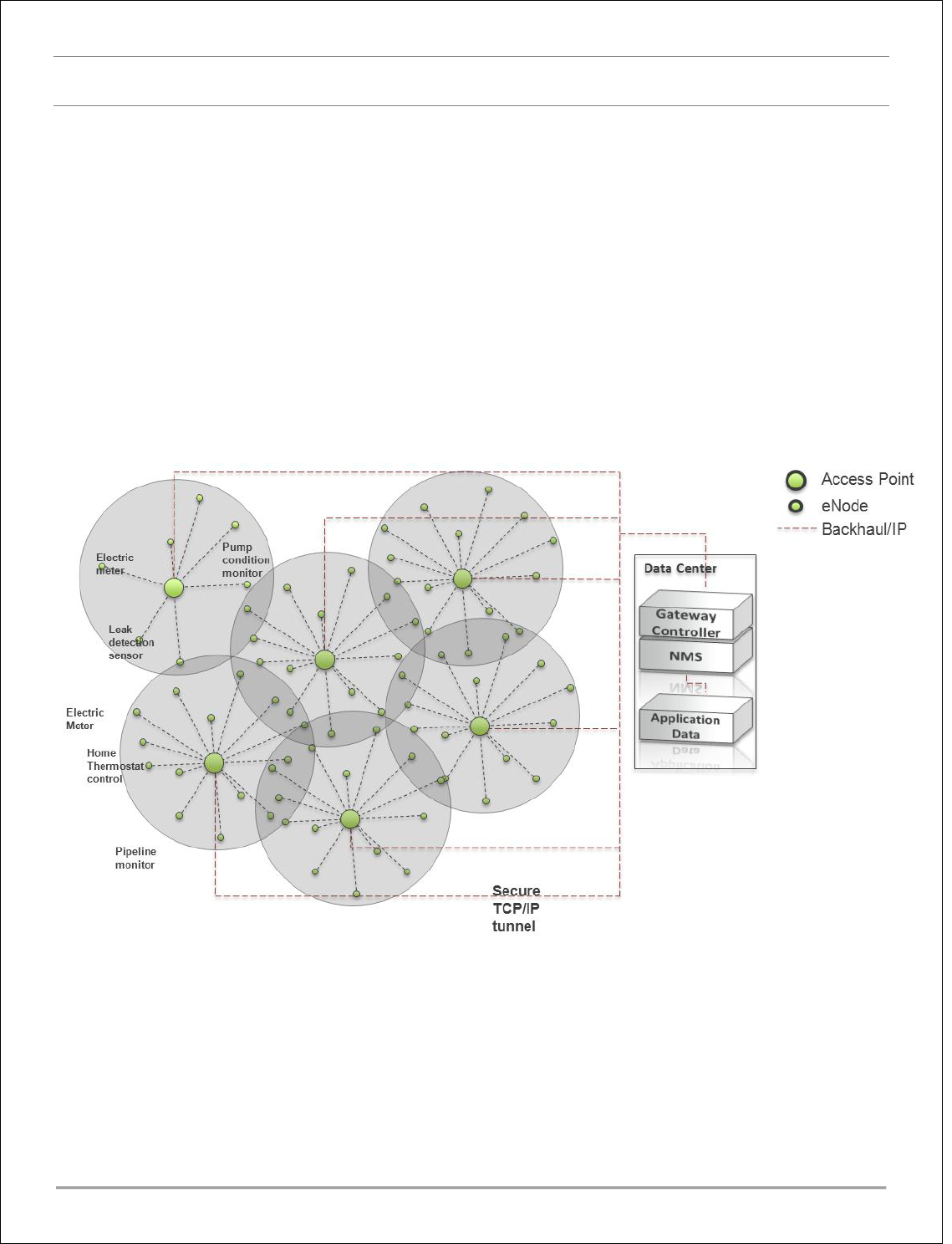
TheULPwirelesspacketdatanetwork,comprisedofeNodesandAccessPointsoperatesatabreakthrough
receivesensitivityof‐142dBm.Thisdramaticincreaseinreceivesensitivityallowsforawirelessrangeof2,000
milesinfreespaceand25xtherange(600xthecoverage)oftypicalwirelesssensorsystemswhilemaintaining
asmallandlow‐costformfactorwithmulti‐yearbatteryoperation.
TheULPeNodeisdesignedtoeasilyintegrate,viastandardinterfaces,withsensorsenablingrobustwireless
communicationwithoneormoreAccessPointsinterfacedwithacustomer’slocalorwideareanetwork.
EachAccessPointsupportstensofthousandsofsensorsandcansimultaneouslydemodulatesignalsfromup
toa1000sensorsusingauniquepatentedmultipleaccessscheme.With172dBoftotalallowablepathloss
(FCC/ICregulatoryregions)theULPnetworkcaneasilybedeployedusingastartopologyconfiguration,
overcomingthelimitationsoflegacywirelesssensornetworks(802.11,802.15.4,900MHzFHSS)thatrequire
complicatedmeshprotocolstoextendrangeoroperateinacapacitylimitedsimplexmode.
Figure1On‐RampWirelessULPNetwork

eNodeUserManual‐010‐0002‐008
On‐RampWireless,Inc.
4 APPROVALS
TheeNodehasbeendesignedtomeetregulationsforworld‐wideuse.
4.1 FCC
Thisdevicecomplieswithpart15oftheFCCRules.Operationissubjecttothefollowingtwoconditions:(1)
Thisdevicemaynotcauseharmfulinterference,and(2)thisdevicemustacceptanyinterferencereceived,
includinginterferencethatmaycauseundesiredoperation.
Changesormodificationsnotexpresslyapprovedbythemanufacturercouldvoidtheuser’sauthorityto
operatetheequipment.
Note:ThisequipmenthasbeentestedandfoundtocomplywiththelimitsforaClassBdigitaldevice,pursuant
toPart15oftheFCCRules.Theselimitsaredesignedtoprovidereasonableprotectionagainstharmful
interferenceinaresidentialinstallation.Thisequipmentgenerates,usesandcanradiateradiofrequency
energyand,ifnotinstalledandusedinaccordancewiththeinstructions,maycauseharmfulinterferenceto
radiocommunications.However,thereisnoguaranteethatinterferencewillnotoccurinaparticular
installation.Ifthisequipmentdoescauseharmfulinterferencetoradioortelevisionreception,whichcanbe
determinedbyturningtheequipmentoffandon,theuserisencouragedtotrytocorrecttheinterferenceby
oneormoreofthefollowingmeasures:
—Reorientorrelocatethereceivingantenna.
—Increasetheseparationbetweentheequipmentandreceiver.
—Connecttheequipmentintoanoutletonacircuitdifferentfromthattowhichthereceiverisconnected.
—Consultthedealeroranexperiencedradio/TVtechnicianforhelp.
4.2 INDUSTRYCANADA
Theinstallerofthisradioequipmentmustensurethattheantennaislocatedorpointedsuchthatitdoesnot
emitRFfieldinexcessofHealthCanadalimitsforthegeneralpopulation;consultSafetyCode6,obtainable
fromHeathCanada’swebsitewww.hc‐sc.gc.ca/rpb.
Operationissubjecttothefollowingtwoconditions:(1)thisdevicemaynotcauseinterference,and(2)this
devicemustacceptanyinterference,includinginterferencethatmaycauseundesiredoperationofthedevice.
Toreducepotentialradiointerferencetootherusers,theantennatypeanditsgainshouldbesochosenthat
theequivalentisotropicallyradiatedpower(e.i.r.p.)isnotmorethanthatpermittedforsuccessful
communication.
4.3 USAGE
FCCID:XTE‐ULPENODE100.IC:8655A‐ULPENODE100.Thisdeviceisonlyauthorizedforuseinmobile
applications.TomeetFCCandothernationalRFexposurerequirementstheantennaforthisdevicemustbe
installedtoensureaseparationdistanceofatleast20cm(8inches)fromtheantennatoaperson.

eNodeUserManual‐010‐0002‐009
On‐RampWireless,Inc.
4.4 ANTENNAS
Thisdevicehasbeendesignedtooperatewiththeantennaslistedbelow,andhavingamaximumgainof5dB.
Antennasnotincludedinthislistorhavingagaingreaterthan5dBarestrictlyprohibitedforusewiththis
device.Therequiredantennaimpedanceis50ohms.
5dBomni‐directionalantenna
2dBomni‐directionalantenna
1dBomni‐directionalantenna

eNodeUserManual‐010‐0002‐0010
On‐RampWireless,Inc.
5 ENODEOVERVIEWANDINTERFACES
TheeNodeplatformprovidesULPmodemfunctionalityontheclientside.TheeNodeplatformhandlesPHY&
MAClayers(L1andL2)fortheULPtechnology.TheeNodeplatformsupportsinterfacingoverSerialPeripheral
Interface(SPI).
TheeNodeeasilyintegrateswithSensororLocatingtrackingsystemusingthesoftwareandhardware
interfacessupported.TheeNodeactsastheslavedeviceandexpectsthehostboardtoactasmaster.
5.1 HARDWAREINTERFACE
5.1.1 SPISLAVEINTERFACE
TheSPISlaveeNodeInterfaceprovidescommunicationwithanexternalhostviaaserialperipheralinterface
(SPI).ThehostistheSPImasterandtheeNodeistheSPIslave.InadditiontothestandardSPIsignals,ahost‐
to‐nodewakeuprequest,anode‐to‐hoststatusandanode‐to‐hosttransmitrequestareincludedtosupport
eNodestatetransitionsandbi‐directionalmessagetraffic.

eNodeUserManual‐010‐0002‐0011
On‐RampWireless,Inc.
5.1.2 PINDESCRIPTION
Pin Name Pin # Pin Description Type Remark
Master Slave
SPI-MISO J701, 8 Master In Slave Out In Out SPI Bus data line in the direction of
slave to master.
SPI-MOSI J701, 7 Master Out Slave In Out In SPI Bus data line in the direction of
master to slave.
SPI-SCLK J701, 6 Serial Clock Out In SPI Bus clock driven by master.
Depending on how polarity and phase
are configured, this clock’s edges
indicate when the data on MISO and
MOSI are valid.
SPI-MRQ J703, 6 Master Request Out In Driven by the master to indicate to
slave that SPI activity needs to take
place. If the slave is sleeping, this signal
will wake it up. When the slave detects
this signal high, it must respond by
driving Slave Ready high.
SPI-SRDY J703, 7 Slave Ready In Out Driven by the slave to indicate to the
master that it is awake and ready to
perform SPI Bus transactions.
SPI-SRQ J703, 8 Slave Request In Out Driven by the slave to indicate that it
wishes to send a message over SPI Bus
to the master. This is necessary since
master drives the clock and this gives
the slave a way to inform the master
that the slave wishes the clock to be
driven.
SPI-CS0 J701, 5 SPI Chip Select Out In Used by Master to select which slave it
is communicating with over SPI Bus
RXD0 J701, 1 Serial 0 Receive Out In Reserved for future use.
TXD0 J701, 2 Serial 0 Transmit In Out Reserved for future use.
T_OUT J701, 3 TBD
RESET J701, 4 eNode Reset Out In Provides Host with ability to reset the
eNode.
RXD1 J703, 3 Serial 1 Receive Reserved for future use
TXD1 J703, 4 Serial 1 Transmit Reserved for future use
VBATT1 J703, 1
VBATT2 J703, 2
GND J701, 9
GND J701, 10
GND J703, 5
GND J703, 9
GND J703, 10
Table 1 eNodePinDescription
eNodeUserManual‐010‐0002‐0012
On‐RampWireless,Inc.
5.1.3 ELECTRICALCHARACTERISTICS
ModulesignalsaredefinedasCMOScompatible3Vlevels.Theactual3Vlevelscouldbebetween3.0V
and3.6V.
TheeNodeboardconvertstheinputvoltage(VBATT)toitsownrequiredvoltagelevels.Theinput
voltagerangeis2.4Vto5.5V.
Theboardcanconsumeuptotwo(2)wattsduringtransmission,itsmaximumpowermode.The
powersupplytotheeNodemustbeabletosupplyenoughcurrentatagivenoperatingvoltageto
providetwo(2)watts.
TheeNodeisspecifiedtooperateoveratemperaturerangeof‐40Cto+85Cambienttemperature.
SPIsignalsarepartofthe7‐wireSPIinterfacesystem
RX/TXArepartoftheUART.UARTDevicesarereservedforfutureuseforgeneralModem
communications.
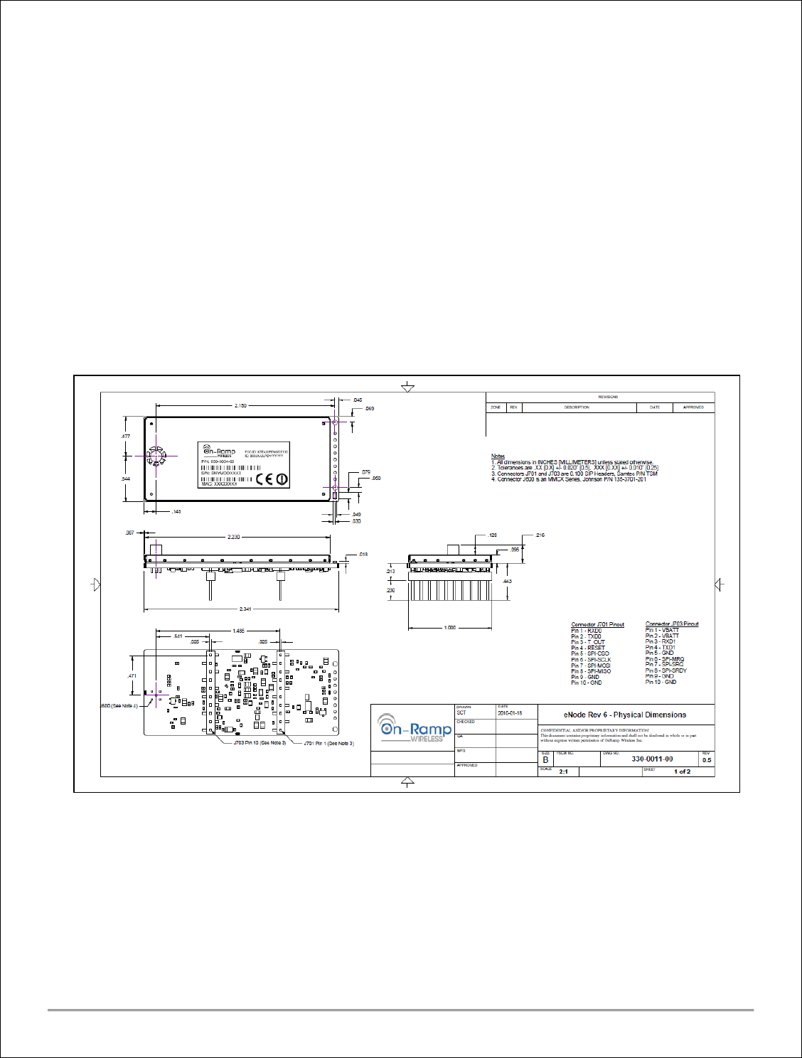
5.1.4 ENODEDIMENSIONS
The figure below shows the eNode dimensions.
Figure 2 eNode Mechanical Dimensions
eNodeUserManual‐010‐0002‐0013
On‐RampWireless,Inc.
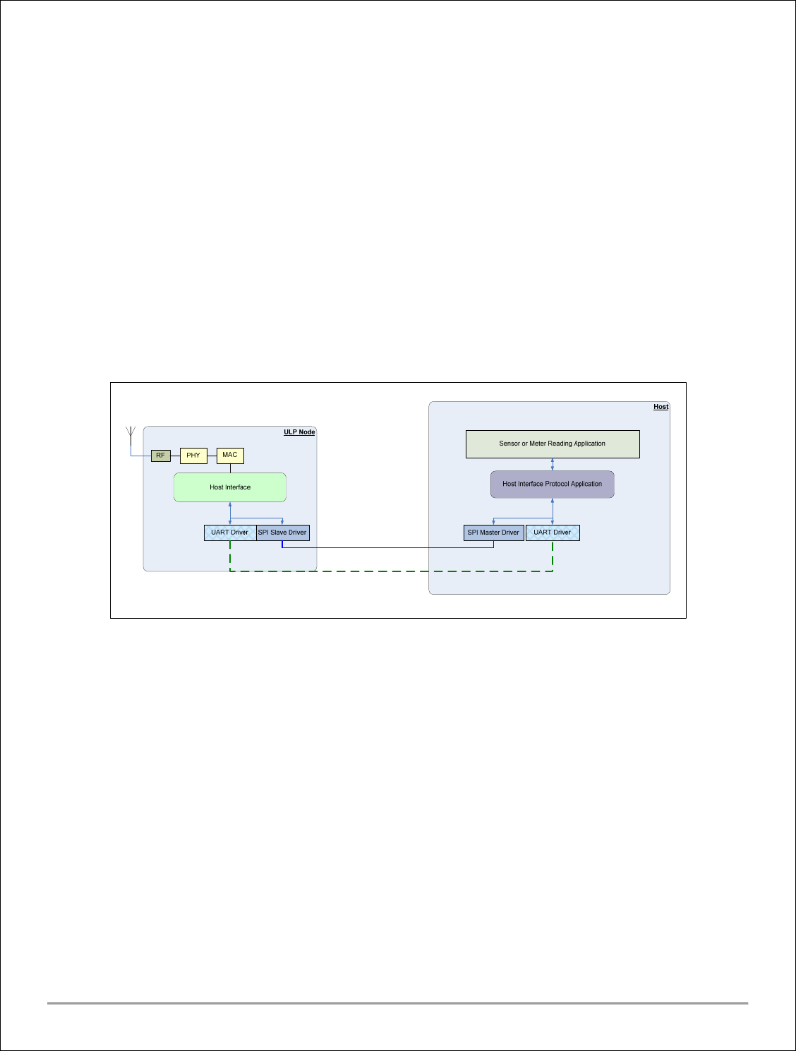
5.2 SOFTWAREINTERFACE
On‐Ramp’seNodeplatform’sSoftwareInterfaceincludesthenoderesidentSPIdriverfortheInterface
Hardwareandthenoderesidentmessagingapplication.Whilethedriverenablesthehardwarefordata
transfer,themessagingapplicationimplementsuserlevelmessageswhichenablethehosttocontrolthe
behaviorofthenode.UsingthesemessagesthehostcancontroltheeNodeallthewayfromintegrationto
deployment,includingcommissioningandconfiguration.
TheSPIdriverinitializesandmanagestheSPIhardware.TogetherwithSPIhardware,thedriverimplements
theSPIinterface.On‐Ramp’sSPIInterfacehasadditionalfeaturesthatsupportsleep&wake‐uprequests.
TheHostinterfaceprovidesfunctionalitydescribedinnextsection.Thehostinterfacelayerishardware
independentandcanrunonSPI.
Note:TheSPIMasterdriverandHostInterfaceProtocolapplicationonthehostneedtobedevelopedbythe
ownerofthe‘host’.TheyarenotprovidedbyOn‐Ramp.Somesamplecodeisavailable.
Figure 3 eNode SPI interface
5.3 HOSTINTERFACE
5.3.1 FUNCTIONALDESCRIPTION
Thehostinterfacesupportsthehigherlayermessagesfor:
CommissioningtheeNodefromtheHost
ConfiguringtheeNodefromtheHost
ControllingthestartupandsteadystatebehavioroftheeNode
TransferringpayloaddatatoandfromtheHost
UpgradingtheSoftwareontheeNode.[Futurereleases]
ExecutingasetofdiagnostictestsontheeNode.[Futurereleases]
CollectingdebugdatafromtheeNode.[Futurereleases]
ThemessagescanbebroadlyclassifiedasDebug,Configuration,andUserDatamessages.

eNodeUserManual‐010‐0002‐0014
On‐RampWireless,Inc.
5.3.2 HOSTINTERFACEPROTOCOL
On‐Ramp’sULPeNode’shostinterfacesupportsreliabletransferofmessagesbetweenthehostandeNode
overSPI.Tosupportthisfunctionality:
Explicit‘Connect’and‘Disconnect’messagesaresupported.
Eachhost‐to‐nodemessageisacknowledged.Thisisusefulinreliabilityandalsoforback‐pressure,
wherethehostneedstoslowdownorstopsendingmessagestotheeNode.Thenode‐to‐host
messagesdonothaveanyacknowledgements.TheeNodewillnotwaitforacknowledgements.The
eNodeexpectsthehosttobeabletoreceiveallmessagesandkeepupwiththeeNode.
FortheSPIinterface,thehost(beingtheSPImaster)isexpectedtobefastenoughsoastonotblock
variousoperationsattheeNode.Ifthisisviolated,theeNodewillmissRX/TXevents.
TheSPIDriverprovidesmethodsforbasicbit/bytetransport.TodothatthereareSPImessagerequests,SPI
messageheadersandSPIpayload.TheSPIpayloadcontainstheHostInterfacemessage.
5.3.3 SIGNALDESCRIPTION
PinNamePinDescription
Type
Master Slave
MISOMasterInSlaveOutInOut
MOSIMasterOutSlaveInOutIn
SCLKSerialClockOutIn
SSSlaveSelectOutIn
MRQMasterRequestOutIn
SRDYSlaveReadyInOut
SRQSlaveRequestInOut
Table 2 eNode SPI Signal Definition
5.3.4 MASTERREQUEST/SLAVEREADY
Beforeinitiatingtransferstoandfromthenode,thehostmustensurethenodeisawakeandreadytoreceive
SPItrafficbydrivingMRQhighandwaitingforthenodeSPIslavetodriveSRDYhigh.AhighlevelonMRQwill
wakeupasleepingnodeandwillpreventthenodefromgoingbacktosleep.
5.3.5 SLAVEREQUEST
Thenoderequestsamessagetransferfromnode‐to‐hostbydrivingtheSRQhigh.Hoststhatsupportbi‐
directionalSPItrafficrespondtoSRQbysendingamessagerequesttothenodeafterthecompletionofany
ongoingtransfers.
5.3.6 OTHERSIGNALS
Othersignalsi.e.MISO,MOSI,SCLK,SSareasperSPIStandard.
5.3.7 SPIINTERFACEDRIVER
ThenodeSPISlaveInterfacesoftwaredriverprovidesamessagingprotocolforinterfacingtoahostdevice
runninganOn‐RamphostSPImasterdriverandforinterfacingtoadevicerunningitsowndriver.

eNodeUserManual‐010‐0002‐0015
On‐RampWireless,Inc.
TheOn‐RamphostSPImasterdriverusesamessagingprotocolthatisactiveonlyafterthehosthascompleted
anarbitrationsequence.ThisallowsthenodetopasstrafficacrosstheSPIinterfacetobothahostandanon‐
hostdevice.
5.4 SOFTWAREUPGRADEPROTOCOL
5.4.1 OVERVIEW
ThenodesupportsupgradingofitssoftwareviathehostSPIinterface.Thismechanismallowsahostwhich
hasaccesstoanewsoftwareimagetotransfertheimagetoanattachednodeinsmallpiecesandhavethem
writtentoflash.Aftertheentireimagehasbeentransferredthenodeispoweredcycledtobootthenew
softwareimage.
5.4.2 REQUIREMENTS
Thenodemustbeintheidlestatewhenasoftwareupgradeisattempted.Thedurationofanupgradecycleis
dependentonthehostbutisatleast180seconds.
Powermustbemaintainedduringanupgradecycle.Powerlossduringanupgradecyclewillresultinanon‐
functionalnode.
5.5 NOTESANDRECOMMENDATIONS
o TheeNodeprocessorisbasedonARMandhenceLittleEndian.
o AttheSPIinterfacelevel
Arbitrationneedstobetypicallydoneatstartuptimeandafterexitingoutofdeepsleep
modes.Inadditiontothenormalcase,theeNodesupportsArbitrationat‐will.Whenthehost
initiatesarbitration,theeNodewillcomply.Thiscouldbeusedtoexitoutoferrorconditions.
eNodetoHostcommunicationtakespriorityoverHosttoeNode,astherearebufferwith
limitedsizesontheeNode.BufferoverflowscouldcauseunspecifiedresultsattheeNode.
WhenthereisaraceconditionbetweenHost‐to‐eNodeandeNode‐to‐Hostdatatransfer
initiation,thentheeNode‐to‐Hostisgivenpriority.ButifaHost‐to‐eNodetransferisin
progress,thentheeNodewillwaitforthetransfertocomplete.