Ingenu ULPENODE110 On-Ramp Wireless eNode User Manual eNode
On-Ramp Wireless On-Ramp Wireless eNode eNode
UserManual.wiki
>
Ingenu
>
ULPENODE110 User Manual
>
Users Manual
Contents
1.
Users Manual
2.
User Manual
Users Manual
Navigation menu
Upload a User Manual
Namespaces
Wiki Guide
HTML
PDF
Info
Views
User Manual
Discussion / Help
Navigation
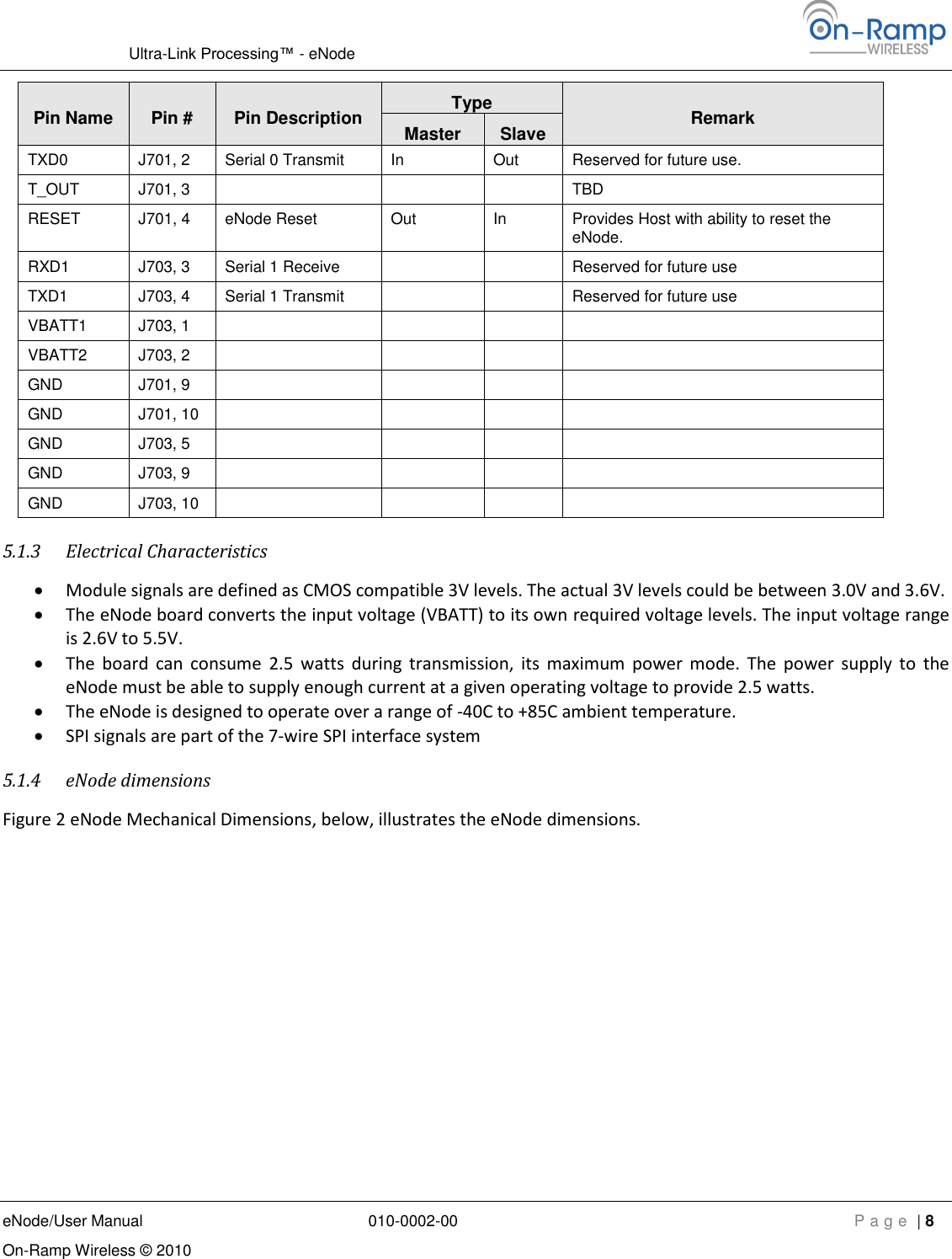
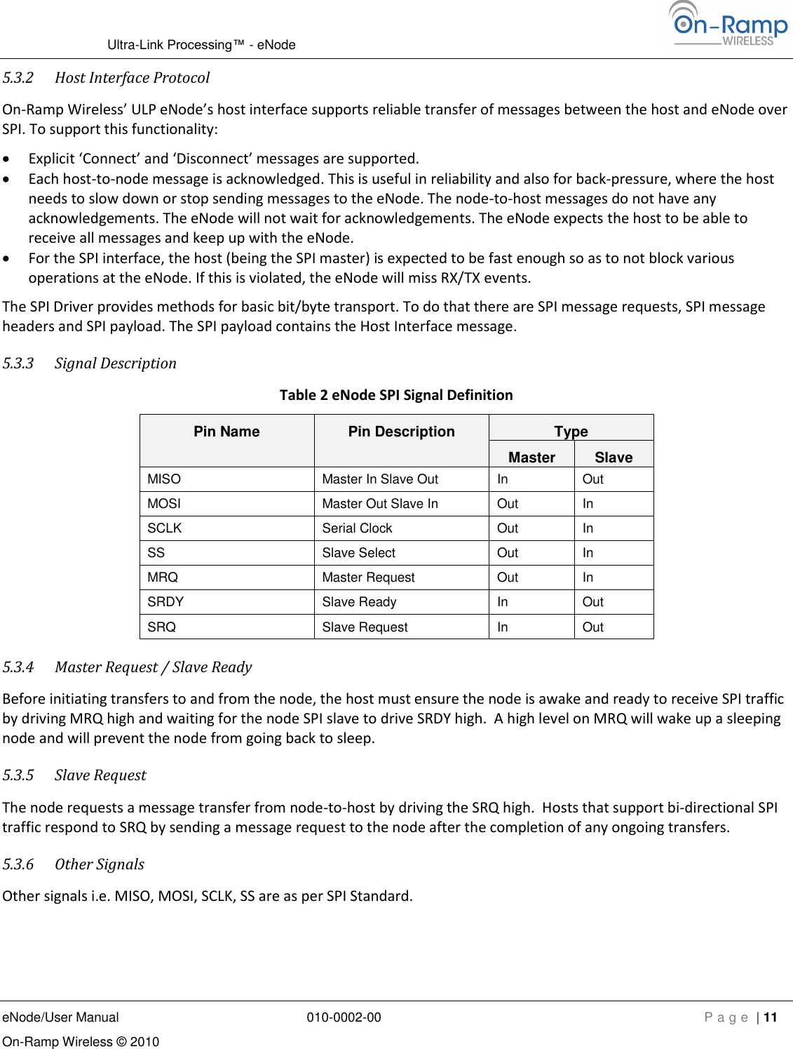
![Ultra-Link Processing™ - eNode eNode/User Manual 010-0002-00 P a g e | 10 On-Ramp Wireless © 2010 5.2 Software Interface On-Ramp Wireless’ eNode platform’s Software Interface includes the node resident SPI driver for the Interface Hardware and the node resident messaging application. While the driver enables the hardware for data transfer, the messaging application implements user level messages which enable the host to control the behavior of the node. Using these messages the host can control the eNode all the way from integration to deployment, including commissioning and configuration. The SPI driver initializes and manages the SPI hardware. Together with SPI hardware, the driver implements the SPI interface. On-Ramp Wireless’ SPI Interface has additional features that support sleep, and wake-up requests. The Host interface provides functionality described in next section. The host interface layer is hardware independent and can run on SPI. Note: The SPI Master driver and Host Interface Protocol application on the host need to be developed by the owner of the ‘host’. They are not provided by On-Ramp Wireless. Some sample code is available. ULP NodeHostSPI Slave DriverUART DriverHost InterfaceSPI Master Driver UART DriverHost Interface Protocol ApplicationSensor or Meter Reading ApplicationMACPHYRF Figure 3 eNode SPI interface 5.3 Host Interface 5.3.1 Functional Description The host interface supports the higher layer messages for: Commissioning the eNode from the Host Configuring the eNode from the Host Controlling the startup and steady state behavior of the eNode Transferring payload data to and from the Host Upgrading the Software on the eNode. [Future releases] Executing a set of diagnostic tests on the eNode. [Future releases] Collecting debug data from the eNode. [Future releases] The messages can be broadly classified as Debug, Configuration, and User Data messages.](https://usermanual.wiki/Ingenu/ULPENODE110.Users-Manual/User-Guide-1371683-Page-12.png)