Ingenu ULPENODE110 On-Ramp Wireless eNode User Manual eNode
On-Ramp Wireless On-Ramp Wireless eNode eNode
Ingenu >
Contents
- 1. Users Manual
- 2. User Manual
Users Manual
eNode
User Manual
010-0002-00
The information disclosed in this document is proprietary to On-Ramp Wireless, and is not to be used or disclosed to unauthorized persons without
the written consent of On-Ramp Wireless. The recipient of this document shall respect the security of this document and maintain the
confidentiality of the information it contains. The master copy of this document is stored in electronic format, therefore any hard or soft copy used
for distribution purposes must be considered as uncontrolled. Reference should be made to On-Ramp Wireless to obtain the latest version.

Ultra-Link Processing™ - eNode
eNode/User Manual 010-0002-00 P a g e | ii
On-Ramp Wireless © 2010
Document Control History
Version
Date
Author
Remarks
1.0
2/12/10
ORW
Initial Release
1.1
2/29/10
ORW
Updated with certification comments (Sect 4.3 and 4.4)
2.0
7/28/10
ORW
Updated for ULPENODE110
2.1
09/03/10
ORW
Updated max pwr consumption, input voltage range.
Removed UART statement. Updated formatting
3
09/16/10
ORW
Applied new formatting, modified footer to include copyright
statement.
4
11/04/10
ORW
Updated section 4.3 Usage, to include Integrators and RF
Exposure statements

Ultra-Link Processing™ - eNode
eNode/User Manual 010-0002-00 P a g e | 1
On-Ramp Wireless © 2010
Table of Contents
2 Scope ............................................................................................................................................................................... 3
2.1 What does this document cover? ........................................................................................................................... 3
2.2 Who should use this Manual? ................................................................................................................................. 3
2.3 Reference documents ............................................................................................................................................. 3
3 Introduction .................................................................................................................................................................... 4
4 Approvals ........................................................................................................................................................................ 5
4.1 FCC .......................................................................................................................................................................... 5
4.2 Industry Canada ...................................................................................................................................................... 5
4.3 Usage ....................................................................................................................................................................... 5
4.3.1 Integrators ....................................................................................................................................................... 6
4.3.2 RF Exposure Statement ................................................................................................................................... 6
4.4 Antennas ................................................................................................................................................................. 6
5 eNode Overview and Interfaces ..................................................................................................................................... 7
5.1 Hardware Interface ................................................................................................................................................. 7
5.1.1 SPI Slave Interface ........................................................................................................................................... 7
5.1.2 Pin Description ................................................................................................................................................ 7
5.1.3 Electrical Characteristics ................................................................................................................................. 8
5.1.4 eNode dimensions .......................................................................................................................................... 8
5.2 Software Interface ................................................................................................................................................ 10
5.3 Host Interface........................................................................................................................................................ 10
5.3.1 Functional Description .................................................................................................................................. 10
5.3.2 Host Interface Protocol ................................................................................................................................. 11
5.3.3 Signal Description .......................................................................................................................................... 11
5.3.4 Master Request / Slave Ready ...................................................................................................................... 11
5.3.5 Slave Request ................................................................................................................................................ 11
5.3.6 Other Signals ................................................................................................................................................. 11
5.3.7 SPI Interface Driver ....................................................................................................................................... 12
5.4 Software Upgrade Protocol................................................................................................................................... 12

Ultra-Link Processing™ - eNode
eNode/User Manual 010-0002-00 P a g e | 2
On-Ramp Wireless © 2010
5.4.1 Overview ....................................................................................................................................................... 12
5.4.2 Requirements ................................................................................................................................................ 12
5.5 Notes and Recommendations ............................................................................................................................... 12
Table of Figures
Figure 1 On-Ramp Wireless ULP Network ............................................................................................................................. 4
Figure 2 eNode Mechanical Dimensions ................................................................................................................................. 9
Figure 3 eNode SPI interface ................................................................................................................................................. 10
Table of Tables
Table 1 eNode Pin Description ................................................................................................................................................ 7
Table 2 eNode SPI Signal Definition ...................................................................................................................................... 11

Ultra-Link Processing™ - eNode
eNode/User Manual 010-0002-00 P a g e | 3
On-Ramp Wireless © 2010
2 Scope
2.1 What does this document cover?
This document describes On-Ramp Wireless’ Ultra-Link Processing™ (ULP) eNode. It describes the use of the eNode
within a ULP wireless packet data network and the hardware and software interfaces of the device.
2.2 Who should use this Manual?
Customers integrating On-Ramp Wireless’ eNode module into their sensor and location tracking systems (referred to as
Hosts in this document). For additional details on host application integration with the eNode, please refer to the eNode
Specifications and Programming Guide.
2.3 Reference documents
eNode Specifications and Programming Guide
Ultra-Link Processing™ - eNode
eNode/User Manual 010-0002-00 P a g e | 4
On-Ramp Wireless © 2010
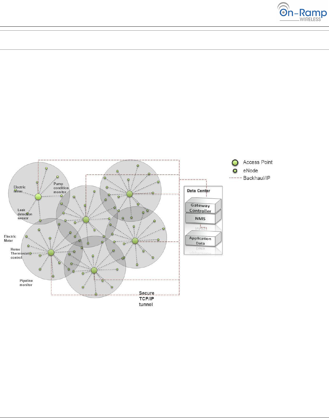
3 Introduction
The ULP wireless packet data network, comprised of eNodes and Access Points operates at a breakthrough receive
sensitivity of -142 dBm. This dramatic increase in receive sensitivity allows for a 2,000 mile wireless range in free space
and 25x the range (600x the coverage) of typical wireless sensor systems while maintaining a small and low-cost form
factor with multi-year battery operation.
The ULP eNode is designed to easily integrate, via standard interfaces, with sensors enabling robust wireless
communication with one or more Access Points interfaced with a customer’s local or wide area network.
Each Access Point supports tens of thousands of sensors and can simultaneously demodulate signals from up to a 1000
sensors using a unique patented multiple access scheme. With 172 dB of total allowable path loss (FCC/IC regulatory
regions) the ULP network can easily be deployed using a star topology configuration, overcoming the limitations of
legacy wireless sensor networks (802.11, 802.15.4, 900 MHz FHSS) that require complicated mesh protocols to extend
range or operate in a capacity limited simplex mode.
Figure 1 On-Ramp Wireless ULP Network

Ultra-Link Processing™ - eNode
eNode/User Manual 010-0002-00 P a g e | 5
On-Ramp Wireless © 2010
4 Approvals
The eNode has been designed to meet regulations for world-wide use.
4.1 FCC
This device complies with part 15 of the FCC Rules. Operation is subject to the following two conditions:
1. This device may not cause harmful interference
2. This device must accept any interference received, including interference that may cause undesired operation.
Changes or modifications not expressly approved by the manufacturer could void the user’s authority to operate the
equipment.
Note: This equipment has been tested and found to comply with the limits for a Class B digital device, pursuant to
Part 15 of the FCC Rules. These limits are designed to provide reasonable protection against harmful
interference in a residential installation. This equipment generates uses and can radiate radio frequency
energy and, if not installed and used in accordance with the instructions, may cause harmful interference to
radio communications. However, there is no guarantee that interference will not occur in a particular
installation. If this equipment does cause harmful interference to radio or television reception, which can be
determined by turning the equipment off and on, the user is encouraged to try to correct the interference
by one or more of the following measures:
Reorient or relocate the receiving antenna.
Increase the separation between the equipment and receiver.
Connect the equipment into an outlet on a circuit different from that to which the receiver is connected.
Consult the dealer or an experienced radio/TV technician for help.
4.2 Industry Canada
The installer of this radio equipment must ensure that the antenna is located or pointed such that it does not emit RF
field in excess of Health Canada limits for the general population; consult Safety Code 6, obtainable from Heath Canada’s
website www.hc-sc.gc.ca/rpb.
Operation is subject to the following two conditions:
1. This device may not cause interference, and
2. This device must accept any interference, including interference that may cause undesired operation of the device.
To reduce potential radio interference to other users, the antenna type and its gain should be so chosen that the
equivalent isotropically radiated power (e.i.r.p.) is not more than that permitted for successful communication.
4.3 Usage
FCC ID: XTE-ULPENODE110. IC: 8655A-ULPENODE110. This device is only authorized for use in portable applications. To
meet FCC and other national RF exposure requirements the antenna for this device must be installed to ensure a
separation distance of at least 20cm (8 inches) from the antenna to a person.

Ultra-Link Processing™ - eNode
eNode/User Manual 010-0002-00 P a g e | 6
On-Ramp Wireless © 2010
4.3.1 Integrators
A label showing the FCC ID and IC designators, listed above, must be affixed to the exterior of any device containing the
eNode (if the eNode is not visible). The exterior label must include: Contains FCC ID: XTE-ULPENODE110, IC 8655A-
ULPENODE110.
4.3.2 RF Exposure Statement
The air interface supports operation on channels in the 2402 MHz – 2476 MHz range for FCC/IC regulatory domains and
2402-2481 for the ETSI regulatory domain.
Before the ULP Node becomes operational it must undergo a commissioning procedure, during which critical
information required for operation is entered into the device and stored in non-volatile storage. It is during the initial
commissioning procedure that the regulatory domain under which the device will operate is set. Subsequent
configuration of the device during operation is checked against the commissioned regulatory domain and non-permitted
channels or transmit power levels are rejected and the device will not transmit until a permissible configuration per the
commissioned regulatory domain is set.
4.4 Antennas
This device has been designed to operate with the antennas listed below, and having a maximum gain of 5 dB. Antennas
not included in this list or having a gain greater than 5 dB are strictly prohibited for use with this device. The required
antenna impedance is 50 ohms.
5 dB omni-directional antenna
2 dB omni-directional antenna
1 dB omni-directional antenna

Ultra-Link Processing™ - eNode
eNode/User Manual 010-0002-00 P a g e | 7
On-Ramp Wireless © 2010
5 eNode Overview and Interfaces
The eNode platform provides ULP modem functionality on the client side. The eNode platform handles PHY & MAC
layers (L1 and L2) for the ULP technology. The eNode platform supports interfacing over Serial Peripheral Interface (SPI).
The eNode easily integrates with Sensor or Locating tracking system using the software and hardware interfaces
supported. The eNode acts as the slave device; the host board acts as master.
5.1 Hardware Interface
5.1.1 SPI Slave Interface
The SPI Slave eNode Interface provides communication with an external host via a serial peripheral interface (SPI). The
host is the SPI master and the eNode is the SPI slave. In addition to the standard SPI signals, a host-to-node wakeup
request, a node-to-host status and a node-to-host transmit request are included to support eNode state transitions and
bi-directional message traffic.
5.1.2 Pin Description
Table 1 eNode Pin Description
Pin Name
Pin #
Pin Description
Type
Remark
Master
Slave
SPI-MISO
J701, 8
Master In Slave Out
In
Out
SPI Bus data line in the direction of slave
to master.
SPI-MOSI
J701, 7
Master Out Slave In
Out
In
SPI Bus data line in the direction of master
to slave.
SPI-SCLK
J701, 6
Serial Clock
Out
In
SPI Bus clock driven by master.
Depending on how polarity and phase are
configured, this clock’s edges indicate
when the data on MISO and MOSI are
valid.
SPI-MRQ
J703, 6
Master Request
Out
In
Driven by the master to indicate to slave
that SPI activity needs to take place. If the
slave is sleeping, this signal will wake it up.
When the slave detects this signal high, it
must respond by driving Slave Ready high.
SPI-SRDY
J703, 7
Slave Ready
In
Out
Driven by the slave to indicate to the
master that it is awake and ready to
perform SPI Bus transactions.
SPI-SRQ
J703, 8
Slave Request
In
Out
Driven by the slave to indicate that it
wishes to send a message over SPI Bus to
the master. This is necessary since
master drives the clock and this gives the
slave a way to inform the master that the
slave wishes the clock to be driven.
SPI-CS0
J701, 5
SPI Chip Select
Out
In
Used by Master to select which slave it is
communicating with over SPI Bus
RXD0
J701, 1
Serial 0 Receive
Out
In
Reserved for future use.

Ultra-Link Processing™ - eNode
eNode/User Manual 010-0002-00 P a g e | 8
On-Ramp Wireless © 2010
Pin Name
Pin #
Pin Description
Type
Remark
Master
Slave
TXD0
J701, 2
Serial 0 Transmit
In
Out
Reserved for future use.
T_OUT
J701, 3
TBD
RESET
J701, 4
eNode Reset
Out
In
Provides Host with ability to reset the
eNode.
RXD1
J703, 3
Serial 1 Receive
Reserved for future use
TXD1
J703, 4
Serial 1 Transmit
Reserved for future use
VBATT1
J703, 1
VBATT2
J703, 2
GND
J701, 9
GND
J701, 10
GND
J703, 5
GND
J703, 9
GND
J703, 10
5.1.3 Electrical Characteristics
Module signals are defined as CMOS compatible 3V levels. The actual 3V levels could be between 3.0V and 3.6V.
The eNode board converts the input voltage (VBATT) to its own required voltage levels. The input voltage range
is 2.6V to 5.5V.
The board can consume 2.5 watts during transmission, its maximum power mode. The power supply to the
eNode must be able to supply enough current at a given operating voltage to provide 2.5 watts.
The eNode is designed to operate over a range of -40C to +85C ambient temperature.
SPI signals are part of the 7-wire SPI interface system
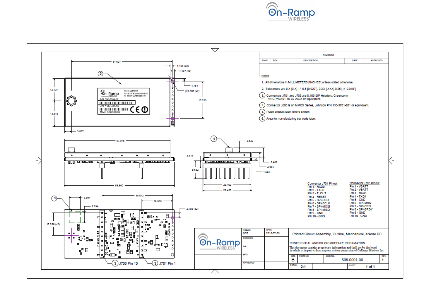
5.1.4 eNode dimensions
Figure 2 eNode Mechanical Dimensions, below, illustrates the eNode dimensions.
Ultra-Link Processing™ - eNode
eNode/User Manual 010-0002-00 P a g e | 9
On-Ramp Wireless © 2010
Figure 2 eNode Mechanical Dimensions
Ultra-Link Processing™ - eNode
eNode/User Manual 010-0002-00 P a g e | 10
On-Ramp Wireless © 2010
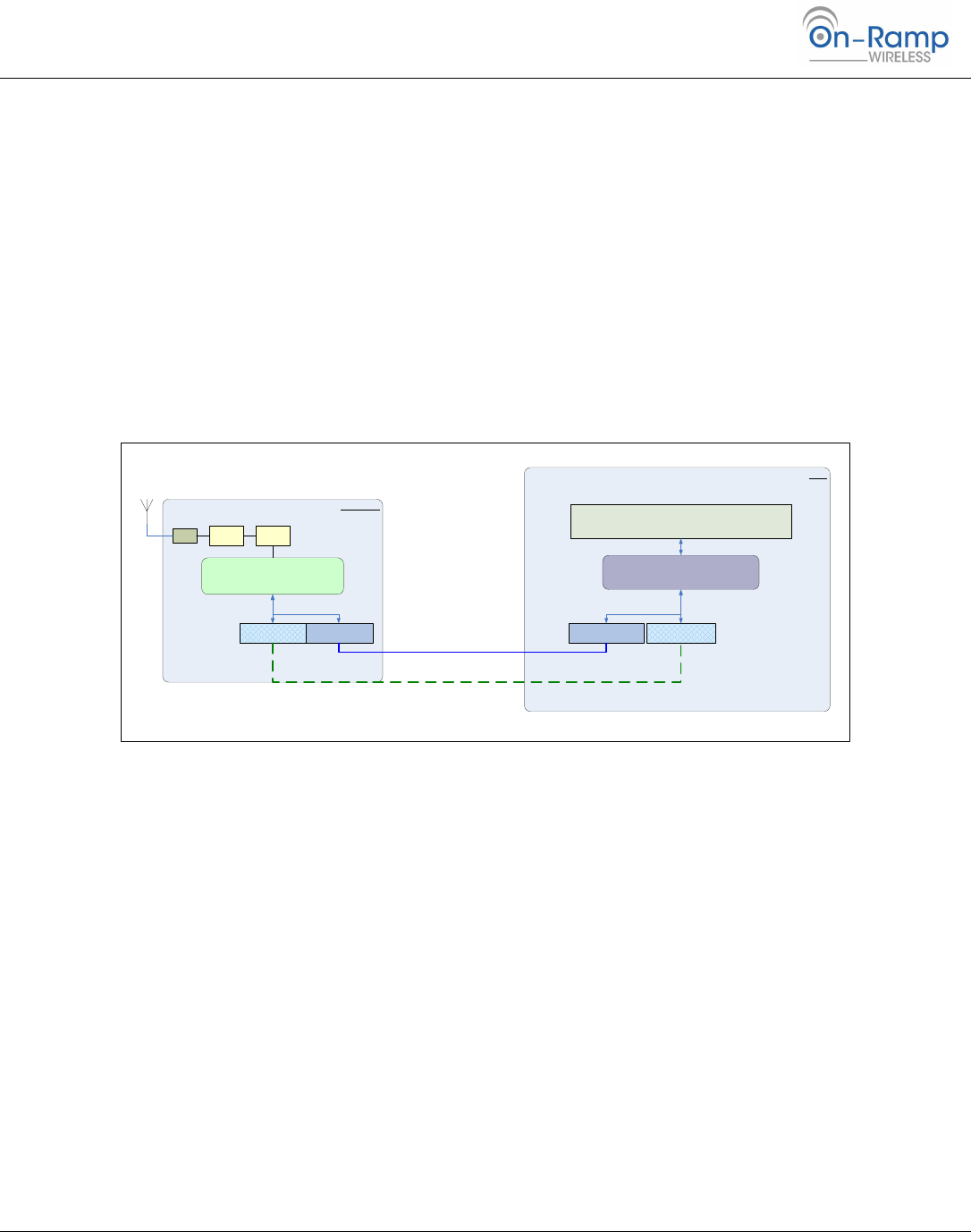
5.2 Software Interface
On-Ramp Wireless’ eNode platform’s Software Interface includes the node resident SPI driver for the Interface
Hardware and the node resident messaging application. While the driver enables the hardware for data transfer, the
messaging application implements user level messages which enable the host to control the behavior of the node. Using
these messages the host can control the eNode all the way from integration to deployment, including commissioning
and configuration.
The SPI driver initializes and manages the SPI hardware. Together with SPI hardware, the driver implements the SPI
interface. On-Ramp Wireless’ SPI Interface has additional features that support sleep, and wake-up requests.
The Host interface provides functionality described in next section. The host interface layer is hardware independent
and can run on SPI.
Note: The SPI Master driver and Host Interface Protocol application on the host need to be developed by the
owner of the ‘host’. They are not provided by On-Ramp Wireless. Some sample code is available.
ULP Node
Host
SPI Slave DriverUART Driver
Host Interface
SPI Master Driver UART Driver
Host Interface Protocol Application
Sensor or Meter Reading Application
MACPHYRF
Figure 3 eNode SPI interface
5.3 Host Interface
5.3.1 Functional Description
The host interface supports the higher layer messages for:
Commissioning the eNode from the Host
Configuring the eNode from the Host
Controlling the startup and steady state behavior of the eNode
Transferring payload data to and from the Host
Upgrading the Software on the eNode. [Future releases]
Executing a set of diagnostic tests on the eNode. [Future releases]
Collecting debug data from the eNode. [Future releases]
The messages can be broadly classified as Debug, Configuration, and User Data messages.

Ultra-Link Processing™ - eNode
eNode/User Manual 010-0002-00 P a g e | 11
On-Ramp Wireless © 2010
5.3.2 Host Interface Protocol
On-Ramp Wireless’ ULP eNode’s host interface supports reliable transfer of messages between the host and eNode over
SPI. To support this functionality:
Explicit ‘Connect’ and ‘Disconnect’ messages are supported.
Each host-to-node message is acknowledged. This is useful in reliability and also for back-pressure, where the host
needs to slow down or stop sending messages to the eNode. The node-to-host messages do not have any
acknowledgements. The eNode will not wait for acknowledgements. The eNode expects the host to be able to
receive all messages and keep up with the eNode.
For the SPI interface, the host (being the SPI master) is expected to be fast enough so as to not block various
operations at the eNode. If this is violated, the eNode will miss RX/TX events.
The SPI Driver provides methods for basic bit/byte transport. To do that there are SPI message requests, SPI message
headers and SPI payload. The SPI payload contains the Host Interface message.
5.3.3 Signal Description
Table 2 eNode SPI Signal Definition
Pin Name
Pin Description
Type
Master
Slave
MISO
Master In Slave Out
In
Out
MOSI
Master Out Slave In
Out
In
SCLK
Serial Clock
Out
In
SS
Slave Select
Out
In
MRQ
Master Request
Out
In
SRDY
Slave Ready
In
Out
SRQ
Slave Request
In
Out
5.3.4 Master Request / Slave Ready
Before initiating transfers to and from the node, the host must ensure the node is awake and ready to receive SPI traffic
by driving MRQ high and waiting for the node SPI slave to drive SRDY high. A high level on MRQ will wake up a sleeping
node and will prevent the node from going back to sleep.
5.3.5 Slave Request
The node requests a message transfer from node-to-host by driving the SRQ high. Hosts that support bi-directional SPI
traffic respond to SRQ by sending a message request to the node after the completion of any ongoing transfers.
5.3.6 Other Signals
Other signals i.e. MISO, MOSI, SCLK, SS are as per SPI Standard.

Ultra-Link Processing™ - eNode
eNode/User Manual 010-0002-00 P a g e | 12
On-Ramp Wireless © 2010
5.3.7 SPI Interface Driver
The node SPI Slave Interface software driver provides a messaging protocol for interfacing to a host device running an
On-Ramp Wireless host SPI master driver and for interfacing to a device running its own driver.
The On-Ramp Wireless host SPI master driver uses a messaging protocol that is active only after the host has completed
an arbitration sequence. This allows the node to pass traffic across the SPI interface to both a host and a non-host
device.
5.4 Software Upgrade Protocol
5.4.1 Overview
The node supports upgrading of its software via the host SPI interface. This mechanism allows a host which has access
to a new software image to transfer the image to an attached node in small pieces and have them written to flash. After
the entire image has been transferred the node is powered cycled to boot the new software image.
5.4.2 Requirements
The node must be in the idle state when a software upgrade is attempted. The duration of an upgrade cycle is
dependent on the host but is at least 180 seconds.
Power must be maintained during an upgrade cycle. Power loss during an upgrade cycle will result in a non-functional
node.
5.5 Notes and Recommendations
The eNode processor is based on ARM and hence Little Endian.
At the SPI interface level
Arbitration typically needs to be done at startup and after exiting from deep sleep modes. In addition to the
normal case, the eNode supports Arbitration at-will. When the host initiates arbitration, the eNode will comply.
This could be used to exit out of error conditions.
eNode to Host communication takes priority over Host to eNode, as there are buffer with limited sizes on the
eNode. Buffer over flows could cause unspecified results at the eNode. When there is a race condition between
Host-to-eNode and eNode-to-Host data transfer initiation, then the eNode-to-Host is given priority. But if a
Host-to-eNode transfer is in progress, then the eNode will wait for the transfer to complete.