Ingersoll Rand X41 Users Manual
X41 to the manual ce459541-88df-491f-bf03-f699d7296d8d
2015-01-23
: Ingersoll-Rand Ingersoll-Rand-X41-Users-Manual-342460 ingersoll-rand-x41-users-manual-342460 ingersoll-rand pdf
Open the PDF directly: View PDF ![]() .
.
Page Count: 85
- IR-PCB to IR Compressor Drawings.pdf
- X4I Overview Page 14�
- X4I Interconnect To Ingersoll Rand Unigy & Nirvana 20-40 HP Compressors Page 15�
- Unigy Phase 1 1of2 Page 16�
- Unigy Phase 1 2of2 Page 17�
- Unigy Phase 2/3 1of2 Page 18�
- Unigy Phase 2/3 2of2 Page 19�
- Nirvana 15 - 30KW (20-40HP) 1of2 Page 20�
- Nirvana 15 - 30KW (20-40HP) 2of2 Page 21�
- X4I Interconnect To Ingersoll Rand Intellisys Redeye Controlled Compressors Page 22�
- SSR Redeye 1of3 Page 23�
- SSR Redeye FV 2of3 Page 24�
- SSR Redeye SD 3of3 Page 25�
- X4I Interconnect To Ingersoll Rand Intellisys SE Controlled Compressors Page 26�
- SE UP 1of2 Page 27�
- SE UP 2of2 Page 28�
- SE ESA 1of2 Page 29�
- SE ESA 2of2 Page 30�
- SE DSA 1of2 Page 31�
- SE DSA 2of2 Page 32�
- X4I Interconnect To Ingersoll Rand Intellisys SG Controlled Compressors Page 33�
- SG SSR 1of2 Page 34�
- SG SSR 2of2 Page 35�
- SG Sierra 1of2 Page 36�
- SG Sierra 2of2 Page 37�
- X4I Interconnect To Ingersoll Rand Pressure Switch Controlled Compressors Page 38�
- SSR UP5 11-22 SD 1of2 Page 39�
- SSR UP5 11-22 SD 2of2 Page 40�
- SSR UP5 22-37 SD 1of2 Page 41�
- SSR UP5 22-37 SD 2of2 Page 42�
- SSR UP6 15-30 FV 1of2 Page 43�
- SSR UP6 15-30 FV 2of2 Page 44�
- SSR UP6 15-30 SD 1of2 Page 45�
- SSR UP6 15-30 SD 2of2 Page 46�
- SSR UP6 40-50 FV 1of2 Page 47�
- SSR UP6 40-50 FV 2of2 Page 48�
- SSR UP6 40-50 SD 1of2 Page 49�
- SSR UP6 40-50 SD 2of2 Page 50�
- UP6 5-15 FV 1PH 60Hz 1of2 Page 51�
- UP6 5-15 FV 1PH 60Hz 2of2 Page 52�
- UP6 5-15 FV 3PH 60Hz 1of2 Page 53�
- UP6 5-15 FV 3PH 60Hz 2of2 Page 54�
- UP6 5-15 SD 3PH 60Hz 1of2 Page 55�
- UP6 5-15 SD 3PH 60Hz 2of2 Page 56�
- UP6 5-15 FV 3PH 50Hz 1of2 Page 57�
- UP6 5-15 FV 3PH 50Hz 2of2 Page 58�
- UP6 5-15 SD 3PH 50Hz 1of2 Page 59�
- UP6 5-15 SD 3PH 50Hz 2of2 Page 60�
- SSR M15-22c 20-30HP XF EP HP HXP 50-60Hz 1of2 Page 61�
- SSR M15-22c 20-30HP XF EP HP HXP 50-60Hz 2of2 Page 62�
- M37-50 1of2 Page 63�
- M37-50 2of2 Page 64�
- EP 20-30 ESP FV 1of2 Page 65�
- EP 20-30 ESP FV 2of2 Page 66�
- EP 20-30 ESP SD 1of2 Page 67�
- EP 20-30 ESP SD 2of2 Page 68�
- X4I Interconnect To Ingersoll Rand Intellisys SGN / SGNe Controlled Compressors Page 69�
- Nirvana SGN/SGNe 1of3 Page 70�
- Nirvana SGN/SGNe 2of3 Page 71�
- Nirvana SGN/SGNe 3of3 Page 72�
- SI1 Interface to Redeye, SE, SG Controllers Page 73�
- X4I Interconnect To Ingersoll Rand Intellisys S3 Page 74�
- Intellisys S3 1of2 Page 75�
- Intellisys S3 2of2 Page 76�
- X4I Interconnect to Ingersoll Rand Small Reciprocating Air Compressors Page 77�
- UP6RE 7.5–15 175, UP6RX 7.5–15 175 1of3 Page 78�
- UP6RE 7.5–15 175, UP6RX 7.5–15 175 2of3 Page 79�
- UP6RE 7.5–15 175, UP6RX 7.5–15 175 3of3 Page 80�
- Models 2340, 2475, 2545, 7100, 15T & 3000 10f3 Page 81 �
- Models 2340, 2475, 2545, 7100, 15T & 3000 2of3 Page 82�
- Models 2340, 2475, 2545, 7100, 15T & 3000 3of3 Page 83�
- Excessive Pressure Shutdown Switch Example Before Installation Page 84�
- Excessive Pressure Shutdown Switch Example After Installation Page 85�

Ingersoll Rand
System Automation X4I
Application & Compressor Interconnect Guide
More Than Air. Answers.
Online answers: http://www.air.irco.com
Before installing or starting this unit for the first
time, this manual should be studied carefully to
obtain a working knowledge of the unit and/or the
duties to be performed while operating and
maintaining the unit.
RETAIN THIS MANUAL WITH UNIT. This Technical
manual contains IMPORTANT SAFETY DATA and
should be kept with the unit at all times.
C.C.N. : 80443864
REV. : A
DATE : APRIL 2007

2
SECTION 1 — TABLE OF CONTENTS
SECTION 1 — TABLE OF CONTENTS................................ 2
SECTION 2 — INTRODUCTION........................................ 4
SECTION 3 — SAFETY..................................................... 4
INSTALLATION ............................................................... 4
OPERATION.................................................................... 4
MAINTENANCE AND REPAIR ........................................... 4
SECTION 4 — INSTALLATION ......................................... 6
Unit Location ................................................................. 6
Power Supply ................................................................. 7
Pressure Sensor Location ............................................... 7
SUPPLY (WET) Side Pressure Control ........................ 7
DEMAND (DRY) Side Pressure Control ...................... 7
Pressure Sensor Connection........................................... 8
IR-PCB Interface Module ................................................. 8
Input Functions.............................................................. 9
Ready Input ............................................................. 9
Ready Input, Alternative Connection Method ........... 9
Run Input .............................................................. 10
Warning Input (optional)........................................ 10
Output Functions ......................................................... 11
Pressure Switch Regulation.................................... 11
Digital Regulation Control Terminal C01 ............... 11
Service Maintenance Switch ................................... 12
Auxiliary Input (Option) ......................................... 12
Auxiliary Output (Option) ...................................... 13
RS485 Communications ........................................ 13
SECTION 5 — ASSISTANCE ........................................... 13
SECTION 6 — X4I Overview and Interconnect Drawings 13
X4I Overview................................................................ 11
X4I Interconnect To Ingersoll Rand Unigy &
Nirvana 15 - 30KW (20-40HP) Compressors ................. 15
Unigy 1 1of2 ......................................................... 11
Unigy 1 2of2 ......................................................... 11
Unigy 2/3 1of2...................................................... 11
Unigy 2/3 2of2...................................................... 11
Nirvana 15 - 30KW (20-40HP) 1of2 ........................ 20
Nirvana 15 - 30KW (20-40HP) 2of2 ........................ 21
X4I Interconnect To Ingersoll Rand Intellisys Redeye
Controlled Compressors ...............................................22
SSR Redeye 1of3.....................................................23
SSR Redeye FV 2of3................................................24
SSR Redeye SD 3of3 ...............................................25
X4I Interconnect To Ingersoll Rand Intellisys SE
Controlled Compressors ...............................................26
SE UP 1of2..............................................................27
SE UP 2of2..............................................................28
SE ESA 1of2 ............................................................29
SE ESA 2of2 ............................................................30
SE DSA 1of2 ...........................................................31
SE DSA 2of2 ...........................................................32
X4I Interconnect To Ingersoll Rand Intellisys SG
Controlled Compressors ...............................................33
SG SSR 1of2............................................................34
SG SSR 2of2............................................................35
SG Sierra 1of2 ........................................................36
SG Sierra 2of2 ........................................................37
X4I Interconnect To Ingersoll Rand Pressure Switch
Controlled Compressors ...............................................38
SSR UP5 11-22 SD 1of2 ..........................................39
SSR UP5 11-22 SD 2of2 ..........................................40
SSR UP5 22-37 SD 1of2 ..........................................41
SSR UP5 22-37 SD 2of2 ..........................................42
SSR UP6 15-30 FV 1of2...........................................43
SSR UP6 15-30 FV 2of2...........................................44
SSR UP6 15-30 SD 1of2 ..........................................45
SSR UP6 15-30 SD 2of2 ..........................................46
SSR UP6 40-50 FV 1of2...........................................47
SSR UP6 40-50 FV 2of2...........................................48
SSR UP6 40-50 SD 1of2 ..........................................49
SSR UP6 40-50 SD 2of2 ..........................................50
UP6 5-15 FV 1PH 60Hz 1of2...................................51
UP6 5-15 FV 1PH 60Hz 2of2...................................52
UP6 5-15 FV 3PH 60Hz 1of2...................................53
UP6 5-15 FV 3PH 60Hz 2of2...................................54
UP6 5-15 SD 3PH 60Hz 1of2 ..................................55
UP6 5-15 SD 3PH 60Hz 2of2 ..................................56
UP6 5-15 FV 3PH 50Hz 1of2...................................57
UP6 5-15 FV 3PH 50Hz 2of2...................................58
www.air.irco.com X4I System Automation
3
X4I Interconnect To Ingersoll Rand Pressure Switch
Controlled Compressors .................................. Continued
UP6 5-15 SD 3PH 50Hz 1of2.................................. 59
UP6 5-15 SD 3PH 50Hz 2of2.................................. 60
SSR M15-22c 20-30HP XF EP HP HXP
50-60Hz 1of2 ........................................................ 61
SSR M15-22c 20-30HP XF EP HP HXP
50-60Hz 2of2 ........................................................ 62
M37-50 1of2 ......................................................... 64
M37-50 2of2 ......................................................... 65
EP 20-30 ESP FV 1of2............................................. 66
EP 20-30 ESP FV 2of2............................................. 67
EP 20-30 ESP SD 1of2 ............................................ 68
EP 20-30 ESP SD 2of2 ............................................ 69
X4I Interconnect To Ingersoll Rand Intellisys SGN / SGNe
Controlled Compressors .............................................. 70
Nirvana SGN/SGNe 1of3 ........................................ 71
Nirvana SGN/SGNe 2of3 ........................................ 72
Nirvana SGN/SGNe 3of3 ........................................ 73
SI1 Interface to Redeye, SE, SG Controllers ............ 73
X4I Interconnect To Ingersoll Rand Intellisys S3 ........... 74
Intellisys S3 1of2 ................................................... 75
Intellisys S3 2of2 ................................................... 76
X4I Interconnect to Ingersoll Rand Small Reciprocating
Air Compressors ......................................................... 77
UP6RE 7.5–15 175, UP6RX 7.5–15 175 1of3 .......... 78
UP6RE 7.5–15 175, UP6RX 7.5–15 175 2of3 .......... 79
UP6RE 7.5–15 175, UP6RX 7.5–15 175 3of3 .......... 80
Models 2340, 2475, 2545, 7100,
15T & 3000 10f3................................................... 81
Models 2340, 2475, 2545, 7100,
15T & 3000 20f3................................................... 82
Models 2340, 2475, 2545, 7100,
15T & 3000 30f3................................................... 83
Excessive Pressure Shutdown Switch Example Before
Installation .................................................................. 84
Excessive Pressure Shutdown Switch Example After
Installation .................................................................. 85
www.air.irco.com X4I System Automation
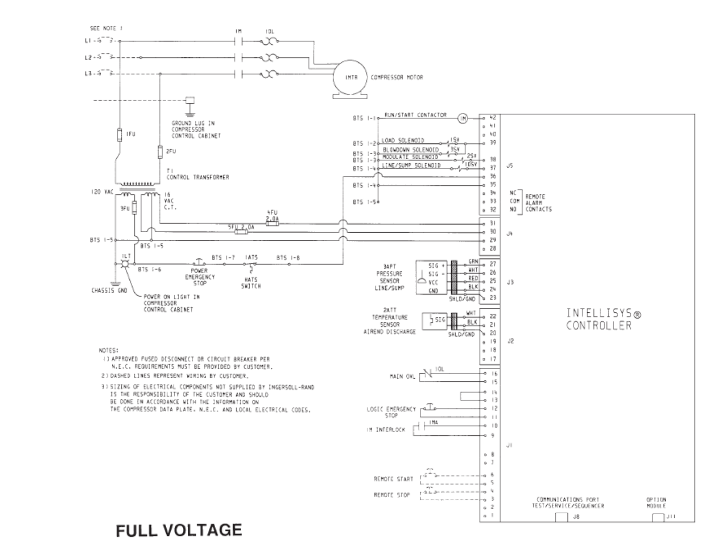
SECTION 2 — INTRODUCTION
The X4I is a specialized controller designed to provide
safe, reliable, and energy-efficient control of your
compressed air system. The X4I is capable of controlling
up to four positive displacement air compressors. The
compressors may have electro-pneumatic or
microprocessor based controls. The X4I is completely
customizable to meet the specific needs of your
compressed air system.
SECTION 3 — SAFETY
!
!
WARNING : Risk of Danger
WARNING : Risk of Electric Shock
WARNING : Risk of High Pressure
WARNING : Consult Manual
4
• Before installing or operating the X4I,
take time to carefully read all the
instructions contained in this manual, all
compressor manuals, and all manuals of
any other peripheral devices that may be
installed or connected to the unit.
• Electricity and compressed air have the
potential to cause severe personal injury
or property damage.
• The operator should use common sense
and good working practices while
operating and maintaining this system.
All applicable codes should be strictly
adhered to.
• Maintenance must be performed by
adequately qualified personnel that are
equipped with the proper tools.
INSTALLATION
• Installation work must only be carried
out by a competent person under
qualified supervision.
• A fused isolation switch must be fitted
between the main power supply and the
X4I.
• The X4I should be mounted in such a
location as to allow operational and
maintenance access without obstruction
or hazard and to allow clear visibility of
indicators at all times.
• If raised platforms are required to
provide access to the X4I, they must not
interfere with normal operation or
obstruct access. Platforms and stairs
should be of grid or plate construction
with safety rails on all open sides.
OPERATION
• The X4I must only be operated by
competent personnel under qualified
supervision.
• Never remove or tamper with safety
devices, guards or insulation materials
fitted to the X4I.
• The X4I must only be operated at the
supply voltage and frequency for which
it is designed.
• When main power is switched on, lethal
voltages are present in the electrical
circuits and extreme caution must be
exercised whenever it is necessary to
carry out any work on the unit.
• Do not open access panels or touch
electrical components while voltage is
applied unless it is necessary for
measurements, tests or adjustments.
Such work should be carried out only by
a qualified electrician equipped with the
correct tools and wearing appropriate
protection against electrical hazards.
• All air compressors and/or other
equipment connected to the unit should
have a warning sign attached stating
“THIS UNIT MAY START WITHOUT
WARNING” next to the display panel.
• If an air compressor and/or other
equipment connected to the unit is to be
started remotely, attach two warning
signs to the equipment stating “THIS
UNIT CAN BE STARTED REMOTELY”.
Attach one sign in a prominent location
on the outside of the equipment, and
the other sign inside the equipment
control compartment.
MAINTENANCE AND REPAIR
• Maintenance, repairs or modifications
must only be carried out by competent
personnel under qualified supervision.
• If replacement parts are required, use
only genuine parts from the original
equipment manufacturer, or an
alternative approved source.
www.air.irco.com X4I System Automation
5
• Carry out the following operations
before opening or removing any access
panels or carrying out any work on the
X4I:
i. Isolate the X4I from the main
electrical power supply. Lock the
isolator in the “OFF” position
and remove the fuses.
ii. Attach labels to the isolator
switch and to the unit stating
“WORK IN PROGRESS - DO NOT
APPLY VOLTAGE”. Do not switch
on electrical power or attempt to
start the X4I if such a warning
label is attached.
• Make sure that all instructions
concerning operation and maintenance
are strictly followed and that the
complete unit, with all accessories and
safety devices, is kept in good working
order.
• The accuracy of sensor devices must be
checked on a regular basis. They must
be calibrated when acceptable tolerances
are exceeded. Always ensure any
pressure within the compressed air
system is safely vented to atmosphere
before attempting to remove or install a
sensor device.
• The X4I must only be cleaned with a
damp cloth, using mild detergents if
necessary. Avoid the use of any
substances containing corrosive acids or
alkalis.
• Do not paint the control faceplate or
obscure any indicators, controls,
instructions or warnings.
www.air.irco.com X4I System Automation
SECTION 4 — INSTALLATION
It is recommended that installation and commissioning
be carried out by an authorized and trained product
supplier.
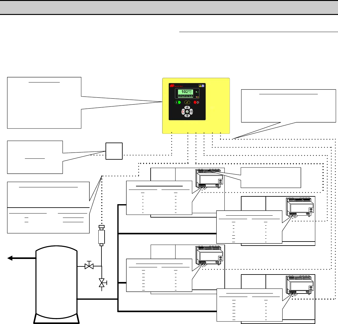
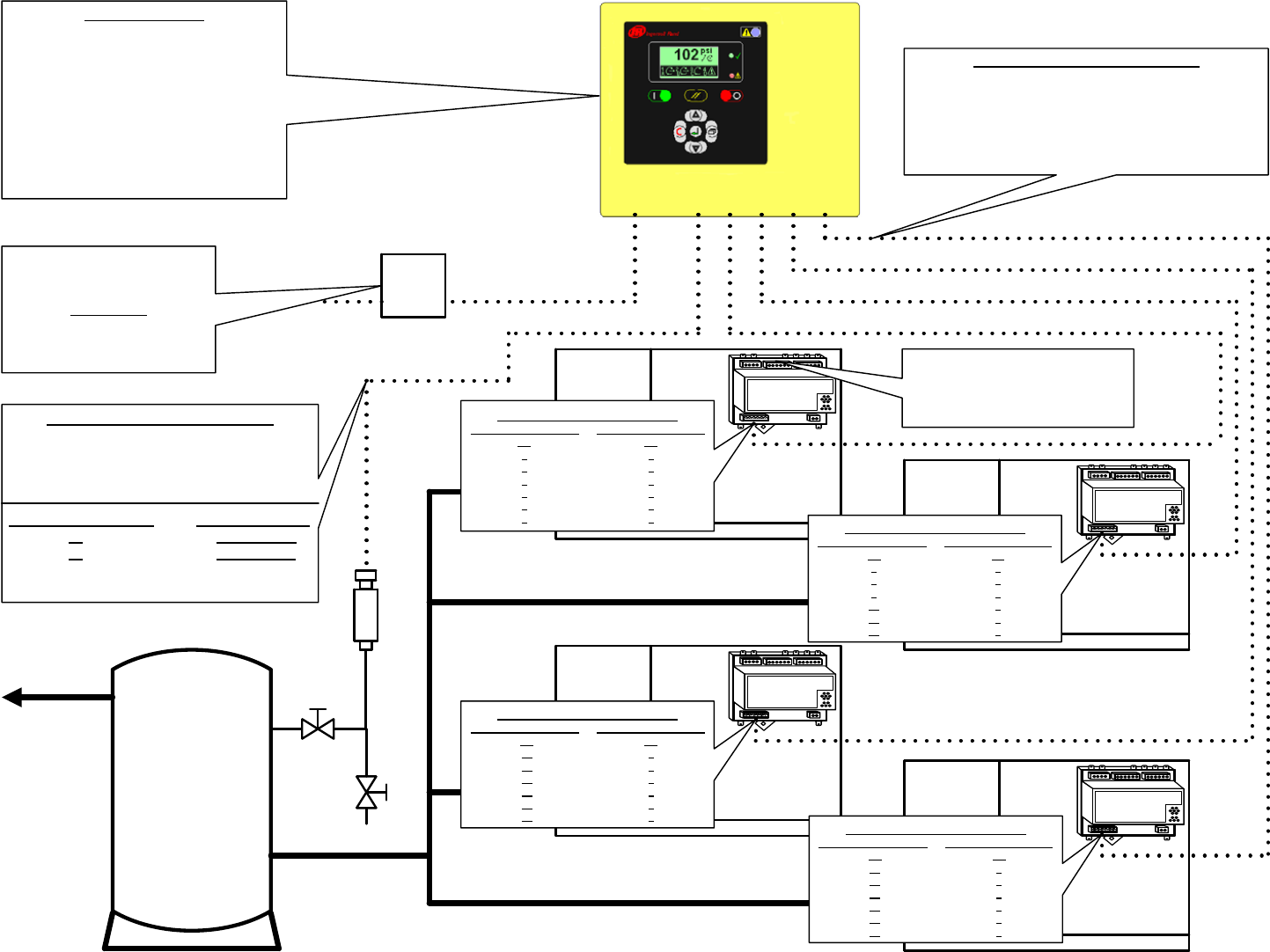
UNIT LOCATION
The X4I can be mounted on a wall using conventional
bolts. The X4I can be located remotely from the
compressors as long as it is within 330 feet (100 meters)
of cable length. The X4I must also be located within 330
feet (100 meters) of the system pressure transducer.
Compressor
#1 IR-PCB
DRIP LEG
PRESSURE TRANSDUCER
RECEIVER
Compressor
#3 IR-PCB
Compressor
#4 IR-PCB
Compressor
#2 IR-PCB
PRESSURE TRANSDUCER CABLE
2 Conductor Cable, 18 Gauge Stranded
Earth Shielded
No Greater Than 330FT (100M)
24VDC Control Voltage
X4I X05 CONNECTOR PT CONNECTOR
25 +VDC Pin #3
26 Signal Pin #1
Reference X4I Operations Manual for Pressure
Sensor Connection Details
COMPRESSOR CONTROL CABLE
7 Conductor Cable, 18 Gauge, Stranded, Earth Shielded
OR
Single Conductor Wire, 18 Gauge Stranded, Quantity (7)
In Grounded Conduit
No Greater Than 330FT (100M)
24VAC Control Voltage
Compressor #4 Control Cable
Compressor #3 Control Cable
Compressor #2 Control Cable
Compressor #1 Control Cable
Pressure Transducer Cable
Compressor #2 Control Cable
X4I X02 CONNECTOR IR-PCB CONNECTOR
V3 V1
71
82
93
10 4
11 5
12 6
Compressor #3 Control Cable
X4I X03 CONNECTOR IR-PCB CONNECTOR
V3 V1
13 1
14 2
15 3
16 4
17 5
18 6Compressor #4 Control Cable
X4I X04 CONNECTOR IR-PCB CONNECTOR
V4 V1
19 1
20 2
21 3
22 4
23 5
24 6
Compressor #1 Control Cable
X4I X01 CONNECTOR IR-PCB CONNECTOR
V1 V1
11
22
33
44
55
66
Reference X4I Compressor
Interconnect and Application Guide
For Connections Between The
Compressor And The IR-PCB
SPECIFICATIONS
Dimensions 11.45” x 9.45” x 6.0”
291mm x 241mm x 152mm
Weight 14lb (6.4kg)
Mounting Wall, 4 x screw fixings
Enclosure IP65, NEMA 4
Supply 230Vac +/- 10%, 50 Hz
115Vac +/- 10%, 60 Hz
Power 50VA
Temperature 32°F to 115°F
(0°C to 46°C)
Humidity 0% to 95% RH
(non-condensing)
Ingersoll Rand Automation
Model X4I
Supply Voltage Cable
Local Disconnect (Breaker) Box
Fused for 50VA
Power Cable
3 conductor (L, N, E)
(Sized in accordance with local
electrical and safety regulations).
On/Off
Switch
6
www.air.irco.com X4I System Automation
POWER SUPPLY
7
A fused switching isolator must be installed to the main
incoming power supply, external to the X4I. The isolator
must be fitted with a properly sized fuse to provide
adequate protection to the power supply cable used (in
accordance with local electrical and safety regulations).
1
VOLTAGE SELECT
23 4
X04
1
VOLTAGE SELECT
23 4
X04
230Vac
115Vac
EENL
LNE
X01
1234
XPM-TAC24
Power Supply Terminals
Ensure that the voltage select input is properly
jumpered for the incoming power. Default voltage
configuration is 230Vac.
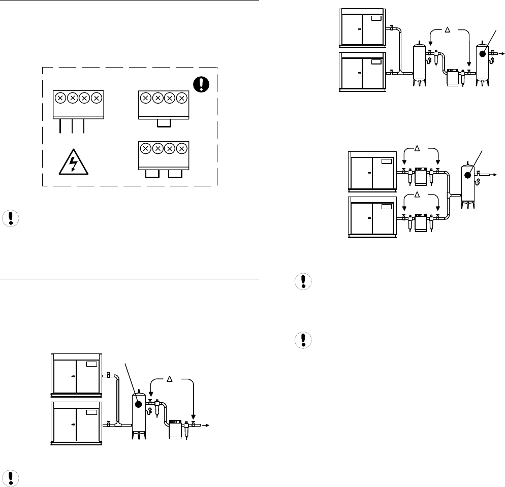
PRESSURE SENSOR LOCATION
The system pressure sensor (P) must be located where it
will see the air pressure that is common to all of the
compressors.
SUPPLY (WET) SIDE PRESSURE CONTROL
1
P
P
2
Pressure Sensor Located Before Cleanup Equipment
Dry side pressure will be lower than the system
pressure due to pressure differential losses across air
treatment equipment. The nominal system pressure will
reduce as the air treatment differential pressure
increases.
DEMAND (DRY) SIDE PRESSURE CONTROL
1P
2
P
Pressure Sensor Located After Shared Cleanup
Equipment
1
P
2
P
P
Pressure Sensor Located After Individual Cleanup
Equipment
Ensure each compressor is equipped with
independent excess pressure shutdown. An increase in
pressure differential across air treatment equipment can
result in excess compressor discharge pressure.
Regular routine monitoring of pressure differential
across air treatment equipment is recommended.
www.air.irco.com X4I System Automation
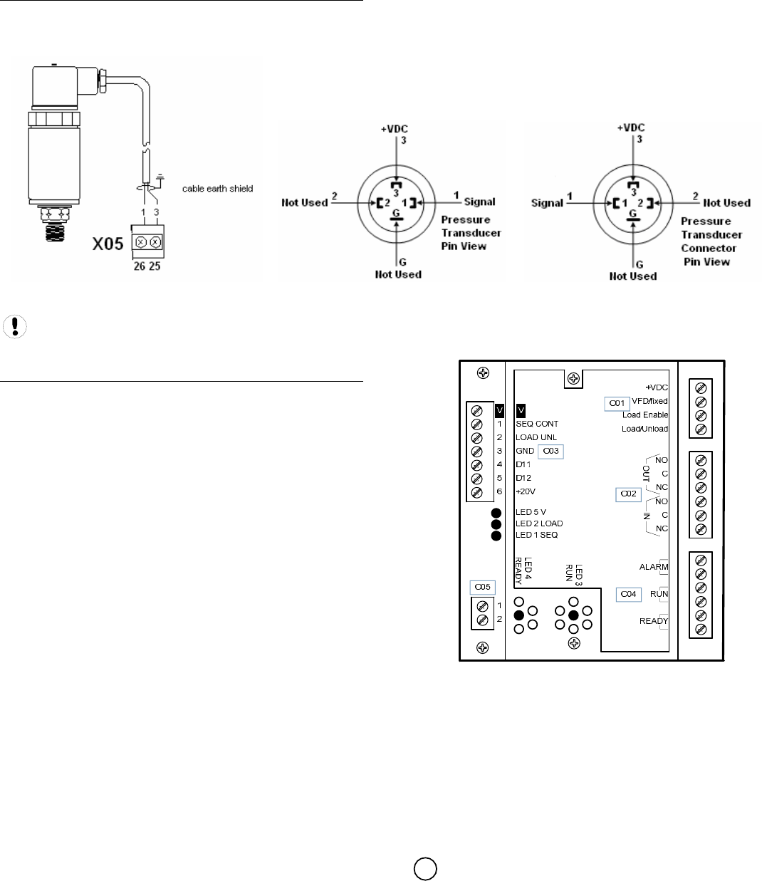
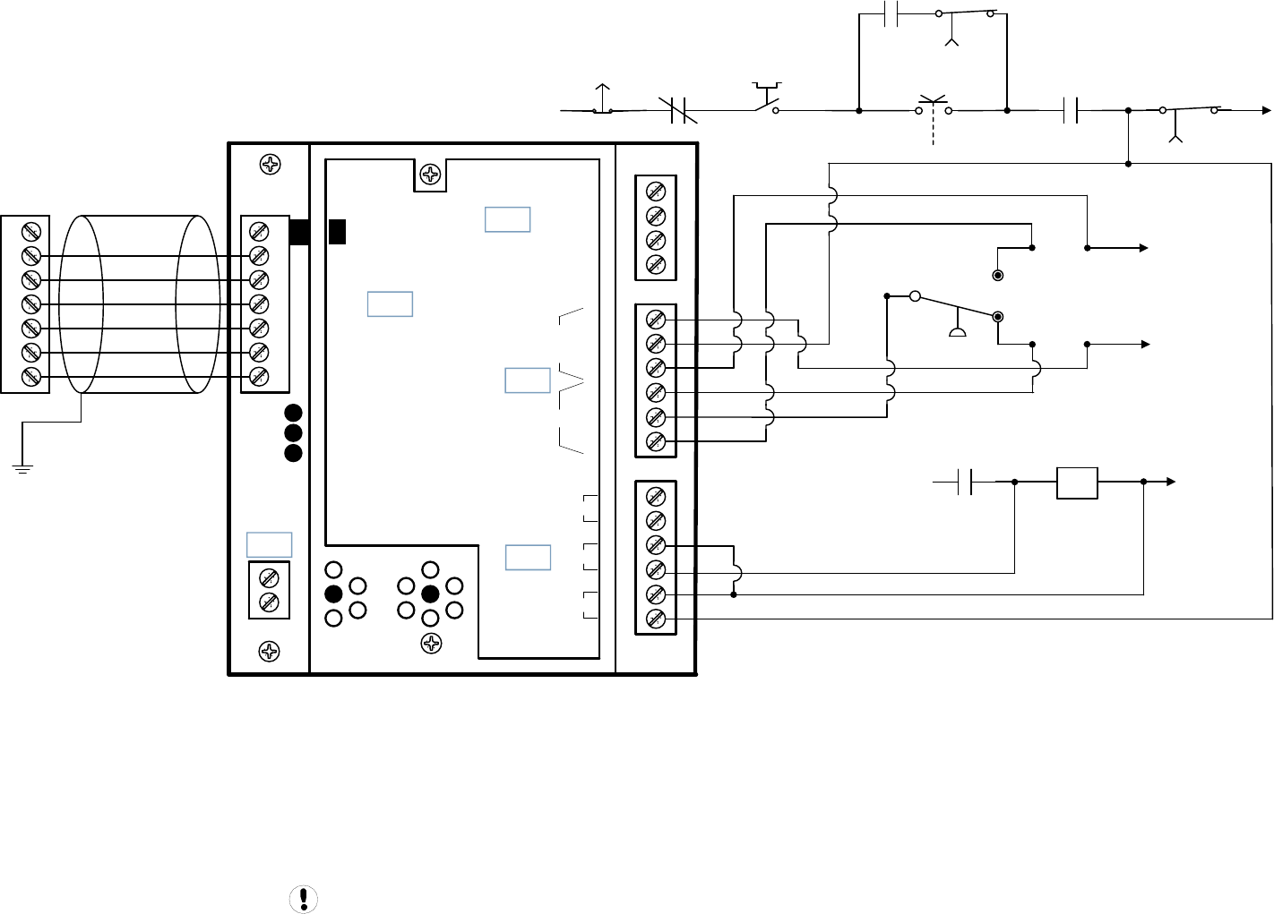
PRESSURE SENSOR CONNECTION
The pressure sensor connects to terminal X05 of the X4I
terminal PCB using a shielded 18 AWG maximum 2-
conductor cable no more than 330 feet (100 meters) in
length. The transducer threads are BPT. It is the
equivalent of ¼” NPT.
Pressure Sensor Wiring and Location
Wire polarity is important.
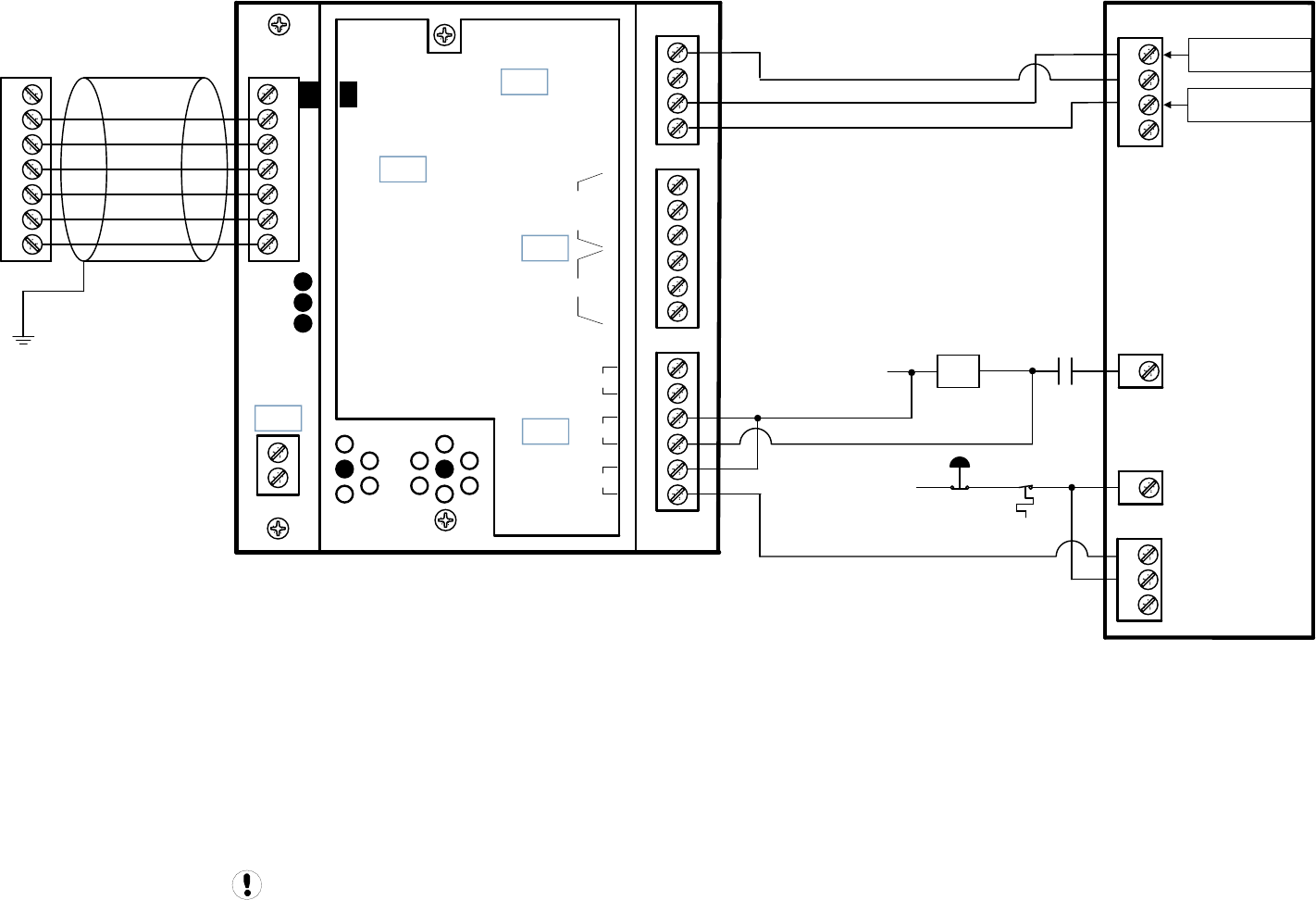
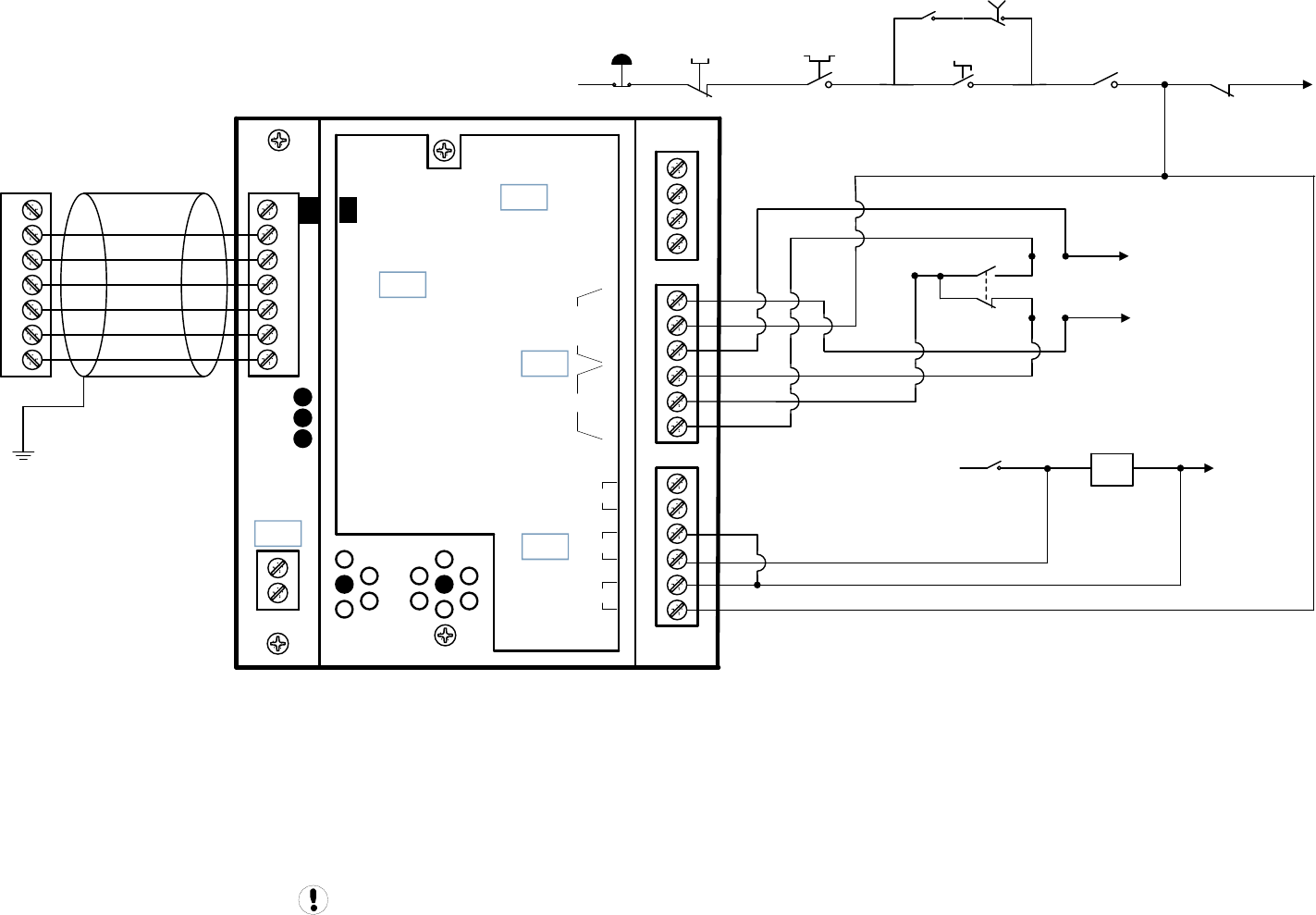
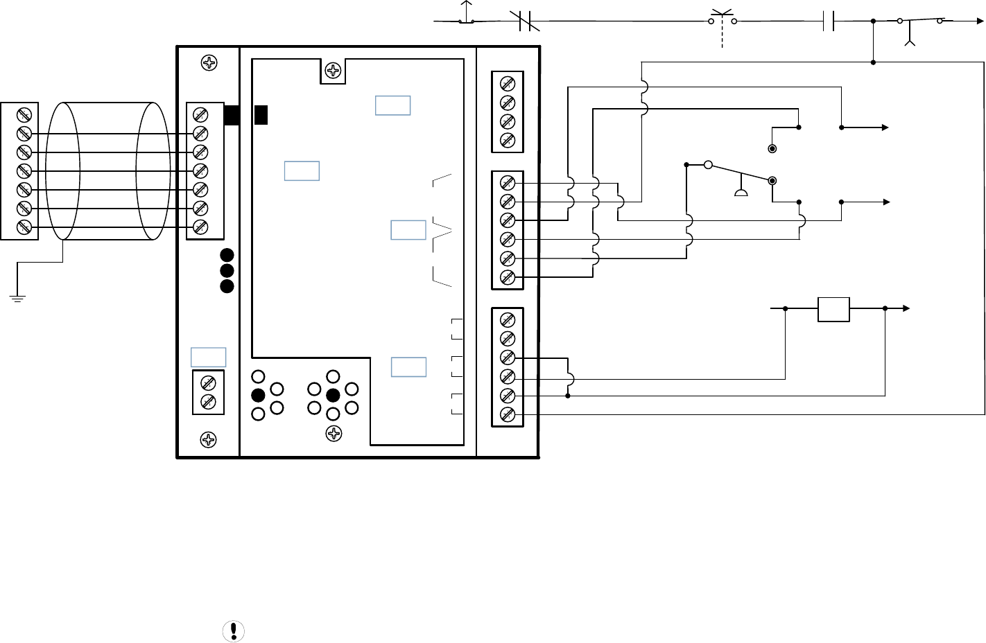
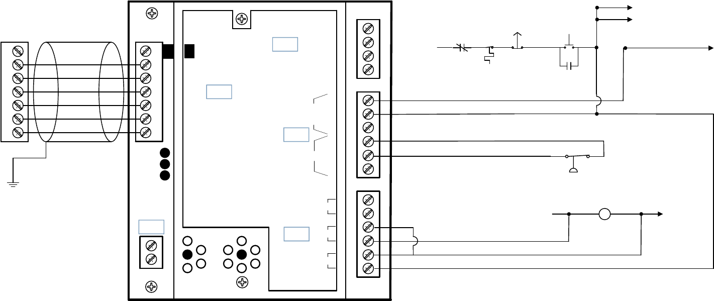
IR-PCB INTERFACE MODULE
8
The IR-PCB is designed to interface a compressor with
the X4I using a 7-conductor shielded cable or individual
wires run through grounded conduit no greater than 330
feet (100 meters) in length.
Each compressor in the system must be assigned a
unique identification number from 1 up to the number of
compressors in the system. The identification number
should be clearly indicated on each compressor for
operational reference.
For each compressor utilizing an IR-PCB, connection to
the X4I the signal wires must be made to the correct X4I
terminals for that compressor number. Compressor 1
should be wired to terminal X01 on the terminal PCB,
Compressor 2 should be wired to terminal X02 on the
terminal PCB, etc.
IR-PCB Interface Module
The IR-PCB is a DIN rail mountable module designed to
be installed within the compressor starter enclosure.
Each air compressor must be equipped with a
load/unload regulation system and, if not regulated with
a single electro-mechanical pressure switch, have a
facility for a remote load/unload control with the ability
to accept a volt-free switching contact input for remote
load/unload. Each air compressor must have Auto
Restart capability.
V For variable speed compressor(s) equipped with a
“variable/fixed” digital input function, install a 7-
conductor shielded cable from the IR-PCB to the X4I.
www.air.irco.com X4I System Automation
Consult the air compressor manual or your air
compressor supplier/specialist for details before
installing the X4I.
Each air compressor must be equipped with an
online/offline pressure regulation system capable of
accepting a remote load/unload signal through a volt
free switching contact or a single electro-mechanical
pressure switch.
The IR-PCB accepts a 12V to 250V input voltage detection
system and utilizes universal relay contact control
outputs (250V “CE” / 115V “UL” @ 5A maximum)
integrated directly into the circuits of an air compressor.
The IR-PCB avoids the need for additional relays or
remote inputs. The IR-PCB also acts as an electrical
barrier between the compressor and the X4I providing
protection and voltage isolation.
Consult the X4I Interconnect and Application Guide
prior to the installation of the X4I and the IR-PCB to the
air compressor.
INPUT FUNCTIONS
9
The IR-PCB is fitted with a six-pin terminal, C04, for
compressor monitoring. The IR-PCB uses two inputs,
Ready and Run, to determine compressor status. An
alarm input can be used if compressor warning
indication is available and required. The alarm input is
optional and is not necessary for system operation.
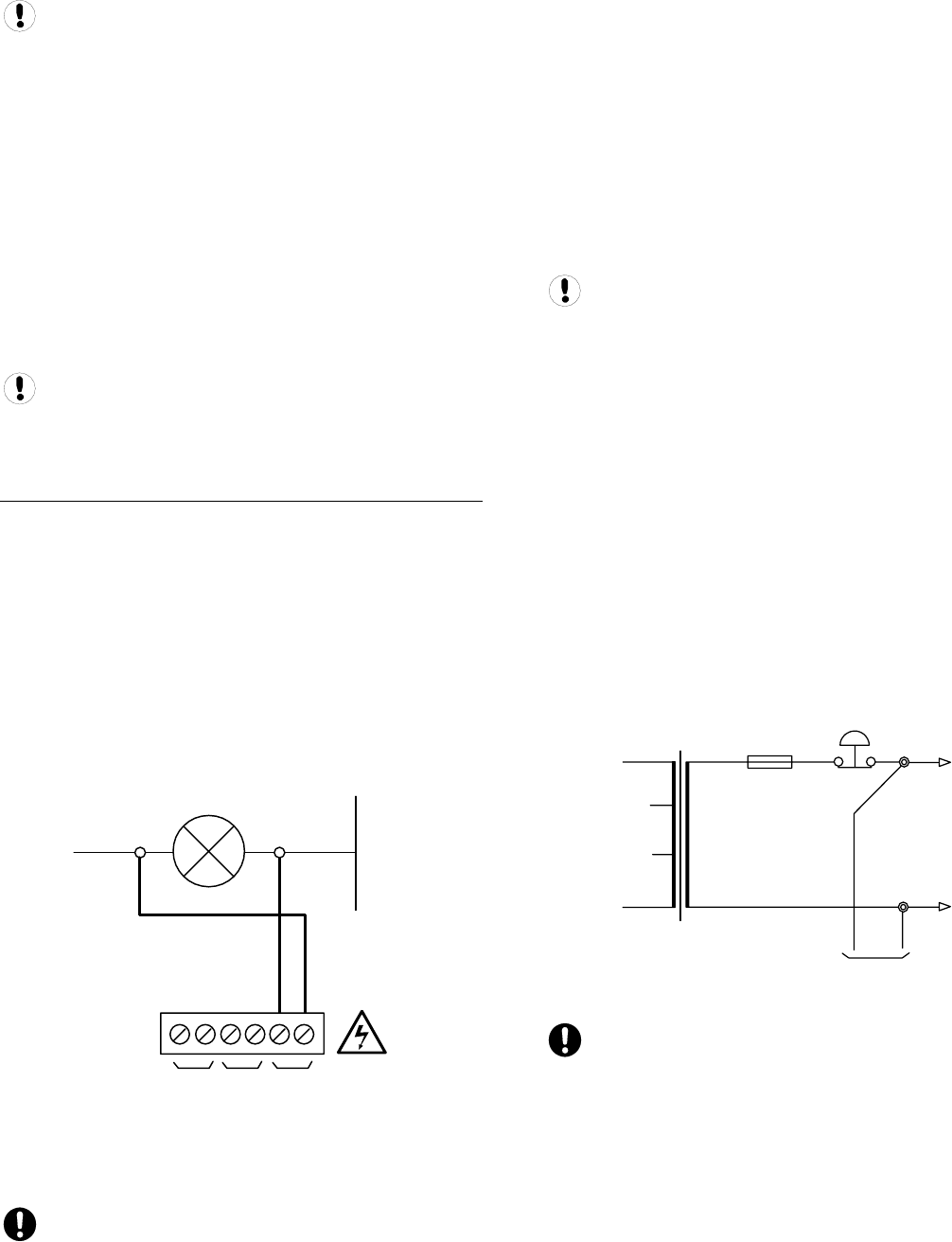
READY INPUT
The ‘Ready’ connection is intended to indicate that the
compressor is in a “started” state, has no alarm condition
that has shut down the compressor, and is ready to
respond to X4I regulation without manual intervention.
0V
+V
READY LAMP
RUN READY
ALARM
C04
Typical Ready Input Wiring
The READY input will accept 12V to 250V ac (50/60Hz)
or dc.
Do not connect a voltage greater than 250Vac/dc to
this input.
This input must be connected to a circuit of the
compressor control system that will be energized when
the compressor is in a started (standby or running)
condition. For example, locate the circuit across the
ready or operating lamp as shown.
The voltage to this input must de-energize when the
compressor is stopped and unavailable to produce air
upon a load signal, or the emergency stop button is
pressed, or when the compressor experiences a fault that
prevents the compressor from running.
When the compressor ready lamp or other control circuit
is energized, the IR-PCB will detect the voltage and signal
the X4I that the compressor is ready and available to
load and produce air when a load request signal is given.
The IR-PCB common input terminal must always be
connected to the neutral, common or 0V line of the
applied input voltage.
READY INPUT, ALTERNATIVE CONNECTION METHOD
In instances where a convenient voltage signal for a
compressor ready condition is not available, the “ready”
input can be connected directly to a constant compressor
control voltage (12V to 250Vac or dc). This will signal the
X4I that the compressor is ready and available at all
times when power is applied to the compressor. The X4I
has a built-in function to determine when a compressor
is not responding, or is in a shutdown condition, even if
the “ready” signal says otherwise. If the X4I requests a
compressor to run/load, but fails to detect a RUN signal
within 60 seconds, the X4I will regard the compressor as
“not ready” and indicate the compressor as not available.
If a RUN signal is reacquired at any time, the X4I will
automatically reset the compressor “not ready” condition
and re-establish control.
F1
+Vac
0Vac
READY
Alternative Ready Signal Connection
Never connect the “Ready” input positive voltage
connection directly to the output of a control system
transformer. Always connect after a fuse or circuit
breaker.
If a normally closed contact of an emergency stop button
is included in the compressor power supply circuit,
connect after the emergency stop button contacts. This
will instantly indicate a compressor “not ready” condition
if the emergency stop button is activated.
www.air.irco.com X4I System Automation
RUN INPUT
0V
RUN READY
ALARM
+V
MAIN (LINE) CONTACTOR
C04
Run Signal Circuit
The RUN input will accept 12V to 250V AC (50/60Hz)
only. DC cannot be used.
Do not connect a voltage greater than 250V to this
input.
12V to 250Vac must be applied to the “run” terminals
when the compressor motor is running.
This input can be connected to the control terminals A1
and A2 (coil) of the main starter contactor of the
compressor. When the compressor control system
energizes the main contactor, the IR-PCB will detect the
voltage across the contactor coil terminals and signal the
X4I that the compressor is running.
Alternatively, if the main contactor coil voltage is greater
than 250Vac, a contactor auxiliary switch can be used to
apply a suitable voltage to the “run” input terminals.
0V
+V
MAIN (LINE) CONTACTOR
0V
+V
AUXILIARY SWITCH
RUN READY
ALARM
C04
Run Signal Circuit with Auxiliary Switch
In instances where a motor starter contactor is not
available or accessible, any part of a compressor control
circuit that is energized when the compressor is running
can be monitored. For example: fan contactor or voltage
signal to a remote starter.
The IR-PCB input common terminal must always be
connected to the neutral, common or 0V line of the
applied input voltage.
WARNING INPUT (OPTIONAL)
The IR-PCB is equipped with a warning input that can be
used to detect warning conditions.
An alarm that stops the compressor, and/or
prevents the compressor from running is determined
from the “run” and “ready” inputs. Warning detection is
optional and is not a requirement.
Alarm Run Ready
Alarm Lamp 0V
+V
C04
Warning Input Circuit
The warning input will accept 12V to 250V AC (50/60Hz)
or DC.
Do not connect a voltage greater than 250Vac/DC to
this input.
This input can be connected to the terminals of an alarm
lamp or other accessible part of the control circuit that is
energized when the compressor is in a warning
condition.
If a warning condition is experienced the compressor
warning lamp, or warning circuit, will energize. The IR-
PCB will detect the voltage and signal the X4I that a
warning has occurred. If the compressor has no
accessible warning circuit, or this function is not
required, the IR-PCB alarm terminals can be ignored.
The IR-PCB input common terminal must always be
connected to the neutral, common or 0V line of the
applied input voltage.
10
www.air.irco.com X4I System Automation
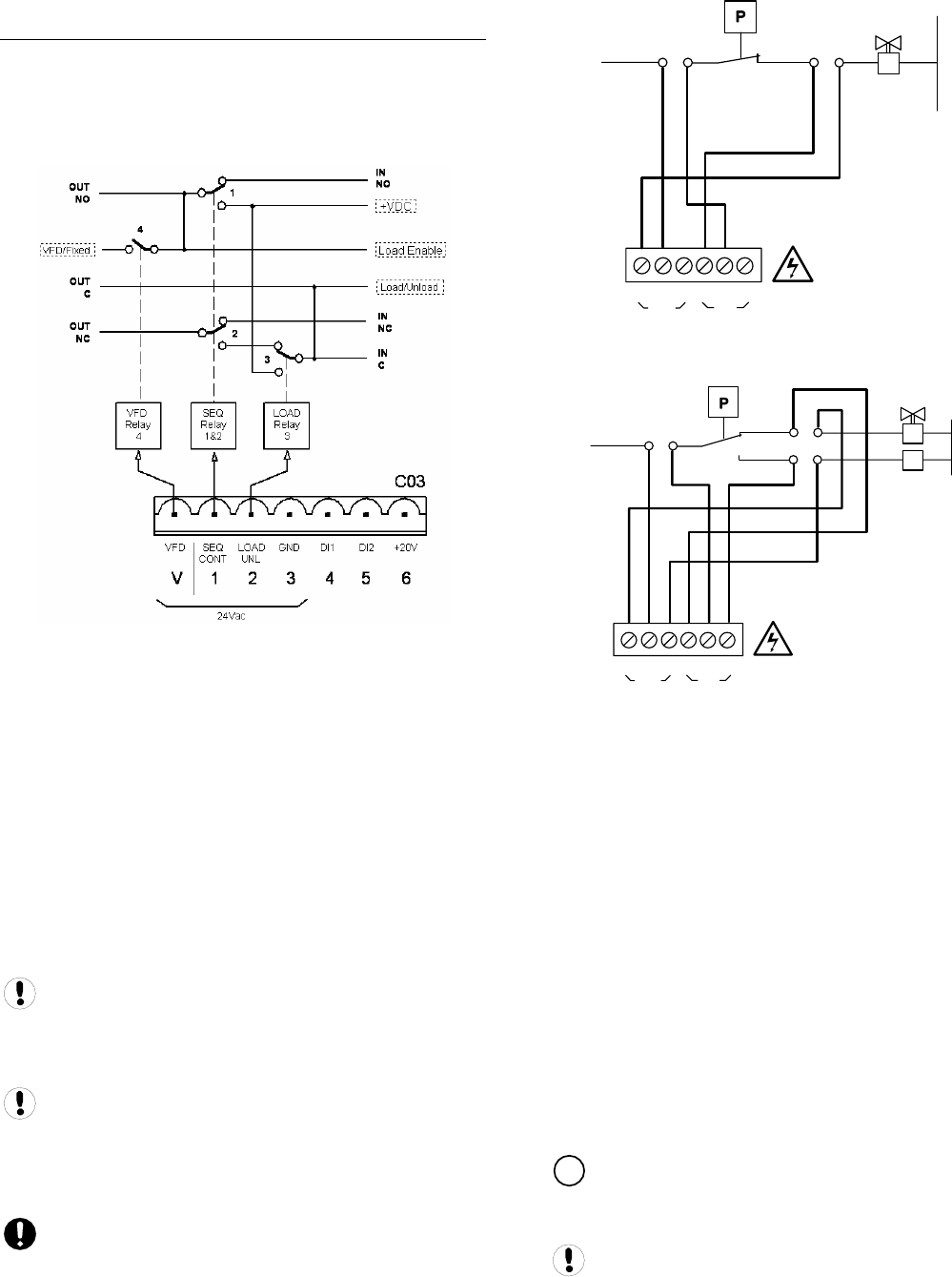
OUTPUT FUNCTIONS
11
The X4I will control the IR-PCB load/unload relay outputs
based on the active system load and unload pressure
setpoints. The IR-PCB load/unload relay contacts can be
used for compressor controllers that have electro-
mechanical pressure switch load/unload regulation.
IR-PCB Internal Output Circuits
The C01 and C02 terminals of the IR-PCB are intended to
control load and unload regulation of the compressor.
PRESSURE SWITCH REGULATION
For air compressors fitted with an electro-mechanical
pressure switch, a six-pin terminal C02 has been
provided to enable connection to a pressure switch that
has a two-wire or three-wire connection.
When connected, the pressure switch can be switched in
and out of circuit automatically. If the X4I is stopped or
experiences a failure or loss of power, pressure control
will automatically revert back to the pressure switch and
the compressor will continue to operate in “local” mode.
The local pressure settings of all compressors in the
system should be set in a cascaded manner such that the
system will operate normally in the event of X4I
inoperability.
The NC (normally closed) and NO (normally open)
terminal references of the IR-PCB are related to internal
connection functions and should not be referenced to the
connections of a compressor pressure switch, which will
generally be in reverse order.
Lethal voltages may be present on the terminals of
the air compressor pressure switch. Isolate the air
compressor power supply before starting any work.
+V
0V
LOAD
SOLENOID
C02
NO
OUT
C
NC
NO
C
NC
IN
Two Wire Pressure Switch Connections
+V 0V
LOAD
SOLENOID
RUN-ON
TIMER
C02
NO
OUT
C
NC
NO
C
NC
IN
Three Wire Pressure Switch Connections
DIGITAL REGULATION CONTROL TERMINAL C01
A 4-pin connector, C01, has been provided for air
compressor controllers fitted with digital inputs allowing
remote pressure regulation control.
This terminal provides volt free contact closure,
referenced to a common terminal pin, for:
• Remote Load Enable (remote/local
pressure regulation control)
• Remote Load (remote load/unload)
• Remote Variable Speed Regulation
Inhibit (remote variable/fixed speed
regulation control)
The “remote load enable” function provides the facility to
change the compressor load regulation from internal
control to a remote switching source (local/remote).
V The “remote variable/fixed” function provides for
multiple variable speed compressor regulation control on
variable speed compressor(s) equipped with this facility.
When using the “Variable/Fixed” function, the “V”
terminal of the IR-PCB must be connected to the
appropriate “V” terminal of the X4I (according to
www.air.irco.com X4I System Automation
compressor number) with an additional wire. Use a 7-
conductor shielded cable in this instance.
Compressors that use electronic pressure detection
but are not equipped with a remote pressure control
enable feature will not automatically revert to local
control if the X4I is stopped or experiences a fault or loss
of power.
Load/Unload
+VDC
Load Enable
VFD/Fixed
ir-PCB
Load/Unload
Load Enable
VFD/Fixed
+VDC
Load, Sequence, and VFD Connections
Compressor controller inputs common voltage may
be 0V or +V.
The local/remote pressure regulation input and/or
remote load input logic of some electronic pressure
sensor type controllers are reversed. In this instance, the
“pressure switch” outputs (terminal C02) can be used to
establish alternative logic control connections.
For Example:
If the compressor controller “Local/Remote Pressure
Control” input is a normally open type (local when open,
remote when closed), but the “Remote Load” input is a
normally closed type (load when open), the IR-PCB
pressure switch terminal contacts can be used to achieve
the correct switching logic.
C02
NO
OUT C
NC
NO
C
NC
IN
common
common
Local/Remote
Remote Load
Alternate Logic
Examine the “i-PCB” internal output circuit diagram to
establish any desired switching logic that may differ from
normal practice.
Do not attempt to utilize “Digital Pressure
Regulation Control” (terminal C01) and the “Pressure
Switch Control” (terminal C02) output connections at the
same time for different products. These two output
functions are internally connected and a short circuit
condition and/or malfunction may result.
The IR-PCB connection examples shown in this manual
are intended to provide a guide for the majority of
compressor control systems in use. Some compressors
have variations in operation and/or function; consult
your compressor supplier/specialist for advice.
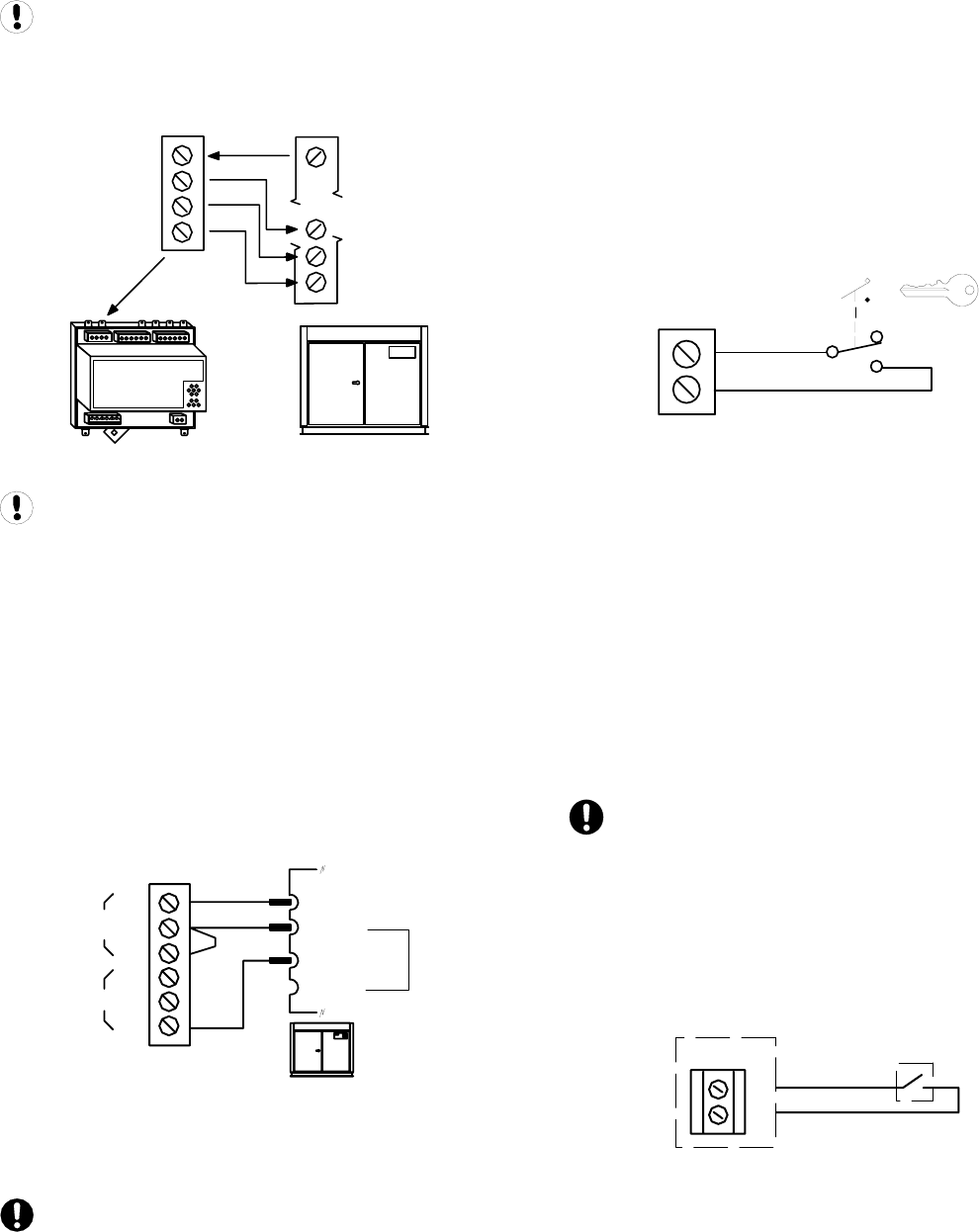
SERVICE MAINTENANCE SWITCH
The IR-PCB is equipped with a volt-free input (terminal
C05) that can be used to remove the compressor from
X4I control, without generating a fault condition, during
short-term maintenance or servicing periods.
1
2
C05
Service Maintenance Switch Circuit
When the “Service Maintenance Switch” input terminal
pins are connected together using a volt-free switching
contact, the X4I will indicate that the compressor is not
available but will not generate a warning, alarm, or
shutdown condition. The X4I will also remove the
compressor from the sequence strategy and substitute
with an alternative available compressor if necessary.
When the “Service Maintenance Switch” input circuit is
open again, the compressor will automatically be
accepted back in to the sequence strategy and will be
utilized when next required.
The use of a “key switch” is recommended for this
purpose in order to prevent the switch contacts being
inadvertently left in the closed circuit condition after
service maintenance is complete.
DO NOT connect any external voltage source to the
pins of terminal C05.
AUXILIARY INPUT (OPTION)
The X4I is equipped with an auxiliary input at terminals
31 and 32 (X07).
The function of the input is menu selectable and can be
adapted for differing application requirements.
31
X07
32
Auxiliary Input Circuit
The input is designed to detect a remote “volt-free”
switching contact (rated for a minimum 24VDC @ 10mA).
12
www.air.irco.com X4I System Automation
AUXILIARY OUTPUT (OPTION)
The X4I is equipped with a remote relay contact output at
terminals 33 and 34 (X08).
13
The function of the output is menu selectable and can be
adapted for differing application requirements.
X08
33
34
R6
Auxiliary Output Circuit
The remote output relay contacts are rated for 240V “CE”
/ 115V “UL” @ 5A maximum.
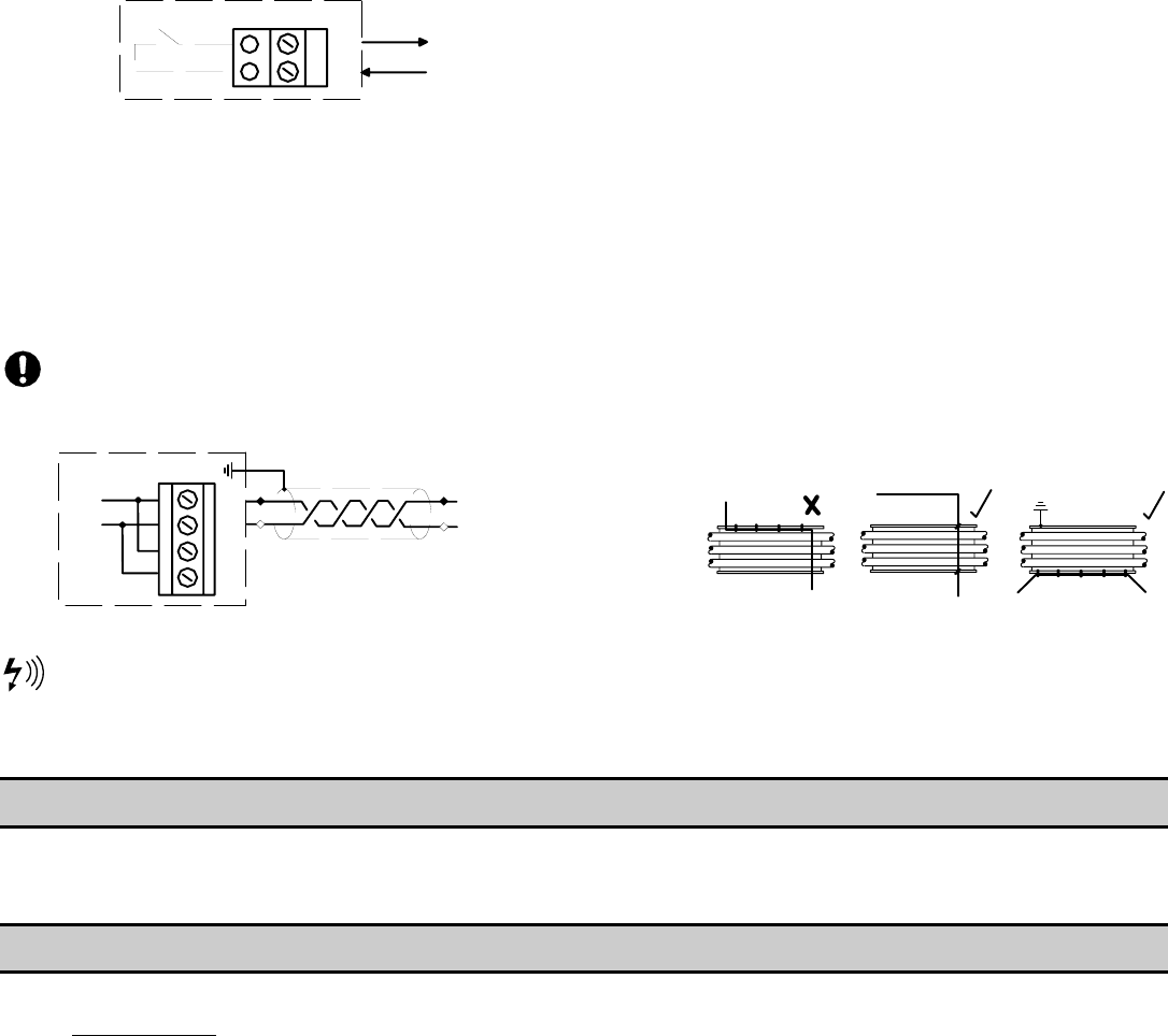
RS485 COMMUNICATIONS
The X4I is equipped with an RS485 network
communications capability using the proprietary
Multi485 protocol.
This can be only used for remote connectivity to
optional X4I expansion networked units and modules
with proprietary Multi485 communications capabilities.
28
30
27
29 L2
L1
RS485
L1
L2
X06
RS-485 Connection Circuit
RS485 data communications and other low voltage
signals can be subject to electrical interference. This
potential can result in intermittent malfunction or
anomaly that is difficult to diagnose. To avoid this
possibility, always use shielded cables, securely bonded
to a known ground at one end. In addition, give careful
consideration to cable routing during installation.
• Never route an RS485 data
communications or low voltage signal
cable alongside a high voltage or 3-
phase power supply cable. If it is
necessary to cross the path of a power
supply cable(s), always cross at a right
angle.
• If it is necessary to follow the route of
power supply cables for a short distance
(for example: from a compressor to a
wall along a suspended cable tray),
attach the RS485 or signal cable on the
outside of a grounded cable tray such
that the cable tray forms a grounded
electrical interference shield.
• Where possible, never route an RS485 or
signal cable near to equipment or
devices that may be a source of
electrical interference. For example: 3-
phase power supply transformer, high
voltage switchgear unit, frequency
inverter drive module, radio
communications antenna.
SECTION 5 — ASSISTANCE
Contacting Technical Support Services or Service Bulletins listed on the IR ServiceNet can provide further assistance if there
are other questions or concerns during Installation and Start-up. Also, additional Application and Compressor Interconnect
Guides will be posted and available on the IR ServiceNet as they are developed and created.
SECTION 6 — X4I OVERVIEW AND INTERCONNECT DRAWINGS
The following pages are to assist with the connection of the X4I to variety of Ingersoll Rand Compressors. These drawings
are for Guidance Only; connections may differ with date, model, type, variant, special, custom or concession builds. This
information is intended to be used in conjunction with the compressor’s original control circuit diagram.
www.air.irco.com X4I System Automation
Compressor
#1 IR-PCB
DRIP LEG
PRESSURE TRANSDUCER
RECEIVER
Compressor
#3 IR-PCB
Compressor
#4 IR-PCB
Compressor
#2 IR-PCB
PRESSURE TRANSDUCER CABLE
2 Conductor Cable, 18 Gauge Stranded
Earth Shielded
No Greater Than 330FT (100M)
24VDC Control Voltage
X4I X05 CONNECTOR PT CONNECTOR
25 +VDC Pin #3
26 Signal Pin #1
Reference X4I Operations Manual for Pressure
Sensor Connection Details
COMPRESSOR CONTROL CABLE
7 Conductor Cable, 18 Gauge, Stranded, Earth Shielded
OR
Single Conductor Wire, 18 Gauge Stranded, Quantity (7)
In Grounded Conduit
No Greater Than 330FT (100M)
24VAC Control Voltage
Compressor #4 Control Cable
Compressor #3 Control Cable
Compressor #2 Control Cable
Compressor #1 Control Cable
Pressure Transducer Cable
Compressor #2 Control Cable
X4I X02 CONNECTOR IR-PCB CONNECTOR
V3 V1
7 1
8 2
9 3
10 4
11 5
12 6
Compressor #3 Control Cable
X4I X03 CONNECTOR IR-PCB CONNECTOR
V3 V1
13 1
14 2
15 3
16 4
17 5
18 6 Compressor #4 Control Cable
X4I X04 CONNECTOR IR-PCB CONNECTOR
V4 V1
19 1
20 2
21 3
22 4
23 5
24 6
Compressor #1 Control Cable
X4I X01 CONNECTOR IR-PCB CONNECTOR
V1 V1
1 1
2 2
3 3
4 4
5 5
6 6
Reference X4I Compressor
Interconnect and Application Guide
For Connections Between The
Compressor And The IR-PCB
SPECIFICATIONS
Dimensions 11.45” x 9.45” x 6.0”
291mm x 241mm x 152mm
Weight 14lb (6.4kg)
Mounting Wall, 4 x screw fixings
Enclosure IP65, NEMA 4
Supply 230Vac +/- 10%, 50 Hz
115Vac +/- 10%, 60 Hz
Power 50VA
Temperature 32°F to 115°F
(0°C to 46°C)
Humidity 0% to 95% RH
(non-condensing)
Ingersoll Rand Automation
Model X4I
Supply Voltage Cable
Local Disconnect (Breaker) Box
Fused for 50VA
Power Cable
3 conductor (L, N, E)
(Sized in accordance with local
electrical and safety regulations).
On/Off
Switch
X4I Overview Page 14

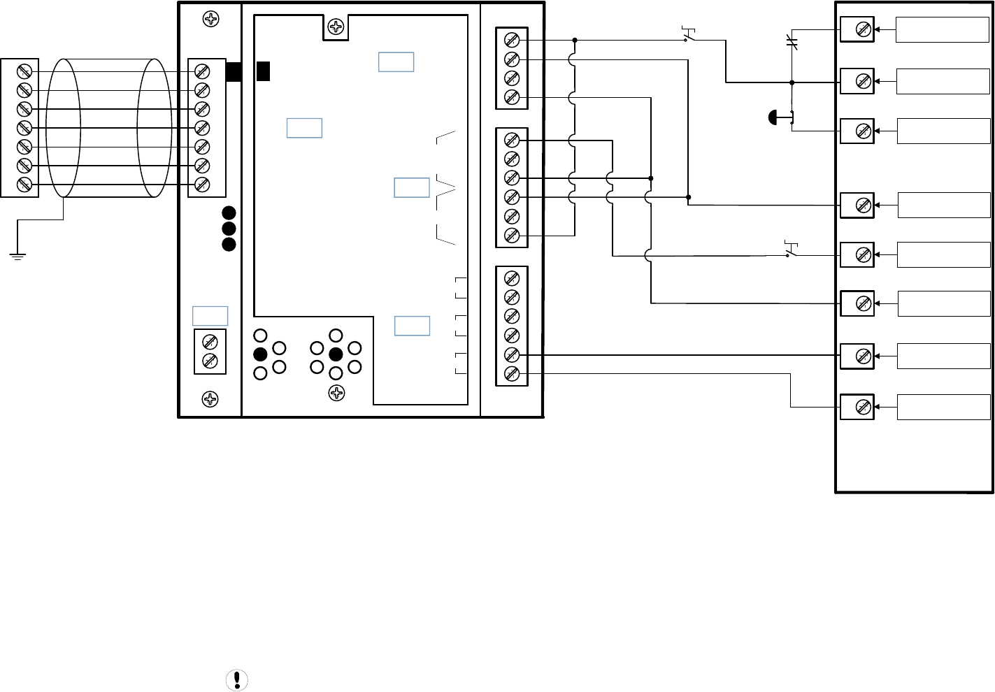
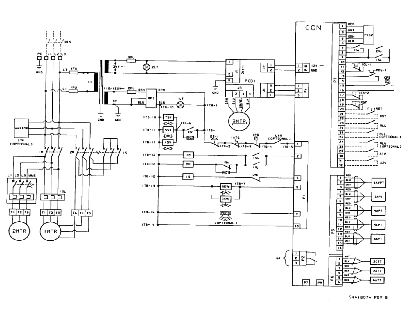
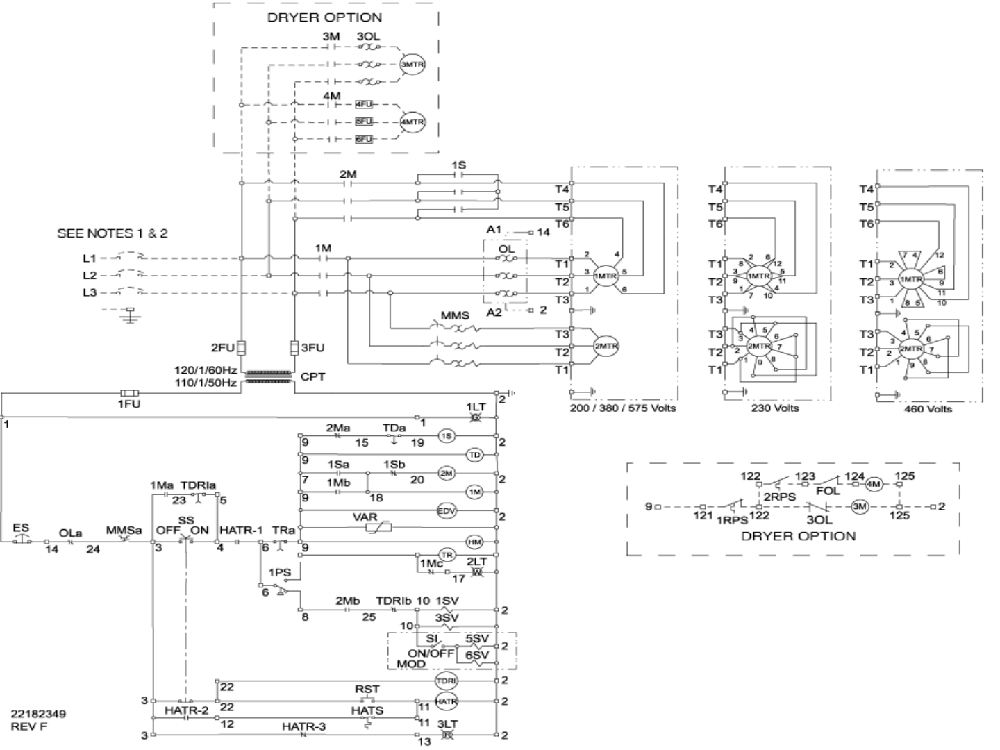
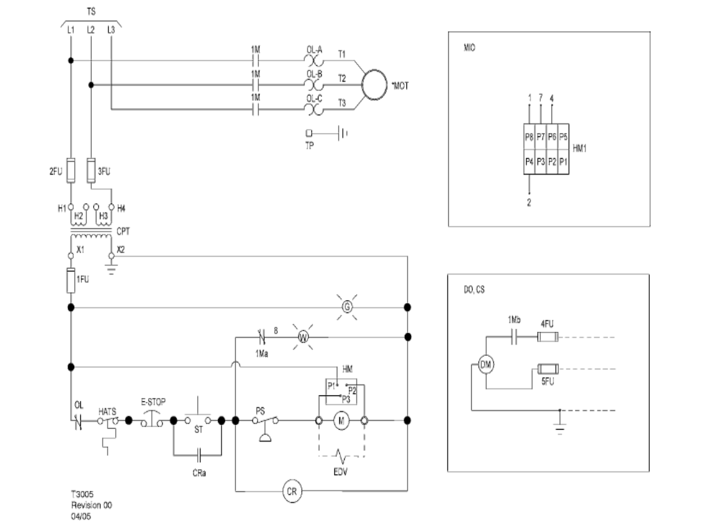
X4I Interconnect To Ingersoll Rand Unigy & Nirvana 20-40 HP Compressors
Refer to the X4I Overview Drawing for the X4I Compressor 2 through 4 X01 to IR-PCB terminal connections
For Unigy Compressors::
All Unigy Phase 1 compressors “MUST” be converted to Phase 2 or higher. Contact Technical Support Services for the CCN's required for this
conversion.
For Nirvana 20-40HP Compressors:
Remote Control “MUST” be set to on.
Check the Nirvana Software revision level. It “MUST” be updated to Version 1.10 or greater. Contact Technical Support Services to acquire the
update.
Drawing Notes For Unigy Phase 1 Machines:
Note: All Unigy Phase 1 compressors “MUST” be converted to Phase 2 or higher. Contact Technical Support Services for the CCN's required for this conversion. This Drawing on
Page 16 is a representation for “AFTER” the conversion is completed.
Note: The Unigy Target Pressure “MUST” be set equal to the “midpoint” of the X4I pressure control band.
Drawing Notes For Unigy Phase 2/3 Machines:
Note: The Unigy Target Pressure “MUST” be set equal to the “midpoint” of the X4I pressure control band.
Drawing Notes For Nirvana 20-40HP Machines:
Note: Remote Control “MUST” be set to on.
Note: The Nirvana Target Pressure “MUST” be set equal to the “midpoint” of the X4I pressure control band.
Guidance only; connections may differ with date, model, type, variant, special, custom or concession builds. This information is intended to
be used in conjunction with the compressor’s original control circuit diagram.
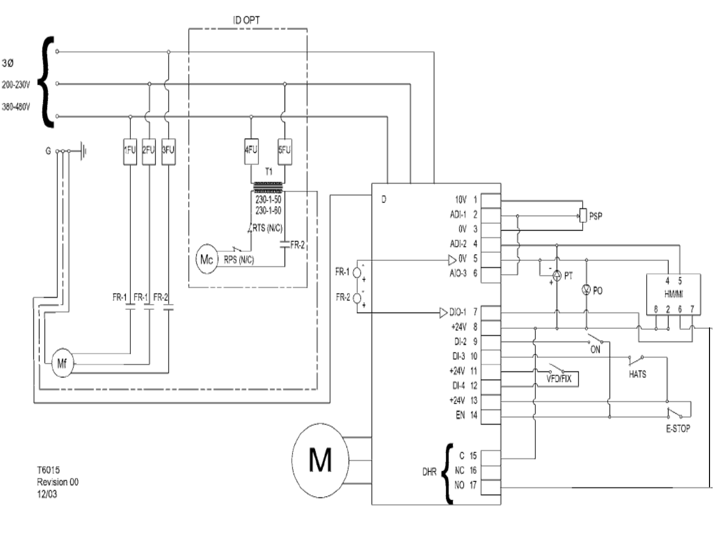
X4I Interconnect To Ingersoll Rand Unigy & Nirvana 20-40 HP Compressors Page 15
+24VDC
DI-4
EN
12
14
13
10 D13
17 NO
0V
5
+24VDC
11
SA1 HATS
E-STOP
DI-2
9
VFD/FIX
Guidance only; connections may differ with date, model, type, variant, special, custom or concession builds.
This information is intended to be used in conjunction with the compressor’s original control circuit diagram.
+VDC
Load Enable
Load/Unload
VFD/fixed
IN
NO
C
NC
NO
C
NC
RUN
ALARM
READY
OUT
V
SEQ CONT
LOAD UNL
GND
D11
D12
+20V
V
1
2
3
4
5
6
2
1
LED 5 V
LED 2 LOAD
LED 1 SEQ
LED 4
READY
LED 3
RUN
C03
C01
C02
C04
C05
IR-PCB
1
2
3
4
5
6
V1
Refer to the X4I Overview Drawing
for the X4I Compressor 2 through 4
terminal connections
X4I
COMPRESSOR #1
X01 TERMINAL
Unigy 1
7.5 - 15 HP
5.5 – 11 kW
Unigy Phase 1
Unigy Phase 1 1of2 Page 16
Unigy Phase 1
Unigy Phase 1 2of2 Page 17
Guidance only; connections may differ with date, model, type, variant, special, custom or concession builds.
This information is intended to be used in conjunction with the compressor’s original control circuit diagram.
SA1 HATS
E-STOP
VFD/FIX
+VDC
Load Enable
Load/Unload
VFD/fixed
IN
NO
C
NC
NO
C
NC
RUN
ALARM
READY
OUT
V
SEQ CONT
LOAD UNL
GND
D11
D12
+20V
V
1
2
3
4
5
6
2
1
LED 5 V
LED 2 LOAD
LED 1 SEQ
LED 4
READY
LED 3
RUN
C03
C01
C02
C04
C05
IR-PCB
1
2
3
4
5
6
V1
Refer to the X4I Overview Drawing
for the X4I Compressor 2 through 4
terminal connections
X4I
COMPRESSOR #1
X01 TERMINAL
+24VDC
DI-4
EN
12
14
13
10 D13
17 NO
0V
5
+24VDC
11
DI-2
9
Unigy
7.5 - 15 HP
5.5 – 11 kW
Unigy Phase 2/3
Unigy Phase 2/3 1of2 Page 18
Unigy Phase 2/3
Unigy Phase 2/3 2of2 Page 19
Remote
VFD / FIXED
Remote
LOAD / UNLOAD
Remote
LOAD ENABLE
33
32
18
12 +24VDC
6NC
COM
20
C
4
SAFE
37
Guidance only; connections may differ with date, model, type, variant, special, custom or concession builds.
This information is intended to be used in conjunction with the compressor’s original control circuit diagram.
+VDC
Load Enable
Load/Unload
VFD/fixed
IN
NO
C
NC
NO
C
NC
RUN
ALARM
READY
OUT
V
SEQ CONT
LOAD UNL
GND
D11
D12
+20V
V
1
2
3
4
5
6
2
1
LED 5 V
LED 2 LOAD
LED 1 SEQ
LED 4
READY
LED 3
RUN
C03
C01
C02
C04
C05
IR-PCB
1
2
3
4
5
6
V1
Refer to the X4I Overview Drawing
for the X4I Compressor 2 through 4
terminal connections
X4I
COMPRESSOR #1
X01 TERMINAL
Nirvana
20 - 40 HP
15 – 30 kW
Nirvana 15 – 30KW
(20 – 40HP)
Nirvana 15 - 30KW (20-40HP) 1of2 Page 20

Nirvana 15 - 30KW
(20-40HP)
Nirvana 15 - 30KW (20-40HP) 2of2 Page 21

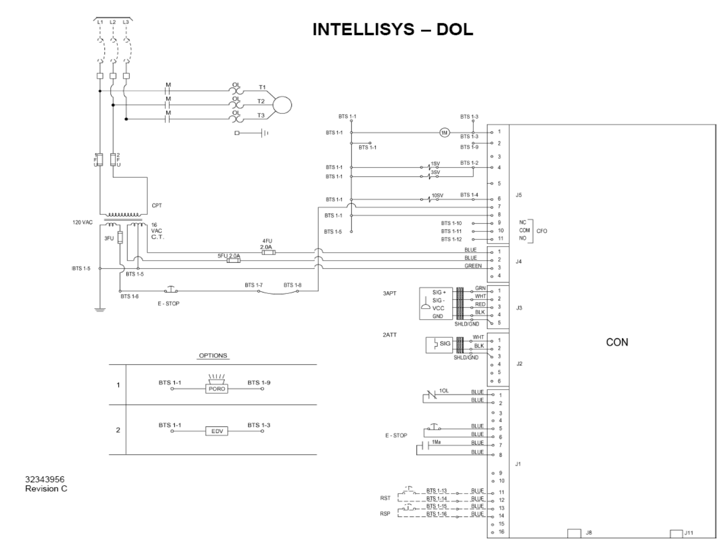
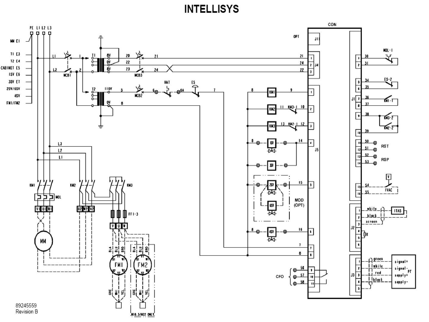
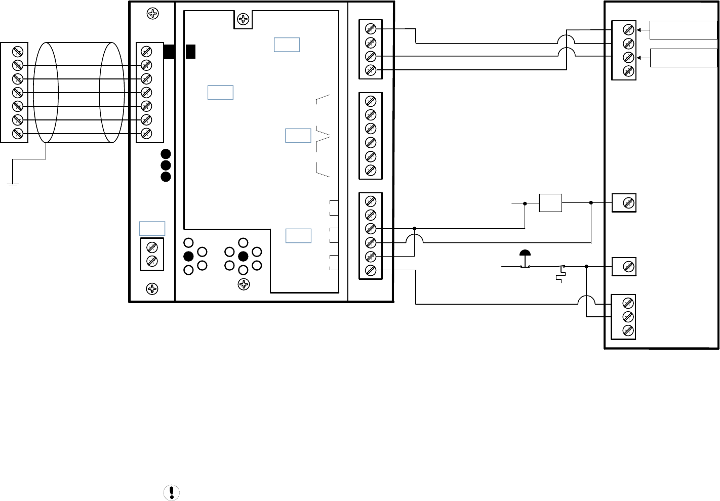
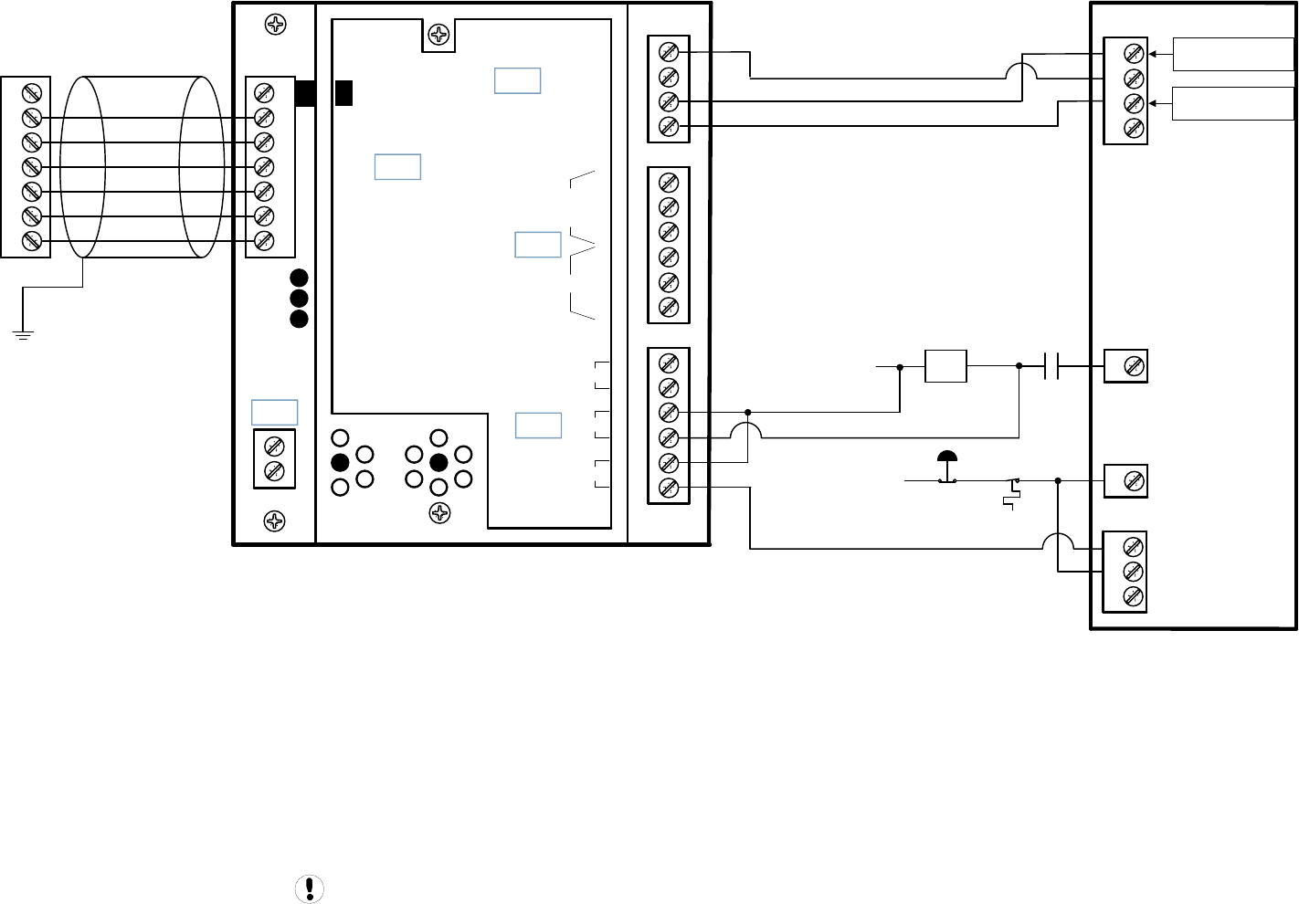
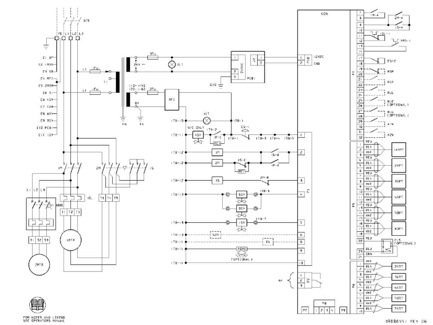
X4I Interconnect To Ingersoll Rand Intellisys Redeye Controlled Compressors
Refer to the X4I Overview Drawing for the X4I Compressor 2 through 4 X01 to IR-PCB terminal connections
For Redeye Intellisys Controlled Machines:
The ‘MASTER CONTROL’ setting of the Intellisys controller must be set to ‘ON’
The 'SEQUENCER' setting of the Intellisys controller must be set to 'ON'.
Auto Restart must be turned 'ON’ to allow the machines to stop in Auto restart when unloaded by the X4I.
The Intellisys must be run in the Online/Offline regulation mode. Do not use Modulation or ACS.
Check the Intellisys software revision level. Always update to the latest revision prior to operation.
For DSA Redeye Controllers, the 'SEQUENCER Option’ must be purchased. installed and then turned on.
CCN: 39225099
For ESA Redeye Intellisys Controllers, the SI1 interface (CCN: 42425710) must be used to allow the Redeye to be controlled by the X4I
For Sierra Redeye Intellisys Controllers, the SI1 interface (CCN: 42425710) must be used to allow the Redeye Controller to be sequenced/controlled
by the X4I
Drawing Notes For Redeye Intellisys Controlled Machines:
Note: For Star Delta starter wiring the X4I Run signal should be connected directly to the 1M coil.
Note: For Full voltage wiring the 1S (1Sb) interlock will not be used. The X4I Run signal can be connected directly to the Intellisys BTS1-28 terminal.
Guidance only; connections may differ with date, model, type, variant, special, custom or concession builds. This information is intended to be
used in conjunction with the compressor’s original control circuit diagram.
X4I Interconnect To Ingersoll Rand Intellisys Redeye Controlled Compressors Page 22
+VDC
Load Enable
Load/Unload
VFD/fixed
IN
NO
C
NC
NO
C
NC
RUN
ALARM
READY
OUT
V
SEQ CONT
LOAD UNL
GND
D11
D12
+20V
V
1
2
3
4
5
6
2
1
LED 5 VFD
LED 2 LOAD
LED 1 SEQ
LED 4
READY
LED 3
RUN
C03
C01
C02
C04
C05
IR-PCB
1
2
3
4
5
6
V1
X4I
COMPRESSOR #1
X01 TERMINAL
Refer to the X4I Overview Drawing
for the X4I Compressor 2 through 4
terminal connections
1
2
3
110VAC E-STOP
BTS2-
HATS BTS1-
34
18
16
12
11
Starter Interface Board
Analog Barrier Board
Guidance only; connections may differ with date, model, type, variant, special, custom or concession builds.
This information is intended to be used in conjunction with the compressor’s original control circuit diagram.
1M
0VAC 1
BTS1-
BTS3-
Remote Load/Unload
(was Remote Start)
Remote Load Enable
(was Remote Stop)
SSR Redeye
SSR Redeye 1of3 Page 23
SSR Redeye FV
SSR Redeye FV 2of3 Page 24
SSR Redeye SD
SSR Redeye SD 3of3 Page 25

X4I Interconnect To Ingersoll Rand Intellisys SE Controlled Compressors
Refer to the X4I Overview Drawing for the X4I Compressor 2 through 4 X01 to IR-PCB terminal connections
For All SE Intellisys Controlled Machines:
The 'SEQUENCER' setting of the Intellisys controller must be set to 'ON'.
Auto Restart must be turned 'ON’ to allow the machines to stop in Auto restart when unloaded by the X4I.
The Intellisys must be run in the Online/Offline regulation mode. Do not use Modulation or ACS.
Check the Intellisys software revision level. Always update to the latest revision prior to operation.
For UP SE Intellisys Controllers,
Minimum Software Version 1.11
CCN: 39217047 (w/o PORO)
CCN: 39217039 (w PORO)
When installing the Sequence Option to enable Remote Load/Unload, the Remote Start Stop input terminals are now used for the Remote Load
I nputs. Remote Start Stop will no longer be functional. The SI1 interface (CCN: 42425710) can be used in place of the Sequence Option to allow
the SE controlled machines to function with both Remote Load Unload and Remote Start Stop.
Software Version 1.20 and Greater
The 'CONTACT SEQUENCE' setting of the Intellisys controller must be set to 'ON'.
Drawing Notes For UP SE Intellisys Controlled Machines:
Note: For Star Delta starter wiring the X4I Run signal should be connected directly to the 1M coil.
Note: For Full voltage wiring the 1S (1Sb) interlock will not be used. The X4I Run signal can be connected directly to the Intellisys J5-1 terminal.
Note: For Pegasus machines wiring may be factory installed connecting the Intellisys Alarm Relay J5-9, J5-10 and J5-11 to a terminal strip but unused. Remove any factory installed
wiring from the Intellisys Alarm Relay contacts and connect the X4I Interface board wiring directly to the Intellisys Alarm Relay terminals J5-9 and J5-10.
For ESA SE Intellisys Controllers, the 'SEQUENCER Option’ must be purchased. installed and then turned on.
Minimum Software Version 1.40
CCN: 39217047 (w/o PORO)
CCN: 39217039 (w PORO)
When installing the Sequence Option to enable Remote Load/Unload, the Remote Start Stop input terminals are now used for the Remote Load
I nputs. Remote Start Stop will no longer be functional. The SI1 interface (CCN: 42425710) can be used in place of the Sequence Option to allow
the SE controlled machines to function with both Remote Load Unload and Remote Start Stop.
Drawing Notes For ESA SE Intellisys Controlled Machines:
Note: For Star Delta starter wiring the X4I Run signal should be connected directly to the 1M coil.
Note: For Full voltage wiring the 1S (1Sb) interlock will not be used. The X4I Run signal can be connected directly to the Intellisys J5-1 terminal.
For DSA SE Intellisys Controllers, the 'SEQUENCER Option’ must be purchased. installed and then turned on.
CCN: 22179238
When installing the Sequence Option to enable Remote Load/Unload, the Remote Start Stop input terminals are now used for the Remote Load
inputs. Remote Start Stop will no longer be functional. The SI1 interface (CCN: 42425710) can be used in place of the Sequence Option to allow
the SE controlled machines to function with both Remote Load Unload and Remote Start Stop.
Drawing Notes For DSA SE Intellisys Controlled Machines:
Note: For Star Delta starter wiring the X4I Run signal should be connected directly to the 1M coil.
Note: For Full Voltage wiring, the 1S (1Sb) interlock will not be used. The X4I Run signal can be connected directly to the Intellisys terminal 42.
For Sierra SE Intellisys Controllers, the SI1 interface (CCN: 42425710) must be used to allow the SE Controller to be sequenced/controlled by the X4I
Guidance only; connections may differ with date, model, type, variant, special, custom or concession builds. This information is intended to be
used in conjunction with the compressor’s original control circuit diagram.
X4I Interconnect To Ingersoll Rand Intellisys SE Controlled Compressors Page 26

E-STOP
110VAC
1M
0VAC
Guidance only; connections may differ with date, model, type, variant, special, custom or concession builds.
This information is intended to be used in conjunction with the compressor’s original control circuit diagram.
+VDC
Load Enable
Load/Unload
VFD/fixed
IN
NO
C
NC
NO
C
NC
RUN
ALARM
READY
OUT
V
SEQ CONT
LOAD UNL
GND
D11
D12
+20V
V
1
2
3
4
5
6
2
1
LED 5 VFD
LED 2 LOAD
LED 1 SEQ
LED 4
READY
LED 3
RUN
C03
C01
C02
C04
C05
IR-PCB
1
2
3
4
5
6
V1
X4I
COMPRESSOR #1
X01 TERMINAL
Refer to the X4I Overview Drawing
for the X4I Compressor 2 through 4
terminal connections
Remote Load/Unload
(was Remote Start)
Remote Load/Unload
(was Remote Start)
1
9
10
11
J5
7
11
12
13
14
J5
J5
J1
Intellisys SE
UP Series
SE UP
SE UP 1of2 Page 27
SE UP
SE UP 2of2 Page 28
Remote Load/Unload
(was Remote Start)
Remote Load/Unload
(was Remote Start)
1
9
10
11
E-STOP
J5
7
11
12
13
14
J5
J5
J1
110VAC
1M
0VAC
Guidance only; connections may differ with date, model, type, variant, special, custom or concession builds.
This information is intended to be used in conjunction with the compressor’s original control circuit diagram.
HAT
MCB2
+VDC
Load Enable
Load/Unload
VFD/fixed
IN
NO
C
NC
NO
C
NC
RUN
ALARM
READY
OUT
V
SEQ CONT
LOAD UNL
GND
D11
D12
+20V
V
1
2
3
4
5
6
2
1
LED 5 VFD
LED 2 LOAD
LED 1 SEQ
LED 4
READY
LED 3
RUN
C03
C01
C02
C04
C05
IR-PCB
1
2
3
4
5
6
V1
X4I
COMPRESSOR #1
X01 TERMINAL
Refer to the X4I Overview Drawing
for the X4I Compressor 2 through 4
terminal connections
Intellisys SE
ESA Series
SE ESA
SE ESA 1of2 Page 29
SE ESA
SE ESA 2of2 Page 30
1M
0VAC
Remote Load/Unload
(was Remote Start)
Remote Load/Unload
(was Remote Start)
34
33
32
110VAC E-STOP
J5
36
6
5
4
3
J5
J5
J1
42
Guidance only; connections may differ with date, model, type, variant, special, custom or concession builds.
This information is intended to be used in conjunction with the compressor’s original control circuit diagram.
1ATS
+VDC
Load Enable
Load/Unload
VFD/fixed
IN
NO
C
NC
NO
C
NC
RUN
ALARM
READY
OUT
V
SEQ CONT
LOAD UNL
GND
D11
D12
+20V
V
1
2
3
4
5
6
2
1
LED 5 VFD
LED 2 LOAD
LED 1 SEQ
LED 4
READY
LED 3
RUN
C03
C01
C02
C04
C05
IR-PCB
1
2
3
4
5
6
V1
X4I
COMPRESSOR #1
X01 TERMINAL
Refer to the X4I Overview Drawing
for the X4I Compressor 2 through 4
terminal connections
Intellisys SE
DSA Contact
Cooled
SE DSA
SE DSA 1of2 Page 31
SE DSA
SE DSA 2of2 Page 32

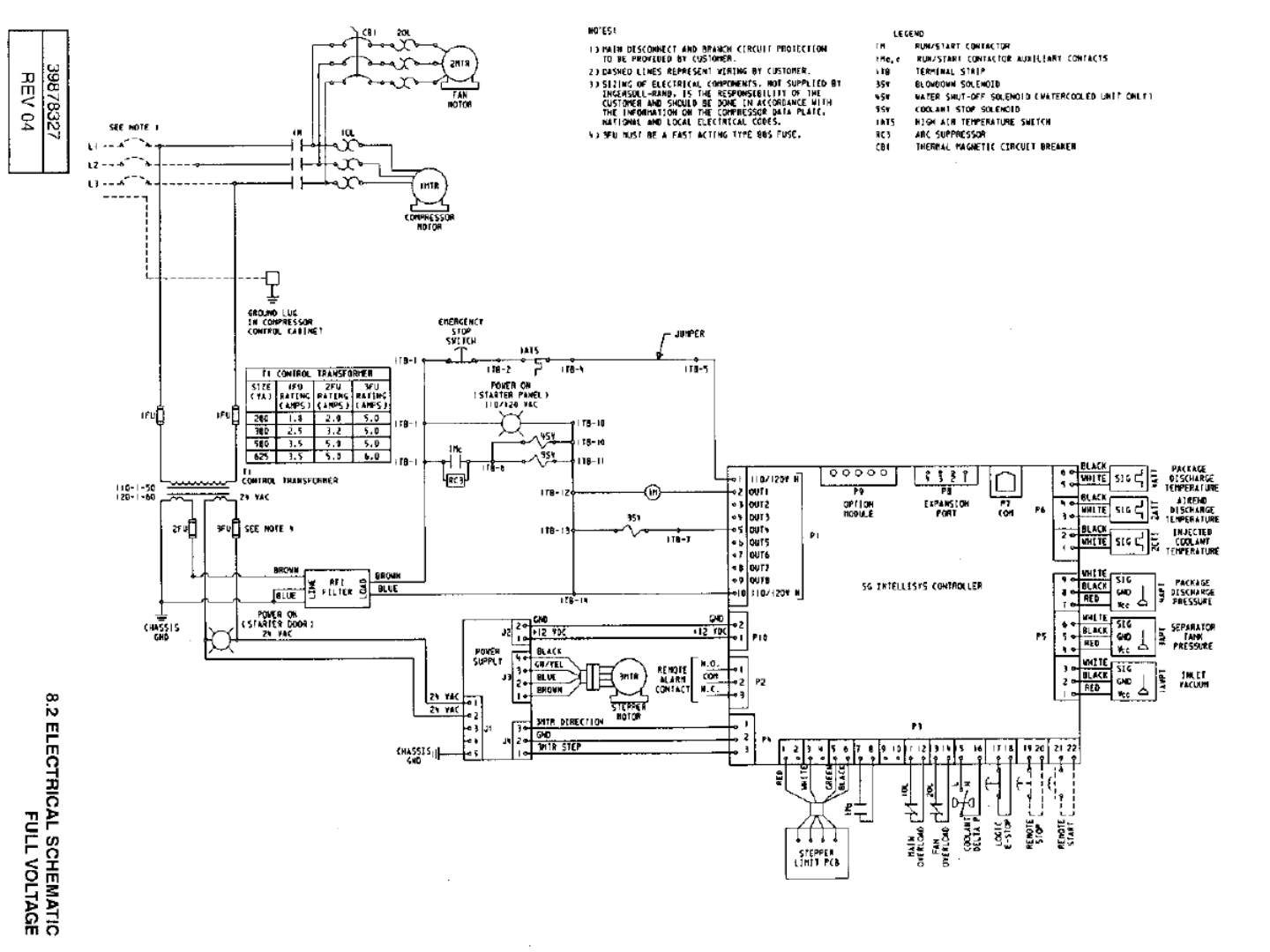
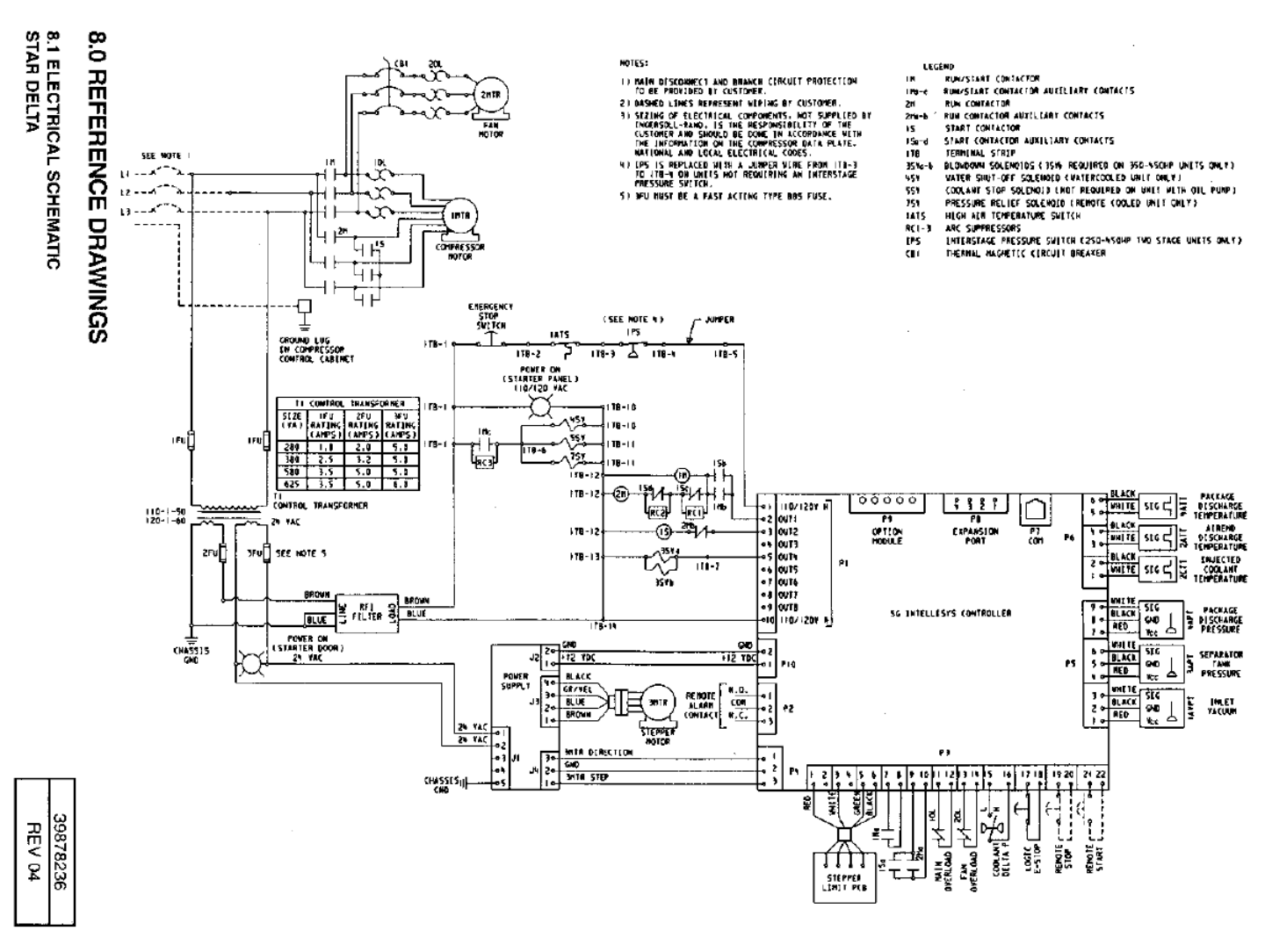
X4I Interconnect To Ingersoll Rand Intellisys SG Controlled Compressors
Refer to the X4I Overview Drawing for the X4I Compressor 2 through 4 X01 to IR-PCB terminal connections
For SG Intellisys Controlled Machines:
The 'SEQUENCER' setting of the Intellisys controller must be set to 'ON'.
Auto Restart must be turned 'ON’ to allow the machines to stop in Auto restart when unloaded by the X4I.
The Intellisys must be run in the Online/Offline regulation mode. Do not use Modulation or ACS.
Check the Intellisys software revision level. Always update to the latest revision prior to operation.
For Sierra SG Intellisys Controllers, the SI1 interface (CCN: 42425710) can be used as an alternative to allow the SG Controller to be sequenced/
controlled by the X4I
Drawing Notes For SG Intellisys Controlled Machines:
Note: For Star Delta starter wiring the X4I Run signal should be connected directly to the 1M coil.
Note: For Full Voltage wiring, the 1S (1Sb) interlock will not be used. The X4I Run signal can be connected directly to the Intellisys P1-2 terminal.
Refer to the X4I Overview Drawing for the X4I Compressor 2 through 4 X01 to IR-PCB terminal connections
Guidance only; connections may differ with date, model, type, variant, special, custom or concession builds. This information is intended to be
used in conjunction with the compressor’s original control circuit diagram.
X4I Interconnect To Ingersoll Rand Intellisys SG Controlled Compressors Page 33
1M
0VAC
Remote Load/Unload
Remote Load Enable
3
2
1
110VAC E-STOP
P1
1
25
26
27
28
P2
P1
P3
2
Guidance only; connections may differ with date, model, type, variant, special, custom or concession builds.
This information is intended to be used in conjunction with the compressor’s original control circuit diagram.
1ATS
+VDC
Load Enable
Load/Unload
VFD/fixed
IN
NO
C
NC
NO
C
NC
RUN
ALARM
READY
OUT
V
SEQ CONT
LOAD UNL
GND
D11
D12
+20V
V
1
2
3
4
5
6
2
1
LED 5 VFD
LED 2 LOAD
LED 1 SEQ
LED 4
READY
LED 3
RUN
C03
C01
C02
C04
C05
IR-PCB
1
2
3
4
5
6
V1
X4I
COMPRESSOR #1
X01 TERMINAL
Refer to the X4I Overview Drawing
for the X4I Compressor 2 through 4
terminal connections
Intellisys SG
1Sb
SG SSR
SG SSR 1of2 Page 34
SG SSR
SG SSR 2of2 Page 35
Guidance only; connections may differ with date, model, type, variant, special, custom or concession builds.
This information is intended to be used in conjunction with the compressor’s original control circuit diagram.
1M
0VAC
Remote Load/Unload
Remote Load Enable
3
2
1
110VAC E-STOP
P1
1
25
26
27
28
P2
P1
P3
2
1ATS
+VDC
Load Enable
Load/Unload
VFD/fixed
IN
NO
C
NC
NO
C
NC
RUN
ALARM
READY
OUT
V
SEQ CONT
LOAD UNL
GND
D11
D12
+20V
V
1
2
3
4
5
6
2
1
LED 5 VFD
LED 2 LOAD
LED 1 SEQ
LED 4
READY
LED 3
RUN
C03
C01
C02
C04
C05
IR-PCB
1
2
3
4
5
6
V1
X4I
COMPRESSOR #1
X01 TERMINAL
Refer to the X4I Overview Drawing
for the X4I Compressor 2 through 4
terminal connections
Intellisys SG
1Sb
SG Sierra
SG Sierra 1of2 Page 36
SG Sierra
SG Sierra 2of2 Page 37

X4I Interconnect To Ingersoll Rand Pressure Switch Controlled Compressors
Refer to the X4I Overview Drawing for the X4I Compressor 2 through 4 X01 to IR-PCB terminal connections
For All Compressors:
Compressors to be connected must have automatic Start / Stop capability .
Drawing Notes For Pressure Switch Controller Machines:
Ensure each compressor is equipped with independent Excessive Pressure Shutdown Switch. An increase in pressure differential across air
treatment equipment can result in excess compressor discharge pressure. See Pages 84 and 85 for an example drawing. In most applications,
the model and type of pressure switch supplied with the compressor can be used as the Excessive Pressure Shutdown Switch. If this is specific
model/type of pressure switch is not readily available, any pressure switch can be utilized as long as it equals or exceeds the specifications of
the pressure switch found on the compressor.
Set the Excessive Pressure Shutdown Switch to “OPEN” 5 PSI less than the maximum discharge pressure recommended by the compressor
manufacturer.
Guidance only; connections may differ with date, model, type, variant, special, custom or concession builds. This information is intended to
be used in conjunction with the compressor’s original control circuit diagram.
X4I Interconnect To Ingersoll Rand Pressure Switch Controlled Compressors Page 38
KM1 0 VAC
KM1 Relay
Contact
PTo TM2 Relay
To KM1 Contact
To KM2 Contact
Guidance only; connections may differ with date, model, type, variant, special, custom or concession builds.
This information is intended to be used in conjunction with the compressor’s original control circuit diagram.
+VDC
Load Enable
Load/Unload
VFD/fixed
IN
NO
C
NC
NO
C
NC
RUN
ALARM
READY
OUT
V
SEQ CONT
LOAD UNL
GND
D11
D12
+20V
V
1
2
3
4
5
6
2
1
LED 5 VFD
LED 2 LOAD
LED 1 SEQ
LED 4
READY
LED 3
RUN
C03
C01
C02
C04
C05
IR-PCB
1
2
3
4
5
6
V1
X4I
COMPRESSOR #1
X01 TERMINAL
Refer to the X4I Overview Drawing
for the X4I Compressor 2 through 4
terminal connections
E-STOP
110VAC
HATR
Contact
Restart TD
Relay
Contact
SS
MOL
Contact
SSR UP5 11-22 SD
SSR UP5 11-22 SD 1of2 Page 39
SSR UP5 11-22 SD
SSR UP5 11-22 SD 2of2 Page 40
KM1 0 VAC
KM1 Relay
Contact
KM1
Relay
Contact
TM3
Relay
Contact
Guidance only; connections may differ with date, model, type, variant, special, custom or concession builds.
This information is intended to be used in conjunction with the compressor’s original control circuit diagram.
+VDC
Load Enable
Load/Unload
VFD/fixed
IN
NO
C
NC
NO
C
NC
RUN
ALARM
READY
OUT
V
SEQ CONT
LOAD UNL
GND
D11
D12
+20V
V
1
2
3
4
5
6
2
1
LED 5 VFD
LED 2 LOAD
LED 1 SEQ
LED 4
READY
LED 3
RUN
C03
C01
C02
C04
C05
IR-PCB
1
2
3
4
5
6
V1
X4I
COMPRESSOR #1
X01 TERMINAL
Refer to the X4I Overview Drawing
for the X4I Compressor 2 through 4
terminal connections
E-STOP
110VAC
HATR
Contact
Restart TD
Relay
Contact
SS
MOL
Contact MMS
Contact
PTo TM2 Relay
To KM1 Contact
To KM2 Contact
SSR UP5 22-37 SD
SSR UP5 22-37 SD 1of2 Page 41
SSR UP5 22-37 SD
SSR UP5 22-37 SD 2of2 Page 42
Guidance only; connections may differ with date, model, type, variant, special, custom or concession builds.
This information is intended to be used in conjunction with the compressor’s original control circuit diagram.
M0 VAC
+VDC
Load Enable
Load/Unload
VFD/fixed
IN
NO
C
NC
NO
C
NC
RUN
ALARM
READY
OUT
V
SEQ CONT
LOAD UNL
GND
D11
D12
+20V
V
1
2
3
4
5
6
2
1
LED 5 VFD
LED 2 LOAD
LED 1 SEQ
LED 4
READY
LED 3
RUN
C03
C01
C02
C04
C05
IR-PCB
1
2
3
4
5
6
V1
X4I
COMPRESSOR #1
X01 TERMINAL
Refer to the X4I Overview Drawing
for the X4I Compressor 2 through 4
terminal connections
E-STOP
110VAC
HATR
Contact
Restart TD
Relay
Contact
ON OFF
COL
1PS
To TR Relay
To M Contact
To 1SV
To 3SV
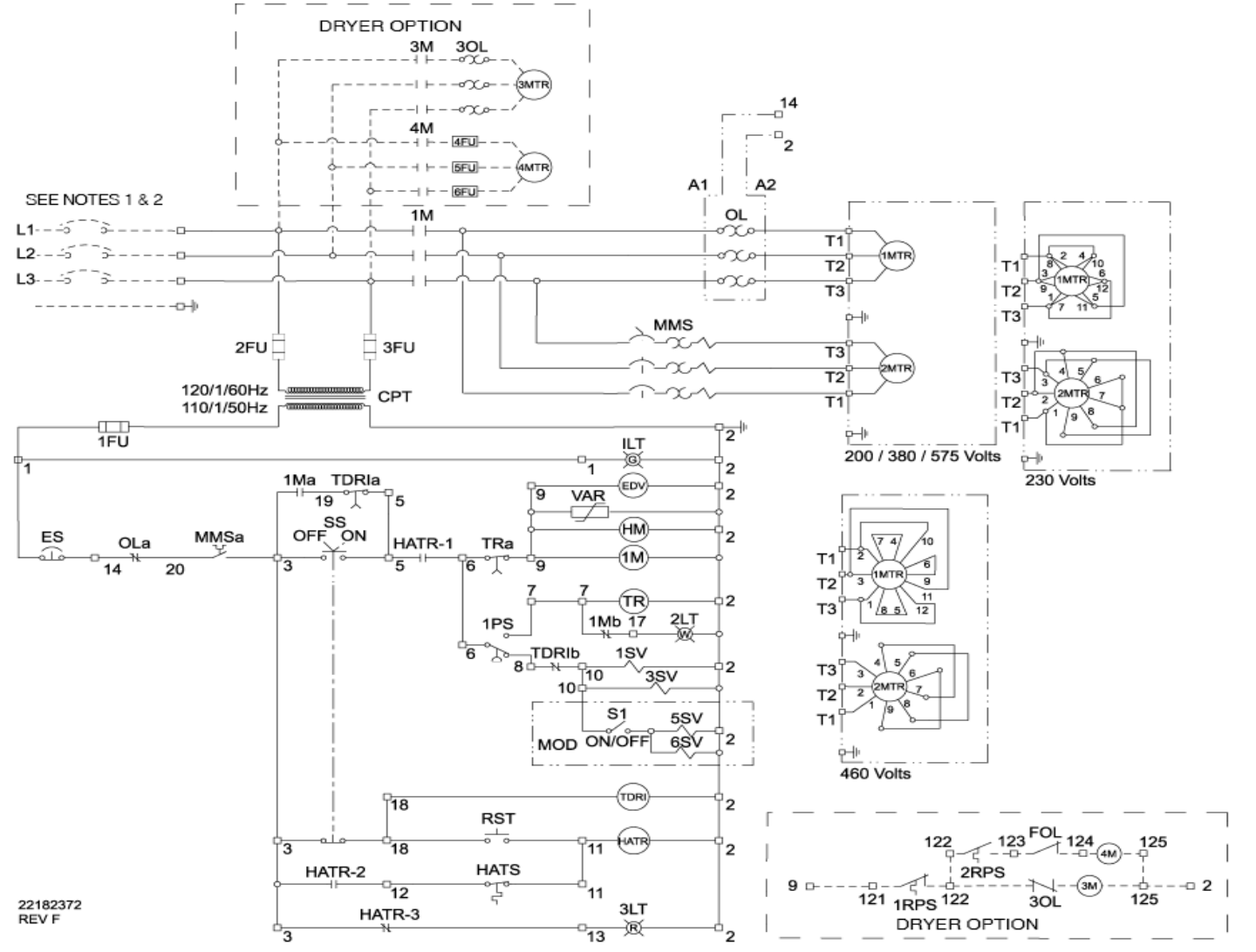
SSR UP6 15-30 FV
SSR UP6 15-30 FV 1of2 Page 43
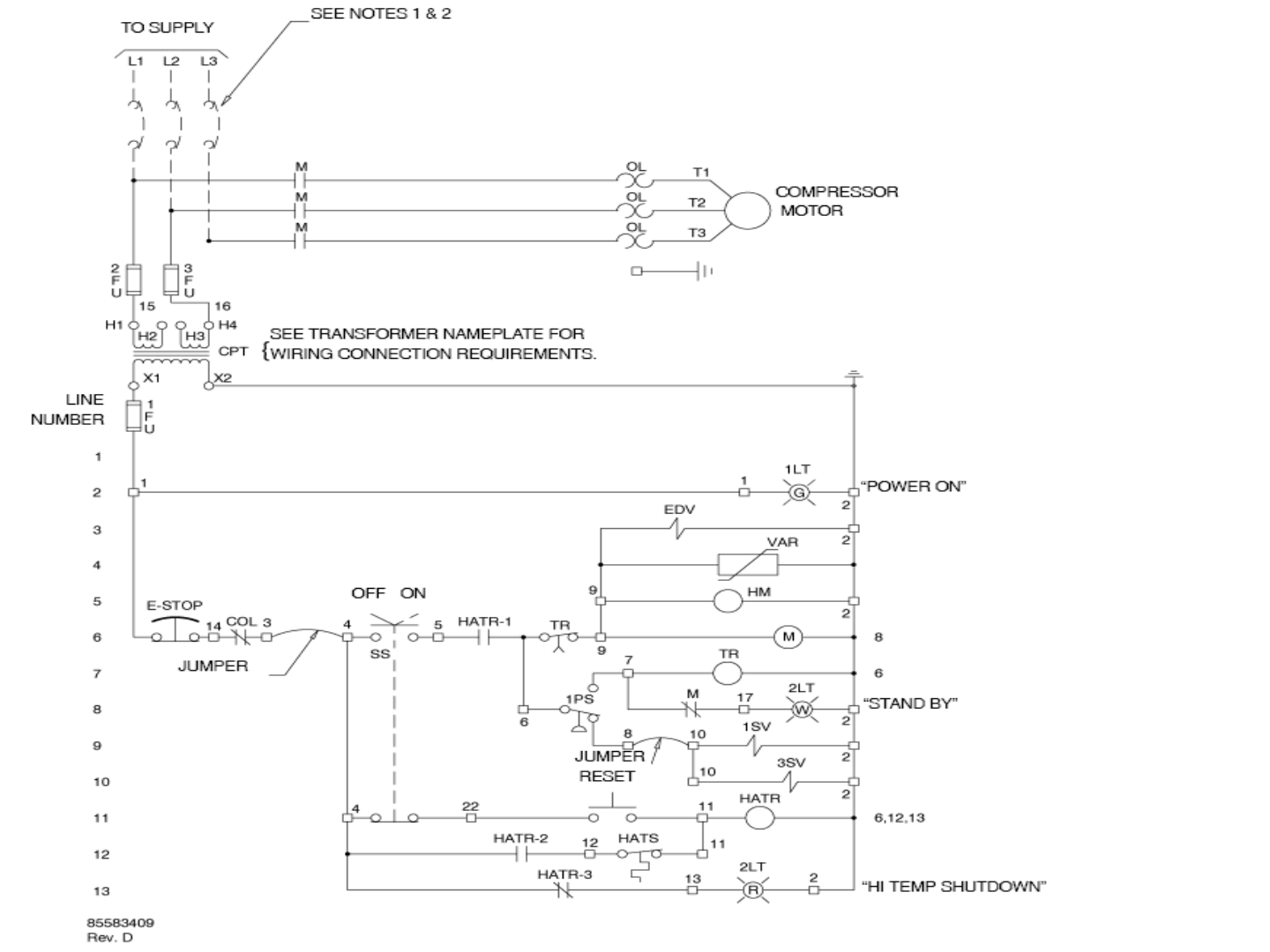
SSR UP6 15-30 FV
SSR UP6 15-30 FV 2of2 Page 44
Guidance only; connections may differ with date, model, type, variant, special, custom or concession builds.
This information is intended to be used in conjunction with the compressor’s original control circuit diagram.
1M 0 VAC
+VDC
Load Enable
Load/Unload
VFD/fixed
IN
NO
C
NC
NO
C
NC
RUN
ALARM
READY
OUT
V
SEQ CONT
LOAD UNL
GND
D11
D12
+20V
V
1
2
3
4
5
6
2
1
LED 5 VFD
LED 2 LOAD
LED 1 SEQ
LED 4
READY
LED 3
RUN
C03
C01
C02
C04
C05
IR-PCB
1
2
3
4
5
6
V1
X4I
COMPRESSOR #1
X01 TERMINAL
Refer to the X4I Overview Drawing
for the X4I Compressor 2 through 4
terminal connections
E-STOP
110VAC
HATR
Contact
Restart TD
Relay
Contact
ON OFF
OL
1PS
To TR Relay
To 1M Contact
To 2M Contact
1M
Contact
SSR UP6 15-30 SD
SSR UP6 15-30 SD 1of2 Page 45
SSR UP6 15-30 SD
SSR UP6 15-30 SD 2of2 Page 46
Guidance only; connections may differ with date, model, type, variant, special, custom or concession builds.
This information is intended to be used in conjunction with the compressor’s original control circuit diagram.
1M 0 VAC
+VDC
Load Enable
Load/Unload
VFD/fixed
IN
NO
C
NC
NO
C
NC
RUN
ALARM
READY
OUT
V
SEQ CONT
LOAD UNL
GND
D11
D12
+20V
V
1
2
3
4
5
6
2
1
LED 5 VFD
LED 2 LOAD
LED 1 SEQ
LED 4
READY
LED 3
RUN
C03
C01
C02
C04
C05
IR-PCB
1
2
3
4
5
6
V1
X4I
COMPRESSOR #1
X01 TERMINAL
Refer to the X4I Overview Drawing
for the X4I Compressor 2 through 4
terminal connections
E-STOP
110VAC
HATR
Contact
Restart TD
Relay
Contact
SS
ON OFF
OL
1PS
To TR Relay
To 1M Contact
To TDRI Contact
1M
Relay
Contact
TDRI
Relay
Contact
MMS
Contact
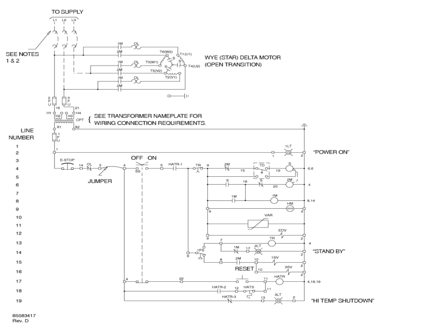
SSR UP6 40-50 FV
SSR UP6 40-50 FV 1of2 Page 47
SSR UP6 40-50 FV
SSR UP6 40-50 FV 2of2 Page 48
Guidance only; connections may differ with date, model, type, variant, special, custom or concession builds.
This information is intended to be used in conjunction with the compressor’s original control circuit diagram.
1M 0 VAC
+VDC
Load Enable
Load/Unload
VFD/fixed
IN
NO
C
NC
NO
C
NC
RUN
ALARM
READY
OUT
V
SEQ CONT
LOAD UNL
GND
D11
D12
+20V
V
1
2
3
4
5
6
2
1
LED 5 VFD
LED 2 LOAD
LED 1 SEQ
LED 4
READY
LED 3
RUN
C03
C01
C02
C04
C05
IR-PCB
1
2
3
4
5
6
V1
X4I
COMPRESSOR #1
X01 TERMINAL
Refer to the X4I Overview Drawing
for the X4I Compressor 2 through 4
terminal connections
E-STOP
110VAC
HATR
Contact
Restart TD
Relay
Contact
SS
ON OFF
OL
1PS
To TR Relay
To 1M Contact
To 2M Contact
1M
Relay
Contact
TDRI
Relay
Contact
MMS
Contact
1M
Contact
SSR UP6 40-50 SD
SSR UP6 40-50 SD 1of2 Page 49
SSR UP6 40-50 SD
SSR UP6 40-50 SD 2of2 Page 50

Guidance only; connections may differ with date, model, type, variant, special, custom or concession builds.
This information is intended to be used in conjunction with the compressor’s original control circuit diagram.
+VDC
Load Enable
Load/Unload
VFD/fixed
IN
NO
C
NC
NO
C
NC
RUN
ALARM
READY
OUT
V
SEQ CONT
LOAD UNL
GND
D11
D12
+20V
V
1
2
3
4
5
6
2
1
LED 5 VFD
LED 2 LOAD
LED 1 SEQ
LED 4
READY
LED 3
RUN
C03
C01
C02
C04
C05
IR-PCB
1
2
3
4
5
6
V1
X4I
COMPRESSOR #1
X01 TERMINAL
Refer to the X4I Overview Drawing
for the X4I Compressor 2 through 4
terminal connections 0 VAC
110VAC
PS
STOL
CR
Contact
HATS
M
To 1M Contact
To CR Relay
E-STOP To HM
To EDV
To M
UP6 5-15 FV 1PH 60Hz
UP6 5-15 FV 1PH 60Hz 1of2 Page 51
UP6 5-15 FV 1PH 60Hz
UP6 5-15 FV 1PH 60Hz 2of2 Page 52
+VDC
Load Enable
Load/Unload
VFD/fixed
IN
NO
C
NC
NO
C
NC
RUN
ALARM
READY
OUT
V
SEQ CONT
LOAD UNL
GND
D11
D12
+20V
V
1
2
3
4
5
6
2
1
LED 5 VFD
LED 2 LOAD
LED 1 SEQ
LED 4
READY
LED 3
RUN
C03
C01
C02
C04
C05
IR-PCB
1
2
3
4
5
6
V1
X4I
COMPRESSOR #1
X01 TERMINAL
Refer to the X4I Overview Drawing
for the X4I Compressor 2 through 4
terminal connections 0 VAC
110VAC
PS
STOL
CR
Contact
HATS
M
To 1M Contact
To CR Relay
E-STOP To HM
To EDV
To M
UP6 5-15 FV 3PH 60Hz
UP6 5-15 FV 3PH 60Hz 1of2 Page 53
UP6 5-15 FV 3PH 60Hz
UP6 5-15 FV 3PH 60Hz 2of2 Page 54

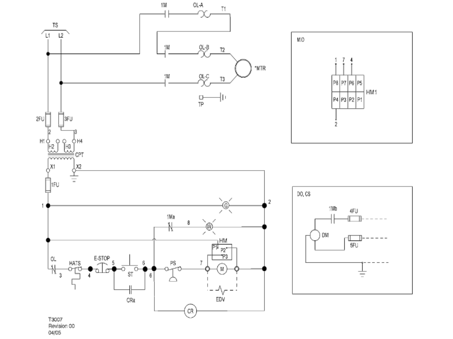
0 VAC
110VAC
PS
ST
CR
Contact
HATS
1M
To 1M Contact
To CR Relay
To HM
To EDV
To 1M/1S/2M Contacts
To TD Relay
Guidance only; connections may differ with date, model, type, variant, special, custom or concession builds.
This information is intended to be used in conjunction with the compressor’s original control circuit diagram.
+VDC
Load Enable
Load/Unload
VFD/fixed
IN
NO
C
NC
NO
C
NC
RUN
ALARM
READY
OUT
V
SEQ CONT
LOAD UNL
GND
D11
D12
+20V
V
1
2
3
4
5
6
2
1
LED 5 VFD
LED 2 LOAD
LED 1 SEQ
LED 4
READY
LED 3
RUN
C03
C01
C02
C04
C05
IR-PCB
1
2
3
4
5
6
V1
X4I
COMPRESSOR #1
X01 TERMINAL
Refer to the X4I Overview Drawing
for the X4I Compressor 2 through 4
terminal connections
E-STOP
1M
Contact
OL
UP6 5-15 SD 3PH 60Hz
UP6 5-15 SD 3PH 60Hz 1of2 Page 55
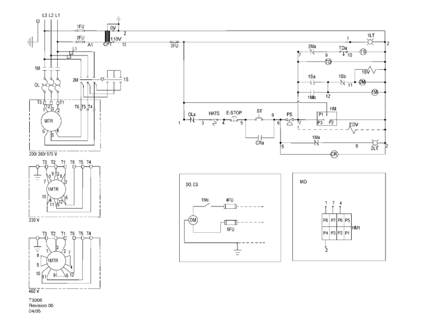
UP6 5-15 SD 3PH 60Hz
UP6 5-15 SD 3PH 60Hz 2of2 Page 56
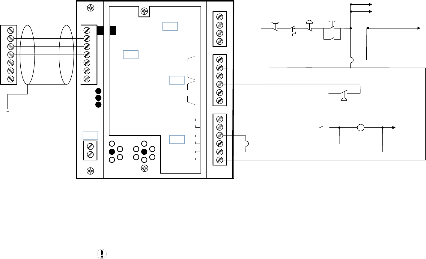
Guidance only; connections may differ with date, model, type, variant, special, custom or concession builds.
This information is intended to be used in conjunction with the compressor’s original control circuit diagram.
+VDC
Load Enable
Load/Unload
VFD/fixed
IN
NO
C
NC
NO
C
NC
RUN
ALARM
READY
OUT
V
SEQ CONT
LOAD UNL
GND
D11
D12
+20V
V
1
2
3
4
5
6
2
1
LED 5 VFD
LED 2 LOAD
LED 1 SEQ
LED 4
READY
LED 3
RUN
C03
C01
C02
C04
C05
IR-PCB
1
2
3
4
5
6
V1
X4I
COMPRESSOR #1
X01 TERMINAL
Refer to the X4I Overview Drawing
for the X4I Compressor 2 through 4
terminal connections 0 VAC
110VAC
P
ST
CR
Contact
HATS
KM
To KM1 Contact
To CR Relay
To HM
To EDV
KM1/KM2/KM3 Contacts
To KM1
MOL
Contact E-STOP
KM1
Contact
UP6 5-15 FV 3PH 50Hz
UP6 5-15 FV 3PH 50Hz 1of2 Page 57
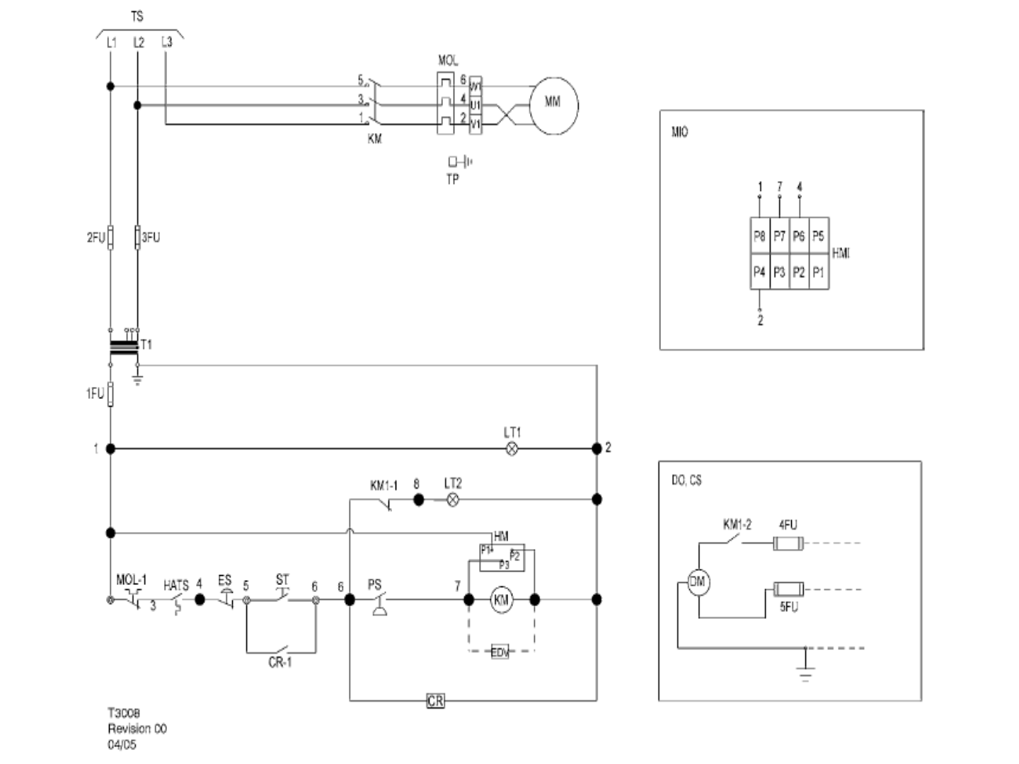
UP6 5-15 FV 3PH 50Hz
UP6 5-15 FV 3PH 50Hz 2of2 Page 58
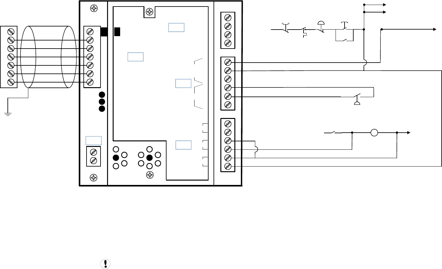
Guidance only; connections may differ with date, model, type, variant, special, custom or concession builds.
This information is intended to be used in conjunction with the compressor’s original control circuit diagram.
+VDC
Load Enable
Load/Unload
VFD/fixed
IN
NO
C
NC
NO
C
NC
RUN
ALARM
READY
OUT
V
SEQ CONT
LOAD UNL
GND
D11
D12
+20V
V
1
2
3
4
5
6
2
1
LED 5 VFD
LED 2 LOAD
LED 1 SEQ
LED 4
READY
LED 3
RUN
C03
C01
C02
C04
C05
IR-PCB
1
2
3
4
5
6
V1
X4I
COMPRESSOR #1
X01 TERMINAL
Refer to the X4I Overview Drawing
for the X4I Compressor 2 through 4
terminal connections 0 VAC
110VAC
P
ST
CR
Contact
HATS
KM
To KM1 Contact
To CR Relay
To HM
To EDV
KM1/KM2/KM3 Contacts
To KM1
MOL
Contact E-STOP
KM1
Contact
UP6 5-15 SD 3PH 50Hz
UP6 5-15 SD 3PH 50Hz 1of2 Page 59
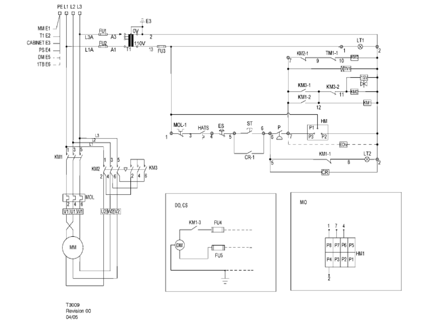
UP6 5-15 SD 3PH 50Hz
UP6 5-15 SD 3PH 50Hz 2of2 Page 60
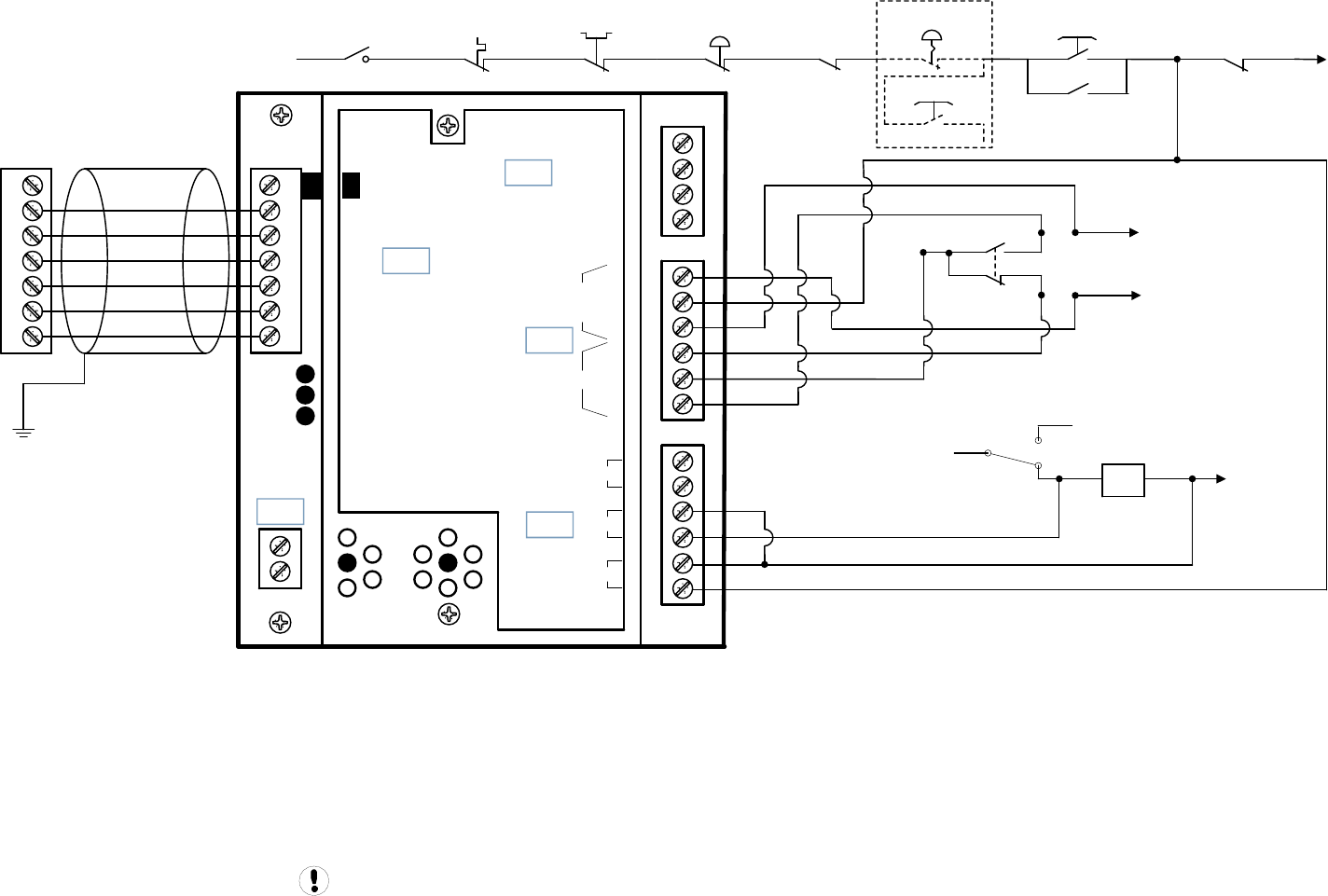
KM1 0 VAC
TM2
Contact
PTo TM2 Relay
To KM2 Contact
+VDC
Load Enable
Load/Unload
VFD/fixed
IN
NO
C
NC
NO
C
NC
RUN
ALARM
READY
OUT
V
SEQ CONT
LOAD UNL
GND
D11
D12
+20V
V
1
2
3
4
5
6
2
1
LED 5 VFD
LED 2 LOAD
LED 1 SEQ
LED 4
READY
LED 3
RUN
C03
C01
C02
C04
C05
IR-PCB
1
2
3
4
5
6
V1
X4I
COMPRESSOR #1
X01 TERMINAL
Refer to the X4I Overview Drawing
for the X4I Compressor 2 through 4
terminal connections
To TM3 Contact
To AS Switch
K2 Contact
TM2 Contact
SS
MOL
Contact
110VAC
ST
CR
Contact
HAT
MCB2
Contact E-STOP
ST
(OPT)
K3
Contact
Guidance only; connections may differ with date, model, type, variant, special, custom or concession builds.
This information is intended to be used in conjunction with the compressor’s original control circuit diagram.
SSR M15-22c 20-30HP XF EP HP HXP 50-60Hz
SSR M15-22c 20-30HP XF EP HP HXP 50-60Hz 1of2 Page 61
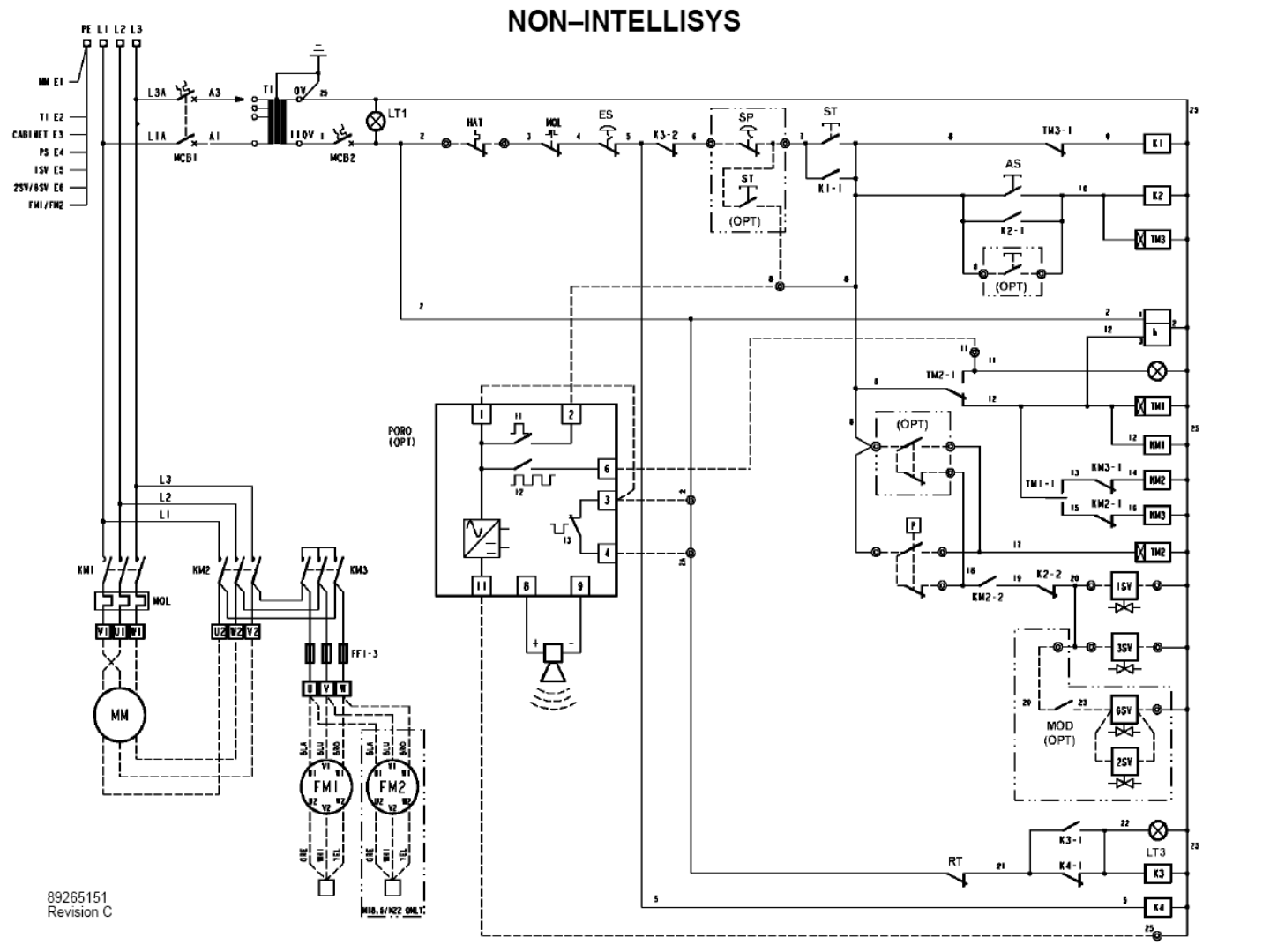
SSR M15-22c 20-30HP XF EP HP HXP 50-60Hz
SSR M15-22c 20-30HP XF EP HP HXP 50-60Hz 2of2 Page 62
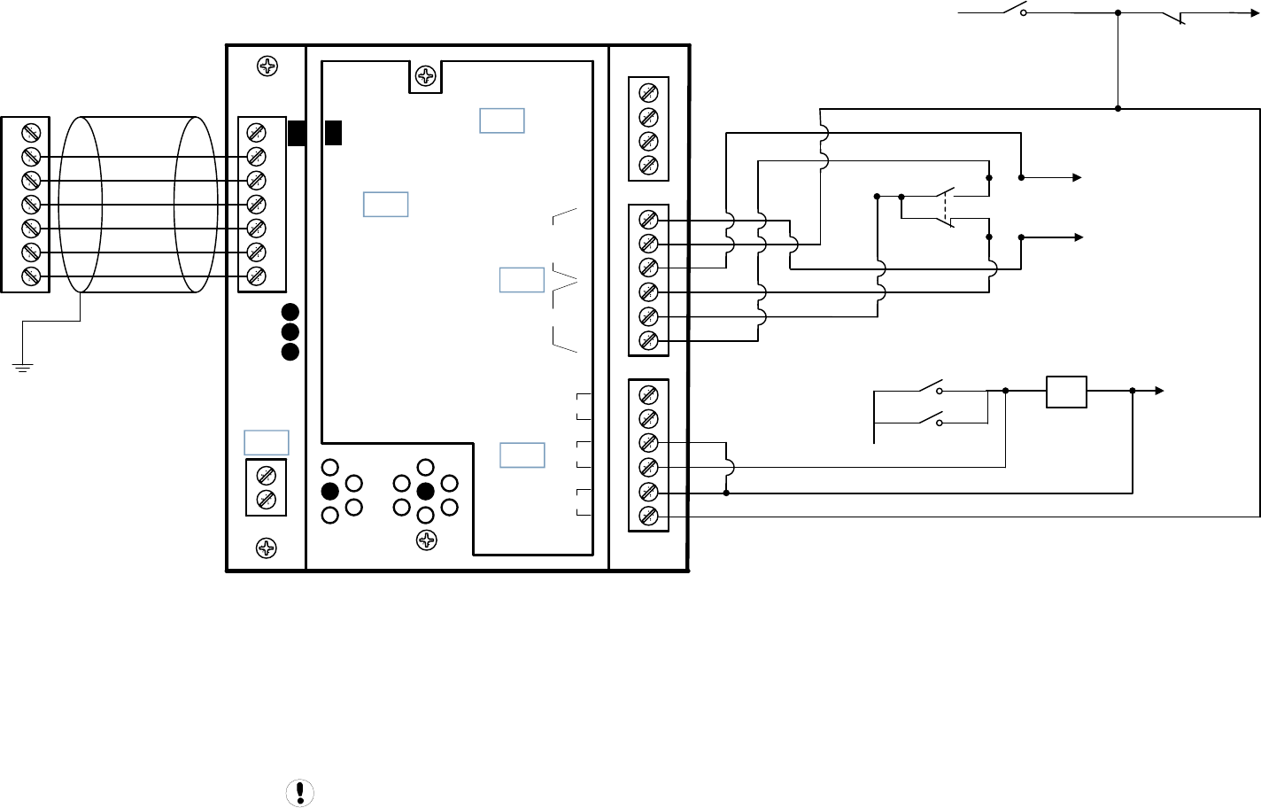
KM1 0 VAC
KM1 Contact
PTo 2TR Relay
To KM2 Contact
+VDC
Load Enable
Load/Unload
VFD/fixed
IN
NO
C
NC
NO
C
NC
RUN
ALARM
READY
OUT
V
SEQ CONT
LOAD UNL
GND
D11
D12
+20V
V
1
2
3
4
5
6
2
1
LED 5 VFD
LED 2 LOAD
LED 1 SEQ
LED 4
READY
LED 3
RUN
C03
C01
C02
C04
C05
IR-PCB
1
2
3
4
5
6
V1
X4I
COMPRESSOR #1
X01 TERMINAL
Refer to the X4I Overview Drawing
for the X4I Compressor 2 through 4
terminal connections
To 2TR Contact
To 1VAC Contact
To 3OP Contact
48VAC
K1
Contact
KM3 Contact
Guidance only; connections may differ with date, model, type, variant, special, custom or concession builds.
This information is intended to be used in conjunction with the compressor’s original control circuit diagram.
M37-50
M37-50 1of2 Page 63
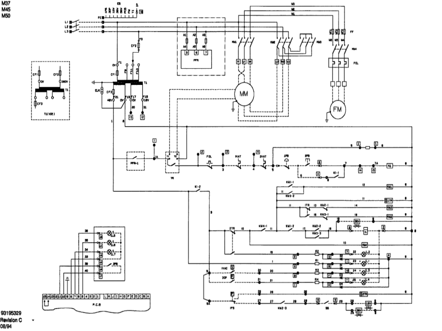
M37-50
M37-50 2of2 Page 64
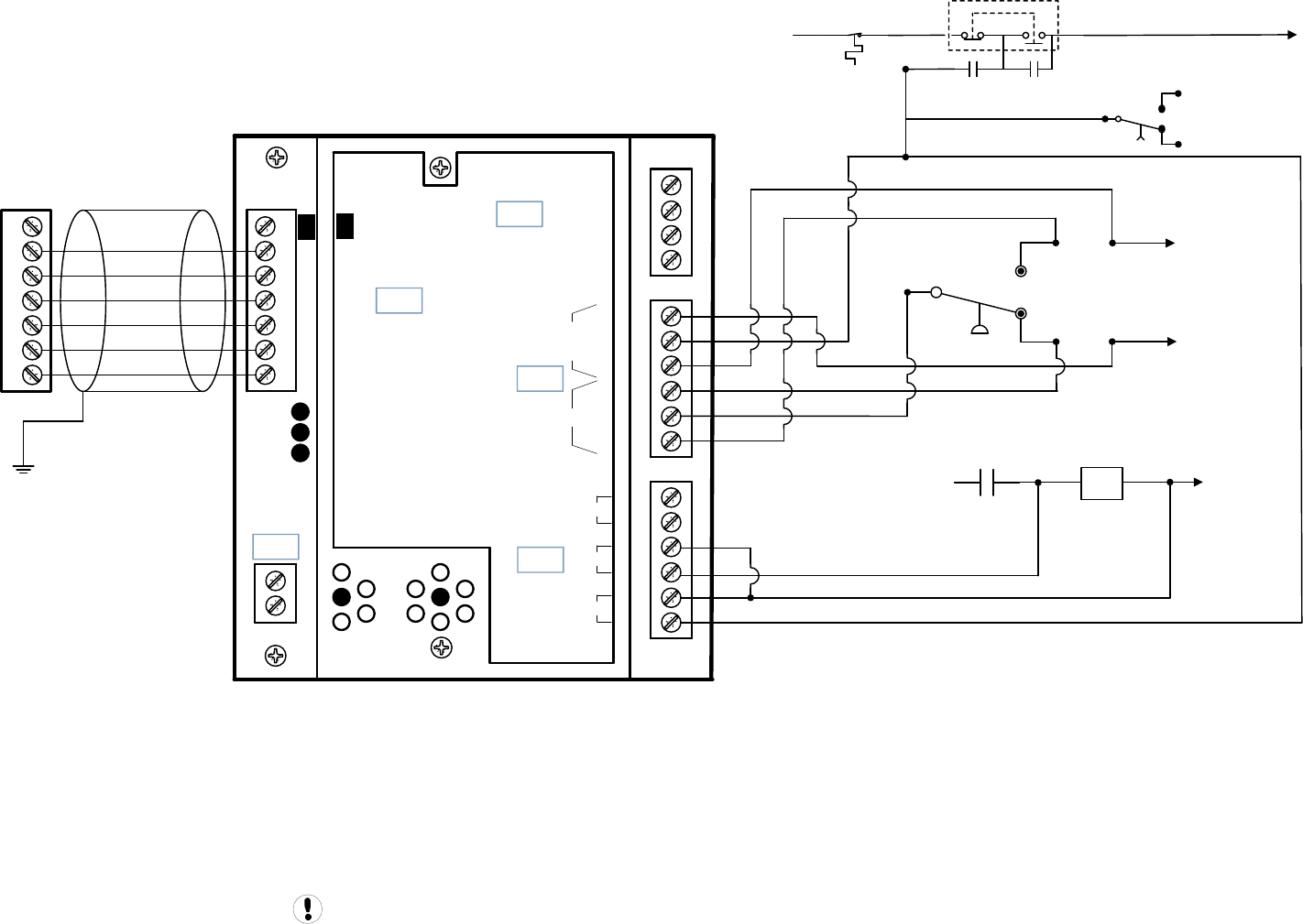
110VAC
CR
Contact
HATS
CR
Contact
PUSH
STOP PULL
START
1M 0 VAC
+VDC
Load Enable
Load/Unload
VFD/fixed
IN
NO
C
NC
NO
C
NC
RUN
ALARM
READY
OUT
V
SEQ CONT
LOAD UNL
GND
D11
D12
+20V
V
1
2
3
4
5
6
2
1
LED 5 VFD
LED 2 LOAD
LED 1 SEQ
LED 4
READY
LED 3
RUN
C03
C01
C02
C04
C05
IR-PCB
1
2
3
4
5
6
V1
X4I
COMPRESSOR #1
X01 TERMINAL
Refer to the X4I Overview Drawing
for the X4I Compressor 2 through 4
terminal connections
1PS
To 1TD Relay
To 1M Contact
1M
Contact
To 1CR Relay
1TD Contact
Guidance only; connections may differ with date, model, type, variant, special, custom or concession builds.
This information is intended to be used in conjunction with the compressor’s original control circuit diagram.
EP 20-30 ESP FV
EP 20-30 ESP FV 1of2 Page 65
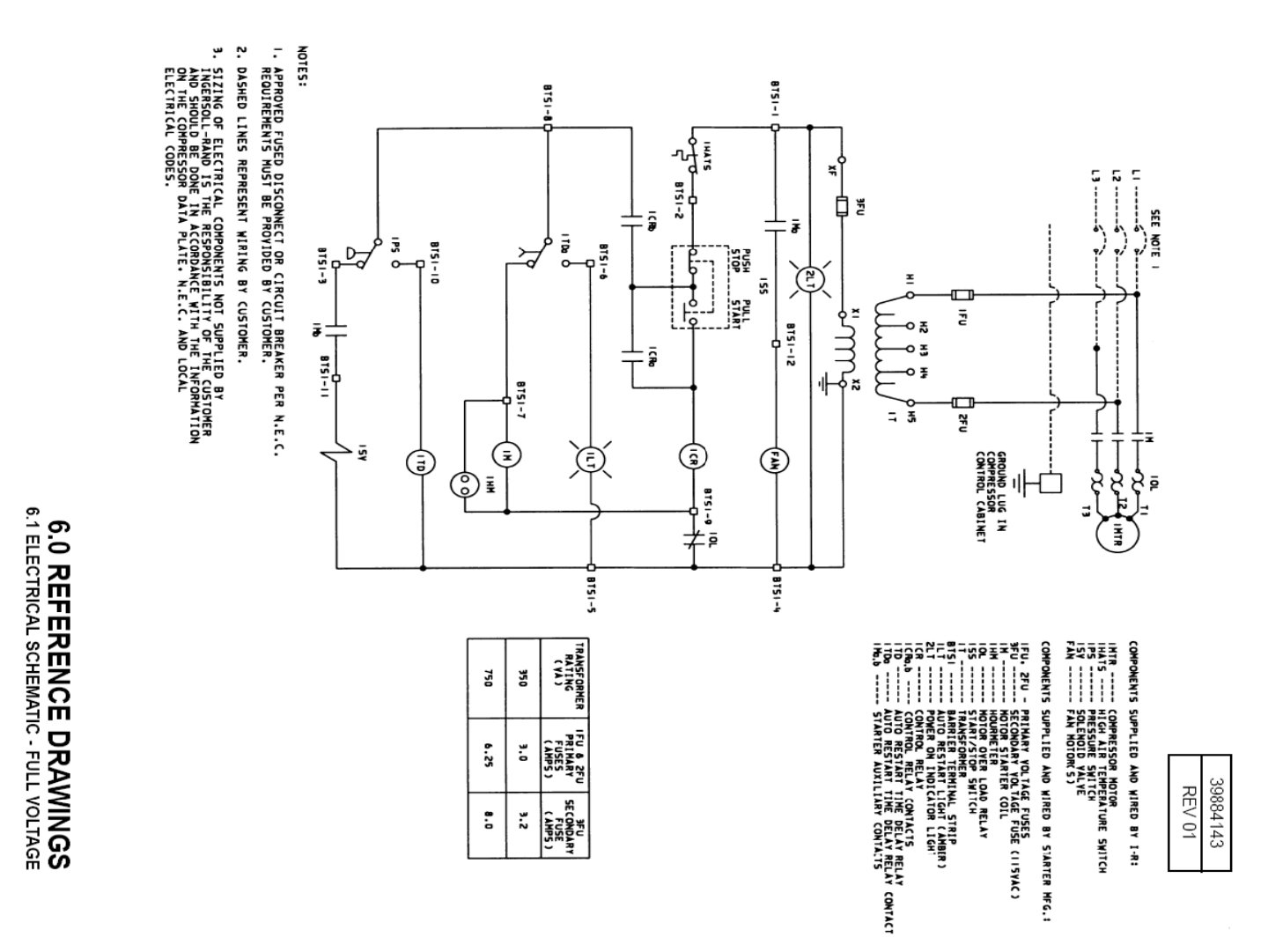
EP 20-30 ESP FV
EP 20-30 ESP FV 2of2 Page 66
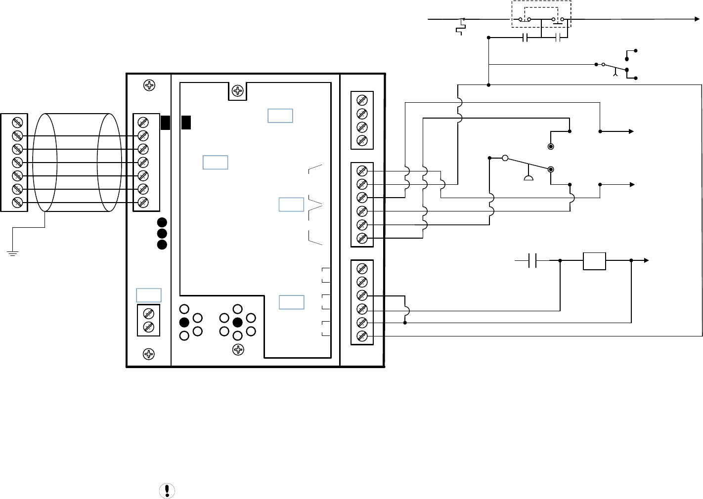
110VAC
CR
Contact
HATS
CR
Contact
PUSH
STOP PULL
START
1M 0 VAC
+VDC
Load Enable
Load/Unload
VFD/fixed
IN
NO
C
NC
NO
C
NC
RUN
ALARM
READY
OUT
V
SEQ CONT
LOAD UNL
GND
D11
D12
+20V
V
1
2
3
4
5
6
2
1
LED 5 VFD
LED 2 LOAD
LED 1 SEQ
LED 4
READY
LED 3
RUN
C03
C01
C02
C04
C05
IR-PCB
1
2
3
4
5
6
V1
X4I
COMPRESSOR #1
X01 TERMINAL
Refer to the X4I Overview Drawing
for the X4I Compressor 2 through 4
terminal connections
1PS
To 1TD Relay
To 2M Contact
1M
Contact
To 1CR Relay
1TD Contact
EP 20-30 ESP SD
Guidance only; connections may differ with date, model, type, variant, special, custom or concession builds.
This information is intended to be used in conjunction with the compressor’s original control circuit diagram.
EP 20-30 ESP SD 1of2 Page 67
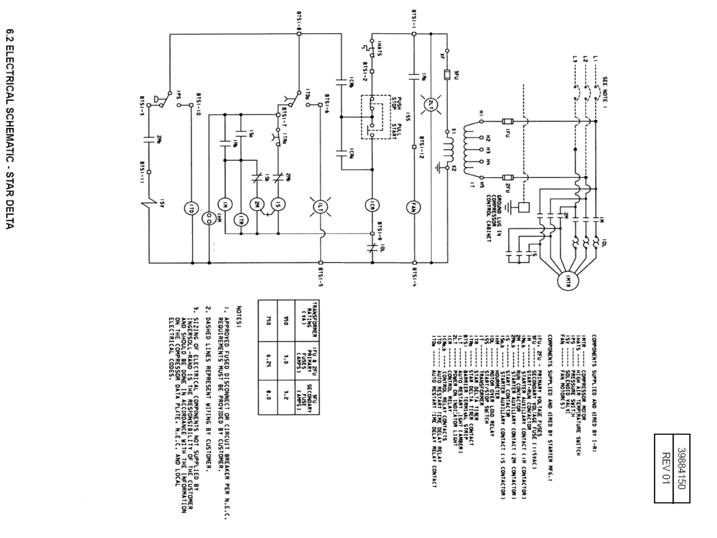
EP 20-30 ESP SD
EP 20-30 ESP SD 2of2 Page 68

X4I Interconnect To Ingersoll Rand Intellisys SGN / SGNe Controlled Compressors
Refer to the X4I Overview Drawing for the X4I Compressor 2 through 4 X01 to IR-PCB terminal connections
For SGN/SGNe Intellisys Controlled Machines:
The SI1 interface (CCN: 42425710) must be used to allow the SGN/SGNe Controller to be sequenced/controlled by the X4I
The 'SEQUENCER' setting of the Intellisys controller must be set to 'ON'.
Auto Restart must be turned 'ON’ to allow the machines to stop in Auto restart when unloaded by the X4I.
The Intellisys must be run in the Online/Offline regulation mode. Do not use Modulation or ACS.
Check the Intellisys software revision level. Always update to the latest revision prior to operation.
Drawing Notes For Nirvana Machines:
Note: The Nirvana Target Pressure “MUST” be set equal to the Midpoint of the X4I pressure control band.
Refer to the X4I Overview Drawing for the X4I Compressor 2 through 4 X01 to IR-PCB terminal connections
Guidance only; connections may differ with date, model, type, variant, special, custom or concession builds. This information is intended to be
used in conjunction with the compressor’s original control circuit diagram.
X4I Interconnect To Ingersoll Rand Intellisys SGN / SGNe Controlled Compressors Page 69
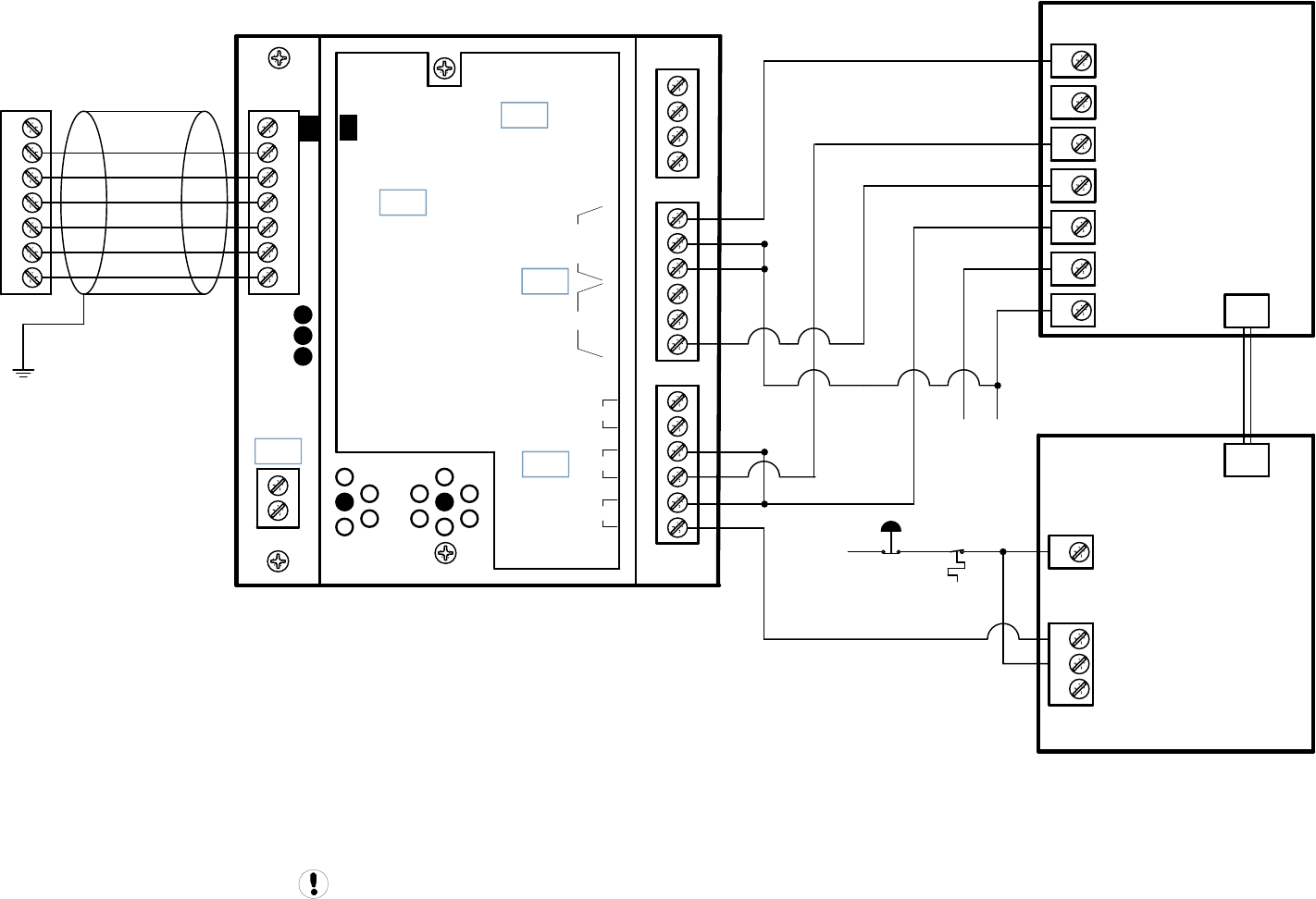
+VDC
Load Enable
Load/Unload
VFD/fixed
IN
NO
C
NC
NO
C
NC
RUN
ALARM
READY
OUT
V
SEQ CONT
LOAD UNL
GND
D11
D12
+20V
V
1
2
3
4
5
6
2
1
LED 5 VFD
LED 2 LOAD
LED 1 SEQ
LED 4
READY
LED 3
RUN
C03
C01
C02
C04
C05
IR-PCB
1
2
3
4
5
6
V1
X4I
COMPRESSOR #1
X01 TERMINAL
Refer to the X4I Overview Drawing
for the X4I Compressor 2 through 4
terminal connections
3
2
1
110VAC E-STOP
HATS
SGN/
SGNe
P1
1
5
4
6
7
3
2
1
NH
110 VAC
Supply
Hot
Neutral
Neutral
Remote Load / Unload
Run
Remote Load Enable
COM
COM
Intellisys Controller
Sequence Interface 1
Guidance only; connections may differ with date, model, type, variant, special, custom or concession builds.
This information is intended to be used in conjunction with the compressor’s original control circuit diagram.
SGN/
SGNe
P2
Nirvana SGN/SGNe
Nirvana SGN/SGNe 1of3 Page 70
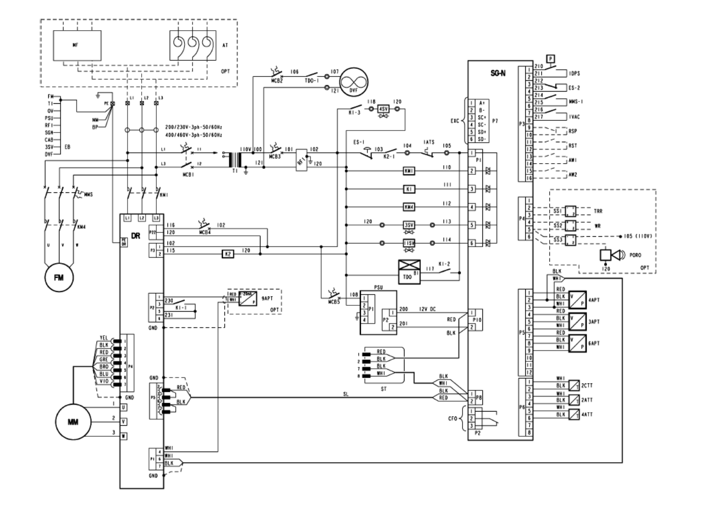
Nirvana SGN/SGNe
Nirvana SGN/SGNe 2of3 Page 71
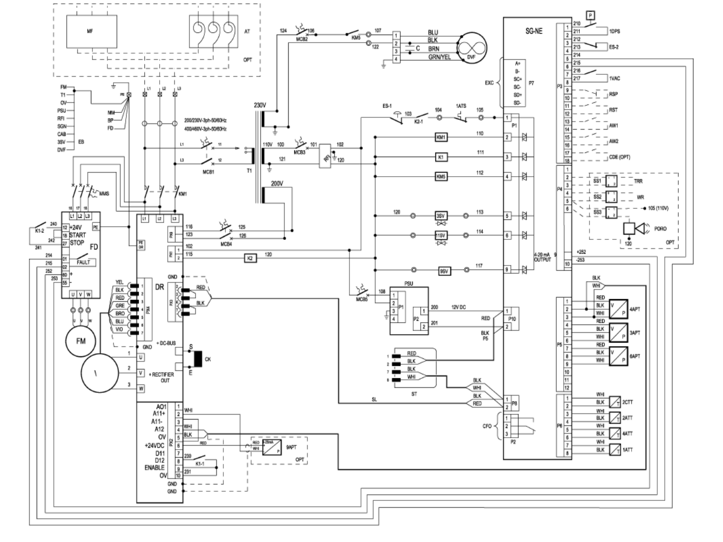
Nirvana SGN/SGNe
Nirvana SGN/SGNe 3of3 Page 72
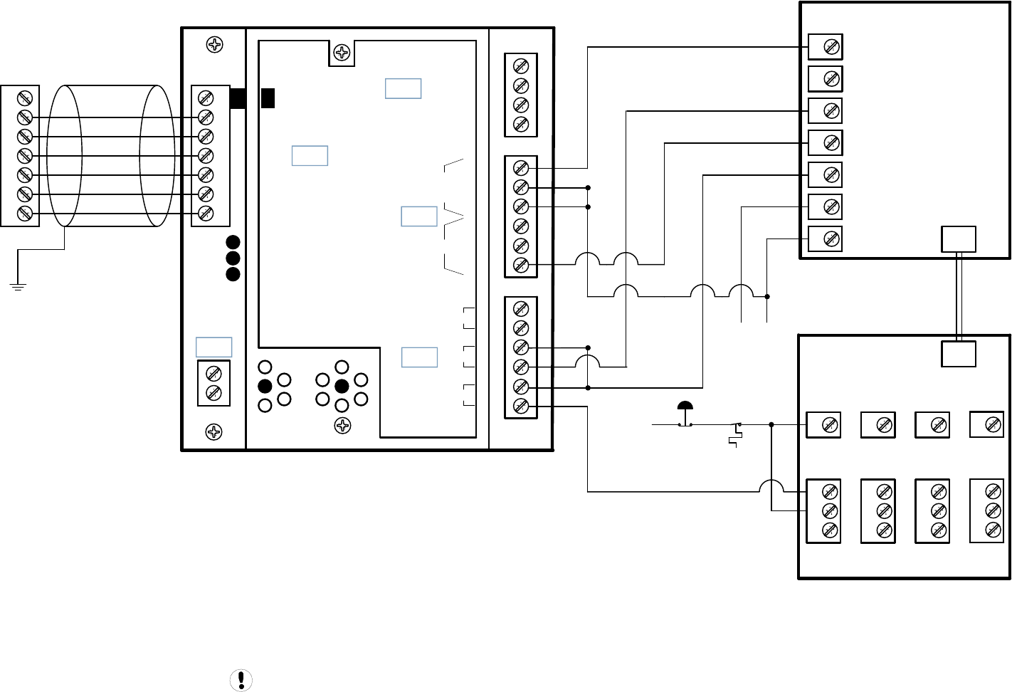
+VDC
Load Enable
Load/Unload
VFD/fixed
IN
NO
C
NC
NO
C
NC
RUN
ALARM
READY
OUT
V
SEQ CONT
LOAD UNL
GND
D11
D12
+20V
V
1
2
3
4
5
6
2
1
LED 5 VFD
LED 2 LOAD
LED 1 SEQ
LED 4
READY
LED 3
RUN
C03
C01
C02
C04
C05
IR-PCB
1
2
3
4
5
6
V1
X4I
COMPRESSOR #1
X01 TERMINAL
Refer to the X4I Overview Drawing
for the X4I Compressor 2 through 4
terminal connections
1
2
3
110VAC E-STOP
Redeye
BTS2-
HATS
34
33
32
9
10
11
Redeye
BTS1-
SE
DSA
J5
SE
ESA/UP
J5
34 36 7
3
2
1
SG
P2
SG
P1
1
5
4
6
7
3
2
1
NH
110 VAC
Supply
Hot
Neutral
Neutral
Remote Load / Unload
Run
Remote Load Enable
COM
COM
SE
ESA/UP
J5
SE
DSA
J5
Intellisys Controller
Sequence Interface 1
Guidance only; connections may differ with date, model, type, variant, special, custom or concession builds.
This information is intended to be used in conjunction with the compressor’s original control circuit diagram.
SI1 Interface to Redeye, SE, SG Controllers
SI1 Interface to Redeye, SE, SG Controllers Page 73

X4I Interconnect To Ingersoll Rand Intellisys S3
Refer to the X4I Overview Drawing for the X4I Compressor 2 through 4 X01 to IR-PCB terminal connections
For All S3 Intellisys Controlled Machines:
The 'REMOTE CONTROL' setting “RC” of the Intellisys controller must be set to 'ON'.
Auto Restart must be turned 'ON’ to allow the machines to stop in Auto restart when unloaded by the X4I.
The Intellisys must be run in the Online/Offline regulation mode. Do not use Modulation.
Check the Intellisys software revision level. Always update to the latest revision prior to operation.
Drawing Notes For Intellisys S3 Machines:
Note: R1 Relay - IR CCN: 39403290
Note: R1 Relay Base – IR CCN: 39125091
Guidance only; connections may differ with date, model, type, variant, special, custom or concession builds. This information is intended to
be used in conjunction with the compressor’s original control circuit diagram.
X4I Interconnect To Ingersoll Rand Intellisys S3 Page 74
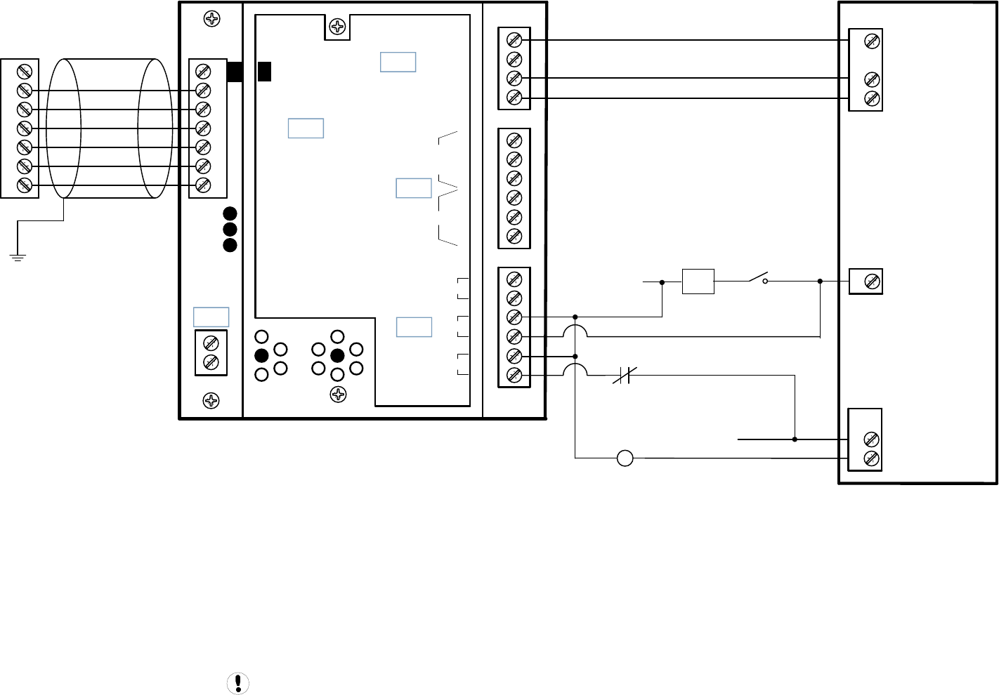
KM1
0VAC
3
4
110VAC
1
7
8
X02
X03
X04
2
Guidance only; connections may differ with date, model, type, variant, special, custom or concession builds.
This information is intended to be used in conjunction with the compressor’s original control circuit diagram.
+VDC
Load Enable
Load/Unload
VFD/fixed
IN
NO
C
NC
NO
C
NC
RUN
ALARM
READY
OUT
V
SEQ CONT
LOAD UNL
GND
D11
D12
+20V
V
1
2
3
4
5
6
2
1
LED 5 VFD
LED 2 LOAD
LED 1 SEQ
LED 4
READY
LED 3
RUN
C03
C01
C02
C04
C05
IR-PCB
1
2
3
4
5
6
V1
X4I
COMPRESSOR #1
X01 TERMINAL
Refer to the X4I Overview Drawing
for the X4I Compressor 2 through 4
terminal connections
Intellisys S3
Remote Load/Unload
Remote Load Enable
KM2
Contact
R1
Coil
R1
Contact
Intellisys S3
Intellisys S3 1of2 Page 75
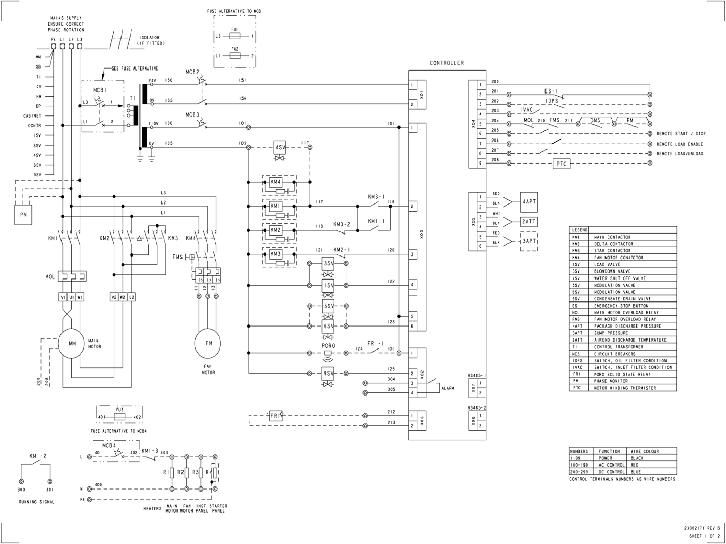
Intellisys S3
Intellisys S3 2of2 Page 76

X4I Interconnect To Ingersoll Rand Small Reciprocating Air Compressors
Refer to the X4I Overview Drawing for the X4I Compressor 2 through 4 X01 to IR-PCB terminal connections
For All Compressors:
Compressors to be connected must have automatic Start / Stop capability .
Drawing Notes For Pressure Switch Controller Machines:
Ensure each compressor is equipped with independent Excessive Pressure Shutdown Switch. An increase in pressure differential across air
treatment equipment can result in excess compressor discharge pressure. See Pages 84 and 85 for an example drawing. In most applications,
the model and type of pressure switch supplied with the compressor can be used as the Excessive Pressure Shutdown Switch. If this is specific
model/type of pressure switch is not readily available, any pressure switch can be utilized as long as it equals or exceeds the specifications of
the pressure switch found on the compressor.
Set the Excessive Pressure Shutdown Switch to “OPEN” 5 PSI less than the maximum discharge pressure recommended by the compressor
manufacturer.
Note: R1 and R2 Relay - IR CCN: 39403290
Note: R1 and R2 Relay Base – IR CCN: 39125091
Guidance only; connections may differ with date, model, type, variant, special, custom or concession builds. This information is intended to
be used in conjunction with the compressor’s original control circuit diagram.
X4I Interconnect to Ingersoll Rand Small Reciprocating Air Compressors Page 77
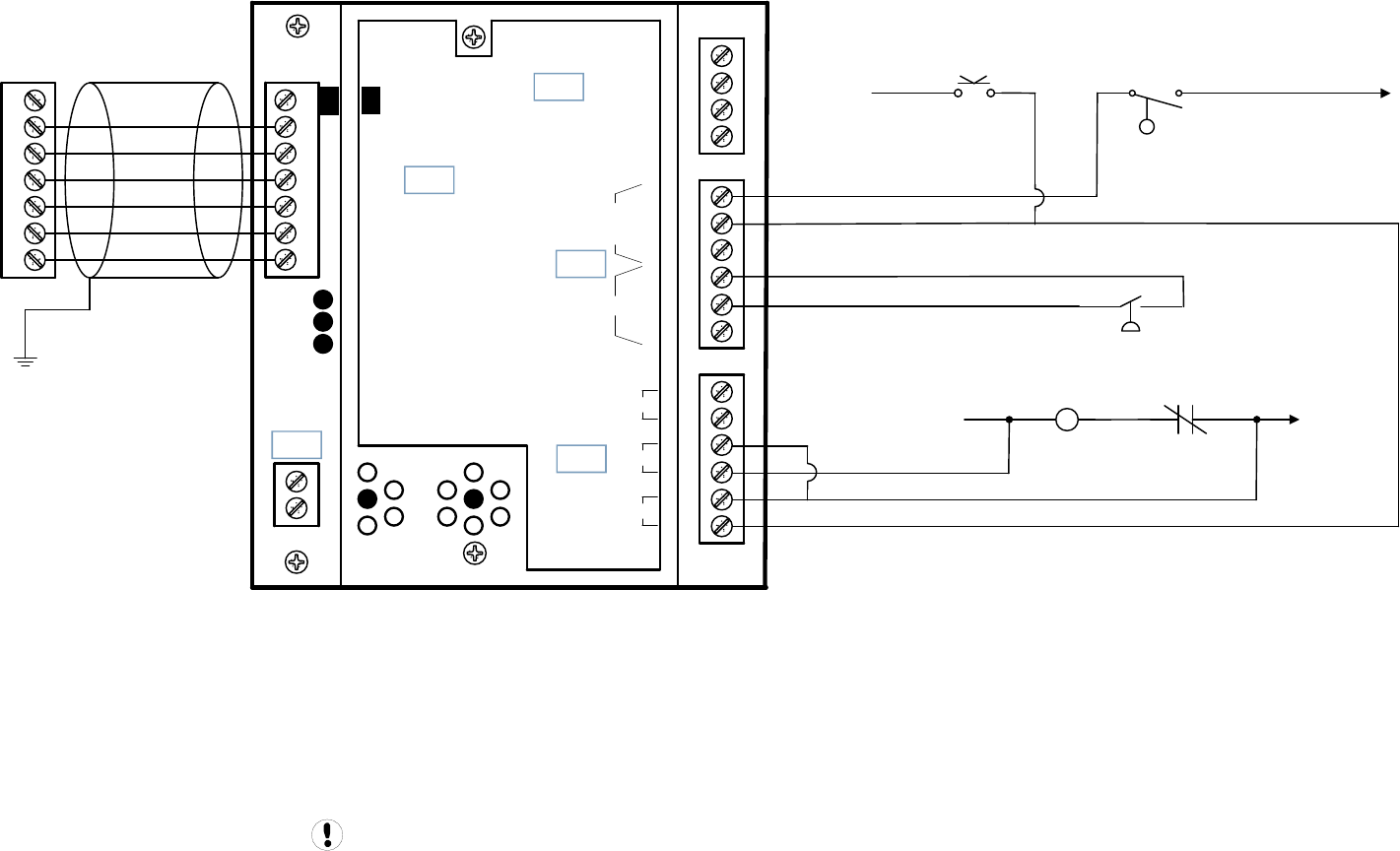
Guidance only; connections may differ with date, model, type, variant, special, custom or concession builds.
This information is intended to be used in conjunction with the compressor’s original control circuit diagram.
UP6RE 7.5–15 175, UP6RX 7.5–15 175
0 VAC
110VAC
P
M
+VDC
Load Enable
Load/Unload
VFD/fixed
IN
NO
C
NC
NO
C
NC
RUN
ALARM
READY
OUT
V
SEQ CONT
LOAD UNL
GND
D11
D12
+20V
V
1
2
3
4
5
6
2
1
LED 5 VFD
LED 2 LOAD
LED 1 SEQ
LED 4
READY
LED 3
RUN
C03
C01
C02
C04
C05
IR-PCB
1
2
3
4
5
6
V1
X4I
COMPRESSOR #1
X01 TERMINAL
Refer to the X4I Overview Drawing
for the X4I Compressor 2 through 4
terminal connections
SS
ON OFF
LOLS
To M
To ETM
OL
Contact
UP6RE 7.5–15 175, UP6RX 7.5–15 175 1of3 Page 78
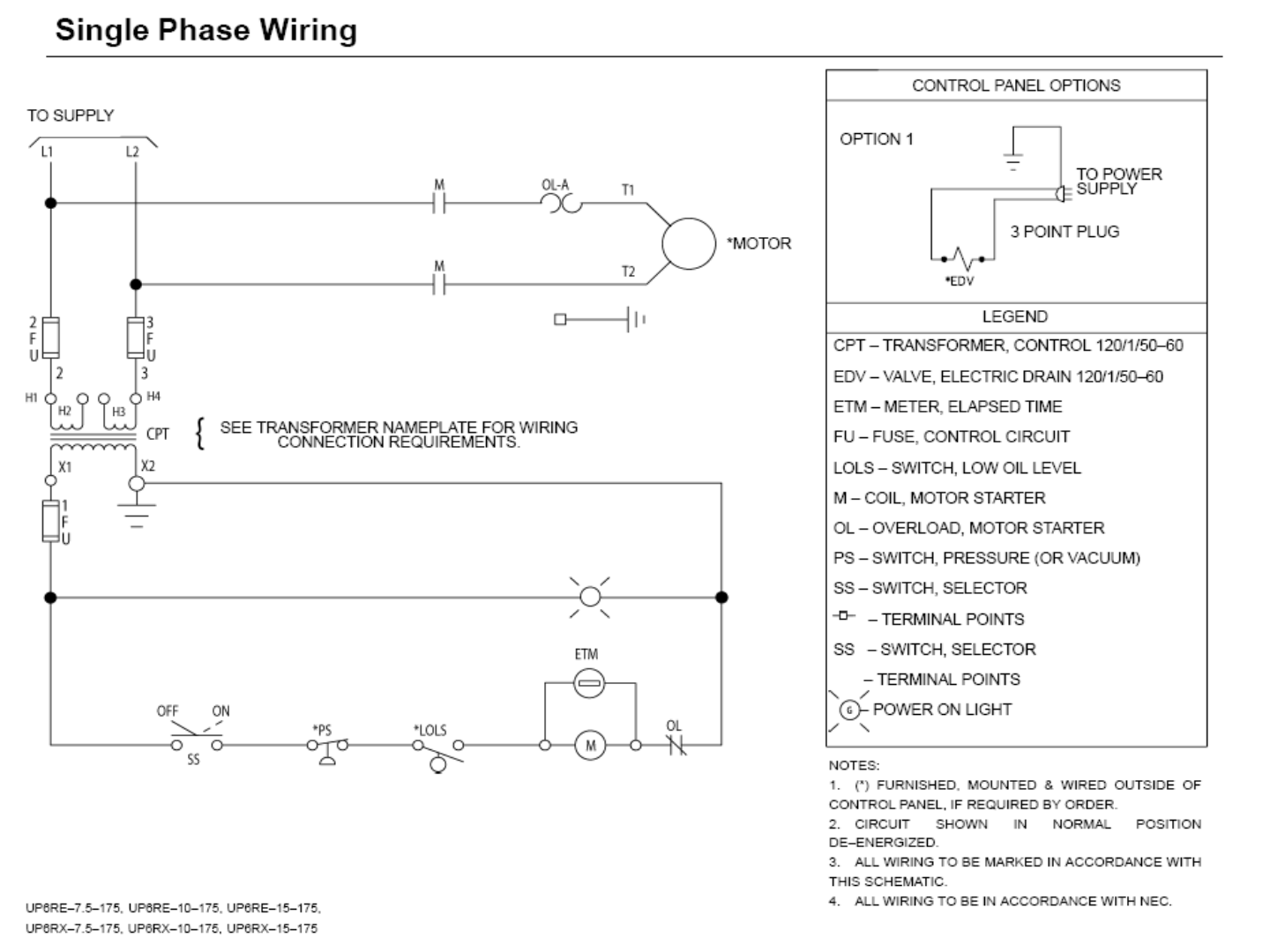
UP6RE 7.5–15 175, UP6RX 7.5–15 175
UP6RE 7.5–15 175, UP6RX 7.5–15 175 2of3 Page 79
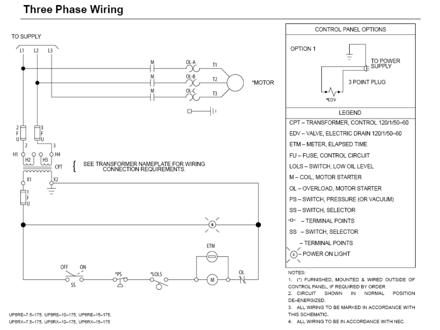
UP6RE 7.5–15 175, UP6RX 7.5–15 175
UP6RE 7.5–15 175, UP6RX 7.5–15 175 3of3 Page 80
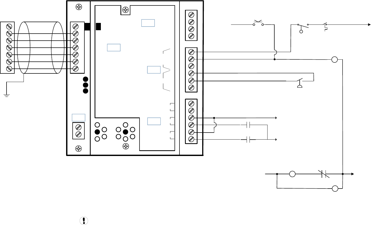
L2
L1
P
HATS
M
+VDC
Load Enable
Load/Unload
VFD/fixed
IN
NO
C
NC
NO
C
NC
RUN
ALARM
READY
OUT
V
SEQ CONT
LOAD UNL
GND
D11
D12
+20V
V
1
2
3
4
5
6
2
1
LED 5 VFD
LED 2 LOAD
LED 1 SEQ
LED 4
READY
LED 3
RUN
C03
C01
C02
C04
C05
IR-PCB
1
2
3
4
5
6
V1
X4I
COMPRESSOR #1
X01 TERMINAL
Refer to the X4I Overview Drawing
for the X4I Compressor 2 through 4
terminal connections
SS
ON OFF
LOLS
To M
OL
Contact
Models 2340, 2475, 2545, 7100, 15T & 3000
Guidance only; connections may differ with date, model, type, variant, special, custom or concession builds.
This information is intended to be used in conjunction with the compressor’s original control circuit diagram.
R1
R2
R2
R1
To Customer Supplied
External Neutral
To Customer Supplied
External 110VAC
Models 2340, 2475, 2545, 7100, 15T & 3000 10f3 Page 81
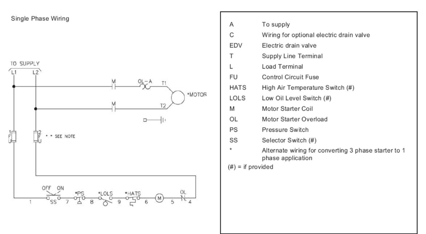
Models 2340, 2475, 2545, 7100, 15T & 3000
Models 2340, 2475, 2545, 7100, 15T & 3000 2of3 Page 82
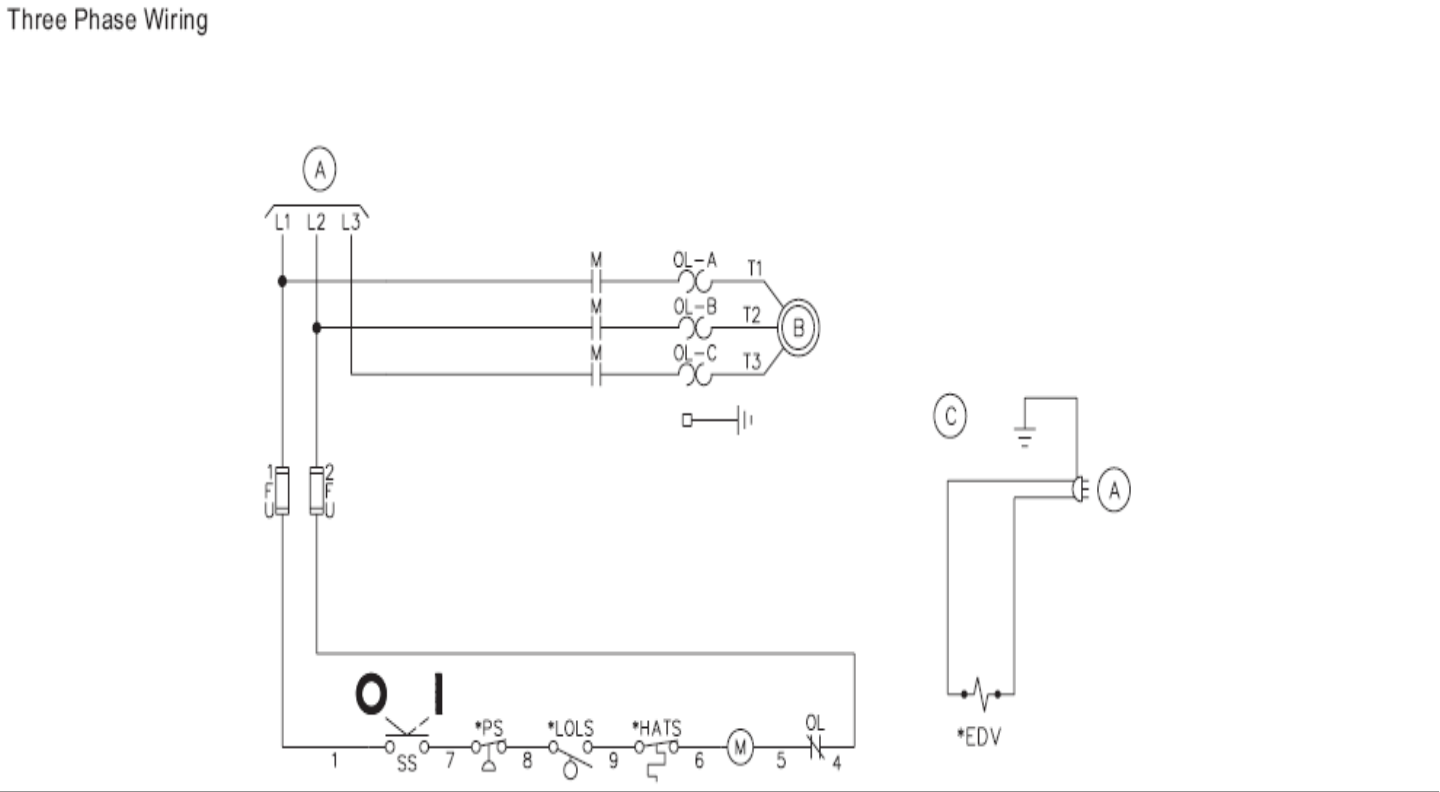
Models 2340, 2475, 2545, 7100, 15T & 3000
Models 2340, 2475, 2545, 7100, 15T & 3000 3of3 Page 83

KM1 0 VAC
KM1 Relay
Contact
PTo TM2 Relay
To KM1 Contact
To KM2 Contact
Guidance only; connections may differ with date, model, type, variant, special, custom or concession builds.
This information is intended to be used in conjunction with the compressor’s original control circuit diagram.
+VDC
Load Enable
Load/Unload
VFD/fixed
IN
NO
C
NC
NO
C
NC
RUN
ALARM
READY
OUT
V
SEQ CONT
LOAD UNL
GND
D11
D12
+20V
V
1
2
3
4
5
6
2
1
LED 5 VFD
LED 2 LOAD
LED 1 SEQ
LED 4
READY
LED 3
RUN
C03
C01
C02
C04
C05
IR-PCB
1
2
3
4
5
6
V1
X4I
COMPRESSOR #1
X01 TERMINAL
Refer to the X4I Overview Drawing
for the X4I Compressor 2 through 4
terminal connections
E-STOP
110VAC
HATR
Contact
Restart TD
Relay
Contact
SS
MOL
Contact
SSR UP5 11-22 SD
Excessive Pressure Shutdown Switch Example Before Installation
Excessive Pressure Shutdown Switch Example Before Installation Page 84
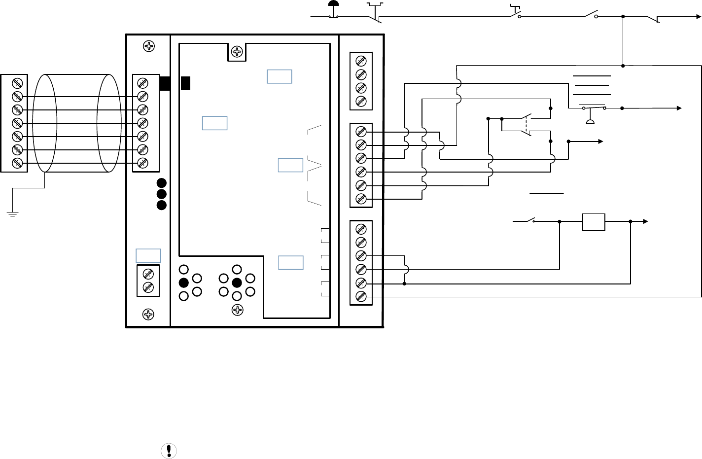
KM1 0 VAC
KM1 Relay
Contact
P
To TM2 Relay
To KM1 Contact
To KM2 Contact
Guidance only; connections may differ with date, model, type, variant, special, custom or concession builds.
This information is intended to be used in conjunction with the compressor’s original control circuit diagram.
+VDC
Load Enable
Load/Unload
VFD/fixed
IN
NO
C
NC
NO
C
NC
RUN
ALARM
READY
OUT
V
SEQ CONT
LOAD UNL
GND
D11
D12
+20V
V
1
2
3
4
5
6
2
1
LED 5 VFD
LED 2 LOAD
LED 1 SEQ
LED 4
READY
LED 3
RUN
C03
C01
C02
C04
C05
IR-PCB
1
2
3
4
5
6
V1
X4I
COMPRESSOR #1
X01 TERMINAL
Refer to the X4I Overview Drawing
for the X4I Compressor 2 through 4
terminal connections
E-STOP
110VAC
HATR
Contact
Restart TD
Relay
Contact
SS
MOL
Contact
SSR UP5 11-22 SD
Excessive Pressure Shutdown Switch Example After Installation
Excessive
Pressure
Shutdown
Switch
Excessive Pressure Shutdown Switch Example After Installation Page 85
