Inkel JF43E1900CFN03 CDMA Fiber-Fed Repeater System User Manual
INKEL Corporation CDMA Fiber-Fed Repeater System
Inkel >
Contents
- 1. Users Manual
- 2. User Manual
User Manual
1. Overview
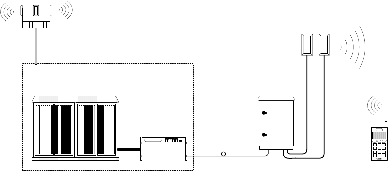
Figure 1. System Configuration
Optic repeater is a type of BTS sub-systems. It is designed to cover the radio-
shadowed areas that could be occurred by obstructions among base stations. The
system provides high quality communication at reasonable cost by adopting high
technologies. For example, the system adopted WDM that multiplexes UL and DL
signals onto a single fiber cable, so that the system can be installed at low cost and
maintained with ease.
2. Major Advantages
A. REMOTE
1) It is easy to install and maintain the system, because it is designed as small size, light
weight, and low power consumption.
2) It is reliable by adopting water and moisture resistant structure.
3) Remote control
Operation, maintenance, and repair is easy by using the system that provides alarm
and information on the Gain Control of Remote Cell, output level control, power on/off,
internal temperature monitoring, and problems concerning optic module. Remote
control can be performed by RF modem so that operation and maintenance personal
can use it easily. And it was designed to operate with comprehensive network
management system.
4) Transmission and Receiving with 1 Core Optic Fiber
It use WDM which enables 2 wave-length (Forward: 1550nm, Reverse: 1510nm) to
Base Station
BTS
Donor
Remote
simultaneously be transmitted and received through 1 Core Optic Fiber
5) Optic AGC (Automatic Gain Control): It is regularly keeping the loss between optic
sections.
6) ALC (Automatic Limit Control): It makes to limit the level of output power less than
the regular level.
B. DONOR
1) It is easy to install and maintain the system, because it is designed as small size, light
weight, and low power consumption.
2) Donor shelf is designed to mount into 19” shelf and also, can be mounted into the
enclosure that is following the IP65 standard.
3) Control
Operation, maintenance, and repair is easy by using the system that provides alarm
and information on the Gain Control of Donor Unit, output level control and problems
concerning optic module. Remote control can be performed by RF modem so that
operation and maintenance personal can use it easily. And it was designed to operate
with comprehensive network management system.
4) Transmission and Receiving with 1 Core Optic Fiber
It use WDM which enables 2 wave-length(Forward:1550nm, Reverse:1510nm) to
simultaneously be transmitted and received through 1 Core Optic Fiber
5) Optic AGC(Automatic Gain Control) : It is regularly keeping the loss between optic
sections.
3. The name and function of each module
A. REMOTE
BATTERYOPTIC UL_1 DL/UL_0 AC_OUTAC_IN
BATTERY
OPTIC
UL_1 DL/UL_0 AC_IN
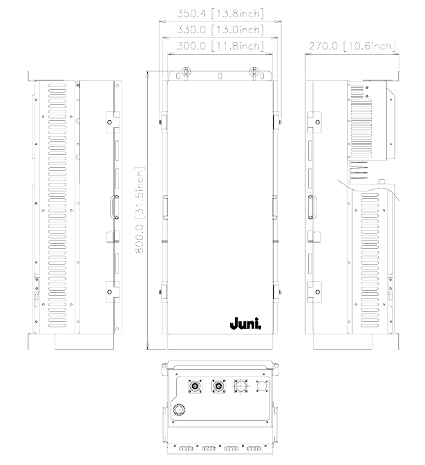
Figure 2. A plan of Remote
3.1 Interior Module
① Optic
It changes the optic signal (from Donor) into RF signal and RF signal (from Remote)
into optic signal.
② DL_UL Drive
The module changes the level of a signal on DL path into the desired level. It has a
variable attenuator. The antenna output level on DL path is adjustable by the attenuator.
It amplifies the level of a signal on UL0 path.
It amplifies the level of a signal on UL1 path after down-conversion.
③ UL_SAW Drive
It contains saw filters for band selection.
④ Local & Modem Drive
It generates local signals for band selection on UL paths.
It performs FSK modulation and demodulation for communication between Donor
and Remote.
⑤ LPA (30Watts)
It is amplified into high output power for transmitting the Down Link signal to
antenna.
⑥ LNA
It amplifies signals from antenna for achieving good characteristics of noise figure.
⑦ Cavity filter
It deletes useless signals except band that is used for service. DL/UL signals are
already distinguished at part of Antenna.
Regarding Up Link Path, It deletes signals except band that is used for service.
⑧ PSU
It changes the input power (50~88VAC) into DC+27V, DC+15V and DC+7V for
operating each module.
⑨ RSM (Remote Status Monitoring)
It manages the communication of Donor and controls alarm signal and all sorts of
control.
3.2 Other parts
① RF Connector : 7/16 DIN Female
② Power Cable : Power Feeder 625 JCAT 3R Coaxial Cable
③ Optic Adapter : Sam-Hwa KFBG #16 (Waterproof, UL certified, the quality of the
material SUS)-using SUNFLEX pipe
④ Bracket : The bracket is used for mounting the repeater on the wall.
B. DONOR
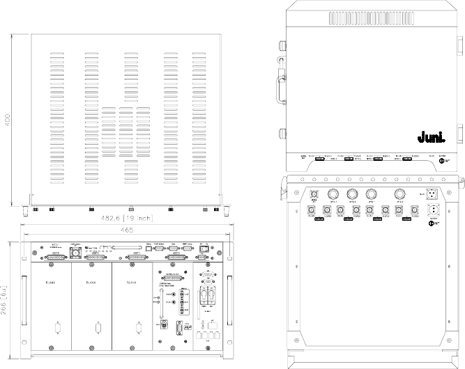
- Donor Shelf - - Donor Enclosure –
3.3 Interior Module
① optic
It changes the optic signal (from Remote) into RF signal and RF signal (from Donor)
into optic signal.
② DL Drive
This module changes the forward signal into optimum level and has attenuation for
setting the input level of optic module. It contains saw filters for band selection.
It contains FSK modem for communication with remote.
③ UL Drive
It amplifies the output signal of optic module for getting optimum level. There is a
function of attenuator for module gain control and setting the gain between optic
sections regularly.
④ Local Drive
This module makes local signal for Reverse diversity path.
It up-converts of UL1 path.
It generates local signals for band selection on DL paths.
⑤ Wireless Modem & control board
They make the signal for communicating the upper systems. The communication is
for receiving and sending the alarm and control signals. Also, the data including the
information of product is communicating with MCU.
⑥ PSU
It changes the input power (110~230VAC) into DC+27V, DC+15, and DC+7V for
operating each module.
⑦ MCU
It has a computer interface. The operator can monitor several kinds of alarms and
control the system by using the connected computer.
3.4 Other parts
① RF connector: N female (Donor enclosure), SMA female (Donor shelf)
② Optic adapter: FC/ APC type
③ Bracket (Enclosure): The bracket is used for mounting the repeater on the wall.
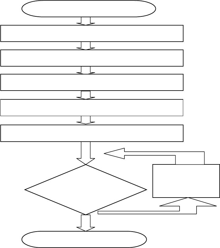
4. How to install the system
Typical Installation Instructions
A. Checking the contents
B. Put the repeater at the place where to install it
C. Install Repeater inside at convenient location on a wall
D. Installation exterior antenna & Laying Feeding cables
E. Measurement of receiving level from base station
i. Connect feeding cable, which has been connected with directional
antenna for base station, with input of spectrum analyzer.
ii. Set measurement environment of Frequency, Span, BW and Amplitude,
etc of the spectrum analyzer.
Install Repeater inside at convenient location on a wall
Fix repeater body on a wall
Installation exterior antenna & Laying Feeding
Completion
Testing
for calling quality
Inspection
Checking the contents
Measurement of Receiving Level from Base Station
Connect power supply adapter

iii. Verify Channel Power value of input signal.
F. Connect to RF Cable
G. Connect power supply adapter
Caution: Should check the input power whether 50~88VAC.(For Remote)
Caution: Should check the input power whether 110~230VAC.(For Donor)
H. Testing for calling qualities
5. User Attention
1) Do not open the case of repeater
2) Do not excessive pressure to Repeater.
3) Please use a rated voltage.
4) The repeater must have been installed considering environmental factor.
6. Troubleshooting
1) The PSU LED
Causes Action
Power cable of the power supply unit
has not been connected. Check connection of power system
Failure of the LED Checking the items of alarm LED
2) The repeater transmits no signal
Causes Action
Coaxial cable connecting the repeater
and measuring system is defective
Replace coaxial cable or power detector
module
Power system of interior of the
repeater has not been connected.
Check power connection of module of
interior of the repeater

7. Specifications
7.1 General System Electrical Specifications
Characteristic Specification
Frequency
DL: 1930.625 ~ 1989.375MHz
UL: 1850.625 ~ 1909.375MHz
Frequency bandwidth 58.75 MHz (DL/UL)
Channel bandwidth and spacing Applying to CDMA Frequency Assignment
System time delay 5 ㎲_max
Characteristic impedance 50 ohm
7.2 DL Path specifications(Remote)
Remote Donor
Input power range -34 ~ -24dBm/total -3 ~ +7dBm/Total
Gain 61~77dB -2dB
Gain control step 0.5dB 0.5dB
Maximum output power 43dBm/total +5dBm/Total
Output VSWR 1.5:1 1.5:1
Ripple 3dB max 2dB max
7.3 UL Path specifications
Remote Donor
Input Power -55 dBm max 0dBm max
Gain +55dB -25 ~ 0dB
Input VSWR 1.5:1 0.5dB
OIP3 25dBm max 1.5:1
Ripple 3dB max 25dBm max
7.4 Mechanical Specifications
Remote Donor
Output/Input connector 7/16 DIN Female N Female
Input AC power 50~88VAC 110~230VAC
Dimensions (W*H*D) 13.8*31.5*10.6(inch) 482.6*266*400(mm)
Weight 79lbs Max 36lbs max
WARNING
Any changes or modifications not expressly approved by the manufacturer could void
the user’s authority to operate the equipment.