Inkel JF43E1900CFN03 CDMA Fiber-Fed Repeater System User Manual
INKEL Corporation CDMA Fiber-Fed Repeater System Users Manual
UserManual.wiki
>
Inkel
>
JF43E1900CFN03 User Manual
>
Users Manual
Contents
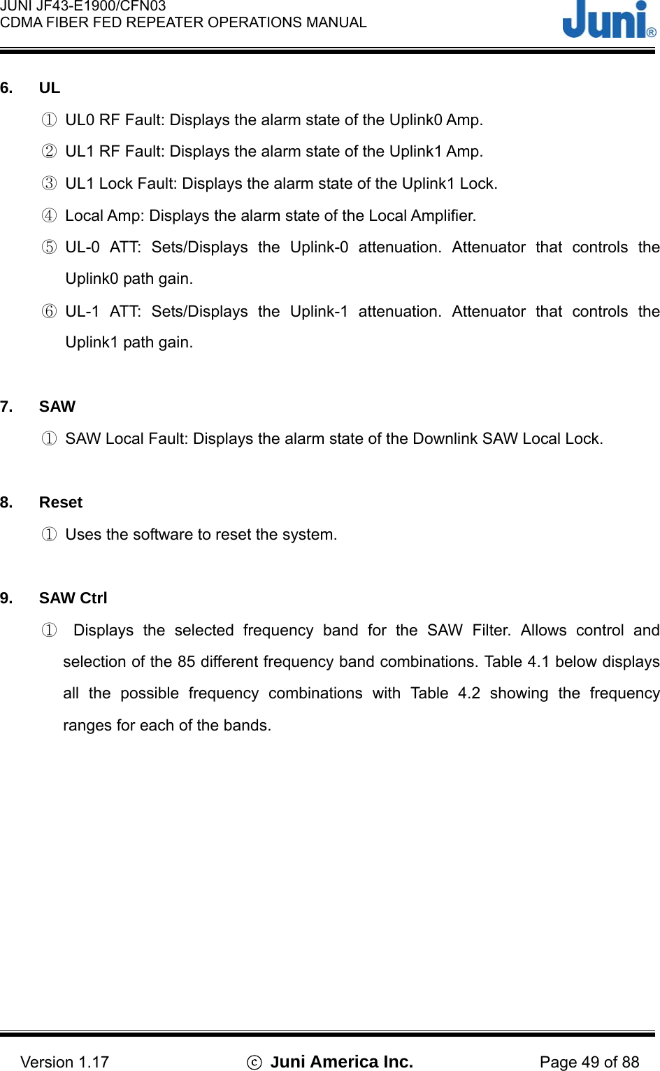
1.
Users Manual
2.
User Manual
Users Manual
Navigation menu
Upload a User Manual
Namespaces
Wiki Guide
HTML
PDF
Info
Views
User Manual
Discussion / Help
Navigation
![JUNI JF43-E1900/CFN03 CDMA FIBER FED REPEATER OPERATIONS MANUAL Version 1.17 ⓒ Juni America Inc. Page 7 of 88 1. Introduction 1.1 Fiber Fed Repeater The JF43 FFR provides a cost effective solution for cell extension coverage and increased call quality in shadow areas. It is a RF signal transport system that provides long range RF coverage where it is impractical to install a BTS. The JF43 FFR is designed to be strategically placed to overcome difficult zoning issues by allowing the base stations to remain at a central location while placing antennas at remote locations. RF signals can be transported to remote locations to expand coverage into areas not receiving service or to extend coverage into difficult to reach areas such as canyons, tunnels and underground parking lots and roadways. The JF43 FFR provides a high-tech, highly-efficient service system which enables high quality communication at low cost, due to the system’s utilization of one optical fiber core between the DHU and RU supporting full duplex transmission of signals for both the DL and UL. Base StationBTSDonorRemoteDL/UL_0Ant.UL_1Ant.Optic Link [Figure 1.1] System Configuration](https://usermanual.wiki/Inkel/JF43E1900CFN03.Users-Manual/User-Guide-597467-Page-7.png)
![JUNI JF43-E1900/CFN03 CDMA FIBER FED REPEATER OPERATIONS MANUAL Version 1.17 ⓒ Juni America Inc. Page 8 of 88 1.2 FFR Components The JF43 FFR system comprises of two main elements, a DHU and RU. [Figure 1.2] Donor Hub Unit Enclosure [Figure 1.3] Remote Unit The DHU Enclosure includes the following: • Donor Optic Module • Donor Rx Module • Donor Tx (SAW, FSK Modem included) Module • Local Module • Control Module • Wireless Modem • Power Supply. The RU includes the following: • Remote Optic Module • Remote T/Rx Module • Remote Rx SAW Module • Control Module • LPA • LNA • Cavity BPF • Power Supply](https://usermanual.wiki/Inkel/JF43E1900CFN03.Users-Manual/User-Guide-597467-Page-8.png)
![JUNI JF43-E1900/CFN03 CDMA FIBER FED REPEATER OPERATIONS MANUAL Version 1.17 ⓒ Juni America Inc. Page 13 of 88 2. System Description 2.1 FFR System The JF43 FFR is made up of a main unit (DHU) and a RU. The DHU and RU are divided into modules to allow easy operation and maintenance. It can operate even in the harshest environmental conditions due to its durable NEMA 4X casing. TX0/RX0TX1/RX1BTSBTS Ant.-30 or -20dBBTS Ant.D/CD/CCable Loss-2~-5dBTX1DuplexerOpticO/E(LD)E/O(PD)RemotePALNALNA BPFBPFOptic AGC-30 or -20dBDuplexerRX1TX1O/E(LD)E/O(PD)AGC(LD,PD)SAWDonor Optic CavityOptic cable15 miles_maxSAWSAWModemModem Ant.Localp-DetT/RX DriveRXAtt.Att.LocalCom.TXRX1OpticCombiner (-10dB)Combiner (-10dB) [Figure 2.1] System Block diagram 2.2 Donor Unit This section describes the main components of the DHU, the functions performed by the components and the user interface.](https://usermanual.wiki/Inkel/JF43E1900CFN03.Users-Manual/User-Guide-597467-Page-13.png)
![JUNI JF43-E1900/CFN03 CDMA FIBER FED REPEATER OPERATIONS MANUAL Version 1.17 ⓒ Juni America Inc. Page 14 of 88 2.2.1 Donor Hub Unit Enclosure and Shelf 123 4 [Figure 2.2] Main Components of the Donor Hub Unit ① FAN: Provides ventilation and disperses heat evenly. ② MCU (Master Control Unit): Monitors and controls each internal module. Also monitors and controls the RU by data communication. Monitoring the control and status of all repeaters can only be managed at an administrative level via the internal SNMP agent. ③ DOC (Donor Optic Cavity): Converts the RF signal (from the BTS) into an optical signal and transmits the signal to the RU. Conversely, the RU converts the optic signal and transmits it to the BTS. ④ PSU (Power Supply Unit): Converts the input power AC power (115 or 230VAC) into DC+27V, DC+15V, DC +7V and supplies the power to the modules.](https://usermanual.wiki/Inkel/JF43E1900CFN03.Users-Manual/User-Guide-597467-Page-14.png)
![JUNI JF43-E1900/CFN03 CDMA FIBER FED REPEATER OPERATIONS MANUAL Version 1.17 ⓒ Juni America Inc. Page 15 of 88 5631 4728 [Figure 2.3] Donor Hub Unit Shelf Interface ① CDMA Modem RF Port (Female N-Type): An RF cable connects the CDMA wireless modem port on the MCU to the modem RF port situated on the outside of the enclosure. ② MCU and SNMP reset Key: Hard reset button to restart the MCU and SNMP agent. ③ Debug port: USB port to allow connection to any PC for debugging via the GUI and LMT. ④ MCU Power switch: Turns the power on/off for the MCU only. ⑤ Main and battery power switch: Main power switch located on the power supply which provides power to the entire DHU. ⑥ Monitoring port (Female SMA): Ports used to monitor signals existing within the DHU with a spectrum analyzer or test equipment. ⑦ RF in/out port: RF ports on a single optic transceiver supports only one sector.](https://usermanual.wiki/Inkel/JF43E1900CFN03.Users-Manual/User-Guide-597467-Page-15.png)
![JUNI JF43-E1900/CFN03 CDMA FIBER FED REPEATER OPERATIONS MANUAL Version 1.17 ⓒ Juni America Inc. Page 16 of 88 This port is connected to the enclosure with RF cables. ⑧ Optic connector: Connector to where the fiber is connected to. ⑨ 12345 [Figure 2.4] Donor Hub Unit External Connectors (Bottom View) ① CDMA modem RF port (Female N-Type): External Antenna modem connected to this port. ② Fiber Entrance: The fiber is passed through to connect to the optic transceiver. ③ AC power connector (Female weatherproof MS type): Connectors used for AC powering. The AC power cable is supplied by the manufacturer. ④ RF in/out port (Female N type): Provides connection to the BTS. ⑤ Battery connector (Female weatherproof MS type): Connector for backup batteries units. : Data and power cable](https://usermanual.wiki/Inkel/JF43E1900CFN03.Users-Manual/User-Guide-597467-Page-16.png)
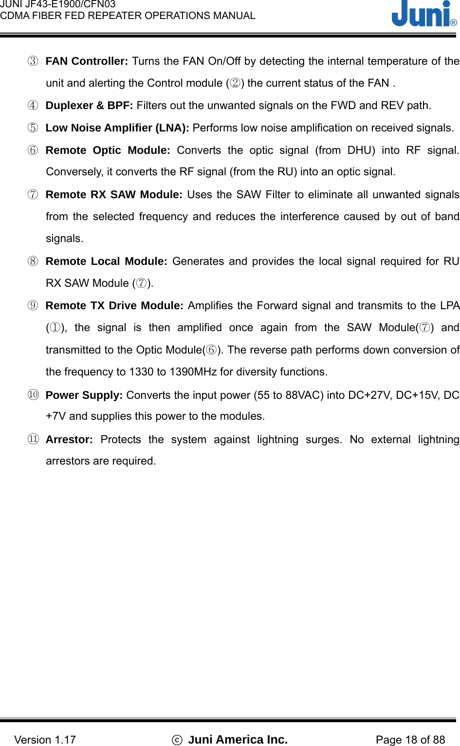
![JUNI JF43-E1900/CFN03 CDMA FIBER FED REPEATER OPERATIONS MANUAL Version 1.17 ⓒ Juni America Inc. Page 17 of 88 2.3 Remote Unit This section describes the main components of the RU, the functions performed by the components and the user interface. 2.3.1 Remote Unit RX IN 260 INNMS 520 OUT NMS220 OUT TX OUT1234567891110 [Figure 2.5] Main Components of the Remote unit ① LPA (Linear Power Amplifier): A 30Watt 6 carrier amplifier which amplifies the signal into high output power for transmitting to the DL antenna. The amplifier is operated by +27VDC and has a 43dB Gain. ② Control Module: Used to monitor and control the RU. Also manages the communication with the DHU.](https://usermanual.wiki/Inkel/JF43E1900CFN03.Users-Manual/User-Guide-597467-Page-17.png)
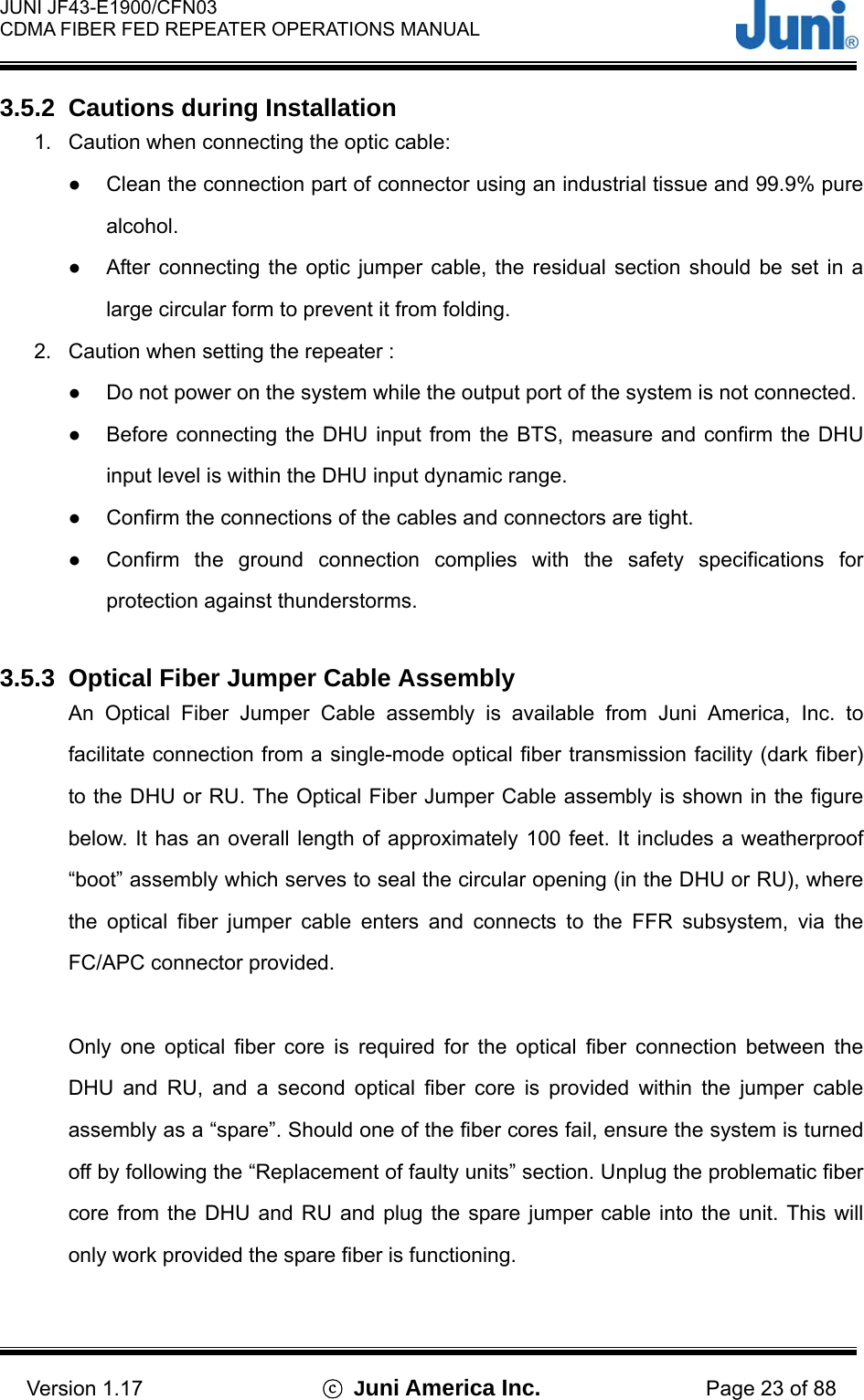
![JUNI JF43-E1900/CFN03 CDMA FIBER FED REPEATER OPERATIONS MANUAL Version 1.17 ⓒ Juni America Inc. Page 19 of 88 2.3.2 Remote Unit Connectors BATTERYOPTICUL_1 DL/UL_0 AC_IN1 2 345 [Figure 2.6] Connectors located on the bottom of the Remote Unit ① Fiber entrance port: A non metallic liquid tight strain relief is connected to the port with a fiber core fed through the center into the RU. ② UL1 path input port: Female DIN type Diversity uplink/receive path port to connect a second antenna ③ DL/UL0 path in/out port: Female DIN type DL/UL path port making use of a single fiber core for full duplex operation. An antenna is connected to this port to transmit and receive signals. ④ Battery connector: Weatherproof 2 pin MS connector used to connect an external battery backup unit. ⑤ AC power connector: Female AC power connector to allow connection for a male Gilbert AC power connector and CATV AC power feeder cable.](https://usermanual.wiki/Inkel/JF43E1900CFN03.Users-Manual/User-Guide-597467-Page-19.png)
![JUNI JF43-E1900/CFN03 CDMA FIBER FED REPEATER OPERATIONS MANUAL Version 1.17 ⓒ Juni America Inc. Page 20 of 88 2.3.3 Remote Dip Switch Settings DIP SWITCH SECTOR DIP SWITCH SECTOR ONOFF12345678 1 ONOFF12345678 3 ONOFF12345678 2 ONOFF12345678 4 [Table 2.1] Dip switch on the Control Unit of the Remote unit The dip switch located on the control unit of the RU is set accordingly to the required sector it must service. A DHU can support a maximum of four remotes which allows the single DHU located at the BTS to service up to four sectors.](https://usermanual.wiki/Inkel/JF43E1900CFN03.Users-Manual/User-Guide-597467-Page-20.png)
![JUNI JF43-E1900/CFN03 CDMA FIBER FED REPEATER OPERATIONS MANUAL Version 1.17 ⓒ Juni America Inc. Page 24 of 88 [Figure 3.1] Optical Fiber Jumper Cable 3.5.4 Weatherproofing Connectors Once all connectors and cables have been configured and assembled, weatherproofing is vital to prevent corrosion due to water ingress which could lead to eventual failure. 1. Making sure that the connector surfaces are clear of residue and dry, firmly tighten the connectors. [Figure 3.2] Connect cable to connector [Figure 3.3] Fasten cable to connector 2. Seal the connector assembly by tightly wrapping Butyl tape over the connection. Two or more layers should be used so that the tape seals the entire connection and extends beyond the connector by about an inch.](https://usermanual.wiki/Inkel/JF43E1900CFN03.Users-Manual/User-Guide-597467-Page-24.png)
![JUNI JF43-E1900/CFN03 CDMA FIBER FED REPEATER OPERATIONS MANUAL Version 1.17 ⓒ Juni America Inc. Page 25 of 88 [Figure 3.4] Wrap connection with Butyl tape 3. Tightly wrap electrical tape around the existing Butyl tape making sure to also extend one inch beyond the Butyl tape to completely envelop the tape and connector. [Figure 3.5] Wrap over Butyl tape with electric tape 3.5.5 Donor Unit Eye Bolts There are four captive eye bolt tapped holes located at the top of the DHU as shown below. The length of the tapped hole is 0.97 inches or 25mm. The customer supplied ¼” 20UNC eye bolts may be used to assist in hoisting the DHU above the ground for wall or pole mount solutions. Ensure that the eyebolts are securely attached to the top of the DHU. Check that the cables used to lift the DHU is securely fastened to the eyebolts before it is lifted.](https://usermanual.wiki/Inkel/JF43E1900CFN03.Users-Manual/User-Guide-597467-Page-25.png)
![JUNI JF43-E1900/CFN03 CDMA FIBER FED REPEATER OPERATIONS MANUAL Version 1.17 ⓒ Juni America Inc. Page 26 of 88 [Figure 3.6] Donor Unit Eye Bolt Patterns 3.5.6 Donor Unit Standard Wall Mount Guide The DHU is capable of being wall mounted. There are two horizontal panels protruding slightly behind the DHU, with holes along the panel to allow bolts and nuts to be fastened. The wall mount holes will accommodate bolt diameters up to a maximum of 0.4 inches. Drill holes in the wall or area in which it is to be installed to match the mounting holes on the panels. Attach the DHU to the wall using the appropriate fastening method. The figure below displays the positioning and size of the wall mount holes.](https://usermanual.wiki/Inkel/JF43E1900CFN03.Users-Manual/User-Guide-597467-Page-26.png)
![JUNI JF43-E1900/CFN03 CDMA FIBER FED REPEATER OPERATIONS MANUAL Version 1.17 ⓒ Juni America Inc. Page 27 of 88 [Figure 3.7] Donor Hub Unit Wall Mounting 3.5.7 Donor Hub Unit Commissioning and Provisioning 1. Verify that the power is switched OFF. 2. Before any other connections are made, ensure that the ground terminal on the DHU cabinet has been connected to the common ground of the installation site, as described in the previous section. 3. Using a DC voltmeter, verify that the DC voltage level at the power terminals is a nominal ±24 VDC. The DC power provided to the Donor can be either polarity. 4. Connect a customer-supplied power cable to the DHU Enclosure. 5. Connect a customer-supplied AC power cable to the front of the DHU power supply when the DHU enclosure is not used. 6. Connect a customer-supplied Optical Fiber cable to the Optic port of the DHU, inside the Enclosure. 7. Connect a customer supplied modem antenna to the RF modem port on the bottom of the DHU unit. 8. Turn the power on with the main switch located on the PSU and then power on the](https://usermanual.wiki/Inkel/JF43E1900CFN03.Users-Manual/User-Guide-597467-Page-27.png)
![JUNI JF43-E1900/CFN03 CDMA FIBER FED REPEATER OPERATIONS MANUAL Version 1.17 ⓒ Juni America Inc. Page 28 of 88 MCU. 9. Connect a PC to the MCU’s debug port with a USB cable. Load the LMT (Local Maintenance Terminal) software to check the status and settings of the DHU. [Figure 3.8] Front View Cable connections on the Donor Hub Unit [Figure 3.9] Cable connections on the Donor Hub Unit Fiber Optic Output DL1/UL1 RF Input from BTS DL0/UL0 RF input from BTS AC Input (55-88VAC) Modem Antenna Connection Fiber Optic Cable Passed Through DL1/UL1 RF Port from BTS DL0/UL0 RF Port from BTS AC Input (55-88VAC) Modem Antenna Connection AC Input (55-88VAC) AC Input (55-88VAC)](https://usermanual.wiki/Inkel/JF43E1900CFN03.Users-Manual/User-Guide-597467-Page-28.png)
![JUNI JF43-E1900/CFN03 CDMA FIBER FED REPEATER OPERATIONS MANUAL Version 1.17 ⓒ Juni America Inc. Page 29 of 88 3.5.8 Remote Unit Eye Bolts There are two captive eye bolt tapped holes located at the top of the RU which is located next to the fan compartment. The length of the tapped hole is 0.7 inches or 18mm. The customer supplied ¼” 20UNC eye bolts may be used to assist in hoisting the RU above the ground for wall or pole mount solutions. Prior to using the eyebolts, ensure that the three eyebolts are securely attached to the top of the RU. Check that the cables used to lift the DHU is securely fastened to the eyebolts before it is lifted. [Figure 3.10] Remote Unit Eye Bolt Patterns 3.5.9 Remote Unit Standard Wall Mount Guide The RU is capable of being wall mounted. There are two horizontal panels extending from the body of the RU at the top and bottom with holes along the panel to allow bolts and nuts to be fastened. The wall mount holes will accommodate bolt diameters up to a maximum of 0.39 inches. Drill holes in the wall or area in which it is to be installed, to match the mounting holes on the panels.](https://usermanual.wiki/Inkel/JF43E1900CFN03.Users-Manual/User-Guide-597467-Page-29.png)
![JUNI JF43-E1900/CFN03 CDMA FIBER FED REPEATER OPERATIONS MANUAL Version 1.17 ⓒ Juni America Inc. Page 30 of 88 Attach the RU to the wall using the appropriate fastening method. The figure below displays the positioning and size of the wall mount holes. DL/UL_0OPTICUL_1 AC_INBATTERYBATTERYOPTIC UL_1 DL/ UL_0 AC_OUTAC_IN [Figure 3.11] Remote Unit Wall Mounting](https://usermanual.wiki/Inkel/JF43E1900CFN03.Users-Manual/User-Guide-597467-Page-30.png)
![JUNI JF43-E1900/CFN03 CDMA FIBER FED REPEATER OPERATIONS MANUAL Version 1.17 ⓒ Juni America Inc. Page 31 of 88 3.5.10 LVAC Cables and Connectors Installation Guide Please refer to Appendix C which contains the cable assembly installation guide from Corning Gilbert on how to prepare and connect the cables and connectors required for the JF-43. 3.5.11 Remote Unit External Powering Configuration (Optional) APC FRP Power Supply(Bottom View) 60V output20A High magnetic circuit breakerInput AC power 115VAC nominal115VAC wiringConnect GroundCable HereConnect GroundCable HereGilbert GRS-625-PF -CH-067-TMale ConnectorCommscope PF625JCAT Power Feeder Coax cableGilbert GRS-625-PF-CH-122-TMale ConnectorRemote Unit Bottom View [Figure 3.12] Remote Unit External Powering Configuration](https://usermanual.wiki/Inkel/JF43E1900CFN03.Users-Manual/User-Guide-597467-Page-31.png)
![JUNI JF43-E1900/CFN03 CDMA FIBER FED REPEATER OPERATIONS MANUAL Version 1.17 ⓒ Juni America Inc. Page 32 of 88 The following procedure is only used when electric power at the site differs to the RU power supply range and results in an external power supply being used. Please follow the procedure below to safely install an external power supply to the RU. 1. Unlock the FRPS enclosure. Let the lid slide down and then pull out at the top. The lid will remain attached to the Power Supply. 2. Check the line power switch of the power supply to ensure that it is OFF. 3. Install a Gilbert male type AC connector into the chassis connector located on the bottom of the Power Supply. 4. Attach the yellow wire with the clamp to the stinger of the male connector. Tighten the setscrew on the lug clamp as shown below. [Figure 3.13] Steps 3 and 4 5. Place #6 copper ground wire into the ground lug located on the bottom of the cabinet. [Figure 3.14] Step 5 6. Route and attach the ground wire according to local electrical codes. 7. Install an approved 20 amp high magnetic circuit breaker on the input power side of the power supply. 8. Install a conduit into the opening on the bottom and attach line power in accordance with local electrical codes. The barrier strip is wired with the hot leg at the top. The bottom connector is chassis ground. Male Gilbert AC connector Yellow wire with clamp Chassis connector](https://usermanual.wiki/Inkel/JF43E1900CFN03.Users-Manual/User-Guide-597467-Page-32.png)
![JUNI JF43-E1900/CFN03 CDMA FIBER FED REPEATER OPERATIONS MANUAL Version 1.17 ⓒ Juni America Inc. Page 34 of 88 [Figure 3.15] Cable connections for the remote unit (Top View) Fiber Optic CablePassed Through UL_1 RF Port DL/UL_0 RF Port AC Input (50 - 88VAC) Battery Cable](https://usermanual.wiki/Inkel/JF43E1900CFN03.Users-Manual/User-Guide-597467-Page-34.png)
![JUNI JF43-E1900/CFN03 CDMA FIBER FED REPEATER OPERATIONS MANUAL Version 1.17 ⓒ Juni America Inc. Page 35 of 88 [Figure 3.16] Cable connections for the remote unit (Bottom View) 3.5.13 Operations Tests This section provides test procedures for the uplink and downlink required to be undertaken in order to set up the JF-43 for optimal service. 3.5.13.1 Optic Cable Loss Test Connect the system as shown below: Fiber Optic (1550nm)DL1/UL1F Inputfrom BTS DL0/UL0 inputfrom BTS Optic Power Meter Fiber Optic CablePassed Through UL_1 RF Port DL/UL_0 RF Port AC Input (55 - 88VAC) Battery Cable AC Input (55 - 88VAC) AC Input (55 - 88VAC)](https://usermanual.wiki/Inkel/JF43E1900CFN03.Users-Manual/User-Guide-597467-Page-35.png)
![JUNI JF43-E1900/CFN03 CDMA FIBER FED REPEATER OPERATIONS MANUAL Version 1.17 ⓒ Juni America Inc. Page 36 of 88 [Figure 3.17] Connection to perform optic cable loss test Check optic cable loss by using an optic power meter or reflectometer 1. With the DHU on, connect the power meter to the optic module of the RU and measure the Forward (1550nm) output level. If the optic input level exceeds +6dBm, check the DHU optic module. 2. If the optic loss is larger than –6dBo (on the basis of 1510nm, optic loss = donor output optic power – remote input optic power) through calculating with measured optic power and if the optic cable length between the DHU and RU is less than 15 miles, check if there is a fault in the PD (Photo Diode) or check the optic cable. 3. If a PD fault has occurred inspect the optic input level and check the optic line. Clean the optic connector and if a fault is still existent, send the repeater back to Juni for repair. * Reference a. Optic cable loss is 0.25dB/km at 1510nm, and connection loss is 0.4dB/connector. The total optic deviation of connector is about 1to2dB. (0.4dB ×2 (connector) = about 1dB) b. At the time of delivery, the Gain is set to be about 38dB (Tx), 20dB (Rx) as a default on the basis of optic cable length being 15 miles. 3.5.14 Setup Procedure for DL/UL Path Gain This section provides test procedures for the uplink and downlink required to be undertaken in order to set up the JF-43 for optimal service. 3.5.14.1 Setup for UL Gain 1. Connect the RF signal generator to the ‘DL/UL_0’ port of the RU. 2. Transmit an input signal of -55dBm to the ‘DL/UL_0’ port using the signal generator. 3. Connect spectrum analyzer to ‘DL/UL_0’ port of the DHU. (Span: 5MHz, amplitude offset = cable loss).](https://usermanual.wiki/Inkel/JF43E1900CFN03.Users-Manual/User-Guide-597467-Page-36.png)
![JUNI JF43-E1900/CFN03 CDMA FIBER FED REPEATER OPERATIONS MANUAL Version 1.17 ⓒ Juni America Inc. Page 37 of 88 4. Adjust the UL0 Main ATT from the LMT (RF power level with measuring spectrum analyzer) to adjust the reverse output to be -35dBm. (This is to set the reverse gain of the system to 0dB considering the 20dB coupler used to connect to the BTS input.) [Figure 3.18] Connection to set up UL gain 3.5.14.2 Setup for DL Gain 1. Check whether the DL input to the DHU is within -3dBm to +7dBm/Total. 2. Set the RU FWD ATT to 25dB. 3. Turn ON the forward LPA. 4. While monitoring the forward output power measurement function of the LMT (Local Maintenance Terminal), adjust the RU forward attenuation to obtain the desired RU forward output level. Note: The technician responsible for the repeater provisioning should have data for off peak and peak hour traffic for the BTS. It is recommended to set the RU output around 7 to 8dB less than the max output (43dBm) at off peak hours (No traffic) to prevent any over power shutdown. DL/UL_0DL0/UL0Donor 6dBoLossSignal GeneratorSpectrum Analyzer Remote](https://usermanual.wiki/Inkel/JF43E1900CFN03.Users-Manual/User-Guide-597467-Page-37.png)
![JUNI JF43-E1900/CFN03 CDMA FIBER FED REPEATER OPERATIONS MANUAL Version 1.17 ⓒ Juni America Inc. Page 38 of 88 [Figure 3.19] Connection to set up DL gain 3.5.14.3 Caution Items ● When adjusting the forward gain, start from the minimum gain setting. ● Max. Output Power should not exceed 20W (about +43dBm), ● When adjusting output levels while monitoring the CDMA test equipments, input the appropriate offset level in the Spectrum Analyzer considering the Cable Loss. (offset value = coupling value + measured cable loss) DL/UL_0DL1/UL1 from BTS Donor 6dBoLossSpectrum Analyzer Remote DL0/UL0 from BTS Spectrum Analyzer](https://usermanual.wiki/Inkel/JF43E1900CFN03.Users-Manual/User-Guide-597467-Page-38.png)
![JUNI JF43-E1900/CFN03 CDMA FIBER FED REPEATER OPERATIONS MANUAL Version 1.17 ⓒ Juni America Inc. Page 42 of 88 [Figure 4.1] LMT Start up Screen - 1 If a connection is made between the repeater and the software running computer, it will display the screen shown below. 1. Pause communication with Repeater 2. Displays installed Repeaters 3. Communication status with Repeater 4. Status](https://usermanual.wiki/Inkel/JF43E1900CFN03.Users-Manual/User-Guide-597467-Page-42.png)
![JUNI JF43-E1900/CFN03 CDMA FIBER FED REPEATER OPERATIONS MANUAL Version 1.17 ⓒ Juni America Inc. Page 43 of 88 [Figure 4.2] LMT Start up Screen - 2 1) Pause communication with Repeater: This button is used for momentarily disabling and re-enabling communication with the Repeater. Communication with the Repeater is automatically disabled during program startup and Repeater Firmware downloads. When the communication is paused, the icon will be displayed as below, and the LED’s on the bottom of the screen will pause its flashing. [Figure 4.3] Pause Icon 2) Installed Repeaters Display: Displays the Repeaters installed as a hierarchical tree. Information for the items in this tree may be viewed by either double clicking on the content or right-clicking on the mouse and selecting “Status & Control” menu as 1. Pause communication with Repeater 2. Displays installed Repeaters 3. Communication status with Repeater 4. Status](https://usermanual.wiki/Inkel/JF43E1900CFN03.Users-Manual/User-Guide-597467-Page-43.png)
![JUNI JF43-E1900/CFN03 CDMA FIBER FED REPEATER OPERATIONS MANUAL Version 1.17 ⓒ Juni America Inc. Page 44 of 88 illustrated below. [Figure 4.4] Status & Control 3) Communication status with Repeater: The Progress Bar and LED's display the status of communication with the Repeater at the bottom of the screen. 4) Status: Displays “Disconnect” when there is no communication and “Connect” when there is communication between the repeater and the LMT program. 4.2.3 Communication Settings When the repeater is connected to the computer via USB cable for the first time, it will automatically detect the hardware and run the new hardware wizard. Install the manufacturer supplied driver to enable communication between the repeater and the computer. 4.2.4 Repeater Setup To configure the repeater settings, click the “Option” menu and select the “Repeater Setup” as shown in Figure 4.5. This will bring up the “Repeater Set up” window as shown in Figure 4.6 below. [Figure 4.5] Choosing Repeater Setup](https://usermanual.wiki/Inkel/JF43E1900CFN03.Users-Manual/User-Guide-597467-Page-44.png)
![JUNI JF43-E1900/CFN03 CDMA FIBER FED REPEATER OPERATIONS MANUAL Version 1.17 ⓒ Juni America Inc. Page 45 of 88 [Figure 4.6] Repeater Setup Window Click the “Load” button to display the current configuration. To make changes to the current settings, tick the box beside each of the desired items and click “Save” and then “OK”. For initials setting values and instructions, please refer to section 4.2.6.3. 4.2.5 Offset Calibration Since the power level readings can differ to the actual RF power level by up to 1dB, an offset feature exists within the LMT that allows you to calibrate the LMT to synchronize the readings from the RF test equipment. The default offset values for all repeaters are set to 0. To access the offset feature, do as shown in figure 4.4 and select “Offset” to display the window below. The process is the same for both Donor and Remote. [Figure 4.7] Default Offset Feature Window for Remote and Donor To set an offset for a particular parameter, first check the CHG box to enable the LMT](https://usermanual.wiki/Inkel/JF43E1900CFN03.Users-Manual/User-Guide-597467-Page-45.png)
![JUNI JF43-E1900/CFN03 CDMA FIBER FED REPEATER OPERATIONS MANUAL Version 1.17 ⓒ Juni America Inc. Page 46 of 88 to read and save the settings. Entering a value without check the box will have no effect on the repeater. Once the values have been inputted, press ‘Save’ to save the values and ‘Load’ to load the offset values to the unit. When complete, uncheck the marked boxes and close the offset window. [Figure 4.8] Offset Calibration 4.2.6 Repeater Status Monitoring and Control To view the status of installed Repeaters, double click on the desired Repeater in Figure 4.5 to bring up the Control Window. This can also be done by right-clicking on the desired Repeater and selecting the “Status & Control” command as shown in Figure 4.4.](https://usermanual.wiki/Inkel/JF43E1900CFN03.Users-Manual/User-Guide-597467-Page-46.png)
![JUNI JF43-E1900/CFN03 CDMA FIBER FED REPEATER OPERATIONS MANUAL Version 1.17 ⓒ Juni America Inc. Page 47 of 88 [Figure 4.9] Donor Unit Status Window 4.2.6.1 Donor Unit Window The system status may be monitored by the color indicated beside each of the alarm contents. Red color denotes a fault/alarm status whereas the Green denotes normal status. 1. S/W Version Displays the current software version of the Juni_Serial.exe program. 2. Site ID: Displays the location or the site name of where the repeater is installed. By checking the CHG box, the site ID of the DHU can be renamed and saved. 3. Optic ① LD Fault: Displays the alarm state of the Laser Diode. Generates alarm when the](https://usermanual.wiki/Inkel/JF43E1900CFN03.Users-Manual/User-Guide-597467-Page-47.png)
![JUNI JF43-E1900/CFN03 CDMA FIBER FED REPEATER OPERATIONS MANUAL Version 1.17 ⓒ Juni America Inc. Page 50 of 88 [Table 4.1] 85 Possible Frequency Band Combinations Band Frequency A1 1850 to 1855 MHz A2 1855 to 1860 MHz A3 1860 to 1865 MHz D 1865 to 1870 MHz B1 1870 to 1875 MHz B2 1875 to 1880 MHz B3 1880 to 1885 MHz E 1885 to 1890 MHz F 1890 to 1895 MHz C1 1895 to 1900 MHz C2 1900 to 1905 MHz C3 1905 to 1910 MHz [Table 4.2] Frequency band ranges of Table 4 Note: Frequencies C1, C2, C3 are identical to FCC’s C3, C4, and C5. 4.2.6.2 Remote Window normal 5MHz normal 15MHz normal 20MHz 5+15 15+5A1 A A,D A1+A2 D+B2 B3+C1 A1+(A3,D,B1) A+B1A2 A2,A3,D A2,A3,D,B1 A1+A3 D+B3 B3+C2 A2+(D,B1,B2) (A2,A3,D)+B2A3 A3,D,B1 A3,D,B1,B2 A1+D D+E E+F A3+ B (A3,D,B1)+B3D D,B1,B2 D,B A1+B1 B1+B2 E+C1 D+(B2,B3,E) (D,B1,B2)+EB1 B B,E A2+A 3 B1+B3 E+C2 B1+(B3,E,F) B+FB2 B2,B3,E B2,B3,E,F A2+D B1+E E+C3 B2+(E,F,C1) (B2,B3,E)+C1B3 B3,E,F B3,E,F,C1 A2+B1 B1+F F+C1 B3+(F,C1,C2) (B3,E,F)+C2E E,F,C1 E,F,C1,C2 A2+B2 B2+B3 F+C2 E+C (E,F,C1)+C3F F,C1,C2 F,C A3+D B2+E F+C3C1 C A 3+B1 B2+F C1+C2C2 A 3+B2 B2+C1 C1+C3C3 A3+B3 B3+E C2+C3D+B1 B3+F12 10 9 8 8Total Count5+53885](https://usermanual.wiki/Inkel/JF43E1900CFN03.Users-Manual/User-Guide-597467-Page-50.png)
![JUNI JF43-E1900/CFN03 CDMA FIBER FED REPEATER OPERATIONS MANUAL Version 1.17 ⓒ Juni America Inc. Page 51 of 88 To view the Remote-0 status screen displayed in Figure 4.9, right-click on Remote-0 and select “Status & Control” command as illustrated in the Figure 4.8 below. [Figure 4.10] Remote_0 Select [Figure 4.11] Remote_0 Status](https://usermanual.wiki/Inkel/JF43E1900CFN03.Users-Manual/User-Guide-597467-Page-51.png)
![JUNI JF43-E1900/CFN03 CDMA FIBER FED REPEATER OPERATIONS MANUAL Version 1.17 ⓒ Juni America Inc. Page 54 of 88 Remote DL ATT: 10 dB For external attenuator values and internal attenuator settings for DHU BTS power values of +47dBm and +42dBm, please refer to the diagrams in Appendix B. 4.2.7 Repeater Download [Figure 4.12] Select “Download” In order to download a new firmware version to a repeater, right-click the desired repeater and select “Down Load” from the drop down menu as illustrated in Figure 4.10 above. This will generate a new Download window as shown in Figure 4.11 below. [Figure 4.13] Download Window Click “Select File” button to display the Open File window as shown in Figure 4.12 below.](https://usermanual.wiki/Inkel/JF43E1900CFN03.Users-Manual/User-Guide-597467-Page-54.png)
![JUNI JF43-E1900/CFN03 CDMA FIBER FED REPEATER OPERATIONS MANUAL Version 1.17 ⓒ Juni America Inc. Page 55 of 88 [Figure 4.14] Open File Window Locate the desired file to download and click the “Open” button. Then click the “Start” button as illustrated in Figure 4.13 to initiate the download process. The monitoring of the download progress may be viewed via the Download bar displayed on the download window. If the “Stop” button is pressed during the download process, the program returns to the original program installed prior to the download process. [Figure 4.15] File downloading Click the “OK” button at the end of the download as illustrated below in Figure 4.14, to confirm the completion of the download process.](https://usermanual.wiki/Inkel/JF43E1900CFN03.Users-Manual/User-Guide-597467-Page-55.png)
![JUNI JF43-E1900/CFN03 CDMA FIBER FED REPEATER OPERATIONS MANUAL Version 1.17 ⓒ Juni America Inc. Page 56 of 88 [Figure 4.16] Download Complete Confirmation](https://usermanual.wiki/Inkel/JF43E1900CFN03.Users-Manual/User-Guide-597467-Page-56.png)
![JUNI JF43-E1900/CFN03 CDMA FIBER FED REPEATER OPERATIONS MANUAL Version 1.17 ⓒ Juni America Inc. Page 57 of 88 4.3 SNMP Operation 4.3.1 Introduction The DHU utilizes a wireless CDMA modem connected to the SNMP agent to transmit SNMP traps and informs to a central Sprint EMS (Element Management Server) on the Sprint private network. The traps, or commonly referred to as a heartbeat, are sent at an interval of every 20 minutes and it a method of notifying the EMS that the repeater is still connected to the network and is functioning correctly. Informs are transmitted when an alarm at a RU occurs. The inform is sent to the EMS providing information on the type of alarm that has occurred and which repeater it originates from. DURURUMCUHeartbeatSNMP Heartbeats transmitted every 20 minutesWireless modemRemote Units are monitored at the Donor Unit via the fiber link. The SNMP agent located in the MCU generates the heartbeats for transmissionThe wireless modem is registered to Sprint’s private network in order to allow the Donor Unit to transmit heartbeats and alarms to the EMSSNMP alarms transmitted whenever alarms occur with an acknowledgement sent by the EMSAlarmsAlarmsSprint Private NetworkSprint EMSHeartbeat Heartbeat[Figure 4.17] SNMP Operation Overview 4.3.2 Connection Setup for PC to Donor Unit MCU (Master Control Unit) Connect a RS232C cable from the PC directly to the SNMP debug port on the MCU. Open HyperTerminal in Windows and create a new connection. Enter a session name and press OK.](https://usermanual.wiki/Inkel/JF43E1900CFN03.Users-Manual/User-Guide-597467-Page-57.png)
![JUNI JF43-E1900/CFN03 CDMA FIBER FED REPEATER OPERATIONS MANUAL Version 1.17 ⓒ Juni America Inc. Page 58 of 88 [Figure 4.18] HyperTerminal New Connection Choose the COM port to which the MCU is connected on the PC and press OK. In this example the modem is connected to COM port 4. [Figure 4.19] Connection Settings](https://usermanual.wiki/Inkel/JF43E1900CFN03.Users-Manual/User-Guide-597467-Page-58.png)
![JUNI JF43-E1900/CFN03 CDMA FIBER FED REPEATER OPERATIONS MANUAL Version 1.17 ⓒ Juni America Inc. Page 59 of 88 Choose 38400 Bits Per Second and press OK to enable communication with the MCU. [Figure 4.20] Connection Settings The session is created and HyperTerminal is now connected to the DHU MCU. Click on File->Properties and on the window select the settings tab.](https://usermanual.wiki/Inkel/JF43E1900CFN03.Users-Manual/User-Guide-597467-Page-59.png)
![JUNI JF43-E1900/CFN03 CDMA FIBER FED REPEATER OPERATIONS MANUAL Version 1.17 ⓒ Juni America Inc. Page 60 of 88 [Figure 4.21] Connection Settings With the settings tab selected, select ANSIW for the emulation and press OK.](https://usermanual.wiki/Inkel/JF43E1900CFN03.Users-Manual/User-Guide-597467-Page-60.png)
![JUNI JF43-E1900/CFN03 CDMA FIBER FED REPEATER OPERATIONS MANUAL Version 1.17 ⓒ Juni America Inc. Page 61 of 88 [Figure 4.22] Connection Settings The session will now allow characters to be typed into the screen in a human readable format. Type “at” or “AT” into the window and an “OK” response should be displayed. This means a direct connection to the MCU has been established and AT commands can now be entered. [Figure 4.23] Connection Established with Response from Modem](https://usermanual.wiki/Inkel/JF43E1900CFN03.Users-Manual/User-Guide-597467-Page-61.png)
![JUNI JF43-E1900/CFN03 CDMA FIBER FED REPEATER OPERATIONS MANUAL Version 1.17 ⓒ Juni America Inc. Page 62 of 88 The HyperTerminal should now be ready to accept user input from the keyboard. Once the PC is connected to and can access the MCU, it will display a LINUX command shell such as the figure below. [Figure 4.24] MCU Start-up Screen Output If the screen is blank, press the enter key and a tilde pound (to #) command will be displayed. This means that the MCU is ready to accept input. Please refer to the next section to view and alter settings on the MCU. 4.3.3 View and Change SNMP Destination IP To view and change the SNMP destination IP, the PC should be connected to the MCU via a RS232C cable. With the “to #” command displayed, type in “snmptool” to display the following menu. Note: Any changes made other than the ones listed below can prevent the SNMP from functioning properly.](https://usermanual.wiki/Inkel/JF43E1900CFN03.Users-Manual/User-Guide-597467-Page-62.png)
![JUNI JF43-E1900/CFN03 CDMA FIBER FED REPEATER OPERATIONS MANUAL Version 1.17 ⓒ Juni America Inc. Page 63 of 88 [Figure 4.25] SNMP Menu Press 4 and then enter. This will display all the IP addresses to which the traps and informs will be sent. [Figure 4.26] Display Trap Destination To enter another or new trap destination address, press 5 at the menu and enter the new IP, community and port separated by a space such as the figure below. To exit](https://usermanual.wiki/Inkel/JF43E1900CFN03.Users-Manual/User-Guide-597467-Page-63.png)
![JUNI JF43-E1900/CFN03 CDMA FIBER FED REPEATER OPERATIONS MANUAL Version 1.17 ⓒ Juni America Inc. Page 64 of 88 without entering an IP, leave the line blank and enter. [Figure 4.27] Add Trap Destination To delete a destination IP, enter 4 to view all the list of IP’s and the slot number associated with the IP address. Enter 6 to enter deletion mode and enter the desired slot number. Once all necessary changes have been made to the IP, press 7 to save and then 11 to return to the normal command prompt. 4.3.4 Downloading SNMP History Log The FFR DHU supports remote downloading of logs via FTP provided the system has been set up accordingly to the previous sections. Downloading the logs can be done on any computer as long as an internet](https://usermanual.wiki/Inkel/JF43E1900CFN03.Users-Manual/User-Guide-597467-Page-64.png)
![JUNI JF43-E1900/CFN03 CDMA FIBER FED REPEATER OPERATIONS MANUAL Version 1.17 ⓒ Juni America Inc. Page 65 of 88 connection is available. Open “Run” in the windows start menu and type in “ftp <IP>”, where <IP> is the IP address assigned to the DHU. An IP of 210.120.92.242 is used as an example in the figure below. [Figure 4.28] FTP access to Donor Unit The username and password to log onto the FTP is: Username: ftp Password: <blank> (no password required) To download the logs, enter the following commands in the exact given order. > lcd c:\ > cd mp202 > get history_log > get history_snmp_log > quit Figure 4.27 shows the response from the FTP server after each command.](https://usermanual.wiki/Inkel/JF43E1900CFN03.Users-Manual/User-Guide-597467-Page-65.png)
![JUNI JF43-E1900/CFN03 CDMA FIBER FED REPEATER OPERATIONS MANUAL Version 1.17 ⓒ Juni America Inc. Page 66 of 88 [Figure 4.29] FTP Commands 4.3.5 Reading and Understanding the SNMP History Log Once the log has been downloaded locally to a PC, the information below explains what each line of the log means. Sync Time: Sync time setting successful.. (Synchronization of SNMP agent and modem clock) Snmp notification, Check Network successful, 07/18/05 17:05:52 (SNMP agent checks the Network Connection to determine connectivity) Snmp notification, go to AT-NOK mode, 07/18/05 15:54:50 (Notification by SNMP agent that it is now entering Network Online Mode) SEND[1:0] HeartBeat Trap, 07/18/05 16:14:56 (Transmission of first heartbeat (count=0) within one hour timeframe) SEND[1:1] HeartBeat Trap, 07/18/05 16:34:58 (Transmission of second heartbeat (count=1) within one hour timeframe) SEND[1:2] HeartBeat Trap, 07/18/05 16:55:01 (Transmission of third heartbeat (count=2) within one hour timeframe)](https://usermanual.wiki/Inkel/JF43E1900CFN03.Users-Manual/User-Guide-597467-Page-66.png)
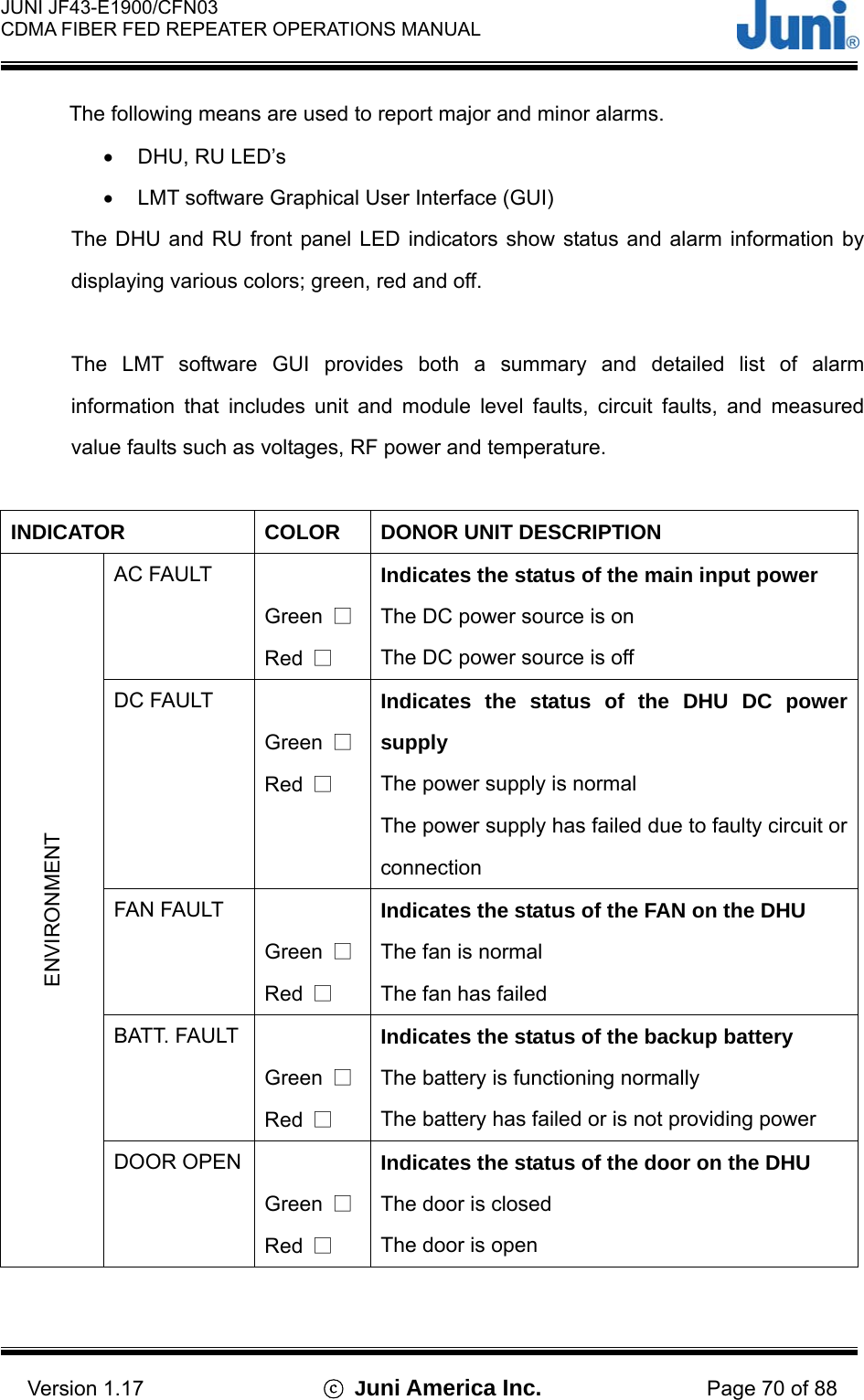
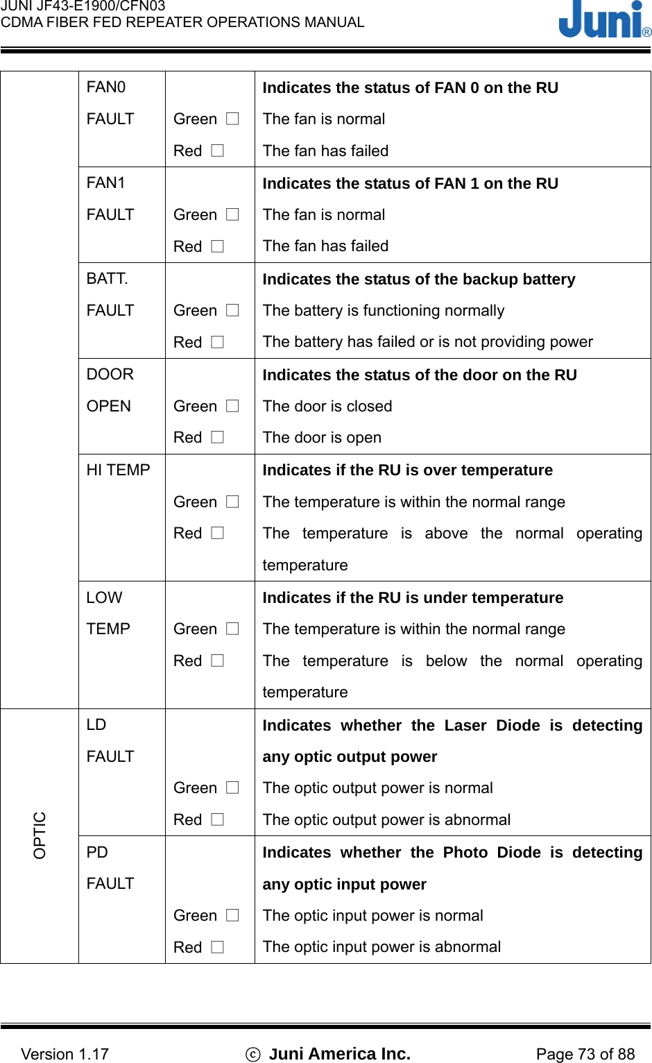
![JUNI JF43-E1900/CFN03 CDMA FIBER FED REPEATER OPERATIONS MANUAL Version 1.17 ⓒ Juni America Inc. Page 72 of 88 UL1 RF FAULT Green □ Red □ Indicates the state of the Uplink1 amplifier The amplifier is functioning normally The amplifier has failed or the RF power output has shutdown UL1 LOCK FAULT Green □ Red □ Indicates the state of the Rx Local Oscillator (in the optic module) The UL1 local oscillator is normal The Rx local oscillator has lost phase lock and may have a frequency error LOCAL AMP Green □ Red □ Indicates the state of the local amplifier The amplifier is functioning normally The amplifier has failed or the RF power output has shutdown SAW SAW LOCAL FAULT Green □ Red □ Indicates the state of the downlink SAW local oscillator The local oscillator is normal The local oscillator (in the SAW Tx module) has lost phase lock and may have a frequency error [Table 5.1] Donor Unit Alarm Items INDICATOR COLOR REMOTE UNIT DESCRIPTION AC FAULT Green □ Red □ Indicates the status of the main input power The DC power source is on The DC power source is off ENVIRONEMNT DC FAULT Green □ Red □ Indicates the status of the RU DC power supply The power supply is normal The power supply has failed due to faulty circuit or connection](https://usermanual.wiki/Inkel/JF43E1900CFN03.Users-Manual/User-Guide-597467-Page-72.png)
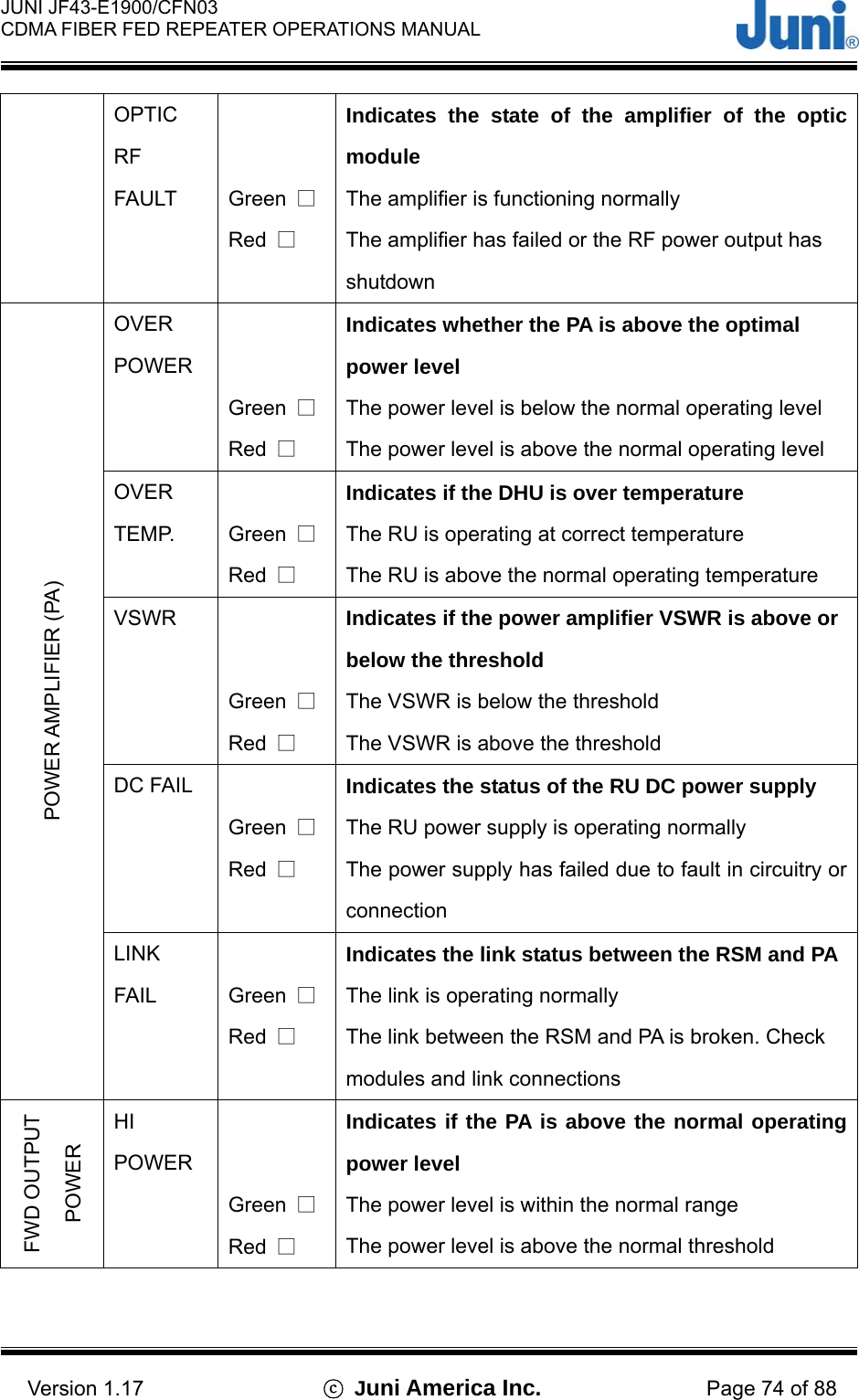
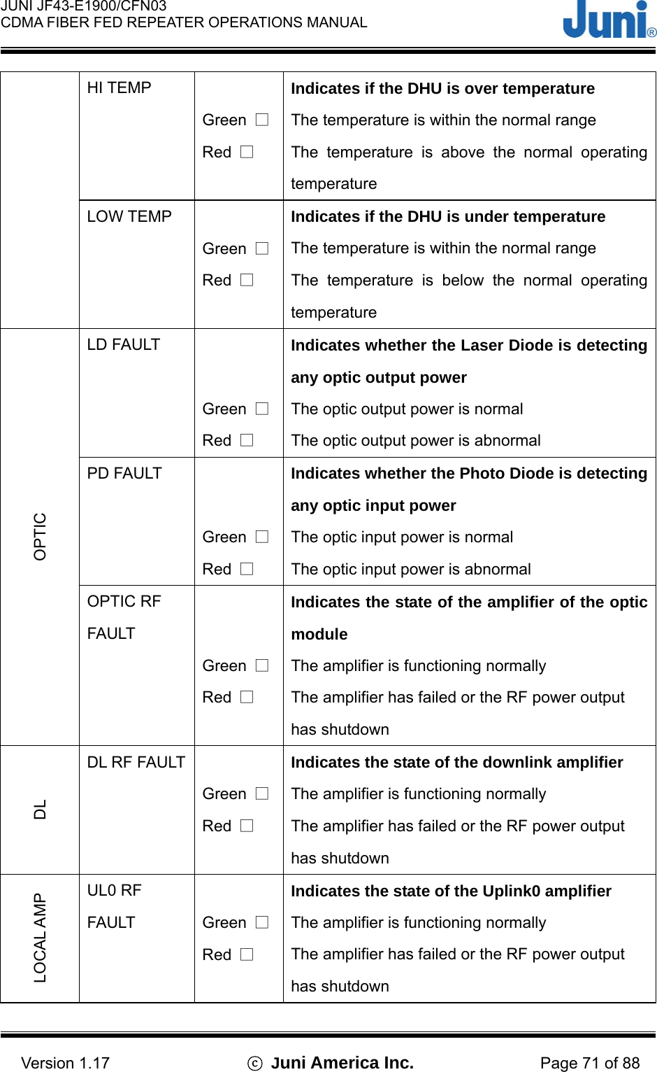
![JUNI JF43-E1900/CFN03 CDMA FIBER FED REPEATER OPERATIONS MANUAL Version 1.17 ⓒ Juni America Inc. Page 75 of 88 LO POWER Green □ Red □ Indicates if the PA is below the normal operating power level The power level is within the normal range The power level is below the normal threshold DL/UL AMP FAULT Green □ Red □ Indicates if the uplink or downlink is normal or has failed The UL/DL amp is normal The UL/DL amp has died or shutdown UL0/1 LNA Green □ Red □ Indicates the status of the UL0 Low Noise Amplifier The UL0/1 LNA is normal The UL0/1 LNA is not functioning correctly. Check the module gain UL0/1 SAW AMP FAULT Green □ Red □ Indicates the status of the UL0/1 SAW amplifier The UL0/1 SAW amp is functioning correctly The UL0/1 SAW amp is not functioning correctly. Check the module gain SAW LOCAL AMP FAULT Green □ Red □ Indicates the status of the local drive amplifier The local amplifier is normal The local amplifier is faulty. Check the frequency of the output signal. RF SAW LOCAL LOCK FAULT Green □ Red □ Indicates the status of the local oscillator The local oscillator is normal The local oscillator (in the SAW module) has lost phase lock and may have a frequency error [Table 5.2] Remote Unit Alarm Items](https://usermanual.wiki/Inkel/JF43E1900CFN03.Users-Manual/User-Guide-597467-Page-75.png)
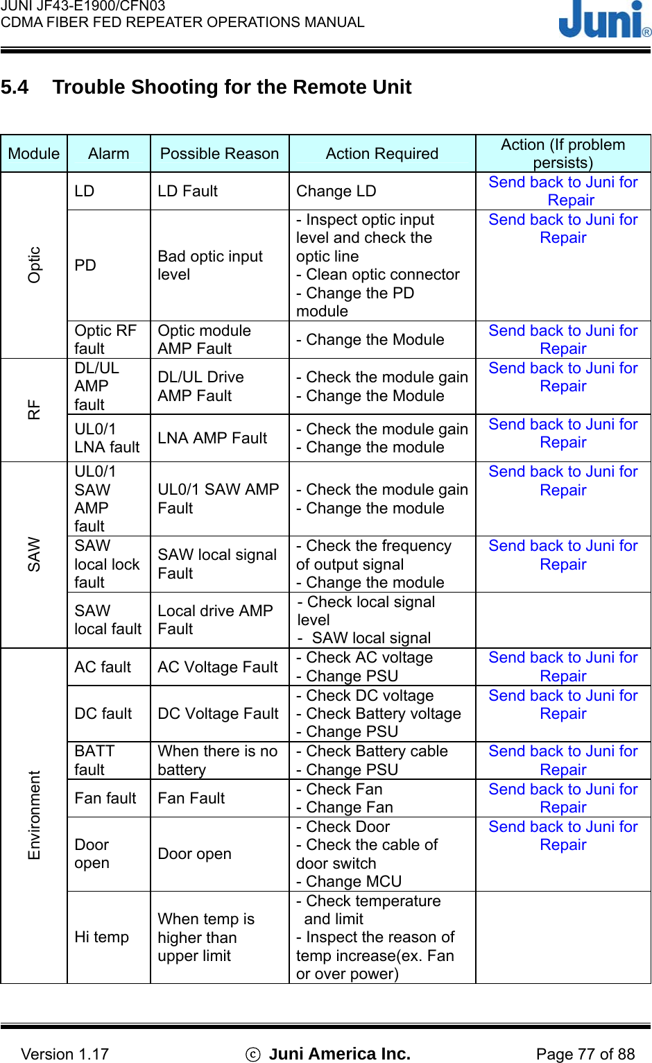
![JUNI JF43-E1900/CFN03 CDMA FIBER FED REPEATER OPERATIONS MANUAL Version 1.17 ⓒ Juni America Inc. Page 76 of 88 5.3 Trouble Shooting for the Donor Unit Module Alarm Possible Reason Action Required Action (If problem persists) LD LD Fault - Change LD Send back to Juni for Repair PD Bad optic input level - Inspect optic input level and check the optic line - Clean optic connector - Change the PD module Send back to Juni for Repair Optic Optic RF fault Optic module AMP Fault Change the Module Send back to Juni for Repair UL0 RF fault UL0 path AMP Fault - Check the module gain - Change the Module Send back to Juni for Repair UL UL1 RF fault UL1 path AMP Fault - Check the module gain - Change the module Send back to Juni for Repair Local AMP UL1 local signal path AMP Fault - Check the Local signal output level - Change the module Send back to Juni for Repair UL1 rock fault UL1 local signal Fault - Check the frequency of output signal - Change the module Send back to Juni for Repair SAW SAW local fault Local drive AMP fault - Check local oscillator signal in the SAW module AC fault AC Voltage Fault - Check AC voltage - Change PSU Send back to Juni for Repair DC fault DC Voltage Fault - Check DC voltage - Check Battery voltage - Change PSU Send back to Juni for Repair BATT fault When there is no battery - Check Battery cable - Change PSU Send back to Juni for Repair Fan fault Fan Fault - Check Fan - Change Fan Send back to Juni for Repair Door open Door open - Check Door - Check the cable of door switch - Change MUC Send back to Juni for Repair Hi temp When temp is higher than upper limit - Check temperature and limit - Inspect the reason of temp increase(ex. Fan or over power) Environment Low tempWhen temp is lower than lower limit - Check temperature and limit - Inspect the reason of temp decrease [Table 5.3] Donor Unit Trouble Shooting Guide](https://usermanual.wiki/Inkel/JF43E1900CFN03.Users-Manual/User-Guide-597467-Page-76.png)
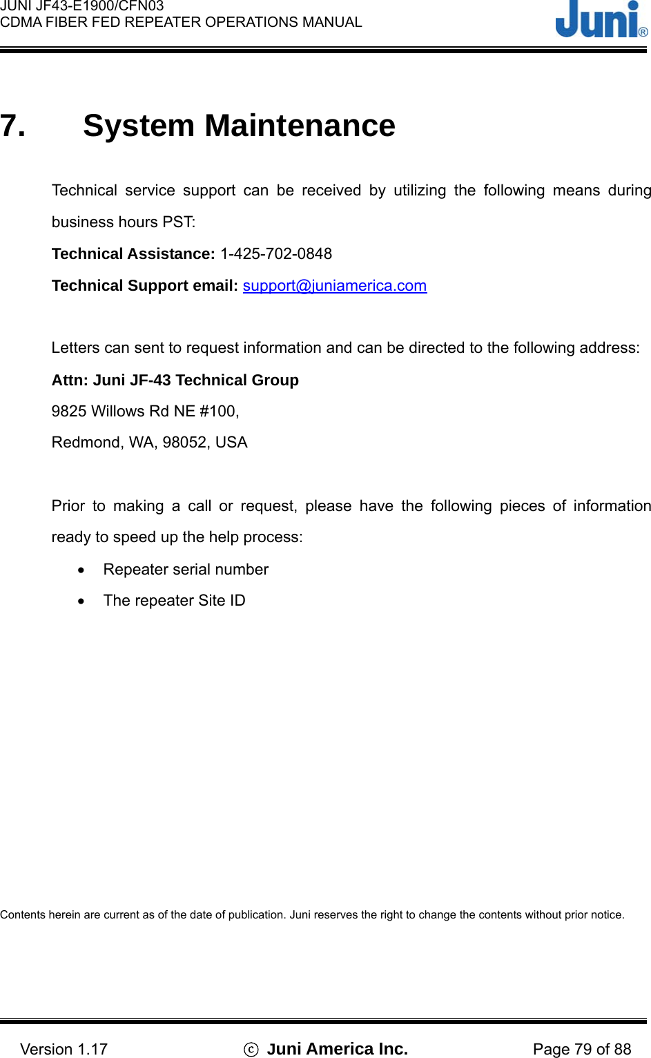
![JUNI JF43-E1900/CFN03 CDMA FIBER FED REPEATER OPERATIONS MANUAL Version 1.17 ⓒ Juni America Inc. Page 78 of 88 Low temp When temp is lower than lower limit - Check temperature and limit - Inspect the reason of temp decrease Over Power Alarm: >46dBm±0.5dB Shutdown: >47dBm±0.5dB - Check input level - Check output level Over Temp Alarm: 80to85°C Shutdown: >85°C Auto recovery: <75°C - Check temp - Check Fan - Check LPA output power level VSWR Alarm: <10dB (return loss) Shutdown: <6dB (@output power 30to47dBm) - Check cables after LPA - Check duplex filter - Check antenna - Change LPA Send back to Juni for repair if problem continues DC Fail ≤ 19.5V DC or ≥ 30.5V DC - Check DC power Link Fail No communication with RSM - Check Data Cable - Check connector PA PA on/off @LPA power off - Change LPA Send back to Juni for Repair Hi Power When output power is higher than upper limit - Check output power level - Check setting limit Forward Output Power Lo Power When output power is lower than lower limit - Check output power level - Check setting limit [Table 5.4] Remote Unit Trouble Shooting Guide](https://usermanual.wiki/Inkel/JF43E1900CFN03.Users-Manual/User-Guide-597467-Page-78.png)
![JUNI JF43-E1900/CFN03 CDMA FIBER FED REPEATER OPERATIONS MANUAL Version 1.17 ⓒ Juni America Inc. Page 80 of 88 Appendix A. JF-43 Mechanics 1. Donor Unit [Figure A1.1] Donor Unit](https://usermanual.wiki/Inkel/JF43E1900CFN03.Users-Manual/User-Guide-597467-Page-80.png)
![JUNI JF43-E1900/CFN03 CDMA FIBER FED REPEATER OPERATIONS MANUAL Version 1.17 ⓒ Juni America Inc. Page 81 of 88 [Figure A1.2] Donor Unit Wall Mounting](https://usermanual.wiki/Inkel/JF43E1900CFN03.Users-Manual/User-Guide-597467-Page-81.png)
![JUNI JF43-E1900/CFN03 CDMA FIBER FED REPEATER OPERATIONS MANUAL Version 1.17 ⓒ Juni America Inc. Page 82 of 88 [Figure A1.3] Donor Unit Front View](https://usermanual.wiki/Inkel/JF43E1900CFN03.Users-Manual/User-Guide-597467-Page-82.png)
![JUNI JF43-E1900/CFN03 CDMA FIBER FED REPEATER OPERATIONS MANUAL Version 1.17 ⓒ Juni America Inc. Page 83 of 88 2. Remote Unit [Figure A2.1] Remote Dimensions OPTICBATTERYUL_1 AC_INDL/UL_0AC_INUL_1BATTERYOPTIC DL/UL_0 AC_OUTRemote Unit(20W)FAN UNIT](https://usermanual.wiki/Inkel/JF43E1900CFN03.Users-Manual/User-Guide-597467-Page-83.png)
![JUNI JF43-E1900/CFN03 CDMA FIBER FED REPEATER OPERATIONS MANUAL Version 1.17 ⓒ Juni America Inc. Page 84 of 88 DL/UL_0OPTICUL_1 AC_INBATTERYBATTERYOPTIC UL_1 DL/UL_0 AC_OUTAC_IN [Figure A2.2] Remote Unit Wall Mounting](https://usermanual.wiki/Inkel/JF43E1900CFN03.Users-Manual/User-Guide-597467-Page-84.png)
![JUNI JF43-E1900/CFN03 CDMA FIBER FED REPEATER OPERATIONS MANUAL Version 1.17 ⓒ Juni America Inc. Page 85 of 88 Appendix B. Block Diagram TX0/RX0TX1/RX1BTSBTS Ant.-30 or -20dBBTS Ant.D/CD/CCable Loss-1 ~ - 5dBTX1DuplexerOpticO/E(LD)E/O(PD)RemotePALNALNA BPFBPFOptic AGC-30 or -20dBDuplexerRX1TX1O/E(LD)E/O(PD)AGC(LD,PD)SAWDonor Optic Cavi tySAWSAWModemModem Ant.Localp-DetT/RX DriveRXAtt.Att.LocalCom.TXRX1OpticCombiner (-10dB)Combiner (-10dB) [Figure B1.1] System Block Diagram](https://usermanual.wiki/Inkel/JF43E1900CFN03.Users-Manual/User-Guide-597467-Page-85.png)
![JUNI JF43-E1900/CFN03 CDMA FIBER FED REPEATER OPERATIONS MANUAL Version 1.17 ⓒ Juni America Inc. Page 86 of 88 RemotePALNALNA BPFBPFOptic AGCSAWSAWLocalp-DetT/Rx Drive iOpticRU Output+43dBmTx/Rx0 AntennaRU Input-95dBmLP A Gain45dBLNA Gain30dBRx1 AntennaBTSTx0/Rx0+47dBmTX1DuplexerOpticDuplexer1TX1O/E(LD)AG C (LD,PD )SAWDonor Optic CavityModemRXAtt.AttLocalCom.TXRX1Modem AntDU input+10dBmBTSRx1 BTS Input-90dBmDU Output-53dBmCable loss = DU-BTS-1dBLine ATT 1dBHigh Power ATT30dBCable loss = BTS-DU-1dBLine ATT 6dB( [Figure B1.2] Donor Unit BTS Output Power Value of +47dBm](https://usermanual.wiki/Inkel/JF43E1900CFN03.Users-Manual/User-Guide-597467-Page-86.png)
![JUNI JF43-E1900/CFN03 CDMA FIBER FED REPEATER OPERATIONS MANUAL Version 1.17 ⓒ Juni America Inc. Page 87 of 88 RemotePALNALNA BPFBPFOptic AGCSAWSAWLocalp-DetT/Rx Drive iOpticRU Output+43dBmTx/Rx0 AntennaRU Input-95dBmLP A Ga in45dBLNA Gain30dBRx1 AntennaBTSTx0/Rx0+42dBmTX1DuplexerOpticDuplexer1TX1O/E(LD)AG C (LD,PD )SAWDonor Optic CavityModemRXAtt.AttLocalCom.TXRX1Modem AntDU input+5dBmBTSRx1 BTS Input-90dBmDU Output-53dBmCable loss = DU-BTS-1dBLine ATT 1dBHigh Power ATT30dBCable loss = BTS-DU-1dBLine ATT 1dB( [Figure B1.3] Donor Unit BTS Output Power Value of +42dBm](https://usermanual.wiki/Inkel/JF43E1900CFN03.Users-Manual/User-Guide-597467-Page-87.png)