InnoComm Mobile Technology 1901 3.5G data card User Manual
InnoComm Mobile Technology Corporation 3.5G data card
User manual

InnoComm Mobile Technology Corp.
Amazon Modem
Module Development
Kit User Manual
Version 1.1
Editor:CathyLee
[挑選日期]

Amazon Modem Module
Development Kit User Manual
Ver1.1 7/26/2010
TABLE OF CONTENT
1. INTRODUCTION ...................................................................................... 3
1.1. DEVELOPMENT KIT CONTENT ................................................................. 3
1.2. AMAZON MODEM MODULE AND EXTENSION BOARD PHOTO......................... 4
1.2.1. Amazon 1: PCI-E Type .............................................................................4
1.2.2. Amazon 2: BTB Connector Type..............................................................5
1.2.3. Extension Board........................................................................................6
2. HW TEST SETUP..................................................................................... 6
2.1. CONNECT PC USB PORT TO EXTENSION BOARD USB CONNECTOR......... 6
2.2. CONNECT PC USB PORT TO EXTENSION BOARD USIF 1 PORT................ 8
3. SW TEST SETUP................................................................................... 10
3.1 DRIVER INSTALLATION ......................................................................... 10
3.1.1. HS-USB Driver Installation......................................................................10
3.1.2. Prolific Driver Installation ........................................................................13
3.1.3. Connection Manager Installation ............................................................14
3.2 CONNECTION MANAGER ...................................................................... 15
3.3 CONNECTION WITH TEST INSTRUMENT.................................................. 16
APPENDIX 1: DETAIL DESCRIPTION OF EXTENSION BOARD.............. 19
APPENDIX 2: FEDERAL COMMUNICATIONS COMMISSION (FCC)
STATEMENT................................................................................................ 22
Notice
Amazon Modem Module
Development Kit User Manual
Ver1.1 7/26/2010
InnoComm may make changes to the user guide at any time; the information in this document is subject to
change without notice.
1. INTRODUCTION
This document describes operation and test setup of Amazon modem module.
There are two types with Amazon modem module, one is PCI-E type (Amazon 1) and the
other one is BTB connector type (Amazon 2). Extension board is used to connect Amazon
modem module to PC side to do function test and debug.
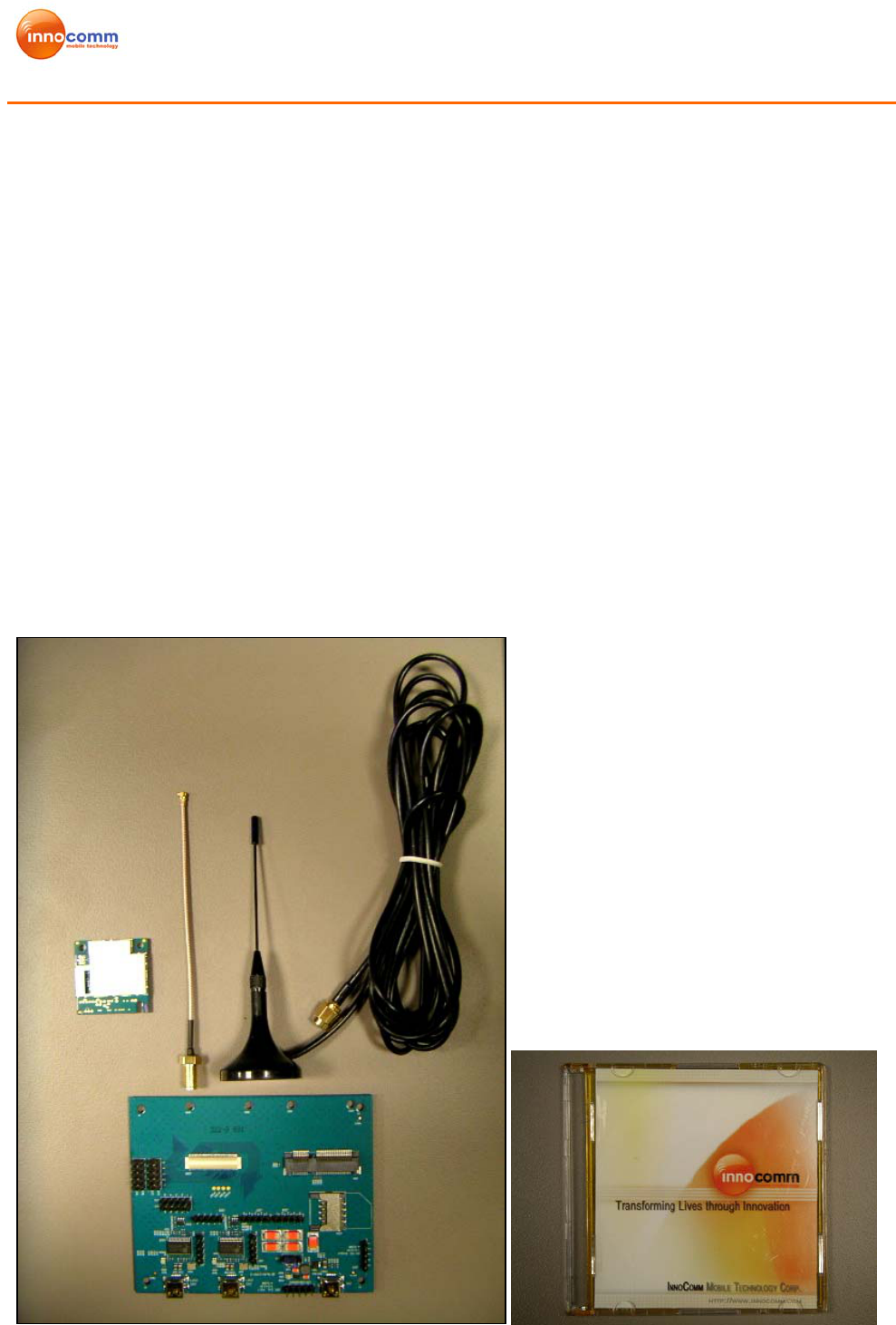
1.1. Development Kit Content
The development kit for Amazon modem module contains following items.
1. Modem Module: Amazon modem module x 1
2. Extension Board x 1
3. RF cable x 1
4. External Antenna x 1
5. SW driver disk x 1
Figure 1-1 Development Kit Content
Amazon Modem Module
Development Kit User Manual
Ver1.1 7/26/2010
1.2. Amazon modem module and Extension board photo
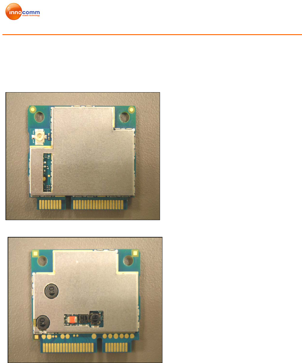
1.2.1. Amazon 1: PCI-E Type
Figure 1-2 Amazon1 TOP
Figure 1-3 Amazon1 BOTTOM
Amazon Modem Module
Development Kit User Manual
Ver1.1 7/26/2010
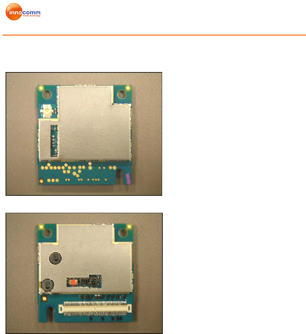
1.2.2. Amazon 2: BTB Connector Type
Figure 1-4 Amazon2 TOP
Figure 1-5 Amazon2 BOTTOM
Amazon Modem Module
Development Kit User Manual
Ver1.1 7/26/2010
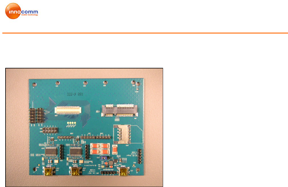
1.2.3. Extension Board
Figure 1-6 Extension Board
2. HW TEST SETUP
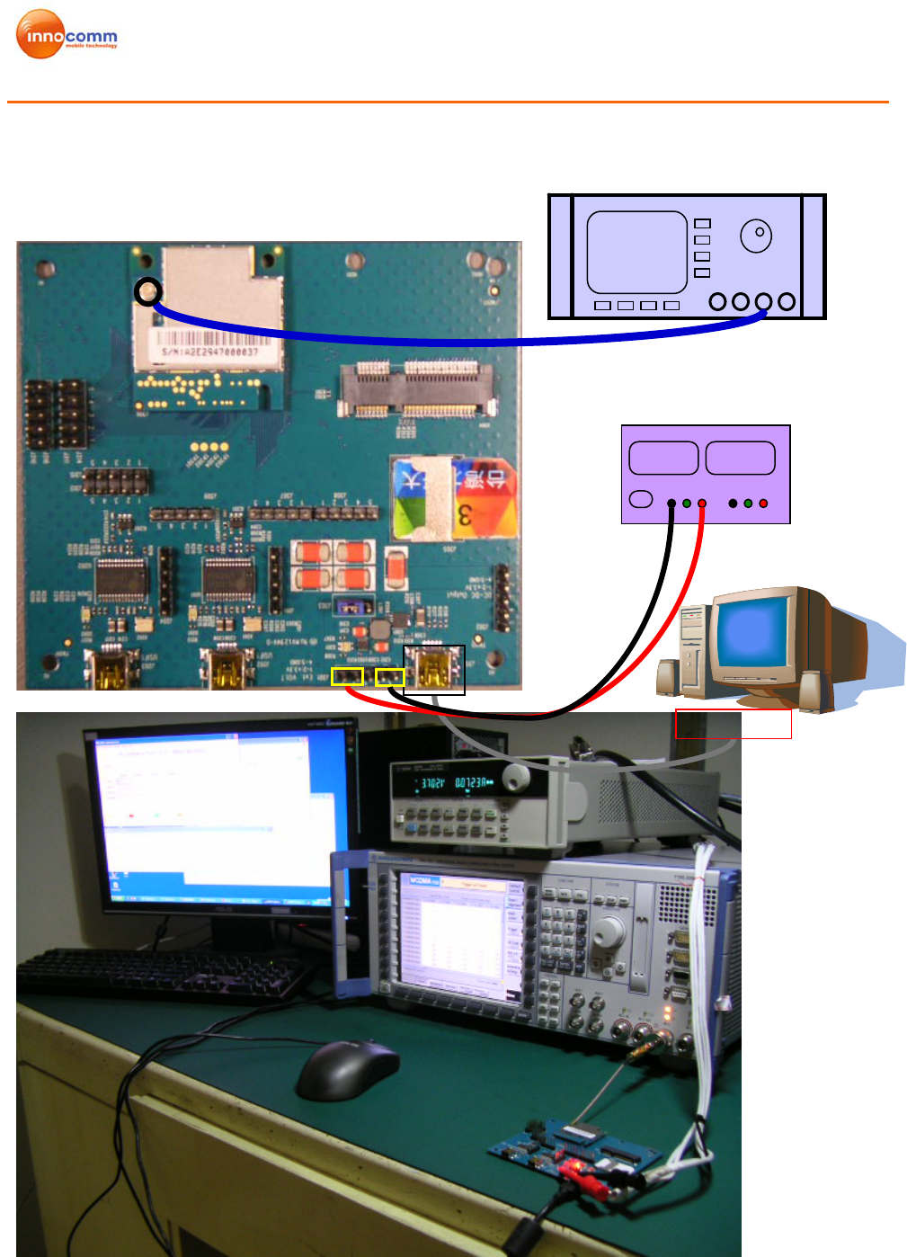
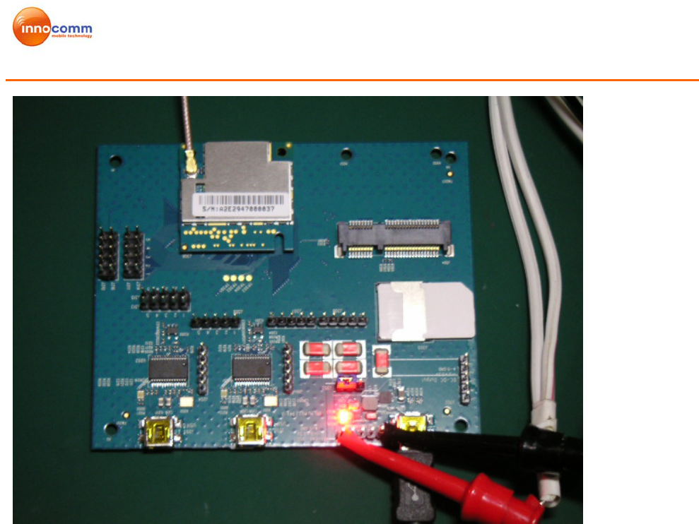
2.1. Connect PC USB Port to Extension Board USB Connector
Application: Test with Instrument (CMU200, Agilent 8960…) or Real network test
Requirement:
SW: Driver, CM (Connection manager) installation
HW: Test SIM for test with Instrument (CMU200, Agilent8960….etc) x1
Real SIM for test with Real network (Via external antenna) x1
Power supply x 1
Input voltage --- 3.3 V for Amazon 1
--- 3.7 V for Amazon 2
Instrument or external antenna x1
RF cable x 1
USB cable x1
Amazon Modem Module
Development Kit User Manual
Ver1.1 7/26/2010
+3.7 +3.7
DC POWER SUPPLY
CMU200
PC
USB PORT
RF cable
Power cable
USB cable
(
to USB
)
Amazon Modem Module
Development Kit User Manual
Ver1.1 7/26/2010
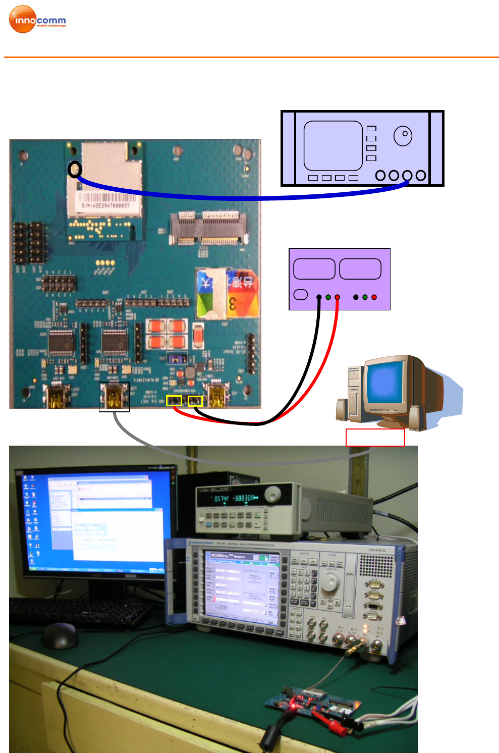
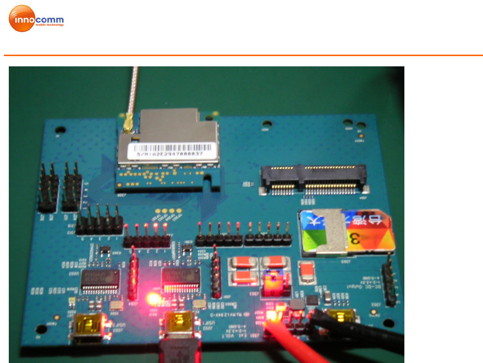
2.2. Connect PC USB Port to Extension Board USIF 1 Port
Application: Test with Instrument (CMU200, Agilent 8960…)
Requirement:
SW: Driver
HW: Test SIM card x 1
Power supply x 1
Input voltage --- 3.3 V for Amazon 1
--- 3.7 V for Amazon 2
Instrument (CMU200, Agilent8960….etc) x1
RF cable x 1
USB cable x 1
Amazon Modem Module
Development Kit User Manual
Ver1.1 7/26/2010
Power cable
RF cable
+3.7V +3.7V
DC POWER SUPPLY
CMU200
PC
USB PORT
USB cable (to USIF1)
Amazon Modem Module
Development Kit User Manual
Ver1.1 7/26/2010
3. SW TEST SETUP
3.1 Driver Installation
3.1.1. HS-USB Driver Installation
The HS-USB driver should be installed when using USB Port. Following are the steps for
installation.
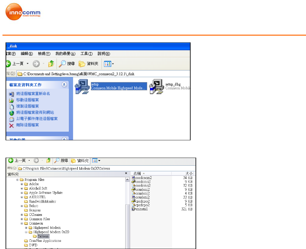
Step 1: Unzip and install the driver. File name: WMC_Comneon2_3.12.1 Driver\
Setup.exe. Then it will create one folder under C:\Program
Files\Comneon\Highspeed Modem 0x20\Drivers\.
Amazon Modem Module
Development Kit User Manual
Ver1.1 7/26/2010
Figure 3-1 Setup.exe
Figure 3-2 Driver folders
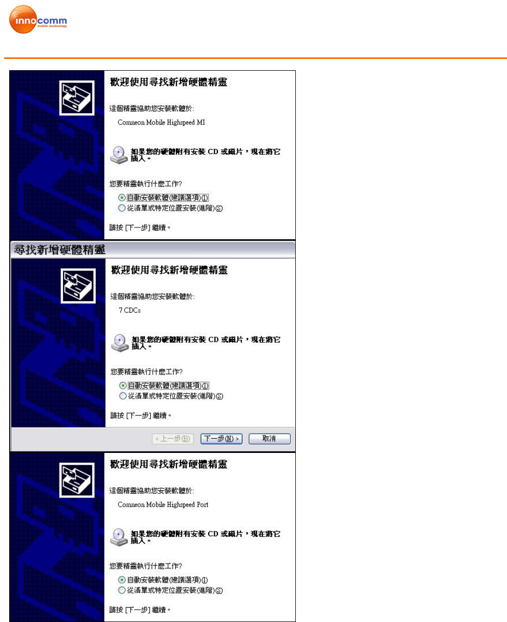
Step 2: Connect UE device to PC with USB2.0 cable, and power on device
Step 3: Install HS_USB Driver to PC. When device powered on and PC detect the
device. The driver will install automatically or set direction to C:\Program
Files\Comneon\Highspeed Modem 0x20\Drivers\
Amazon Modem Module
Development Kit User Manual
Ver1.1 7/26/2010
Figure 3-3: Auto installations
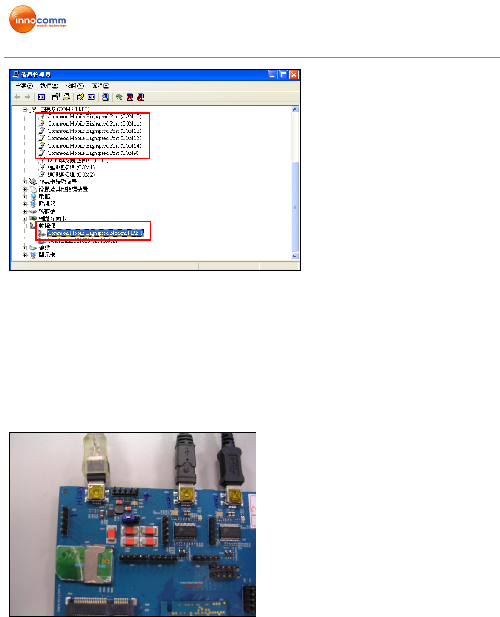
6 virtual ports will be installed. (Comneon Mobile Highspeed Port), and One Modem Port.
(Comneon Mobile Highspeed Modem MPE1)
Amazon Modem Module
Development Kit User Manual
Ver1.1 7/26/2010
Figure 3-4 Virtual Ports
3.1.2. Prolific Driver Installation
The Prolific Driver should be installed when using USIF 1 or USIF 5 Port. Following are the
steps for installation.
Step 1: Unzip and install File name: PL2303_Prolific_DriverInstaller_v10518.exe.
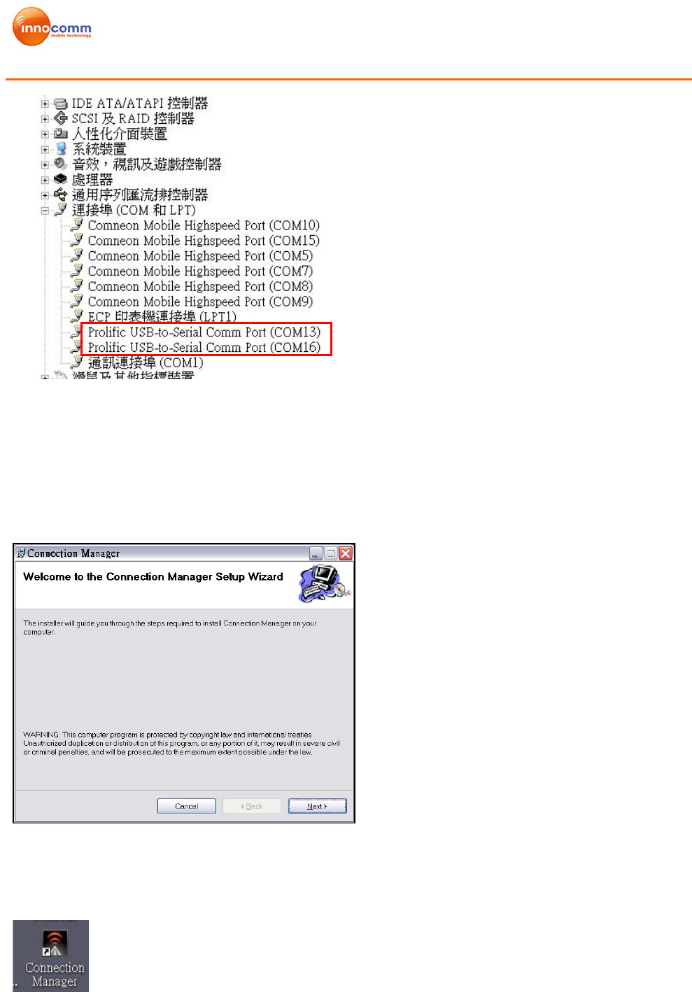
Step 2: Plug in USIF1 or USIF 5. PC will detect USB to Serial Ports and install the
driver automatically.
Figure 3-5 USIF1 and USIF 5 Port
USIF 1 USIF 5 HS_USB
Amazon Modem Module
Development Kit User Manual
Ver1.1 7/26/2010
Figure 3-6 USB to Serial Ports
3.1.3. Connection Manager Installation
Step1: Unzip ProjAmazonSetup.rar and install ProjP330Setup.
Figure 3-7 Connection Manager Installation
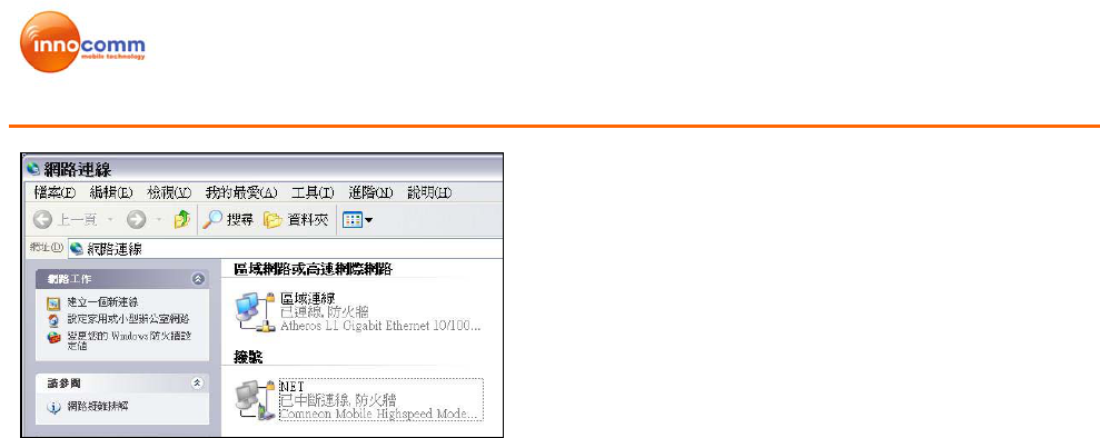
Step 2: Execute Connection Manager on desktop. A Network Connection, NET, will
be created and modem should be “Comneon Mobile Highspeed Modem”.
Figure 3-8 Connection Manager Icon
Amazon Modem Module
Development Kit User Manual
Ver1.1 7/26/2010
Figure 3-9 Network Connection
3.2 Connection Manager
Connection Manager is used to perform network data link and SMS function.
Following are basic descriptions of each icon in main menu.
Home:
Back to Main Menu
SMS:
- Create new message
- List, read/edit Phone Book from SIM, Outlook list.
- Inbox, read/reply/ delete from SMS storage.
- Draft, save draft SMS in CM
- Outbox, template storage when unable to sent SMS
- Sent, see sent message in CM
Data Link:
Connection/ Disconnection Data call to network
CM setting:
-SMS, include storage, SMSC number setting, and SMS valid period
-Profile, Operator APN setting (default is “internet”)
-Network, Setting camping method, GSM/ UMTS selection, Fight mode switch, PIN
lock.
- Data,
--Data usage, Limit total Data transfer
--History, record Data connection history
-Sys Info, Device IMEI, SW information
-Debug, AT command line and history, HW control (power on/off, Radio on/off, Card
reset).
Device status Bar:
Show device status. (Not detected, Camping, Data link success…)
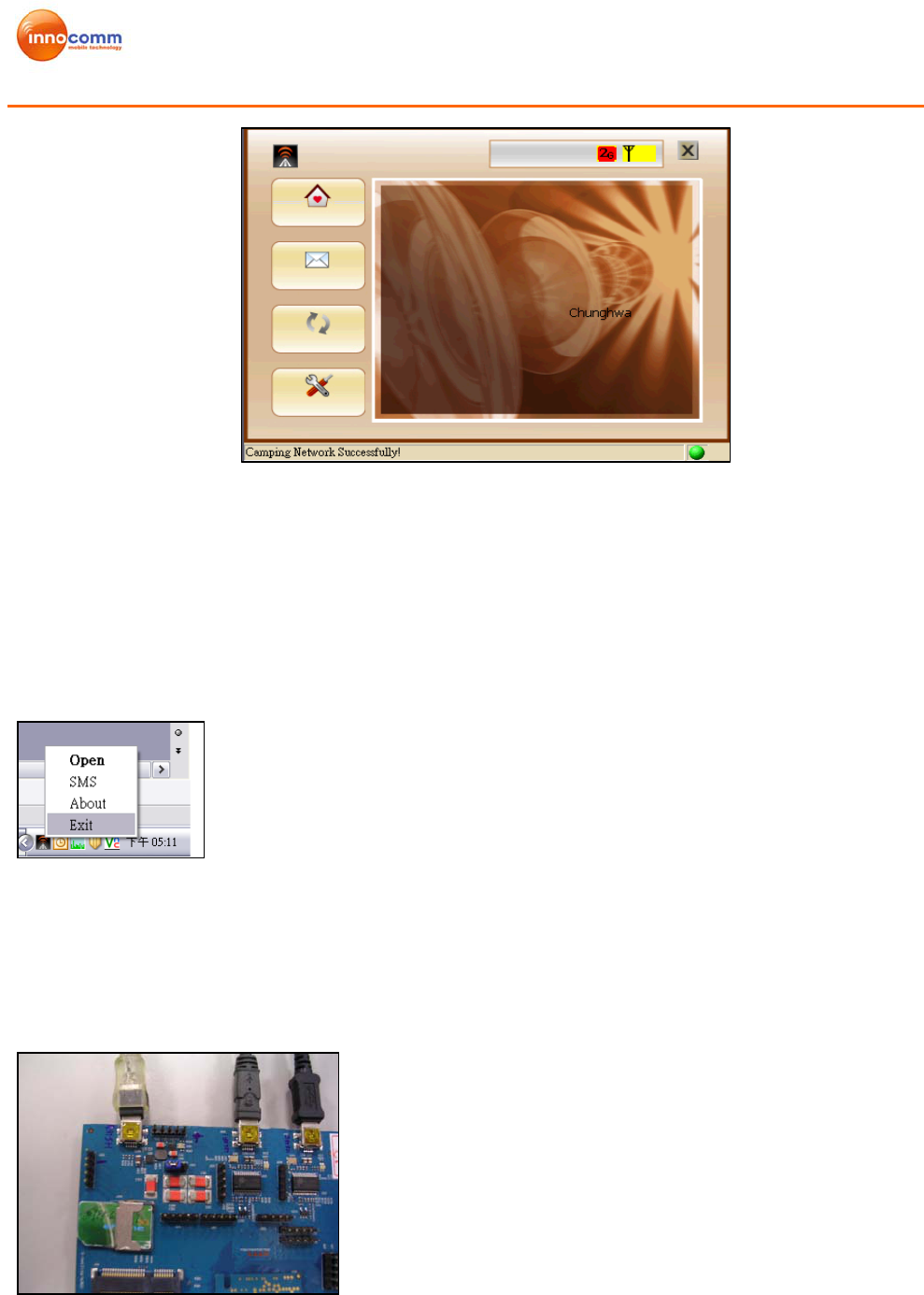
Figure 3-10 shows the main menu icons
Amazon Modem Module
Development Kit User Manual
Ver1.1 7/26/2010
Figure 3-10 Main Menu Screen
Note:
1. Please use “Exit” to quit CM. Tape the “x” on the window is to minimize CM into
Windows application try, and it will not quit the CM. (See Figure 3-11)
2. Do not Open CM twice at same time. Modem com port will be hold when another CM is
running.
Figure 3-11 correct way to quit CM
3.3 Connection With Test Instrument
Following steps show how to connect device to test instrument.
Step 1: Plug in USIF 1 port.
Figure 3-12 USIF 1 port
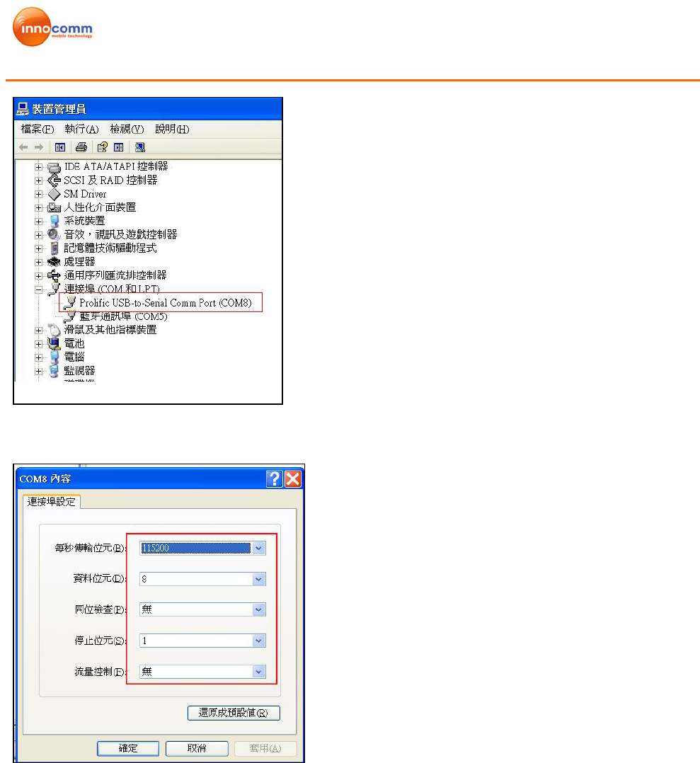
Step 2: PC detects Prolific_USB -to- Serial Comm Port. (See Figure 3-13)
Home
SMS
Data link
CM
Setting Device status Bar
USIF 1
Amazon Modem Module
Development Kit User Manual
Ver1.1 7/26/2010
Figure 3-13 Prolific_USB -to- Serial Comm Port
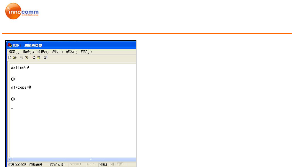
Step 3: Set up HyperTerminal as Figure 3-14.
Figure 3-14 Hyper Terminal Settings
Step 4: Send AT Command via HyperTerminal as Figure 3-15
Amazon Modem Module
Development Kit User Manual
Ver1.1 7/26/2010
Figure 3-15 Send AT command
Reference AT commands are as following:
1. Auto-search Network: AT+COPS=0
2. Make a circuit-switch call to instrument: ATD123456; (Do not miss the semicolon.)
3. In case, if SIM is locked by PIN number (e.g., 0000), use AT+CPIN=”0000” to unlock
SIM PIN. Before unlock, the SIM PIN Lock will also cause ERROR when issuing
AT+COPS=0. (Use AT+CPIN? to query the PIN status if you are not sure the SIM
requires PIN or not.)
Amazon Modem Module
Development Kit User Manual
Ver1.1 7/26/2010
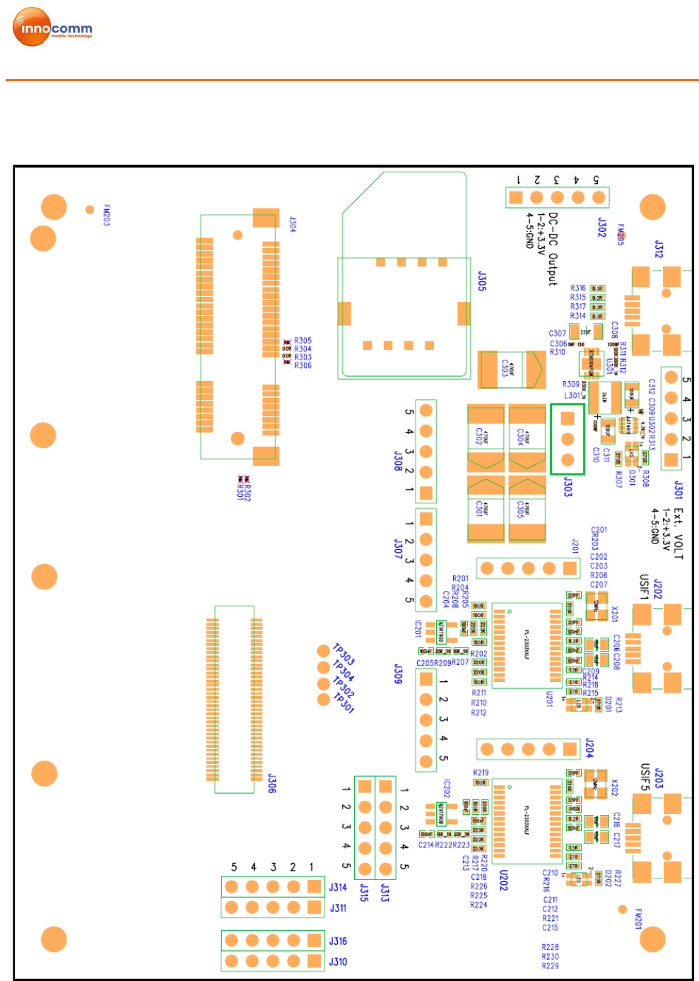
Appendix 1: Detail description of Extension board
1. Placement
CAUTION:
DO NOT insert Amazon1 and Amazon2 Modules at the same time!

Amazon Modem Module
Development Kit User Manual
Ver1.1 7/26/2010
2. Connector
J312 : USB port
J202 : USIF1 Port to USB
J203 : USIF5 port to USB
J304 : PCI-E Slot
J305 : SIM card connector
J306 : BTB connector
3. Jumper
J201 : USIF1 signal
Pin1 : TXD (X-GOLD 616 output)
Pin2 : RXD (X-GOLD 616 input)
Pin3 : RTS (X-GOLD 616 output)
Pin4 : CTS (X-GOLD 616 input)
Pin5 : GND
J204 : USIF5 signal
Pin1 : TXD (X-GOLD 616 output)
Pin2 : RXD (X-GOLD 616 input)
Pin3 : RTS (X-GOLD 616 output)
Pin4 : CTS (X-GOLD 616 input)
Pin5 : GND
J301 : External voltage input
Pin1 : Input 3.3V for Amazon 1 and 3.7V for Amazon 2
Pin2 : Input 3.3V for Amazon 1 and 3.7V for Amazon 2
Pin3 : NC
Pin4 : GND
Pin5 : GND
J302 : DC to DC convertor output
Pin1 : Output
Pin2 : Output
Pin3 : NC
Pin4 : GND
Pin5 : GND
J303 : Power select
Pin1-2 short : power from USB (J312)
Pin 2-3 short: power from jumper (J301)---Default
J307 : SPI test pin
Pin1 : SPI_SOMI
Pin2 : SPI_SIMO
Pin3 : SPI_CLK
Pin4 : SPI_CS
Pin5 : GND
J308 : AGPS control test pin
Pin1 : AGPS_BLANKIUNG
Pin2 : AGPS_REFCLK
Pin3 : AGPS_SYNC
Pin4 : PIN16
Pin5 : GND

Amazon Modem Module
Development Kit User Manual
Ver1.1 7/26/2010
J309 : PCM test pin
Pin1 : PCM_CLK
Pin2 : PCM_UL
Pin3 : PCM_DL
Pin4 : PCM_SYNC
Pin5 : GND
J310 : Control test pin
Pin1 : SRDY
Pin2 : MRDY
Pin3 : USB_ON
Pin4 : SIM_OFF
Pin5 : GND
J311 : I2S test pin
Pin1 : I2S2_CLK
Pin2 : I2S2_RX
Pin3 : I2S2_TX
Pin4 : I2S2_SYNC
Pin5 : GND
J313 : GPIO test pin
Pin1 : GPIO1
Pin2 : GPIO2
Pin3 : GPIO3
Pin4 : SIM_CD
Pin5 : GND
J314 : CLOCK test pin
Pin1 : FSYS2_CLK
Pin2 : FSYS2_EN
Pin3 : FSYS3_CLK
Pin4 : FSYS3_EN
Pin5 : GND
J315 : Control test pin
Pin1 : RF_PA_ON
Pin2 : RST_XMM6160
Pin3 : DBR_BLANKING
Pin4 : PWR_FAIL
Pin5 : GND
J316 : Control test pin
Pin1 : TX_PWR_TH
Pin2 : CLKOUT2
Pin3 : NC
Pin4 : FSYS4_CLK
Pin5 : GND
Appendix 2: Federal Communications Commission (FCC)
Statement
This device complies with part 15 of the FCC Rules. Operation is subject to the following
two conditions: (1) This device may not cause harmful interference, and (2) this device
must accept any interference received, including interference that may cause undesired
operation.
This device has been tested and found to comply with the limits for a Class B digital device,
pursuant to Part 15 of the FCC Rules. These limits are designed to provide reasonable
protection against harmful interference in a residential installation. This equipment
generates, uses and can radiated radio frequency energy and, if not installed and used in
accordance with the instructions, may cause harmful interference to radio communications.
However, there is no guarantee that interference will not occur in a particular installation If
this equipment does cause harmful interference to radio or television reception, which can
be determined by turning the equipment off and on, the user is encouraged to try to correct
the interference by one or more of the following measures:
-Reorient or relocate the receiving antenna.
-Increase the separation between the equipment and receiver.
-Connect the equipment into an outlet on a circuit different from that to which the receiver
is connected.
-Consult the dealer or an experienced radio/TV technician for help.
Changes or modifications not expressly approved by the party responsible for compliance
could void the user‘s authority to operate the equipment.
4RF Exposure Information
This Modular Approval is limited to OEM installation for mobile and fixed applications
only. The antenna installation and operating configurations of this transmitter, including
any applicable source-based time-averaging duty factor, antenna gain and cable loss must
satisfy MPE categorical Exclusion Requirements of §2.1091.
The antenna(s) used for this transmitter must be installed to provide a separation distance
of at least 20 cm from all persons, must not be collocated or operating in conjunction with
any other antenna or transmitter, except in accordance with FCC multi-transmitter product
procedures.
The end user has no manual instructions to remove or install the device and a separate
approval is required for all other operating configurations, including portable configurations
with respect to 2.1093 and different antenna configurations.
Maximum antenna gain allowed for use with this device is -0.95 dBi.
When the module is installed in the host device, the FCC ID label must be visible through
a window on the final device or it must be visible when an access panel, door or cover is
easily re-moved. If not, a second label must be placed on the outside of the final device
that contains the following text: “Contains FCC ID: YAI-AZ1901”.