InnoComm Mobile Technology BM05-AN BT4.0 LE Module User Manual Module 20140909
InnoComm Mobile Technology Corporation BT4.0 LE Module Module 20140909
User Manual.pdf
InnoComm Mobile Technology Corporation
3F, No. 6, Hsin Ann Rd., Hsinchu Science Park, Hsinchu 30078, Taiwan
TEL: +886-3-5781868 FAX: +886-3-5781187
BT4.0 Low Energy Module
User Manual
FCC ID: YAIBM05-AN

Introduction
This document describes pin definition, mechanical drawing and reflow data of
Bluetooth Low Energy Module and hope it can helps designer to design in easier
and manufacturing smoothly.
Pin Definition
Pin#PinNameDirectionVoltage
Desription
1
VDD
I
1.8to 3.3V Input power can range from 1.8V to3.3V
2
VSS
I
GND
Ground
3
TEST0
I/O
1.8V to 3.3V Mfg Test pin 0; MODE "POINTER". Internally
pulled-up (active low)
4
TEST1
I/O
1.8V to 3.3V Mfg Test pin 1; MODE "JOYSTICK". Internally
pulled-up (active low)
5
SDA
I/O
1.8V to 3.3V I2C data to interface with sensors (gyro&
accelerometer)forrelative
motion.MayalsointerfacetoadditionalI2Cmemory.
6
SCL
O
1.8V to 3.3V I2C clock to interface with sensors(gyro&
accelerometer)forrelative
motion.MayalsointerfacetoadditionalI2Cmemory.
7
TEST2
I/O
1.8V to 3.3V Mfg Test pin 2
8
GPIO_2
I/O
1.8V to 3.3V Interrupt from I2C accelerometer.Internallypulled‐up.
9
GPIO_3
I/O
1.8V to 3.3V Interrupt from I2C gyro. Internallypulled‐up.
10GPIO_0
I/O
1.8V to 3.3V "A" button. Internally pulled‐up.
11GPIO_1
I/O
1.8V to 3.3V "B" button. Internally pulled‐up.
12GPIO_4
I/O
1.8V to 3.3V General I/O - UNUSED. Internally pulled-up.
13GPIO_5
I/O
1.8V to 3.3V "HOME" button. Internally pulled‐up.
14GPIO_6
I/O
1.8V to 3.3V "HELP" button. Internally pulled‐up.
15GPIO_7
I/O
1.8V to 3.3V "PAUSE" button. Internally pulled‐up.
16GPIO_10
I/O
1.8V to 3.3V LED for player "1".
17GPIO_11
I/O
1.8V to 3.3V LED for player "2".
18ADC_0
I
1.8V to 3.3V ADC input for X direction on
j
oystick.
19ADC_1
I
1.8V to 3.3V ADC input for Y direction on
j
oystick.
20ADC_2
I
1.8V to 3.3V ADC input for battery voltage.
21GPIO_8
I/O
1.8V to 3.3V Power LED.
22GPIO_9
I/O
1.8V to 3.3V IR LED.
23GPIO_12
I/O
1.8V to 3.3V General I/O ‐UNUSED. Internally pulled‐up.
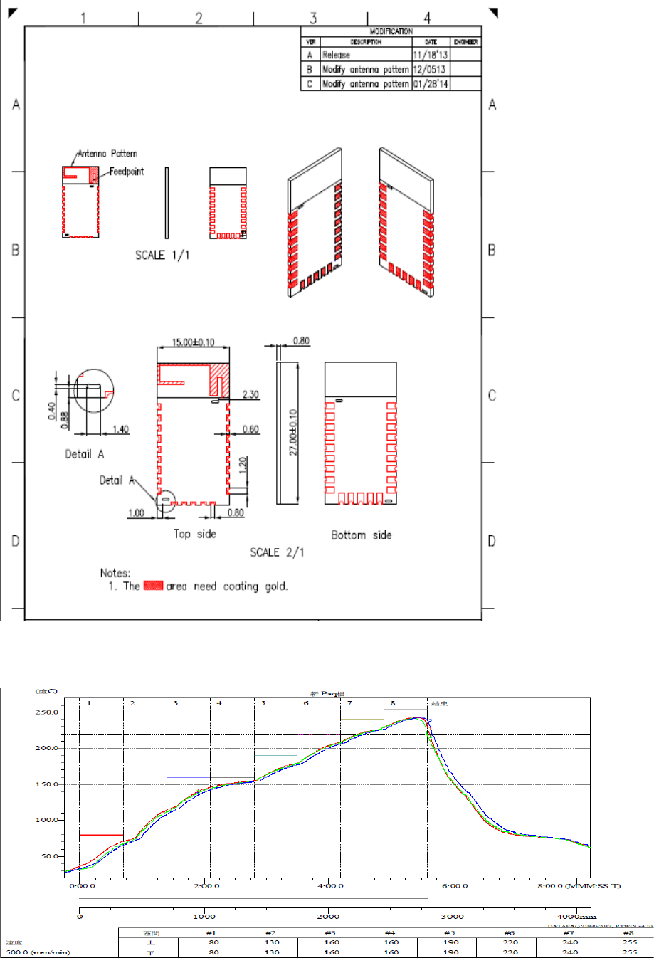
Mechanical Drawing
Reflow data
Federal Communication Commission Interference Statement
ThisdevicecomplieswithPart15oftheFCCRules.Operationissubjecttothe
followingtwoconditions:(1)Thisdevicemaynotcauseharmfulinterference,and
(2)thisdevicemustacceptanyinterferencereceived,includinginterferencethat
maycauseundesiredoperation.
ThisequipmenthasbeentestedandfoundtocomplywiththelimitsforaClassB
digitaldevice,pursuanttoPart15oftheFCCRules.Theselimitsaredesignedto
providereasonableprotectionagainstharmfulinterferenceinaresidential
installation.Thisequipmentgenerates,usesandcanradiateradiofrequencyenergy
and,ifnotinstalledandusedinaccordancewiththeinstructions,maycause
harmfulinterferencetoradiocommunications.However,thereisnoguarantee
thatinterferencewillnotoccurinaparticularinstallation.Ifthisequipmentdoes
causeharmfulinterferencetoradioortelevisionreception,whichcanbe
determinedbyturningtheequipmentoffandon,theuserisencouragedtotryto
correcttheinterferencebyoneofthefollowingmeasures:
‐ Reorientorrelocatethereceivingantenna.
‐ Increasetheseparationbetweentheequipmentandreceiver.
‐ Connecttheequipmentintoanoutletonacircuitdifferentfromthat
towhichthereceiverisconnected.
‐ Consultthedealeroranexperiencedradio/TVtechnicianforhelp.
FCCCaution:Anychangesormodificationsnotexpresslyapprovedbythe
partyresponsibleforcompliancecouldvoidtheuser'sauthoritytooperatethis
equipment.
Thistransmittermustnotbeco‐locatedoroperatinginconjunctionwithanyother
antennaortransmitter.

RadiationExposureStatement:
TheproductcomplywiththeFCCportableRFexposurelimitsetforthforan
uncontrolledenvironmentandaresafeforintendedoperationasdescribedinthis
manual.ThefurtherRFexposurereductioncanbeachievediftheproductcanbe
keptasfaraspossiblefromtheuserbodyorsetthedevicetoloweroutputpower
ifsuchfunctionisavailable.
ThisdeviceisintendedonlyforOEMintegratorsunderthefollowingconditions:
1) Thetransmittermodulemaynotbeco‐locatedwithanyothertransmitteror
antenna.
Aslongas1conditionaboveismet,furthertransmittertestwillnotberequired.
However,theOEMintegratorisstillresponsiblefortestingtheirend‐productfor
anyadditionalcompliancerequirementsrequiredwiththismoduleinstalled
IMPORTANTNOTE:Intheeventthattheseconditionscannotbemet(forexample
certainlaptopconfigurationsorco‐locationwithanothertransmitter),thentheFCC
authorizationisnolongerconsideredvalidandtheFCCIDcannotbeusedonthe
finalproduct.Inthesecircumstances,theOEMintegratorwillberesponsiblefor
re‐evaluatingtheendproduct(includingthetransmitter)andobtainingaseparate
FCCauthorization.
EndProductLabeling
Theproductcanbekeptasfaraspossiblefromtheuserbodyorsetthedeviceto
loweroutputpowerifsuchfunctionisavailable.Thefinalendproductmustbe
labeledinavisibleareawiththefollowing:“ContainsFCCID:YAIBM05‐AN”.The
grantee'sFCCIDcanbeusedonlywhenallFCCcompliancerequirementsaremet.
ManualInformationTotheEndUser
TheOEMintegratorhastobeawarenottoprovideinformationtotheenduser
regardinghowtoinstallorremovethisRFmoduleintheuser’smanualoftheend
productwhichintegratesthismodule.
Theendusermanualshallincludeallrequiredregulatoryinformation/warningas
showinthismanual.