InnoComm Mobile Technology BM15R2 BLE Single Mode Module User Manual Manual
InnoComm Mobile Technology Corporation BLE Single Mode Module Manual
Manual
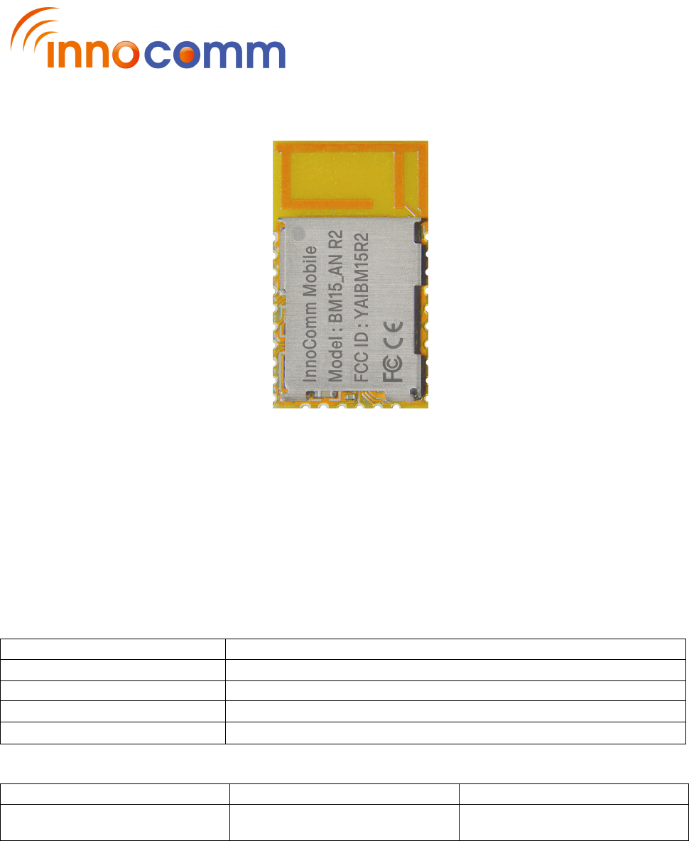
BM15_AN R2 BLE Single Mode Module
Product Specification
Model Name
BM15_AN R2
Project code
Description
BLE Single Mode Module
Revision
1.4
Issue Date
2017/09/26
Approved by
Reviewed by
Issued by
Harrison Chen Taka Wei Aaron Lai

iCOM_BM15_AN R2 Module Product Specification
REV 1.4 9/26/2017
InnoComm Mobile Technology Confidential
2
/
19
Revision History
Revision
Released Date Comments/Remark Author
1.0 2017/03/07 Initial release Aaron Lai
1.1 2017/03/29 Update reflow profile Aaron Lai
1.2 2017/06/07 Update module photo and correct content
typo
Aaron Lai
1.3 2017/07/10 Update GPIO pin 31 description and
Reference Circuit
Aaron Lai
1.4 2017/09/26 Update ME drawing, layout and placement
section
Aaron Lai
® 2017 InnoComm Mobile Technology Corp.
Disclaimer
BM15_AN R2 BLE MODULE are supplied “as is” and without warranties of any kind, express, implied, or
statutory including, but not limited to, any implied warranty for a particular purpose. No license is granted by
implication or otherwise under any patents or other intellectual property by application or use of evaluation
boards. Information furnished by InnoComm is believed to be accurate and reliable. InnoComm reserves the
right to change specifications or product description in this document at any time without notice.
Should Buyer purchase or use InnoComm’s products for any such unintended or unauthorized application,
Buyer shall indemnify and hold InnoComm harmless against all claims and damages.
InnoComm is the trademarks of InnoComm Mobile Technology Corp.
Other trademarks and registered trademarks mentioned herein are the property of their respective owners.

iCOM_BM15_AN R2 Module Product Specification
REV 1.4 9/26/2017
InnoComm Mobile Technology Confidential
3
/
19
TABLE OF CONTENT
1. INTRODUCTION ......................................................................................... 4
2. GENERAL INFORMATION ........................................................................ 5
2.1 KEY FEATURES .................................................................................................... 5
2.2 BLOCK DIAGRAM ................................................................................................. 7
3. PIN MAP AND SIGNAL DESCRIPTION .................................................... 8
3.1 REFERENCE CIRCUIT .......................................................................................... 9
4. ELECTRICAL CHARACTERISTICS ........................................................ 10
4.1 RECOMMENDED OPERATING RANGE ............................................................. 10
4.2 POWER CONSUMPTION .................................................................................... 10
5. RF CHARACTERISTICS .......................................................................... 11
6. MECHANICAL INFORMATION ......................................................... …..12
7. PCB LAYOUT RECOMMENDATION ...................................................... 13
8. MODULE PLACEMENT LAYOUT GUIDE............................................... 14
9. SMT SOLDER REFLOW RECOMMENDATION ..................................... 15
10. PRODUCT AND DOCUMENTATION SUPPORT...................................16
10.1 DEVELOPMENT SUPPORT .............................................................................. 16
10.2 DOCUMENTATION SUPPORT .......................................................................... 17
10.3 COMMUNITY RESOURCES .............................................................................. 17
Federal Communication Commission Interference Statement ................... 18

iCOM_BM15_AN R2 Module Product Specification
REV 1.4 9/26/2017
InnoComm Mobile Technology Confidential
4
/
19
1. INTRODUCTION
Based on TI’s outstanding CC2640R2 BLE technology, Innocomm’s BM15_AN R2 module is a wireless
microcontroller (MCU) targeting Bluetooth® 4.2 and Bluetooth 5 low-energy applications.
It is with very low active RF and MCU current and low-power mode current consumption provide excellent
battery lifetime and allow for operation on small coin cell batteries and in energy-harvesting applications and
embedded PCB antenna.
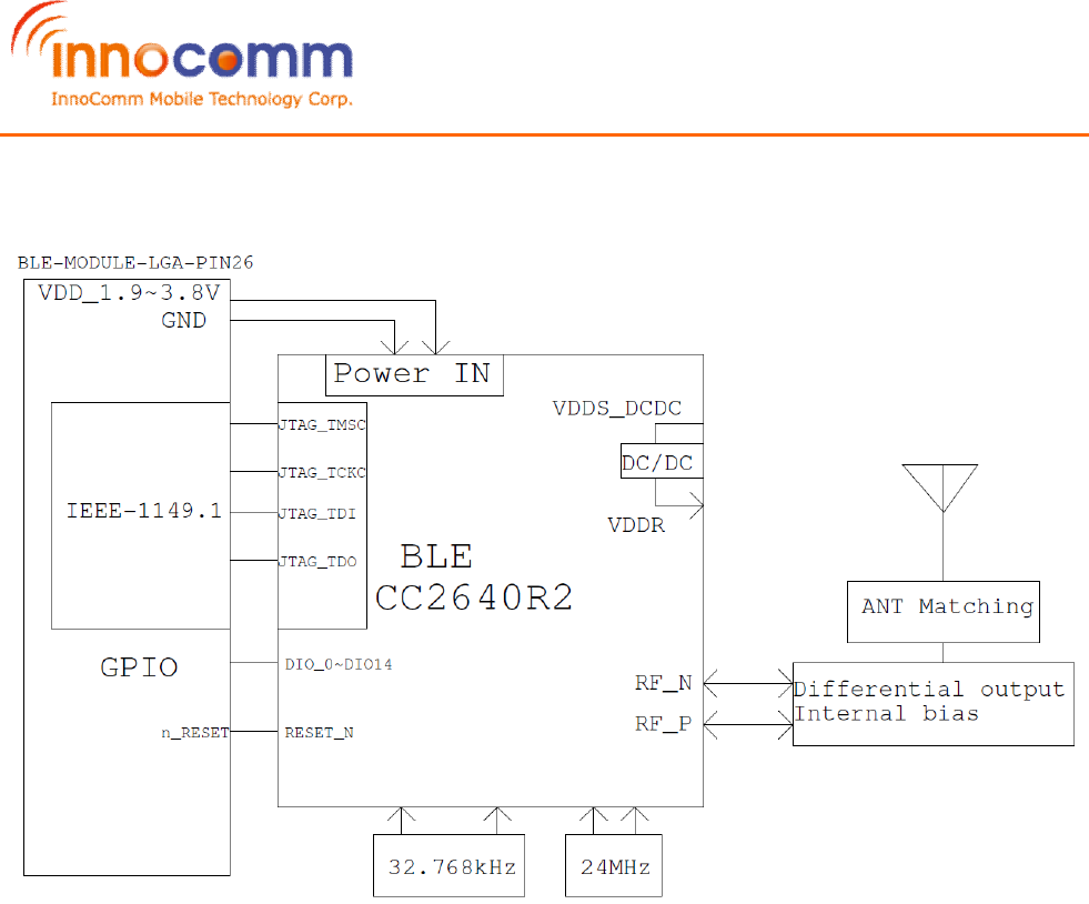
BM15_AN R2 module contains a powerful 32-bit Cortex M3 running up to 48 MHz as the main processor and
a rich peripheral feature set that includes a unique ultra-low power sensor controller.
Bluetooth low energy controller and host libraries are embedded in ROM and run partly on an
ARM® Cortex®-M0 processor. This architecture improves overall system performance and power
consumption and frees up significant amounts of flash memory for the application.

iCOM_BM15_AN R2 Module Product Specification
REV 1.4 9/26/2017
InnoComm Mobile Technology Confidential
5
/
19
2. General Information
2.1 Key Features
RF
• 2.4-GHz RF Transceiver Compatible With Bluetooth low energy (BLE) 4.2 and 5 Specifications
• Supports data rates between 1 Mbps
• Programmable output power up to +5 dBm
• Excellent Receiver Sensitivity (–97 dBm for BLE), Selectivity, and Blocking Performance
• Suitable for Systems Targeting Compliance With Worldwide Radio Frequency Regulations
– ETSI EN 300 328 (Europe)
– EN 300 440 class 2 (Europe)
– FCC CFR47 Part 15 (US)
– ARIB STD-T66 (Japan)
Layout
• Few External Components
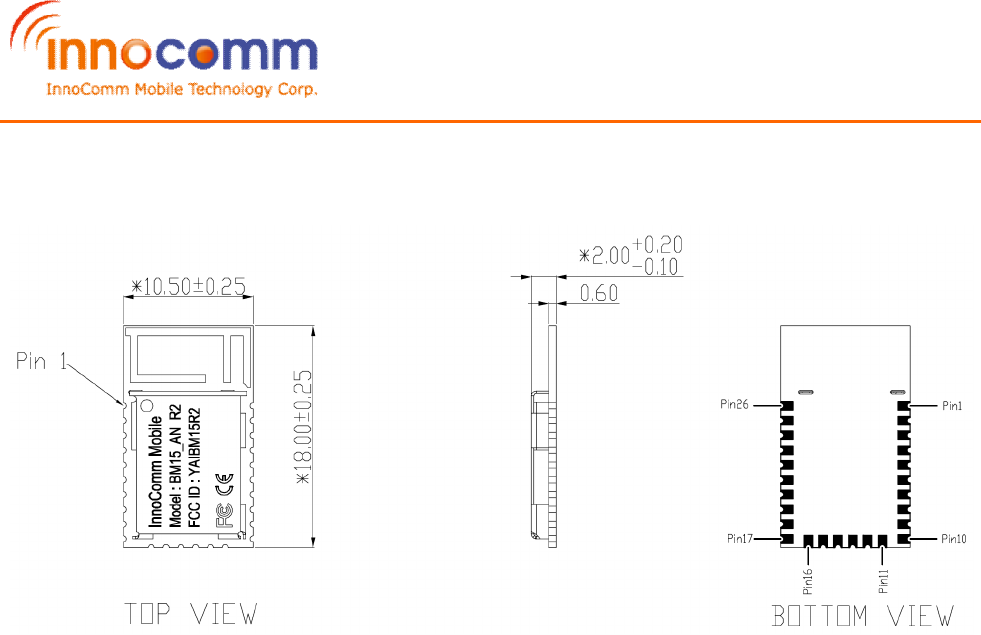
• 18.0 mm × 10.5 mm × 2.0 mm, 26 pin LCC Package
Low Power
• Wide supply voltage range : 1.9 – 3.8V
• Differential RF mode : 6.4±3 mA
• Differential RF mode TX at 0 dBm: 6.8±0.3 mA
• Differential RF mode TX at +5 dBm: 8.9±0.3mA
• Low Power Mode: 1 μA (RTC Running + RAM/CPU retention)
• Low Power Mode: 100 nA (Flash retention)
Peripherals
• Integrated Temperature Sensor
• Four General-Purpose Timer Modules (Eight 16-Bit or Four 32-Bit Timers, PWM Each)
• 12-bit ADC, 200-ksamples/s, 8-Channel Analog MUX
• Ultra-Low-Power Analog Comparator
• UART
• 2x SSI (SPI, MICROWIRE, TI)
• Ultra-low power
• I2C, I2S
• Real-time clock
• AES-128 security module
• 15 GPIOs
• Support for 8 capacitive sensing channels
Application
• Home and Building Automation
– Connected Appliances
– Lighting
– Locks
– Gateways
– Security Systems
• Industrial
– Logistics
– Production and Manufacturing Automation
– Asset Tracking and Management

iCOM_BM15_AN R2 Module Product Specification
REV 1.4 9/26/2017
InnoComm Mobile Technology Confidential
6
/
19
– HMI and Remote Display
– Access Control
• Retail
– Beacons
– Advertising
– ESL and Price Tags
– Point of Sales and Payment Systems
• Health and Medical
– Thermometers
– SpO2
– Blood Glucose and Pressure Meters
– Weight Scales
– Hearing Aids
• Sports and Fitness
– Activity Monitors and Fitness Trackers
– Heart Rate Monitors
– Running and Biking Sensors
– Sports Watches
– Gym Equipment
– Team Sports Equipment
• HID
– Voice Remote Controls
– Gaming
– Keyboards and Mice
iCOM_BM15_AN R2 Module Product Specification
REV 1.4 9/26/2017
InnoComm Mobile Technology Confidential
7
/
19
2.2 Block Diagram

iCOM_BM15_AN R2 Module Product Specification
REV 1.4 9/26/2017
InnoComm Mobile Technology Confidential
8
/
19
3. PIN Map and Signal Description
Pin # Pin Name Direction/Type
Description
1 GND Power Ground
2 DIO_0 Digital I/O GPIO, Sensor Controller
3 DIO_1 Digital I/O GPIO, Sensor Controller
4 DIO_2 Digital I/O GPIO, Sensor Controller, high-drive capability
5 DIO_3 Digital I/O GPIO, Sensor Controller, high-drive capability
6 DIO_4 Digital I/O GPIO, Sensor Controller, high-drive capability
7 JTAG_TMSC Digital I/O JTAG TMSC, high-drive capability
8 JTAG_TCKC Digital I/O JTAG_TCKC
9 JTAG_TDO Digital I/O GPIO, High drive capability, JTAG_TDO
10 JTAG_TDI Digital I/O GPIO, High drive capability, JTAG_TDI
11 GND Power Ground
12 GND Power Ground
13 nRESET Digital input Reset, active-low, with internal pull-up
14 DIO_7 Digital/Analog I/O GPIO, Sensor Controller, Analog
15 DIO_8 Digital/Analog I/O GPIO, Sensor Controller, Analog
16 DIO_9 Digital/Analog I/O GPIO, Sensor Controller, Analog
17 DIO_10 Digital/Analog I/O GPIO, Sensor Controller, Analog
18 DIO_11 Digital/Analog I/O GPIO, Sensor Controller, Analog
19 DIO_12 Digital/Analog I/O GPIO, Sensor Controller, Analog
20 DIO_13 Digital/Analog I/O GPIO, Sensor Controller, Analog
21 DIO_14 Digital/Analog I/O GPIO, Sensor Controller, Analog
22 VDD Power 1.9V to 3.8V main chip supply
23 GND Power Ground
24 GND Power Ground
25 GND Power Ground
26 GND Power Ground
iCOM_BM15_AN R2 Module Product Specification
REV 1.4 9/26/2017
InnoComm Mobile Technology Confidential
9
/
19
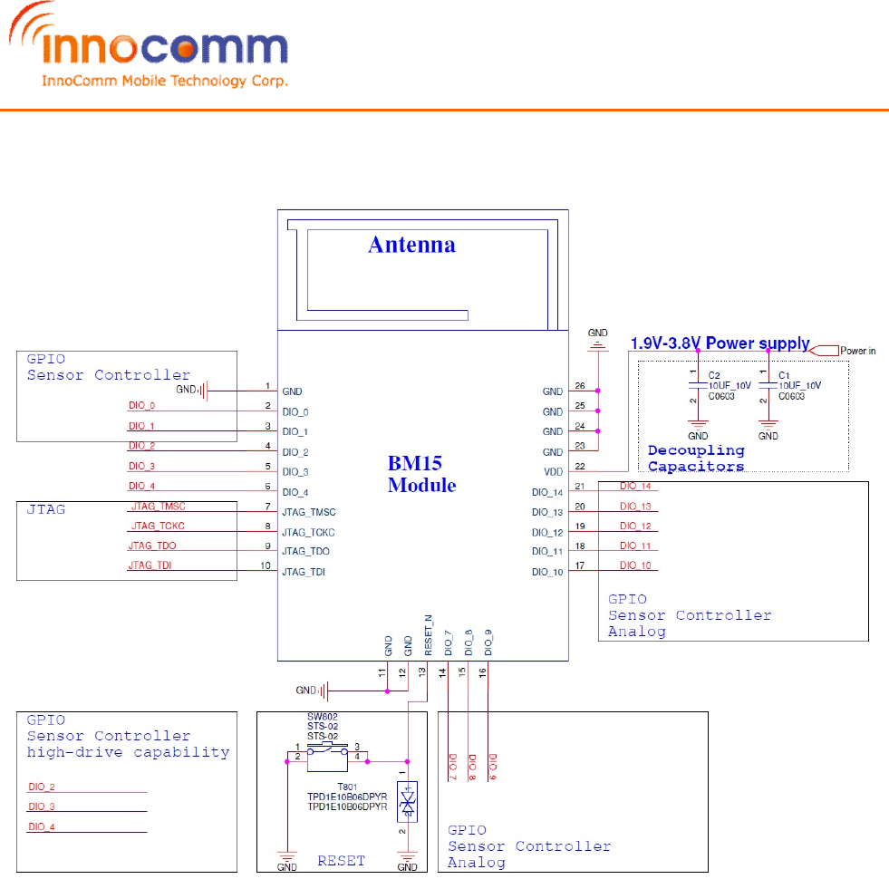
3.1 Reference Circuit
iCOM_BM15_AN R2 Module Product Specification
REV 1.4 9/26/2017
InnoComm Mobile Technology Confidential
10
/
19
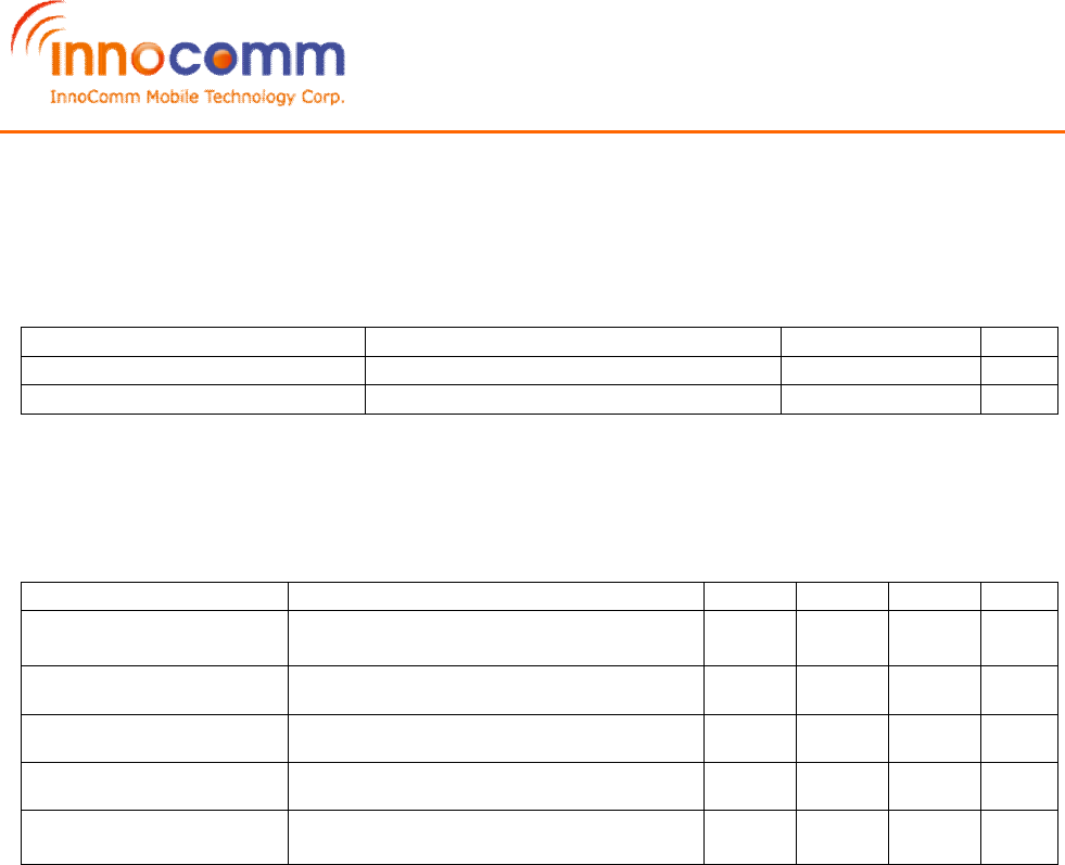
4. ELECTRICAL CHARACTERISTICS
4.1 Recommended Operating Range
PARAMETER
CONDITIONS
MIN NOM MAX
UNIT
Operating ambient temperature range, TA
–40 85
°C
Operating supply voltage For operation in battery-powered and 3.3V systems
1.9 3.8
V
4.2 Power Consumption
Unless noted, all specifications are at 25 °C and Vbat = 3.0 V.
PARAMETER
TEST CONDITIONS
MIN
TYP
MAX
UNIT
Low Power Mode (LPM4.5)
Shutdown. No clocks running, no retention
100 nA
Low Power Mode (LPM3)
With RTC, CPU, RAM and (partial) register retention
1 uA
Power consumption radio RX(2)
With DC/DC
6.1 6.4 6.7 mA
Power consumption radio TX(2)
With DC/DC, 0 dBm output power
6.5 6.8 7.1 mA
Power consumption radio TX(2)
With DC/DC, 5 dBm output power
8.6 8.9 9.2 mA

iCOM_BM15_AN R2 Module Product Specification
REV 1.4 9/26/2017
InnoComm Mobile Technology Confidential
11
/
19
5. RF Characteristics
1 Mbps GFSK (Bluetooth low energy)
Unless noted, all specifications are at 25 °C, Vbat = 3.0 V and fRF = 2440MHz.
PARAMETER
TEST CONDITIONS
MIN
TYP
MAX
UNIT
RX Receiver sensitivity
Differential mode, measured in 50Ω single-ended, BER=10-3
-97
dBm
TX Output power, highest setting
Differential mode, delivered to a single ended 50 Ω load
+5
dBm
TX Output power, lowest setting
Delivered to a single ended 50Ω load
-20 dBm
Spurious emission 30-1000 MHz
Conducted measurement in a 50Ω single ended load.
Complies
with EN 300 328, EN 300 440 class 2, FCC CFR47,
Part 15 and ARIB STD-T-66
-57
dBm
Spurious emission 1-12.75 GHz
-47
dBm
Note: BM15_AN R2 module is with “Internal bias” mode design and related SW setting need to match with
“Internal bias” mode.
iCOM_BM15_AN R2 Module Product Specification
REV 1.4 9/26/2017
InnoComm Mobile Technology Confidential
12
/
19
6. Mechanical Information
iCOM_BM15_AN R2 Module Product Specification
REV 1.4 9/26/2017
InnoComm Mobile Technology Confidential
13
/
19
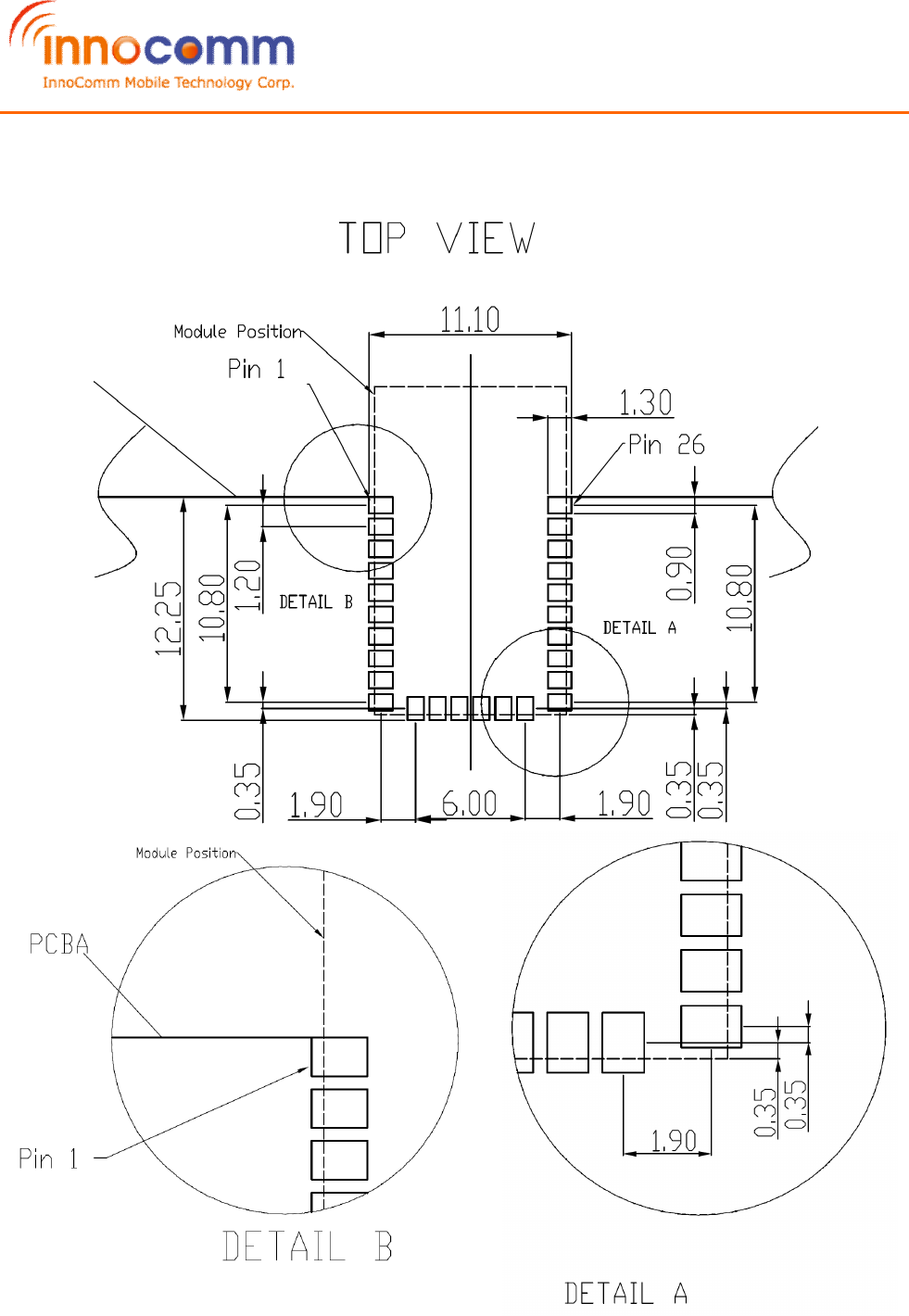
7. PCB Layout Recommendation
iCOM_BM15_AN R2 Module Product Specification
REV 1.4 9/26/2017
InnoComm Mobile Technology Confidential
14
/
19
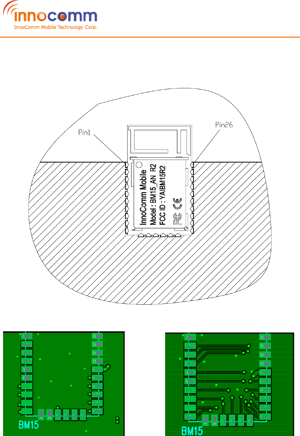
8. Module Placement Layout Guide
Placement Note: Please refer to “BM15_AN Module_Placement guideline v1.0.pdf”.
Layout Note: Do not route any trace under module to avoid interference.
(O) (X)
iCOM_BM15_AN R2 Module Product Specification
REV 1.4 9/26/2017
InnoComm Mobile Technology Confidential
15
/
19
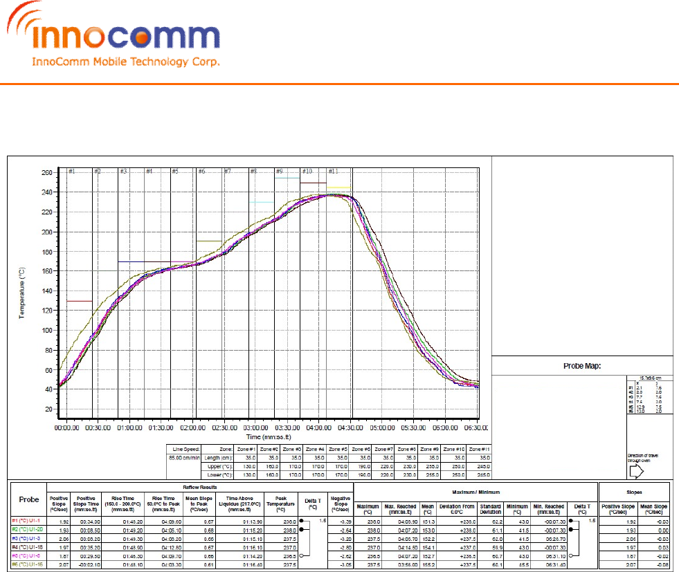
9. SMT Solder Reflow Recommendation
Note: Allowable reflow soldering times: 2 times base on recommended reflow
profile.

iCOM_BM15_AN R2 Module Product Specification
REV 1.4 9/26/2017
InnoComm Mobile Technology Confidential
16
/
19
10. Product and Documentation Support
10.1. Development Support
TI offers an extensive line of development tools, including tools to evaluate the performance of the
processors, generate code, develop algorithm implementations, and fully integrated and debug
software and hardware modules.
The following products support development of the CC2640 R2 device applications:
Software Tools:
SmartRF™ Studio 7 is a PC application that helps designers of radio systems to easily evaluate the
RF-IC at an early stage in the design process.
• Test functions for sending and receiving radio packets, continuous wave transmit and receive
• Evaluate RF performance on custom boards by wiring it to a supported evaluation board or
debugger
• Can also be used without any hardware, but then only to generate, edit and export radio
configuration settings
• Can be used in combination with several development kits for Texas Instruments’ CCxxxx RF-ICs
Sensor Controller Studio provides a development environment for the CC26xx Sensor Controller.
The Sensor Controller is a proprietary, power-optimized CPU in the CC26xx, which can perform
simple background tasks autonomously and independent of the System CPU state.
• Allows for Sensor Controller task algorithms to be implemented using a C-like programming
language
• Outputs a Sensor Controller Interface driver, which incorporates the generated Sensor Controller
machine code and associated definitions
• Allows for rapid development by using the integrated Sensor Controller task testing and debugging
functionality. This allows for live visualization of sensor data and algorithm verification.
IDEs and Compilers:
Code Composer Studio:
• Integrated development environment with project management tools and editor
• Code Composer Studio (CCS) 7.0 and later has built-in support for the CC26xx device family
• Best support for XDS debuggers; XDS100v3, XDS110 and XDS200
• High integration with TI-RTOS with support for TI-RTOS Object View
IAR Embedded Workbench for ARM
• Integrated development environment with project management tools and editor
• IAR EWARM 7.80.1 and later has built-in support for the CC26xx device family
• Broad debugger support, supporting XDS100v3, XDS200, IAR I-Jet and Segger J-Link
• Integrated development environment with project management tools and editor
• RTOS plug in available for TI-RTOS
For a complete listing of development-support tools for the CC2640 R2 platform, visit the Texas
Instruments website at www.ti.com. For information on pricing and availability, contact InnoComm
Mobile Technology Corporation sales office or authorized distributor.

iCOM_BM15_AN R2 Module Product Specification
REV 1.4 9/26/2017
InnoComm Mobile Technology Confidential
17
/
19
10.2. Documentation Support
To receive notification of documentation updates, navigate to the device product folder on ti.com
(CC2640R2F). In the upper right corner, click on Alert me to register and receive a weekly digest of any
product information that has changed. For change details, review the revision history included in any revised
document.
The current documentation that describes the CC2640R2F devices, related peripherals, and other technical
collateral is listed in the following.
Technical Reference Manual
SWCU117 Technical Reference Manual. Texas Instruments CC26xx Family of Products
10.3. Community Resources
The following links connect to TI community resources. Linked contents are provided "AS IS" by the
respective contributors. They do not constitute TI specifications and do not necessarily reflect TI's views; see
TI's Terms of Use.
TI E2E™ Online Community TI's Engineer-to-Engineer (E2E) Community. Created to foster
collaboration among engineers. At e2e.ti.com, you can ask questions, share knowledge, explore ideas and
help solve problems with fellow engineers.
TI Embedded Processors Wiki Texas Instruments Embedded Processors Wiki. Established to help
developers get started with Embedded Processors from Texas Instruments and to foster innovation and
growth of general knowledge about the hardware and software surrounding these devices.

iCOM_BM15_AN R2 Module Product Specification
REV 1.4 9/26/2017
InnoComm Mobile Technology Confidential
18
/
19
Federal Communication Commission Interference Statement
This device complies with Part 15 of the FCC Rules. Operation is subject to the following
two conditions: (1) This device may not cause harmful interference, and (2) this device must
accept any interference received, including interference that may cause undesired operation.
This equipment has been tested and found to comply with the limits for a Class B digital
device, pursuant to Part 15 of the FCC Rules. These limits are designed to provide
reasonable protection against harmful interference in a residential installation. This
equipment generates, uses and can radiate radio frequency energy and, if not installed and
used in accordance with the instructions, may cause harmful interference to radio
communications. However, there is no guarantee that interference will not occur in a
particular installation. If this equipment does cause harmful interference to radio or
television reception, which can be determined by turning the equipment off and on, the user
is encouraged to try to correct the interference by one of the following measures:
- Reorient or relocate the receiving antenna.
- Increase the separation between the equipment and receiver.
- Connect the equipment into an outlet on a circuit different from that
to which the receiver is connected.
- Consult the dealer or an experienced radio/TV technician for help.
FCC Caution: Any changes or modifications not expressly approved by the party
responsible for compliance could void the user's authority to operate this equipment.
This transmitter must not be co-located or operating in conjunction with any other antenna
or transmitter.

iCOM_BM15_AN R2 Module Product Specification
REV 1.4 9/26/2017
InnoComm Mobile Technology Confidential
19
/
19
Radiation Exposure Statement:
The product comply with the FCC portable RF exposure limit set forth for an uncontrolled
environment and are safe for intended operation as described in this manual. The further RF
exposure reduction can be achieved if the product can be kept as far as possible from the
user body or set the device to lower output power if such function is available.
This device is intended only for OEM integrators under the following conditions:
1) The transmitter module may not be co-located with any other transmitter or antenna.
As long as 1 conditions above are met, further transmitter test will not be required. However,
the OEM integrator is still responsible for testing their end-product for any additional
compliance requirements required with this module installed
IMPORTANT NOTE: In the event that these conditions can not be met (for example
certain laptop configurations or co-location with another transmitter), then the FCC
authorization is no longer considered valid and the FCC ID can not be used on the final
product. In these circumstances, the OEM integrator will be responsible for re-evaluating the
end product (including the transmitter) and obtaining a separate FCC authorization.
End Product Labeling
The product can be kept as far as possible from the user body or set the device to lower
output power if such function is available. The final end product must be labeled in a visible
area with the following: “Contains FCC ID: YAIBM15R2”. The grantee's FCC ID can be
used only when all FCC compliance requirements are met.
Manual Information To the End User
The OEM integrator has to be aware not to provide information to the end user regarding
how to install or remove this RF module in the user’s manual of the end product which
integrates this module.
The end user manual shall include all required regulatory information/warning as show in
this manual.