InnoComm Mobile Technology CM05 Wireless Module User Manual
InnoComm Mobile Technology Corporation Wireless Module
User Manual
CM05 WIFI/BLE Module
Product Specification
Model Name CM05
Project code
Description WIFI/BLE
Version 1.2
Issue Date 2018/05/31
Approved by Reviewed by Issued by
Taka Wei JH Huang Iestyn Chen

CM05 Product Specification
2018/10/31
REV1.2
Revision History
Revision Released Date Comments/Remark Author
0.1 2017/10/13 Initial release Iestyn Chen
0.2 2017/12/01 Add in HW performance data Iestyn Chen
0.3 2017/12/12 Modify the memory configuration of WiFi Iestyn Chen
1.0 2018/03/09 Modify the spec JH
1.1 2018/04/12 Modify the Mechanical information JH
1.2 2018/05/31 Modify the current consumption spec JH
® 2018 InnoComm Mobile Technology Corp.
GENERAL NOTICE
THE USE OF THE PRODUCT INCLUDING THE SOFTWARE AND DOCUMENTATION (THE "PRODUCT") IS SUBJECT TO THE
RELEASE NOTE PROVIDED TOGETHER WITH THE PRODUCT. IN ANY EVENT THE PROVISIONS OF THE RELEASE NOTE
SHALL PREVAIL. THIS DOCUMENT CONTAINS INFORMATION ABOUT INNOCOMM PRODUCTS. THE SPECIFICATIONS IN
THIS DOCUMENT ARE SUBJECT TO CHANGE AT INNOCOMM'S DISCRETION. INNOCOMM MOBILE TECHNOLOGY
GRANTS A NON-EXCLUSIVE RIGHT TO USE THE PRODUCT. THE RECIPIENT SHALL NOT TRANSFER, COPY, MODIFY,
TRANSLATE, REVERSE ENGINEER, CREATE DERIVATIVE WORKS; DISASSEMBLE OR DECOMPILE THE PRODUCT OR
OTHERWISE USE THE PRODUCT EXCEPT AS SPECIFICALLY AUTHORIZED. THE RECIPIENT UNDERTAKES FOR AN
UNLIMITED PERIOD OF TIME TO OBSERVE CONFIDENTIALLITY REGARDING ANY INFORMATION AND DATA PROVIDED
TO THEM IN THE CONTEXT OF THE DELIVERY OF THE PRODUCT. THIS GENERAL NOTE
SHALL BE GOVERNED AND CONSTRUED ACCORDING TO TAIWAN LAW.
Copyright
Transmittal, reproduction, dissemination and/or editing of this document as well as utilization of its contents and
communication thereof to others without express authorization are prohibited. Offenders will be held liable for
payment of damages. All rights created by patent grant or registration of a utility model or design patent are reserved.
Copyright © 2018, InnoComm Mobile Technology Corp.
Trademark Notice
InnoComm® is the trademarks of InnoComm Mobile Technology Corp.
Other trademarks and registered trademarks mentioned herein are the property of their respective owners.
2/15
InnoComm Mobile Technology

CM05 Product Specification
2018/10/31
REV1.2
3/15
InnoComm Mobile Technology
TABLE OF CONTENT
1. INTRODUCTION ......................................................................................... 4
2. KEY FEATURES ......................................................................................... 4
3. PIN MAP AND SIGNAL DESCRIPTION .................................................. 6
4. REFERENCE CIRCUIT ............................................................................... 7
5. ELECTRICAL CHARACETRISTICS ....................................................... 8
6. RF CHARACTERISTICS ............................................................................ 9
7. MECHANICAL INFORMATION .............................................................. 11
8..
RECOMMENDED PCB LAYOUT FOOTPRINT ...................................... 11
9.MODULE LAYOUT GUIDE .................................................................. 12
10. SMT SOLDER REFLOW RECOMMENDATION
.................................. 14
11.APPENDIX ............................................................................................. 15

CM05 Product Specification
2018/10/31
REV1.2
4/15
InnoComm Mobile Technology
1. Introduction
CM05 is a compact module that integrates both BLE and WiFi function, and an ARM Cortex-M4
MCU that runs customer’s application. The typical application of the module is bridging BLE sensor
clients to the cloud through WiFi router.
2. Key Features
■
BLE
•
BLE 5 connectivity
•
ARM Cortex-M4 32-bit processer with FPU
•
Memory
–
512kB Flash (chip internal)
–
64kB RAM (chip internal)
•
2.4GHz transceiver
–
95dBm sensitivity in Bluetooth low energy mode
•
1Mbps, 2Mbps supported data rate
•
TX power -20 to +4 dBm in 4 dB steps
•
Single-pin antenna interface
■
WIFI
•
ARM Cortex-M4 32-bit processer with FPU
•
Memory
–
512kB ROM (chip internal)
–
256kB RAM (chip internal)
–
2MB Flash (external)
•Radio
–
Single-pin antenna interface
–
2.4GHz
•Support of Standard
–
802.11b/g/n compatible WLAN
–
802.11e QoS Enhancement(WMM)
–
802.11i(WPA, WPA2). Open, shared key, and pair-wise key authentication services
–
WIFI Direct support
–
Light Weight TCP/IP protoco
CM05 Product Specification
2018/10/31
REV1.2
5/16
InnoComm Mobile Technology
3. PIN Map and Signal Description
Refer to Section 9 for pin location and arrangement.
Pin # Pin Name Description
1 GND Ground
2 GND Ground
3 BLE_ANT BLE Antenna
4 GND Ground
5 GPIO15 Digital
6 GPIO14 Digital
7 SWDIO BLE Debug/download
8 SWCLK BLE Debug/download
9 VDD Module Power in
10 n_RESET Reset, active Low, with internal pull–up
11 GPIO13 Digital/Trace port CLK
12 GPIO12 Digital
13 WIFI_DEBUG_EN WiFi Debug mode Enable
14 GND Ground
15 SWD_DATA WiFi Debug
16 SWD_CLK WiFi Debug
17 GND Ground
18 WIFI_ANT WiFi Antenna
19 GND Ground
20 WIFI_DEBUG_RX WiFi Log UART/download
21 WIFI_DEBUG_TX WiFi Log UART/download
22 GND Ground
23 GPIO10 Digital/Trace port
24 GPIO9 Digital/Trace port
25 GPIO8 Digital
26 GPIO7 Digital
27 GPIO6 Digital
28 GPIO5 Digital
29 GPIO11 Digital
30 GPIO4 Analog/Digital, SAADC/COMP/LPCOMP input
31 GPIO3 Analog/Digital, SAADC/COMP/LPCOMP input
32 GND Ground
33 GND Ground
34 GPIO1 Analog/Digital, SAADC/COMP/LPCOMP input
35 GPIO2 Analog/Digital, SAADC/COMP/LPCOMP input
36 GPIO22 Analog/Digital, SAADC/COMP/LPCOMP input
37 GPIO21 Analog/Digital, SAADC/COMP/LPCOMP input
CM05 Product Specification
2018/10/31
REV1.2
6/15
InnoComm Mobile Technology
Pin # Pin Name Description
38 GPIO20 Analog/Digital, SAADC/COMP/LPCOMP input
39 GPIO19 Analog/Digital, SAADC/COMP/LPCOMP input
40 GPIO18 Digital
41 GPIO17 Digital
42 GPIO16 Digital
43 GND Ground
F1 NC
F2 NC
F3 NC
F4 NC
F5 NC
F6 NC
CM05 Product Specification
2018/10/31
REV1.2
7/15
InnoComm Mobile Technology
4. ELECTRICAL CHARACETRISTICS
4.1
Recommended Operating Range
PARAMETER MIN TYP MAX UNIT
Operating temperature range –20 25 85 °C
Operating supply voltage 3 3.3 3.6 V
4.2
Power Consumption
PARAMETER MIN TYP MAX UNIT
WIFI 11n TX supply current at
maximum output power 280 mA
WIFI 11g TX supply current at
maximum output power 280 mA
WIFI 11b TX supply current at
maximum output power 350 mA
WIFI RX supply current 130 mA
BLE TX supply current at maximum
output power(+4dBm) 25 mA
BLE RX 16 mA
System off mode 10 uA
Detail to be added
4.3
GPIO Characterization information
PARAMETER MIN TYP MAX UNIT
Voltage at digital I/O pins -0.3 VDD + 0.3 V
Input Low voltage level(VIL) 0.3xVDD V
Input High voltage level(VIH) 0.7xVDD VDD V
Output Low Voltage level(VOL) 0.4 V
Output Low Voltage level(VOH) VDD-0.4 VDD V
28
26
28
20.5
otherwise
CM05 Product Specification
2018/10/31
REV1.2
8/15
InnoComm Mobile Technology
5. RF Characteristics
5.1
BLE TX Characteristics
Following characteristics are valid for conditions as follows (unless otherwise specified)
Tamb = -20 °C to 85 °C, VCC = 3.3 V
Bursts: 10, Payload: PRBS 9, Length: 37 Bytes
PARAMETER
MIN TYP
MAX UNIT
Maximum TX Power
4
dBm
1st Adjacent Channel Transmit Power 1 MHz (1
Msps)
-25
dBc
2nd Adjacent Channel Transmit Power 2 MHz (1
Msps)
-50
dBc
1st Adjacent Channel Transmit Power 2 MHz (2
Msps)
-25
dBc
2nd Adjacent Channel Transmit Power 4 MHz (2
Msps)
-50
dBc
5.2
BLE RX Characteristics
Following characteristics are valid for conditions as follows (unless otherwise specified)
Tamb = -20 °C to 85 °C, VCC = 3.3 V, Payload: PRBS 9, Length: 37
PARAMETER
MIN TYP
MAX UNIT
Receiver Sensitivity -95 dBm
5.3
WIFI TX Characteristics
Following characteristics are valid for conditions as follows (unless specified
Tamb = -20 °C to 85 °C, VCC = 3.3 V
PARAMETER
MIN TYP
MAX UNIT
Maximum TX Power 802.11G 54MHz dBm
Maximum TX Power 802.11B 11MHz dBm
Maximum TX Power 802.11N HT20 dBm
Maximum TX Power 802.11N HT40 dBm
CM05 Product Specification
2018/10/31
REV1.2
9/15
InnoComm Mobile Technology
Following characteristics are valid for conditions as follows (unless otherwise specified
Tamb = -20 °C to 85 °C, VCC = 3.3 V
PARAMETER
MIN TYP
MAX UNIT
EVM 802.11G 54MHz
-30
dB
EVM 802.11B 11MHz
-24.5
dB
EVM 802.11N HT20
-31
dB
EVM 802.11N HT40
-31
dB
5.4
WIFI RX Characteristics
Following characteristics are valid for conditions as follows (unless otherwise specified
Tamb = -20 °C to 85 °C, VCC = 3.3 V
PARAMETER
MIN TYP
MAX UNIT
Sensitivity 802.11G 54MHz -79 dBm
Sensitivity 802.11B 11MHz -89 dBm
Sensitivity 802.11N HT20 -73 dBm
Sensitivity 802.11N HT40 -70 dBm
CM05 Product Specification
2018/10/31
REV1.2
10/15
InnoComm Mobile Technology
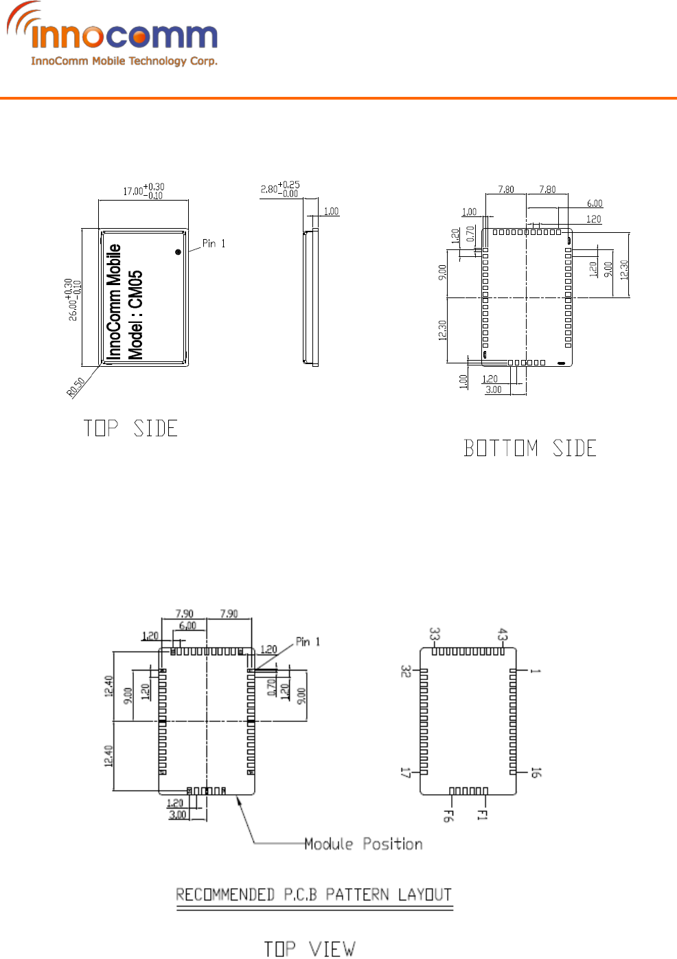
6. Mechanical Information
7. Recommended PCB Layout Footprint
CM05 Product Specification
2018/10/31
REV1.2
11/15
InnoComm Mobile Technology
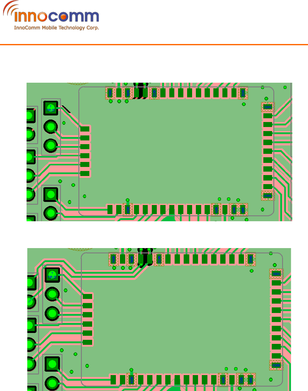
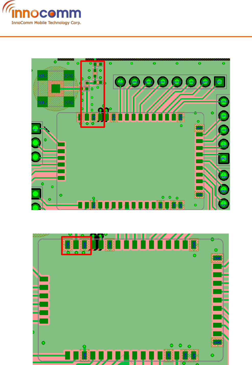
8. Module Layout Guide
I. Do not route traces under module to minimize on interference.
(O)
(X)
CM05 Product Specification
2018/10/31
REV1.2
12/15
InnoComm Mobile Technology
II. The trace Impedance of the antenna port (Pin 18) is 50 Ω. In order to minimize the return
loss, it is recommended to use short traces.
III. Keep enough clearance between the antenna port (Pin 18) and surrounding GND to
minimize the power loss.
(O)
CM05 Product Specification
2018/10/31
REV1.2
13/15
InnoComm Mobile Technology
(X)
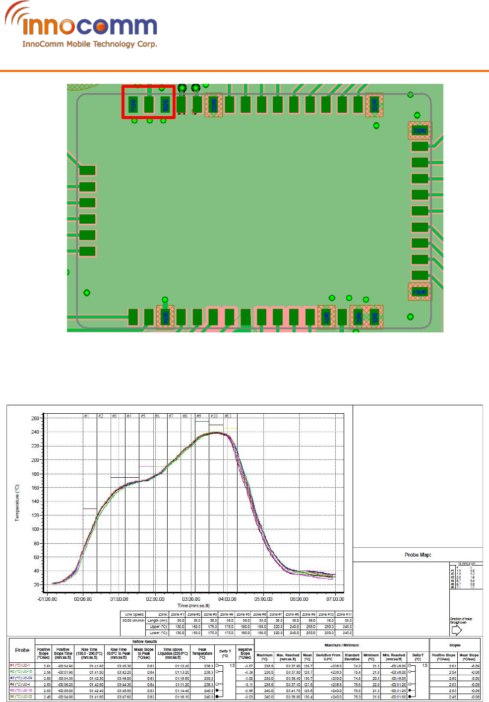
9. SMT Solder Reflow Recommendation
Note: Allowable reflow soldering times: 2 times base on recommended reflow profile.
CM05 Product Specification
2018/10/31
REV1.2
14/15
InnoComm Mobile Technology
10. Appendix
IO Mapping
BLE CM05 Module Pin Assignment WIFI
Pin Number Pin Name Type Pin Number Pin name Pin name
4 P0.02
Analog/Digital 34 GPIO1
5 P0.03
Analog/Digital 35 GPIO2
6 P0.04
Analog/Digital 31 GPIO3
7 P0.05
Analog/Digital 30 GPIO4
8 P0.06
Digital 29 GPIO11
9 P0.07
Digital 28 GPIO5
10 P0.08
Digital 27 GPIO6
11 P0.09
NFC/Digital 26 GPIO7
12 P0.10
NFC/Digital 25 GPIO8
14 P0.11 Digital GPIOA23
UART0_TXD
15 P0.12 Digital GPIOA22
UART0_RTS
16 P0.13 Digital GPIOA19
UART0_CTS
17 P0.14
Digital/Trace port 24 GPIO9
18 P0.15
Digital/Trace port 23 GPIO10
19 P0.16
Digital/Trace port WIFI_EN
20 P0.17 Digital GPIOA18
UART0_RXD
21 P0.18
Digital/Trace port GPIOA_5
22 P0.19
Digital 12 GPIO12
23 P0.20
Digital/Trace port CLK 11 GPIO13
24 P0.21
Digital/Reset 10 nReset
27 P0.22
Digital GPIOA_12
28 P0.23
Digital 6 GPIO14
29 P0.24
Digital 5 GPIO15
37 P0.25
Digital 42 GPIO16
38 P0.26
Digital 41 GPIO17
39 P0.27
Digital 40 GPIO18
40 P0.28
Analog/Digital 39 GPIO19
41 P0.29
Analog/Digital 38 GPIO20
42 P0.30
Analog/Digital 37 GPIO21
43 P0.31
Analog/Digital 36 GPIO22

15/15
InnoComm Mobile Technology
CM05 Product Specification
2018/10/31
REV1.2
Federal Communications Commission Statement
This device complies with FCC Rules Part 15. Operation is subject to the following two conditions:
•This device may not cause harmful interference.
•This device must accept any interference received, including interference that may cause undesired
operation.
This equipment has been tested and found to comply with the limits for a class B digital device, pursuant to
Part 15 of the Federal Communications Commission (FCC) rules. These limits are designed to provide
reasonable protection against harmful interference in a residential installation. This equipment generates,
uses, and can radiate radio frequency energy and, if not installed and used in accordance with the
instructions, may cause harmful interference to radio communications. However, there is no guarantee that
interference will not occur in a particular installation. If this equipment causes harmful interference to radio
or television reception, which can be determined by turning the equipment off and on, the user is
encouraged to try to correct the interference by doing one or more of the following measures:
•Reorient or relocate the receiving antenna.
•Increase the separation between the equipment and receiver.
•Connect the equipment into an outlet on a circuit different from that to which the receiver is
connected.
•Consult the dealer or an experienced radio/TV technician for help.
FCC Caution
Any changes or modifications not expressly approved by the party responsible for compliance could void
the user‘s authority to operate the equipment.
The antenna(s) used for this transmitter must not be co-located or operating in conjunction with any other
antenna or transmitter.
Radiation Exposure Statement:
This equipment complies with FCC radiation exposure limits set forth for an uncontrolled environment. End
users must follow the specific operating instructions for satisfying RF exposure compliance. To maintain
compliance with FCC exposure compliance requirement, please follow operation instruction as documented
in this manual.
This equipment must be installed and operated in accordance with provided instructions and the
antenna(s) used for this transmitter must be installed to provide a separation distance of at least 20 cm
from all persons and must not be co-located or operating in conjunction with any other antenna or
transmitter.
FCC Label Instructions:
The outside of final products that contains this module device must display a label
referring to the enclosed module. This exterior label can use wording such as: “Contains
Transmitter Module FCC ID:YAICM05”,or “Contains FCC ID: YAICM05”, Any similar wording that expresses
the same meaning may be used.