InnoComm Mobile Technology WM05-AN WiFi Module User Manual
InnoComm Mobile Technology Corporation WiFi Module
UserManual.wiki
>
InnoComm Mobile Technology
>
WM05 AN User Manual
User Manual.pdf
Navigation menu
Upload a User Manual
Namespaces
Wiki Guide
HTML
PDF
Info
Views
User Manual
Discussion / Help
Navigation
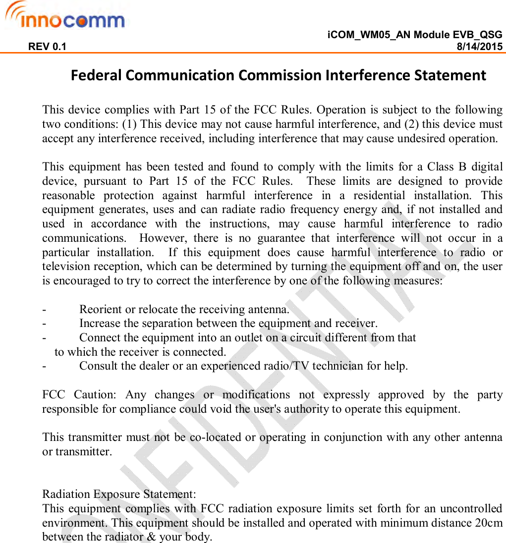
![iCOM_WM05_AN Module EVB_QSG REV 0.1 8/14/2015 [General Information] The WM05_AN Evaluation Module Kit contains two WM05_AN (TI CC3200) modules supported USB to UART interface which is prepared for WiFi performance testing purpose. WM05_AN module provides excellent low power consumption with astonishing wireless connection range. Part Number WM05_AN Photo Description WiFi module Size (mm) 20.5x24x2.3 Pin count 63 Mounting Method SMD Supply Voltage 2.5V ~ 3.6V I/O GPIO x23 Wifi connect to UART Interface Your package contains 1. WM05_AN EVB 2. 2 x software: USB driver & PC tool for performance test](https://usermanual.wiki/InnoComm-Mobile-Technology/WM05-AN/User-Guide-2722284-Page-2.png)
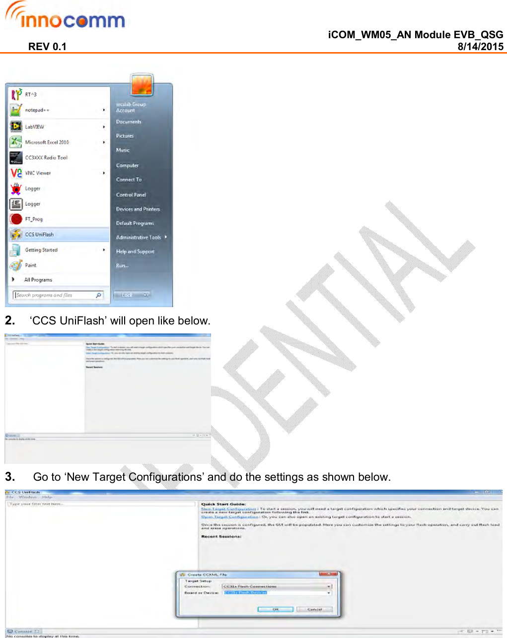
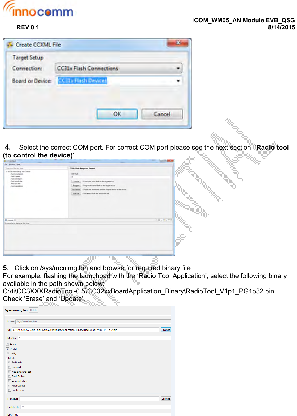
![iCOM_WM05_AN Module EVB_QSG REV 0.1 8/14/2015 EVB Drive FTDI2232D Uniflash: http://www.ti.com/tool/uniflash Radio Tool: http://www.ti.com/tool/cc3xxxradiotest [EVB] Uniflash (to flash applications): 1. Please make sure programmer jumper is closed. Once Uniflash is installed (uniflash_cc3xxx_setup_3.2.0.00019.exe), invoke ‘CCS UniFlash’.](https://usermanual.wiki/InnoComm-Mobile-Technology/WM05-AN/User-Guide-2722284-Page-3.png)
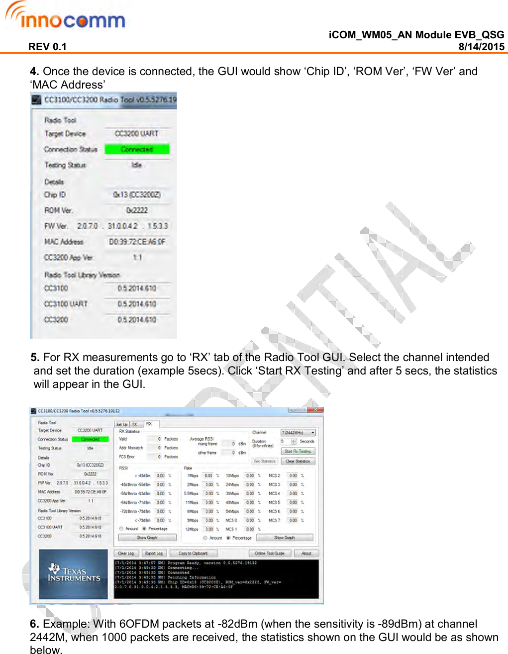
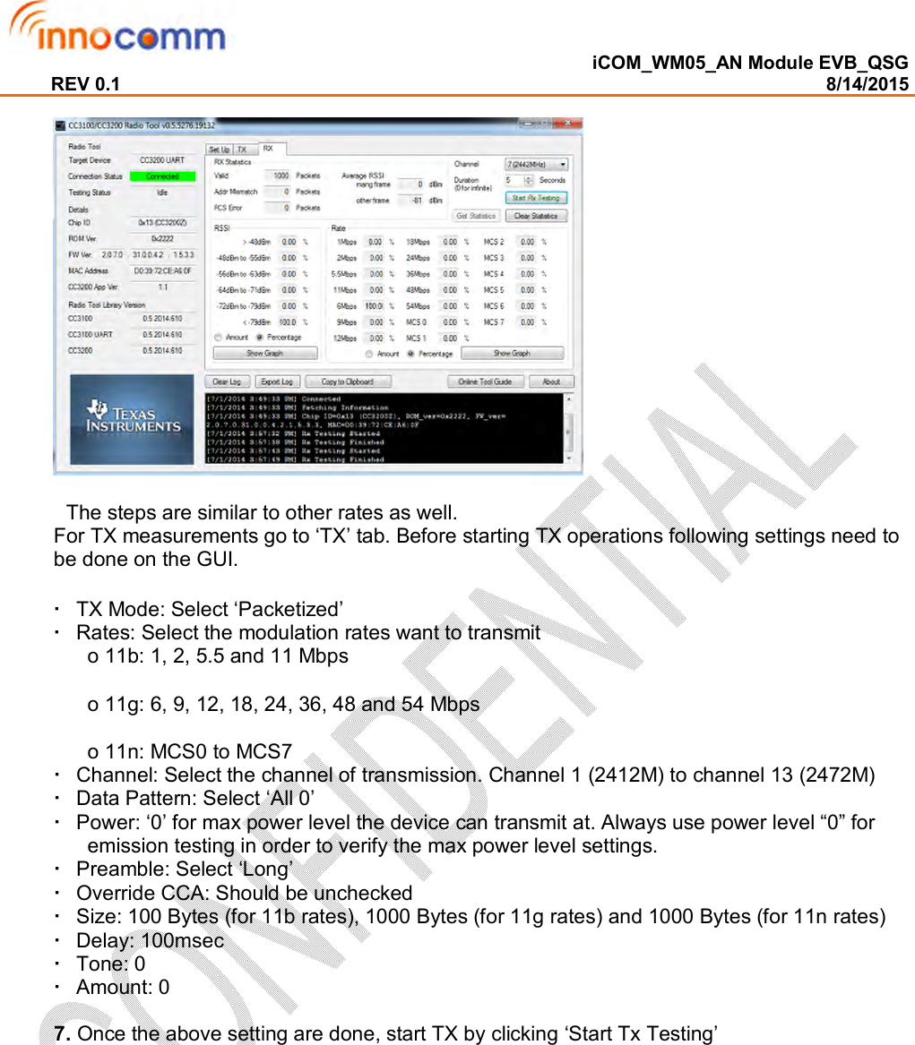
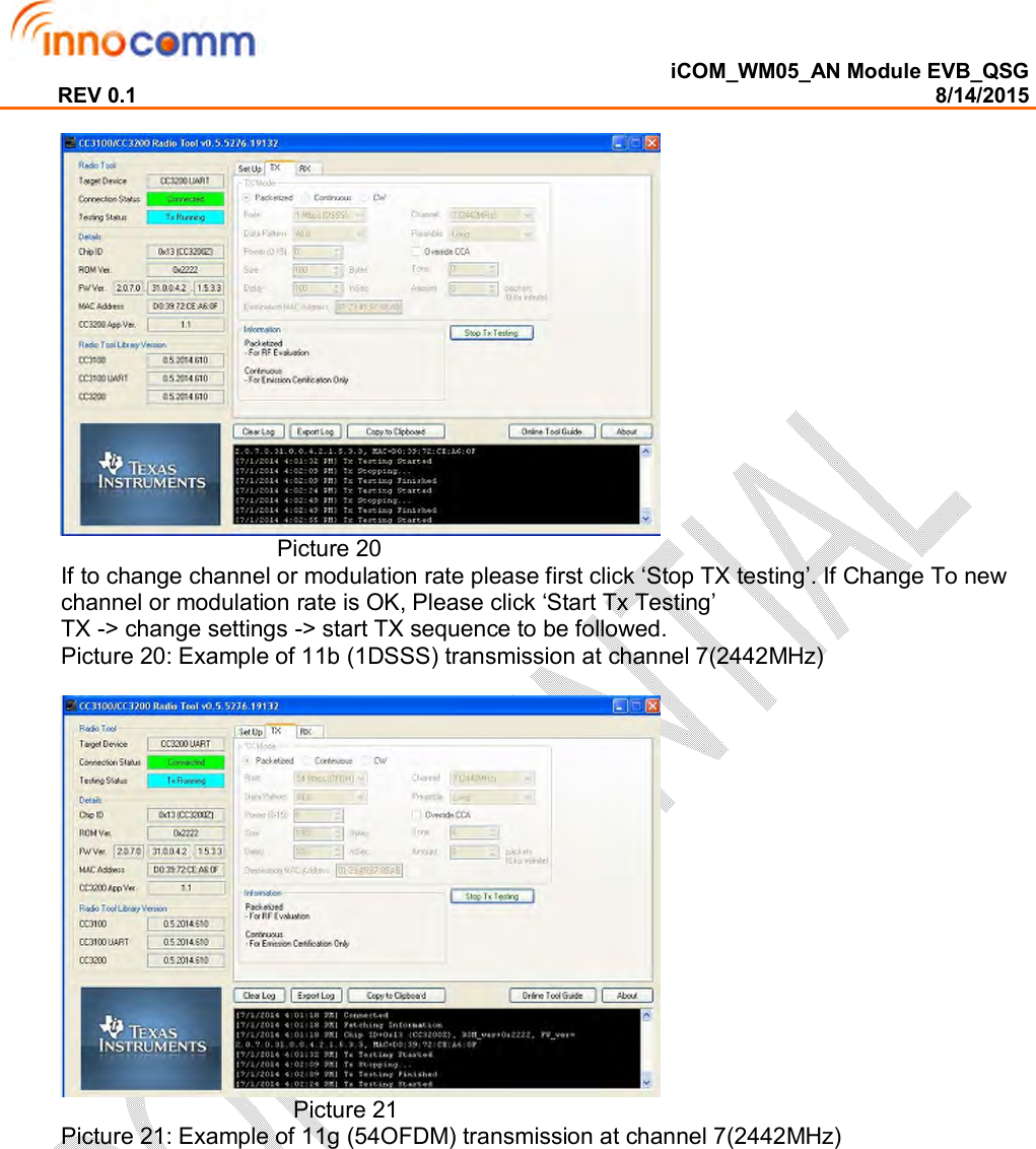
![iCOM_WM05_AN Module EVB_QSG REV 0.1 8/14/2015 Picture 22 Picture 22: Example of 11n (MCS7) transmission at channel 7(2442MHz) [Software application development] Development support The CC3200 includes a set of tools and documentation to help the user during the development phase. PinMux Tool: The CC3200 device uses pin multiplexing extensively to accommodate the large number of peripheral functions in the smallest possible package. The PinMux tool is a utility used to select the appropriate pin multiplexing configuration that meets the end application requirements. The PinMux tool makes it easy to understand the various pin multiplexing options and enables the best configuration to be chosen without error. Radio Tool: The SimpleLink radio tool is a utility for operating and testing the CC3200 chipset designs during development of the application board. The CC3200 device has an auto-calibrated radio that enables easy connection to the antenna without requiring expertise in radio circuit design. Uniflash Flash Programmer: The Uniflash flash programmer utility allows end users to communicate with the SimpleLink device to update the serial flash. The easy GUI interface enables flashing of files (including read-back verification option), storage format (secured and nonsecured formatting), version reading for boot loader and chip ID, and so on. Supported profiles & sample applications 1. Cloud Connectivity 2. Home Automation 3. Home Appliances 4. Access Control 5. Security Systems 6. Smart Energy 7. Internet Gateway 8. Industrial Control 9. Smart Plug and Metering 10. Wireless Audio 11. IP Network Sensor Nodes](https://usermanual.wiki/InnoComm-Mobile-Technology/WM05-AN/User-Guide-2722284-Page-11.png)