InnoLabs I1000-PII Personal Computing Tablet User Manual ch2
InnoLabs Corporation Personal Computing Tablet ch2
InnoLabs >
Ch2

Operating Basics
This chapter gives detailed information on system components. If you
are a novice user, this chapter helps you better understand the operation
of the computer. If you are an advanced user, simply refer to a relevant
section when you need specific information.

2-2 Operating Basics
2
Indicator Panel/Features and Controls
On the Qbe controls and indicators have been reduced to a
minimum for simplicity of use.
These are placed at the top end, the rear, right and left
sides of the Qbe:
• two LED indicators for battery and hard disk status.
• built in microphone
• 270K Pixel Color CCD. Higher resolution might be
available.
• scroll up and down button
• a right mouse click/snap button.
• A CD-ROM or swappable DVD slot and CD RW
• speakers situated on the right and left hand side of the
unit
• FIR on the right hand side of the PCT
• Rubber feet and protection.
A modular bay (ICM Port - Image Capture Module) exists for
• optional cameras
• barcode scanners and other image capture peripherals
perating Basics 2-3
2
There is an optional IC Card Reader (Smartcard - Read/Write)
and Magnetic Strip Reader.
(diagram)
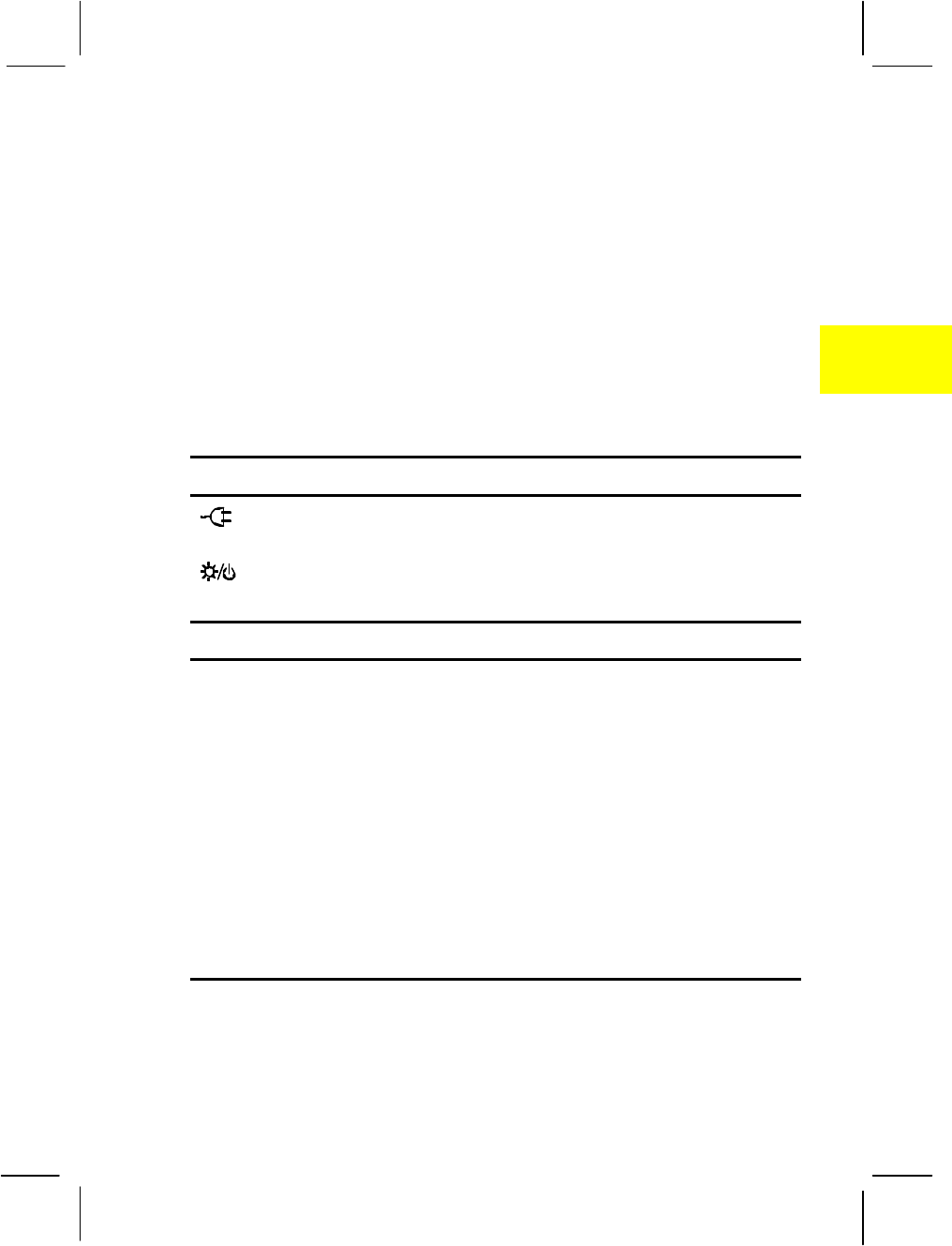
Indicator Panel
Descriptions of the indicators:
LED
AC Power Indicator lights green when the AC adapter is
connected to the computer and an electrical outlet.
Hard Disk Indicator flashes green when the hard disk is in
operation.
LCD
2-4 Operating Basics
2
Keyboard
Your USB keyboard which comes bundled with the Qbe has all the
functions of a standard AT-enhanced keyboard.
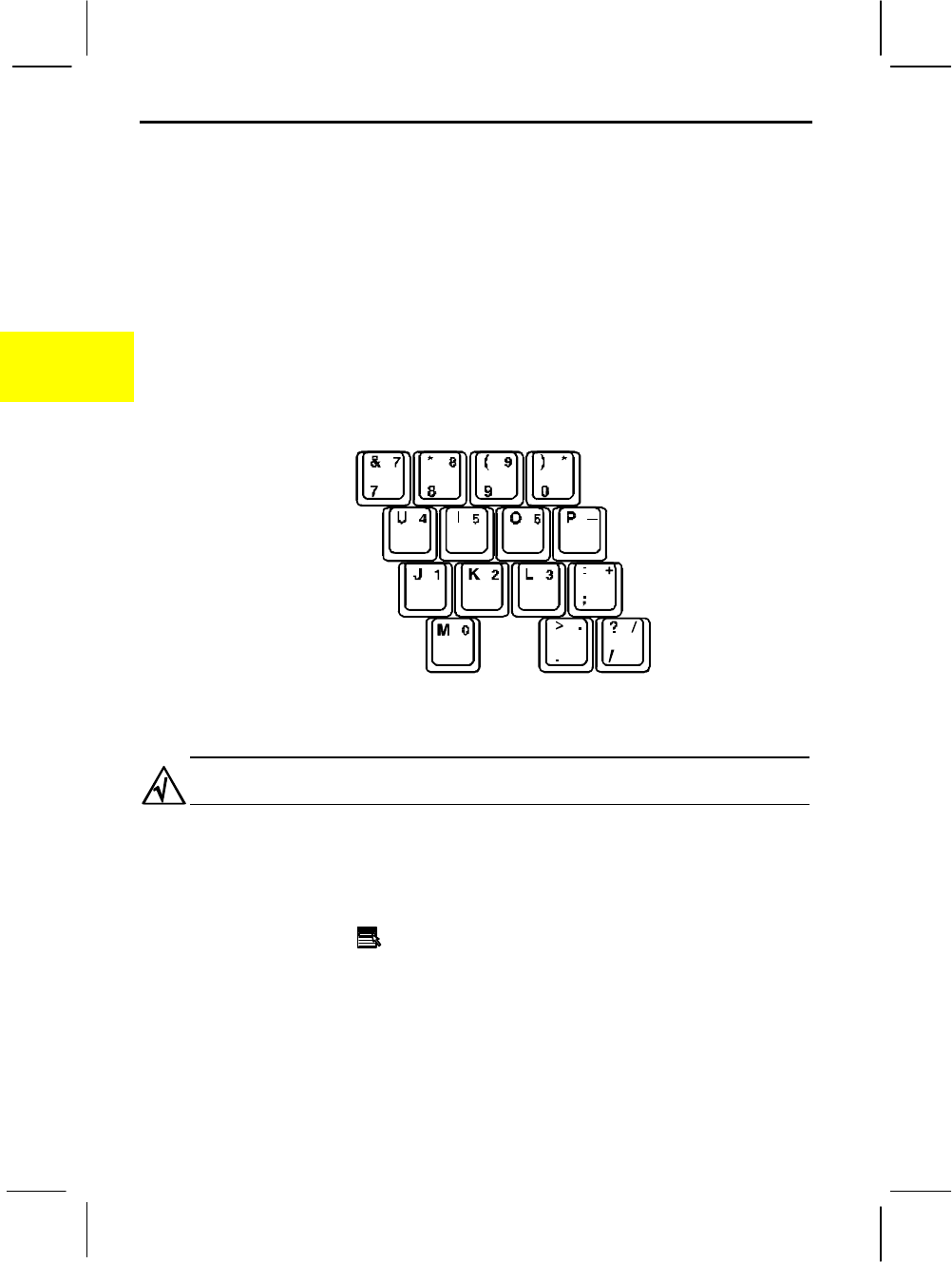
Numeric Keypad
The numeric keypad is embedded in the keyboard as shown below.
When Num Lock is on, these numeric keys take effect.
Figure 2-2. Numeric Keypad
If you want Num Lock to be automatically activated after the computer is
turned on, enable the “Keyboard Numlock” item in the SCU program.
Windows 95 Keys
A Windows 95 keyboard has a Windows Logo ( ÿ ) key and an
Application Logo ( ) key. Each key is used in combination with other
keys to perform software-defined functions.

perating Basics 2-5
2
Touch Screen Control
Silicon Motion Control Programs (SMI)
Calibration
Before going to work on the PCT you’ll need to calibrate the Touchscreen.
Calibration defines the active area of the touchscreen and aligns the active
area with the underlying video.
You will need to carry out this procedure whenever you
• Initially install TouchWare
• Change the Video Resolution
• Adjust the horizontal or vertical controls
• Run the Stabilize Cursor function
• Notice the cursor does not follow the movement of yourfinger or pen or
does not reach the edge of the touchscreen.
It is a relatively simple procedure, using either the digital pointer/pen
provided or simply your finger.

2-6 Operating Basics
2
1. In the MicroTouchscreen Properties Window, apply the pen tip or
your finger lightly to the word Calibration in the rectangular box:
Touch Pen or Finger Only depending on preference.
2 Apply the pen or finger tip to the four “target areas” at the corners of the
screen in either a clockwise or anti-clockwise direction.
3. After this, apply the pen or your finger tip to the small target area at
the center of the screen.
4. Click DONE.
Make sure that you do not touch the screen while calibration is
in process.
Transfer Mode:
Click on the SMI icon in the lower right hand corner.
A Window pops up – SMI Display Properties.
Rotation Off/OK
Rotation Recalibrate

perating Basics 2-7
2
Screen Rotation/ Vertical/Landscape
Touch Screen control and screen rotation from Vertical or Landscape
are distinct advantages with the QBE.
These functions and features open a whole range of applications and
possibilities in a number of disciplines, from distance learning to stock
taking.
To change the screen format click on the MicroTouch icon on your
Desktop. This opens the Display Properties Window of the SMI.
Silicon Motion Control Programs (SMI)
(graphic)
: Make sure the Display Switching commands for the LCD
and CRT are in the ON mode.
:That the TV setting is in OFF mode and that you have selected to
either the NTSC or PAL standards depending on your equipment and
location.
2-8 Operating Basics
2
In Special Modes, toggle to the OFF button, Rotation should be ON
and ENABLE the Hot Key.
diagram
Figure 2-3. Using the Pointing Device
Term Action
Point Slide your fingertip so that the pointer points to the
selection on the screen.
Click Press and release the button at top right hand corner of
top of the Qbe
Double-click Press and release the button (usually left button) twice
in quick succession.
*An alternative and faster way of pressing the left
button twice is to tap your fingertip twice in quick
succession.
Drag and drop Press and hold the button (usually left button), then
move your fingertip. When you finish dragging your
selection to its new location, release the button.
*You can also perform drag-and-drop using the
touchpad as a large left button. Position the cursor
over the item that you want to drag. Gently tap twice
on the pad. On the second tap, keep your fingertip in
contact with the pad and slide your fingertip across the
pad to drag the selected object to the destination. Then,
lift your fingertip from the pad and the selected object
will drop into place.
* Table Note: If you swap the left and right buttons, “Tapping” on the
pad as an alternative way of pressing the left button will be invalid
If the touchpad seems to become less sensitive, cleaning the pad may solve the
problem. Clean by using adhesive tape to remove the dust and grease on the

perating Basics 2-9
2
pad surface.
2-10 Operating Basics
2
Hard Disk Drive
Your Qbe has a 2.5-inch IDE (Integrated Drive Electronics) hard disk
drive − Drive C.
A hard disk drive contains non-removable magnetic platters. When
compared with a diskette, it can read and write data much faster and has
a much larger storage capacity.
1. Regularly back up your data files from the hard disk drive to diskettes.
2. Never turn off or reset the computer when the hard disk drive indicator is
on.
3. Never try to remove or install the hard disk drive while the system power
is on. Doing so can result in loss of data, and can damage the system and
the hard disk drive.
Removing the Hard Disk Drive
The hard disk drive is packaged in a module so that you can easily
remove it. For safety reasons, you may want to temporarily remove the
hard disk drive and store it in a safe place after you finish using the
computer.
Follow this procedure to remove and replace the hard disk drive module.
1. Make sure the computer is turned off.
2. Open the hard disk drive compartment at the bottom of the PCT.
3. Pull the handle to slide the hard disk drive out of the compartment.
(diagram)
Figure 2-5. Removing the Hard Disk Drive Module

perating Basics 2-11
2
4. To replace the hard disk drive, slide the hard disk drive back into the
compartment.
5. Close the compartment cover.
2-12 Operating Basics
2
CD-ROM Drive
Your Qbe has a CD-ROM drive, usually configured as drive D.
A CD-ROM drive uses removable 5.25-inch silver CD-ROM disks,
which look like standard music CDs. A CD-ROM disk is an ideal
medium to use for distributing multimedia software because of its large
storage capacity (up to 600MB).
Inserting and Removing a CD
1. When inserting a CD, do not use force.
2. Make sure the CD is correctly inserted into the tray, then close the tray.
3. Do not leave the CD tray open. Also, avoid touching the lens in the tray
with your hand. If the lens becomes dirty, the CD-ROM may malfunction.
4. Do not wipe the lens with materials with rough surface (such as paper
towel). Instead, use a cotton swab to gently wipe the lens.
FDA regulations require the following statement for all laser-based devices:
Caution, Use of controls or adjustments or performance of procedures other
than those specified herein may result in hazardous radiation exposure.”
Follow this procedure to insert or remove a CD.
1. Turn on the computer.
2. Press the eject button and the CD tray will slide out. If the tray only
partially slides out, then gently pull it out completely.
3. To insert a CD, hold it with the label facing up and then place it on
the tray.
Depending on your CD-ROM drive model, the front panel of your CD-ROM
drive may look slightly different from the one shown below.
(diagram)

perating Basics 2-13
2
Figure 2-6. Inserting a CD
To remove a CD, hold the CD by its outer edge and lift it from the
tray.
4. Slide the tray back into the drive bay. On some models, you can
press the eject button to slide back the tray.
Manually Releasing a CD
Though unlikely, if you are unable to release the CD tray by pressing the
eject button, you can manually release the CD using the following
method:
1. Turn off the system.
2. Insert a small pointed device into the manual eject hole (see Figure 2-
6) and push firmly to release the tray.
3. Pull the tray out completely, then remove the CD.

2-14 Operating Basics
2
LCD Display
You can select the resolution and the number of colors using the video
drivers. The resolutions and colors supported by your LCD are:
Resolution Number of Colors
640 x 480 256
64K
16M
800 x 600 256
64K
16M
1024 x 768 256
64K
16M
Power Management is implemented in the LCD in the following ways:
• The screen goes blank when no activity has taken place within a
given period of time. The screen image returns when any activity is
detected.
• When you close the LCD display,
• If an external monitor is not connected, the computer will enter
Power-On-Suspend mode. When you next open the LCD
display, the computer will resume.
• If an external monitor is connected, the display output is switched
to the monitor. When you next open the LCD display, you can
switch the display output back by pressing [Fn]+[F4].

perating Basics 2-15
2
Networking
Your Qbe incorporates the 10/100 Base-T LAN (Local Area Network)
capabilities to make it ready for connection to a network environment
using Ethernet protocol.
Connecting the Network Cable
1. Turn off the computer.
2. The RJ-45 connector at the rear of the PCT can be connected to a
type 1 STP or category 5 UTP cable.
graphic. Connecting the Network Cable
3. Turn on the computer.
Enabling/Disabling the LAN Connection
If your PCT is connected to LAN, there will be 5 to 20 seconds time lag
before Windows starts to work when resuming from suspend mode. The
time-delay is spent by Windows to check and “Wake up” all hardware
and re-connect the network when resuming from low power mode. If
you want to minimize the time lag, you can disable the LAN connection
since the LAN function can be disabled or enabled easily and
dynamically in Windows. The following description shows the
procedures for disabling or enabling LAN through Windows.
1. Click “Start”, “Setting”, and then “Control Panel”.
2. Double click the “System” icon.
3. Click “Device Manager”.

2-16 Operating Basics
2
4. Double click “Network Adapter”.
5. Select “General”.
6. Select “Disable in this hardware profile” in “Device Usage” dialog
to disable LAN, or not to select “Disable in this hardware profile” to
enable LAN.
7. Restart the computer.

perating Basics 2-17
2
PC Cards
PC cards, sized like credit cards, are inserted into the PC card slots to
provide specific functions such as memory, fax/modem, networking, and
PCMCIA Type III 1.8-inch hard disk drive.
PC cards that conform to the PCMCIA 2.1/3.0 standard can be used
with your Qbe. Two advanced interfaces are also supported: CardBus
and ZV (Zoomed Video) port. CardBus and ZV port standards are
developed to provide high-speed data transmission required by
applications such as full-motion video, video capture, and networking.
Inserting and Removing a PC Card
1. Locate the PC card slots at the rear left side of the PCT. Remove
the “dummy” card(s) by depressing either one of the two buttons.
The upper slot is Slot 0 and the lower Slot 1.
2. To insert a PC card, with the label facing up, slide it into the
appropriate slot until the eject button pops out.
(graphic)
Figure 2-8. Installing a PC Card
To remove a PC card, press the corresponding eject button. The
card will pop out partially. Slide out the card and store it properly.
3. See the documentation supplied with your PC card for further
instructions.

2-18 Operating Basics
2
Modem Communications
This PCT is equipped with the Mini PCI Type IIIA NIC/Modem Combo
Card. The latter is a 56Kbps V.90 and K56flex dual mode for fast
Internet surfing.
There is integrated IEEE 802.3 10BASE-T and 100BASE-TX
compatible PHY Glueless 32-bit PCI master interface.
Connecting to Phone Line
1. Turn off the Qbe.
2. Access the RJ-11 port at the rear right hand side of the Qbe.
Connect either end of the phone cable to the RJ-11 modem
connector and the other end to the wall jack.
(graphic)
Figure 2-9. Connecting the Phone Cable
3. Turn on the computer.

perating Basics 2-19
2