Innokas Yhtyma VC150 Patient Monitor User Manual
Innokas Yhtyma Oy Patient Monitor
UserManual.wiki
>
Innokas Yhtyma
>
VC150 User Manual
Operators Manual
Navigation menu
Upload a User Manual
Namespaces
Wiki Guide
HTML
PDF
Info
Views
User Manual
Discussion / Help
Navigation
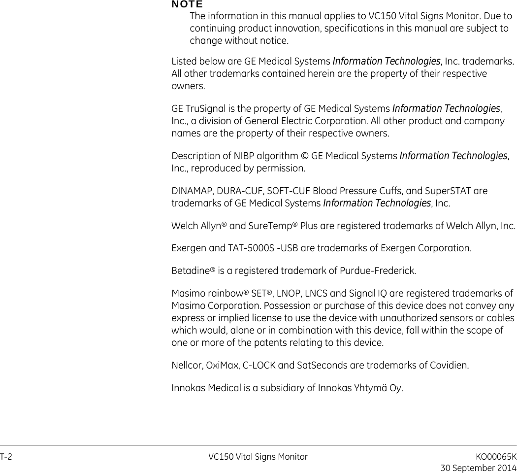
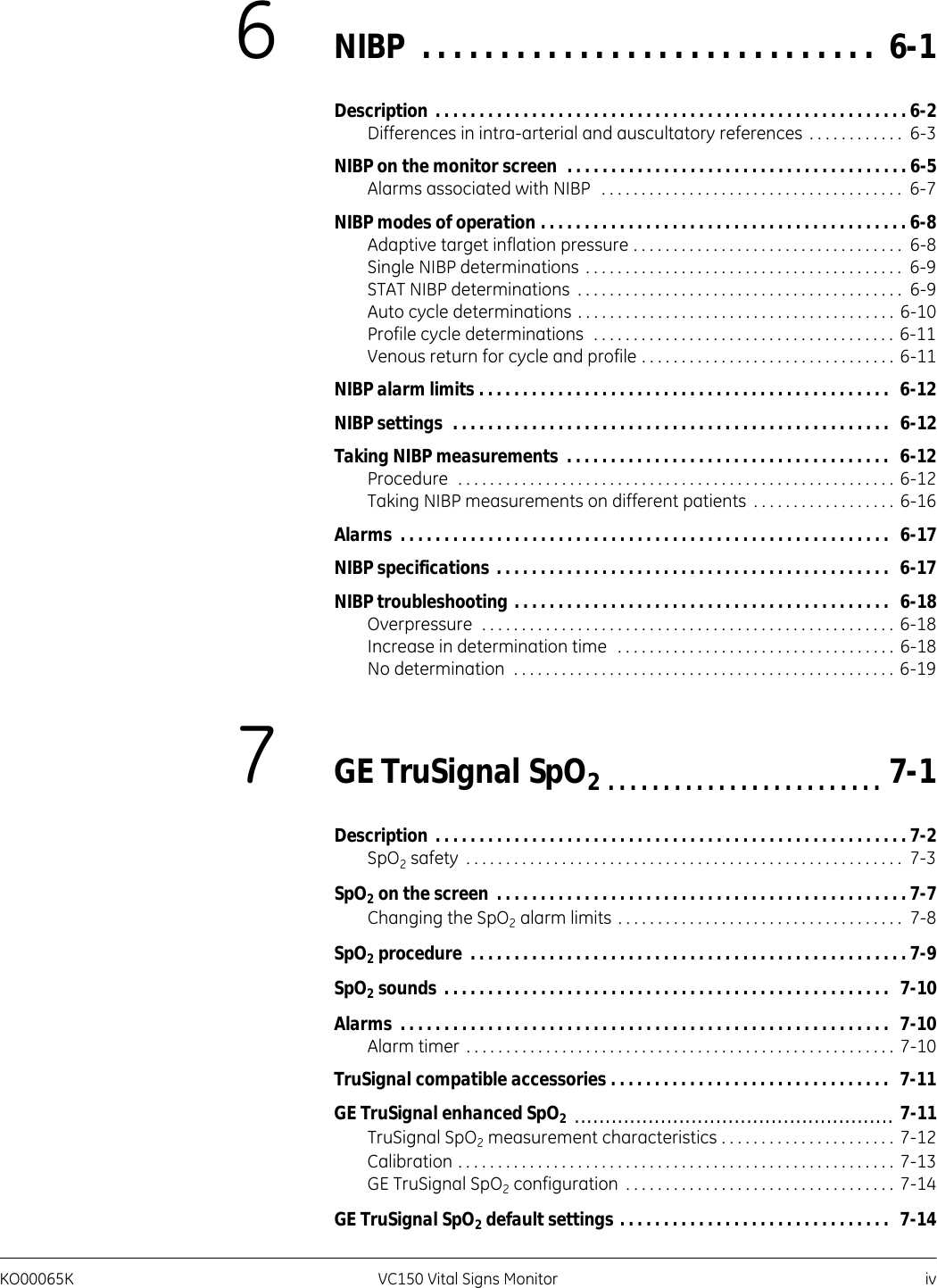
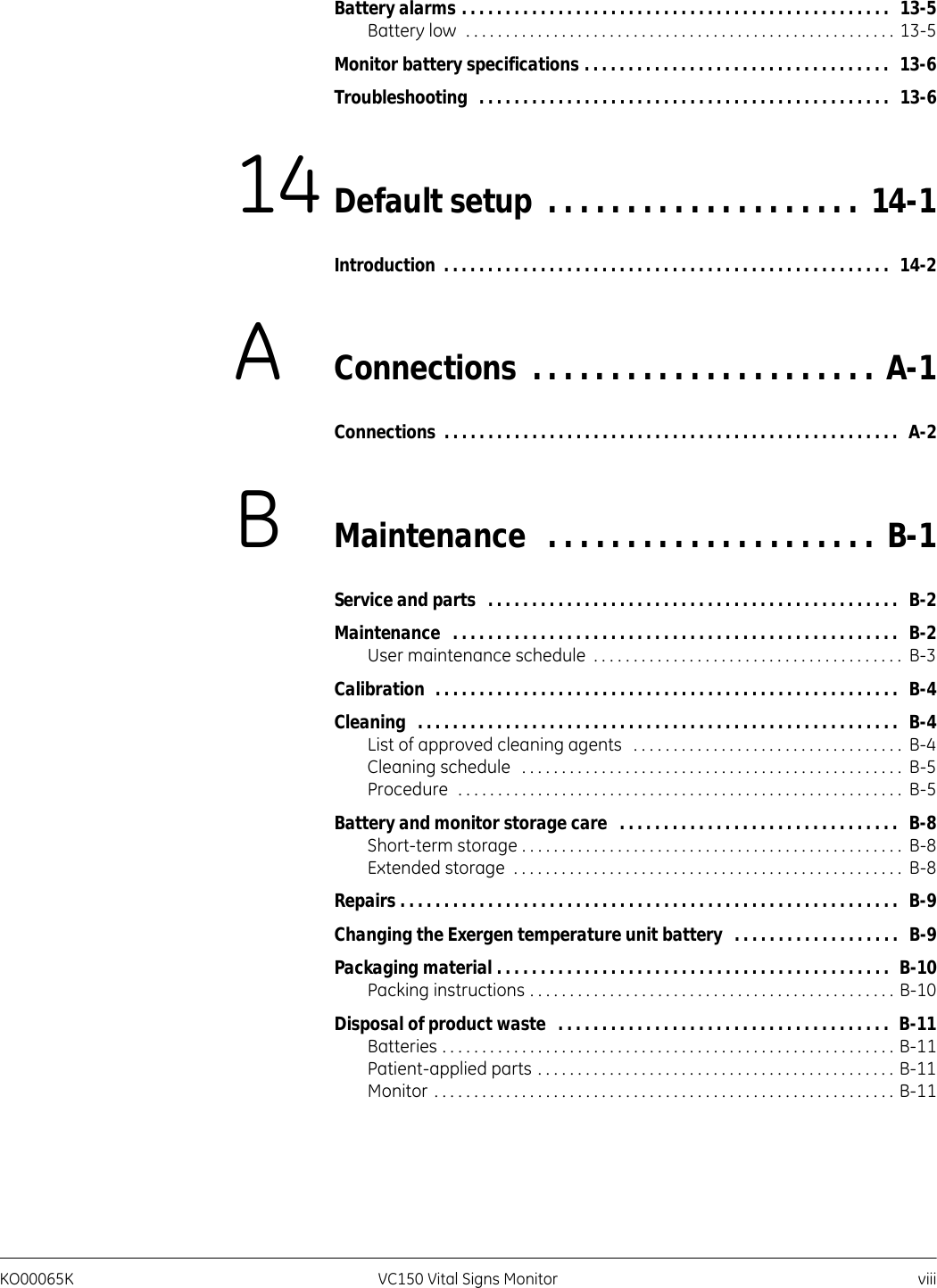


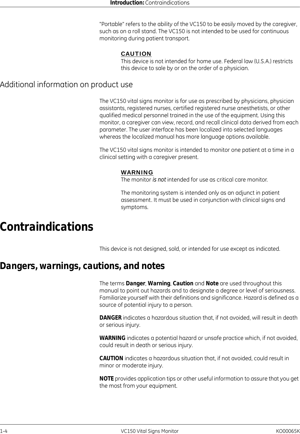
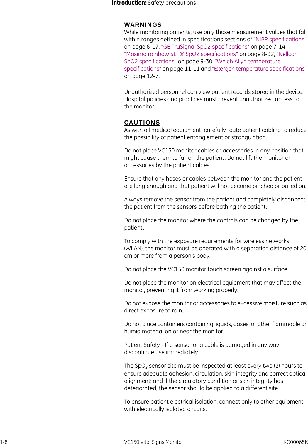


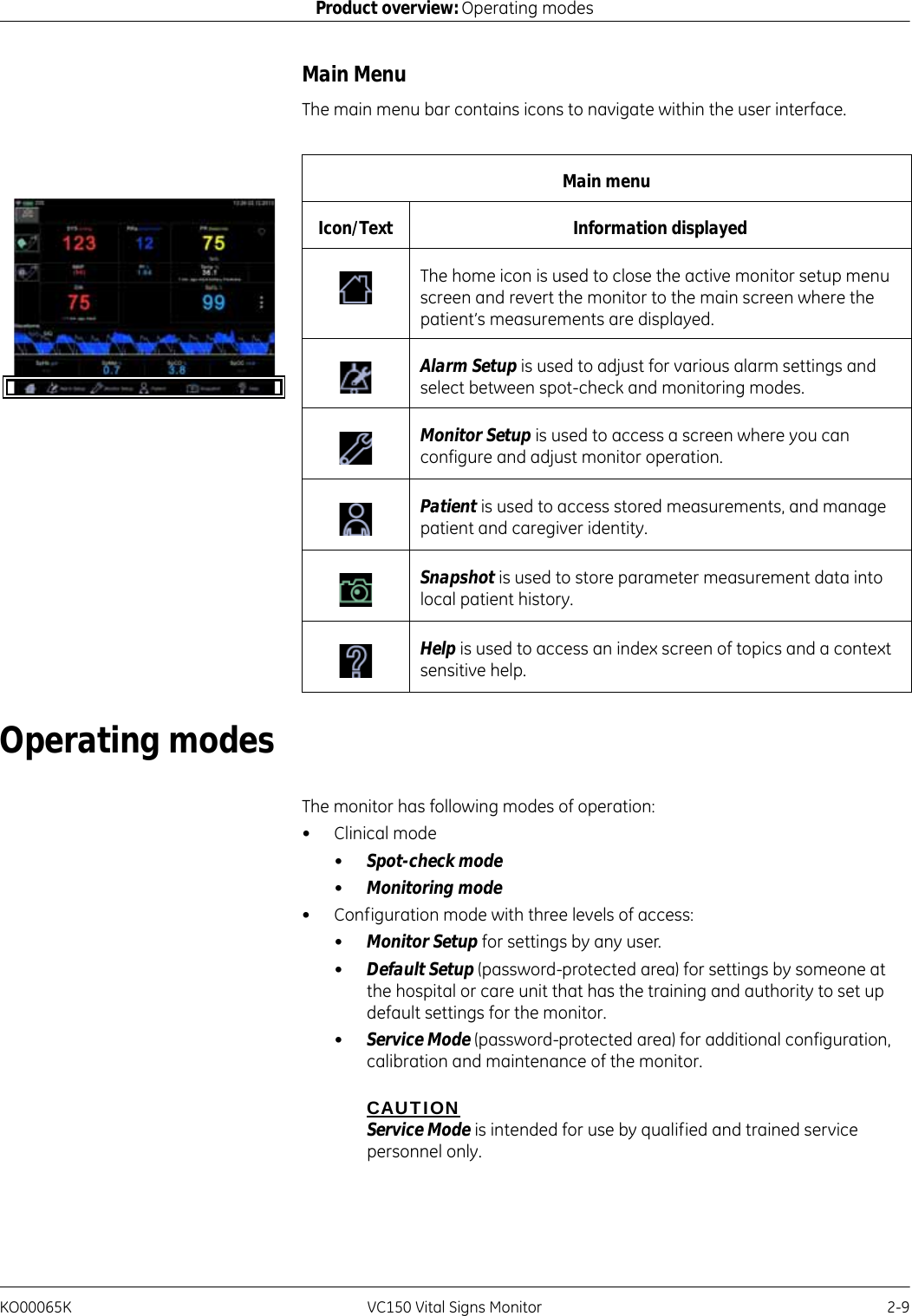
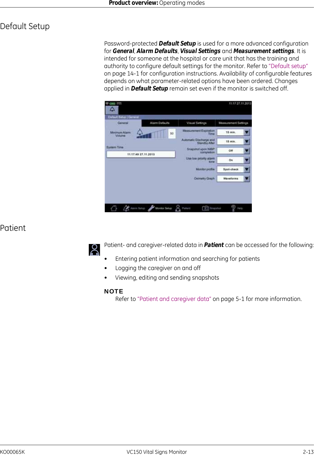
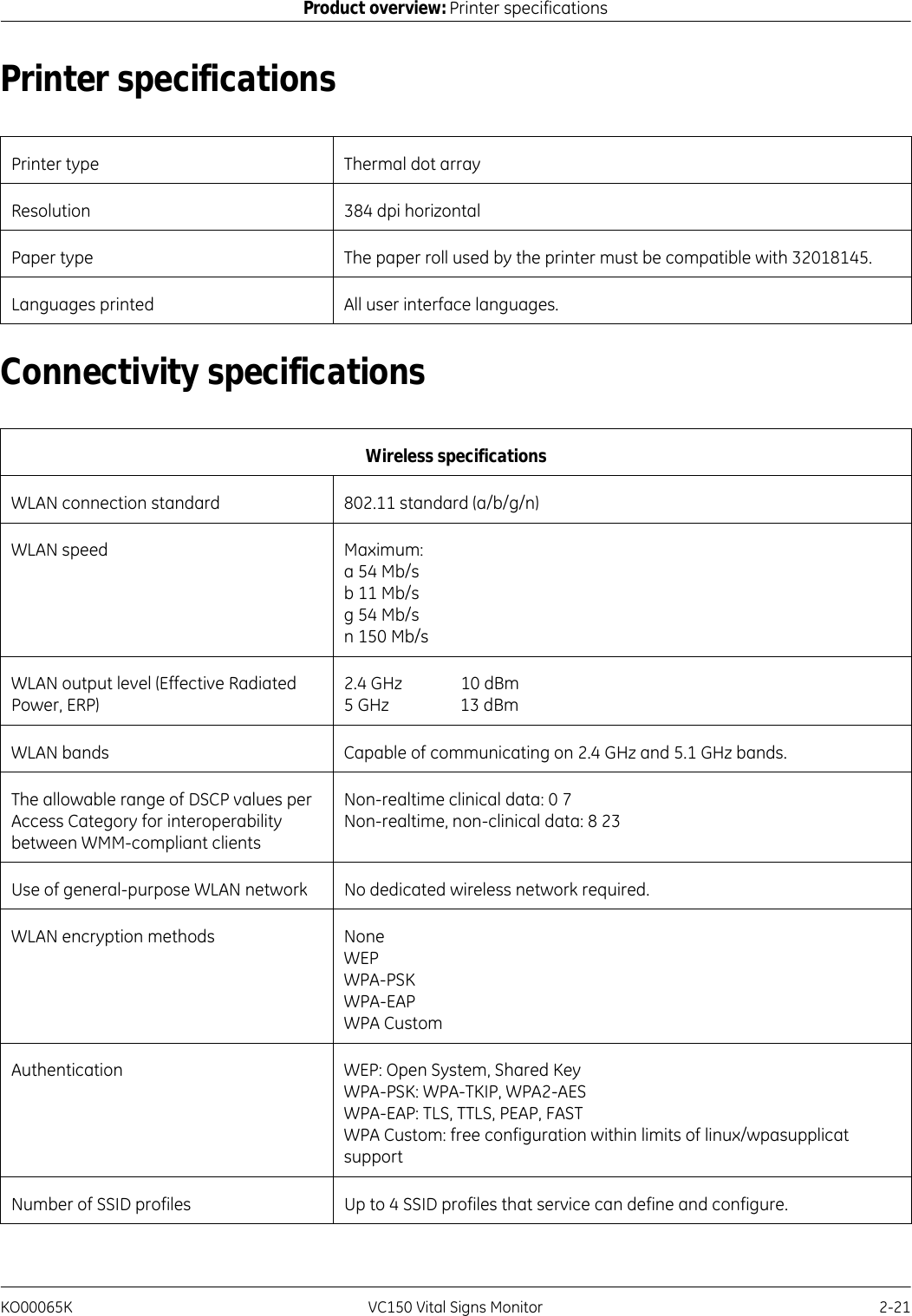


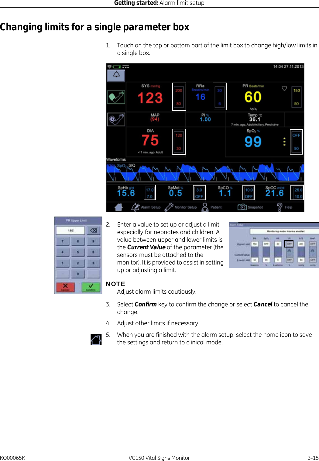


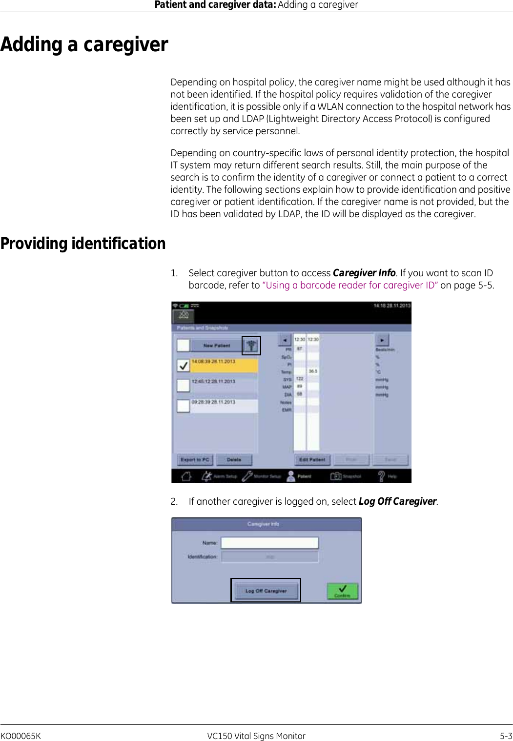
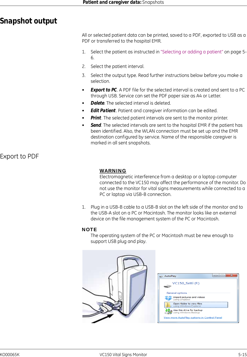
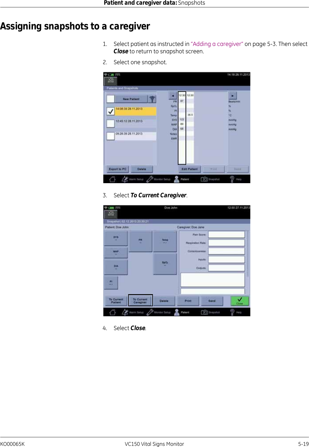

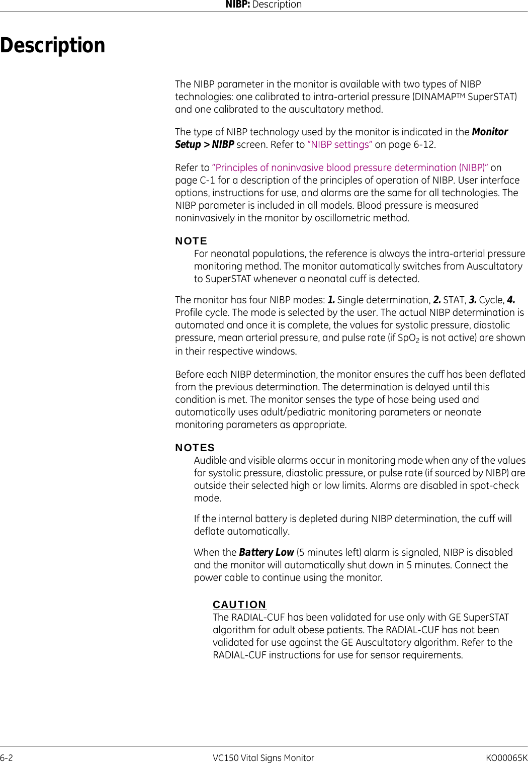
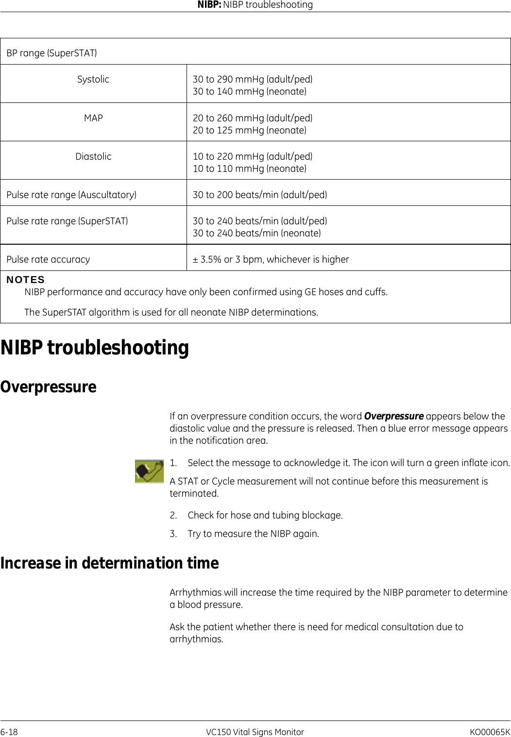


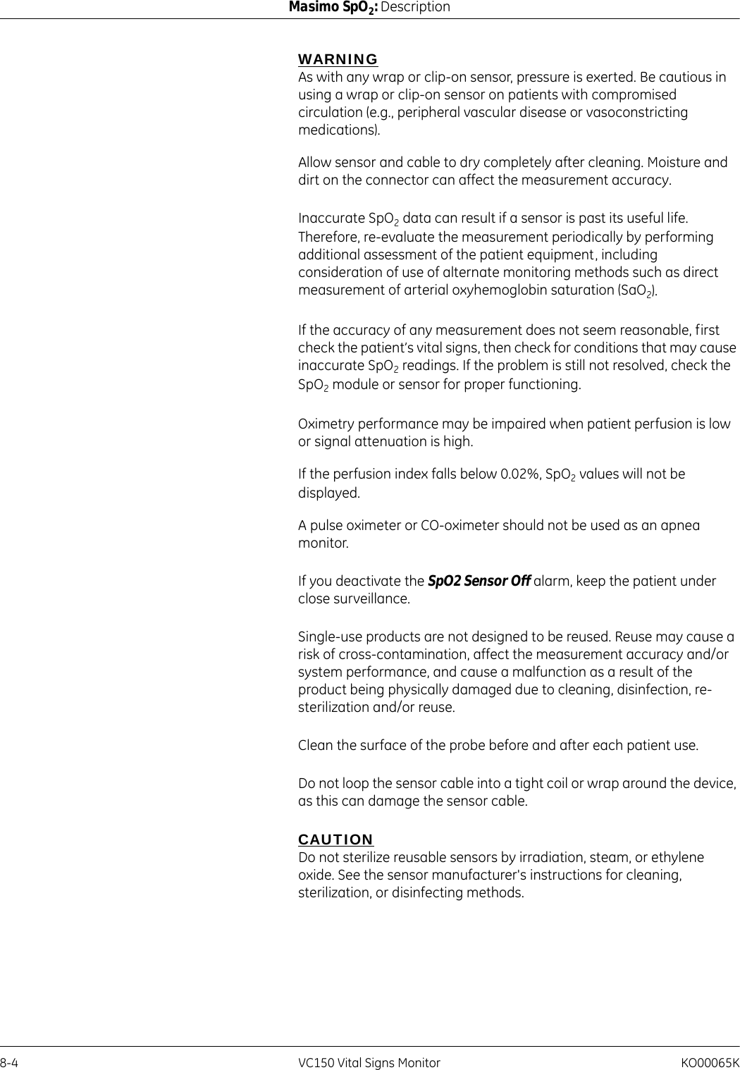

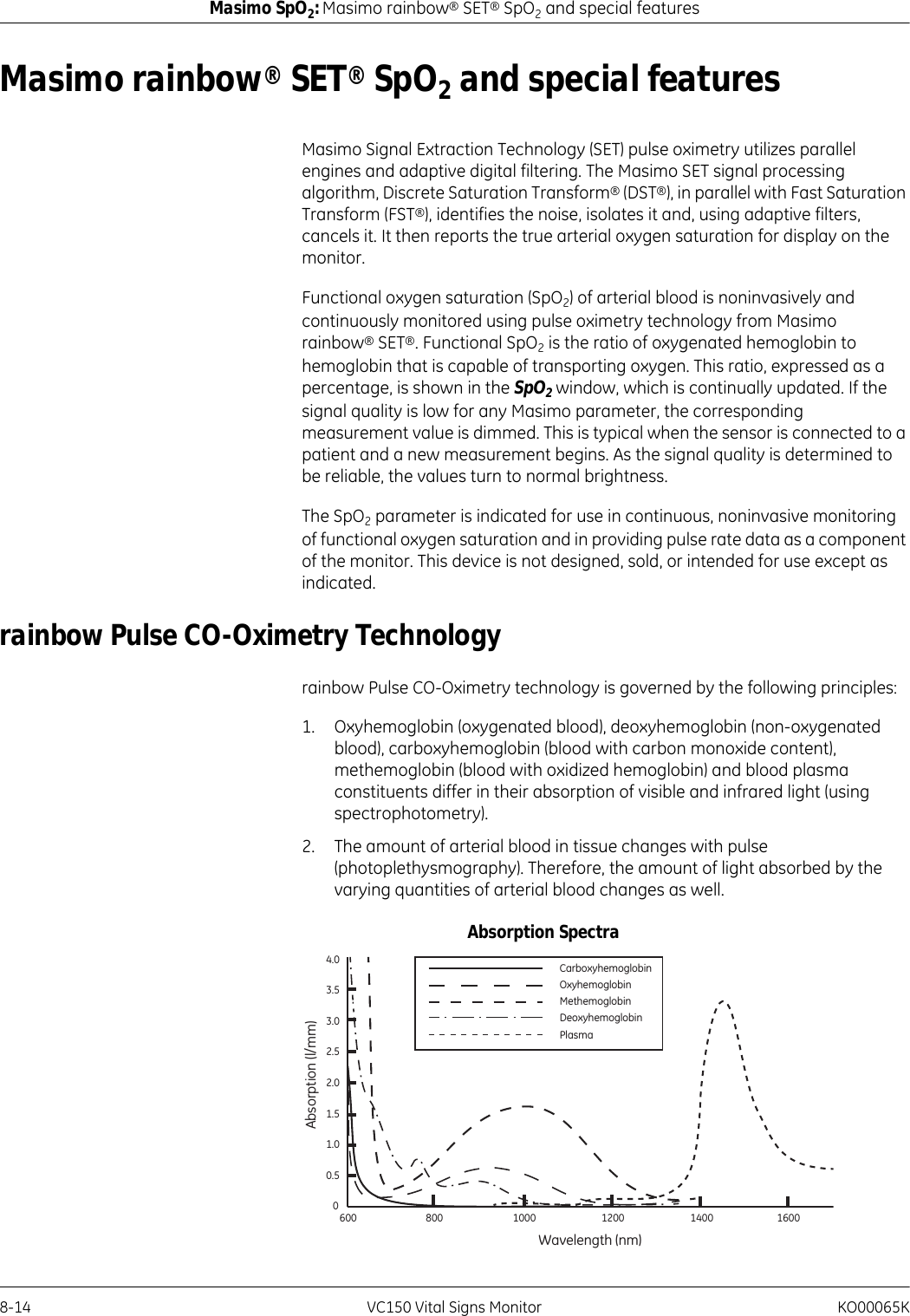
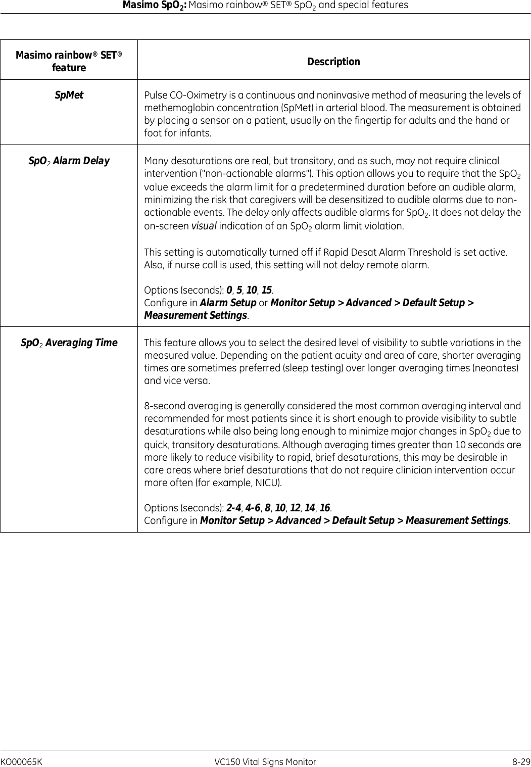
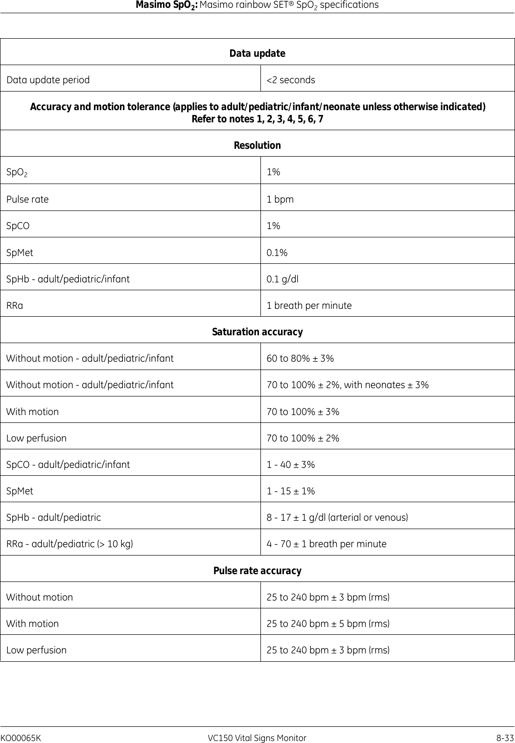
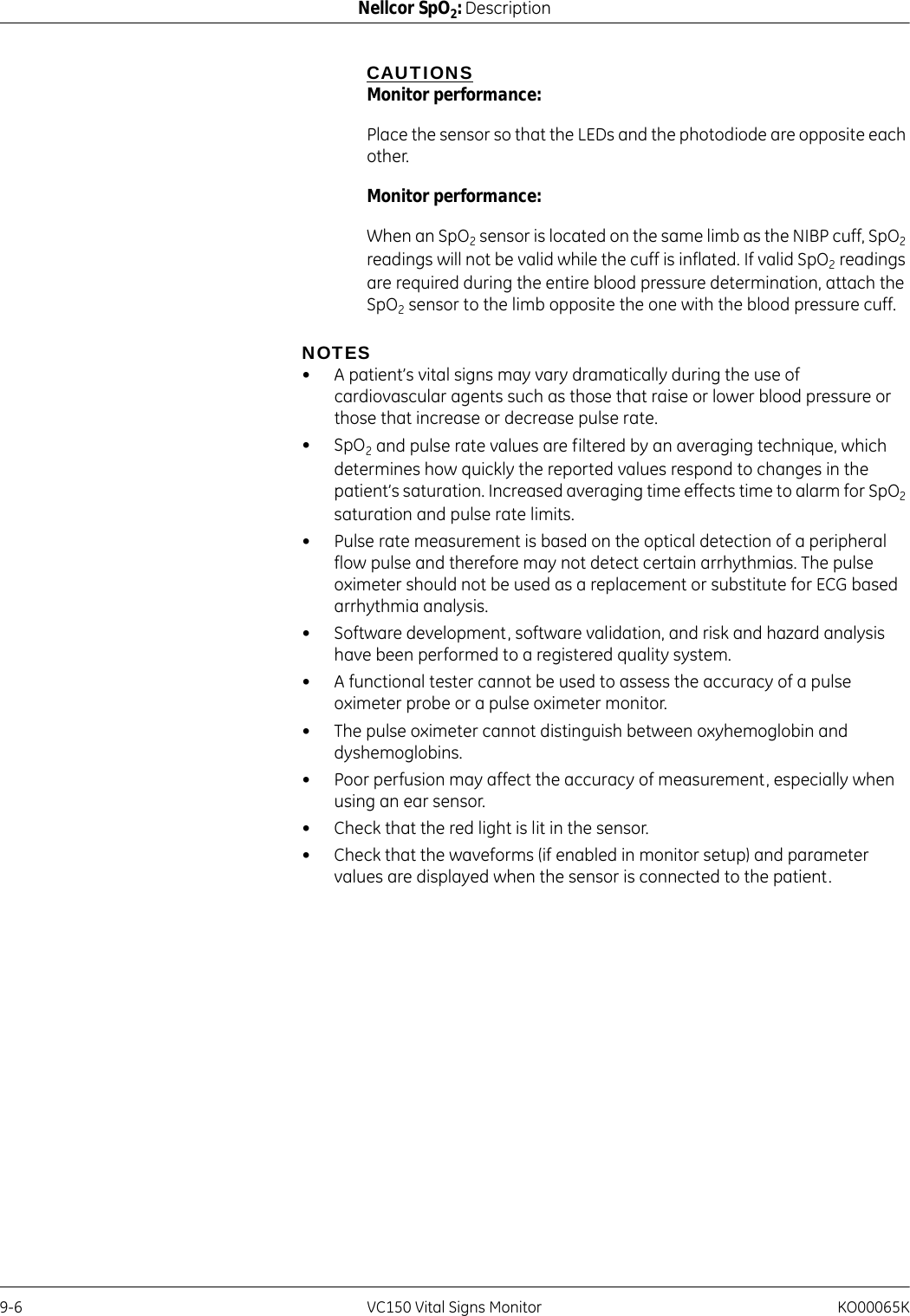
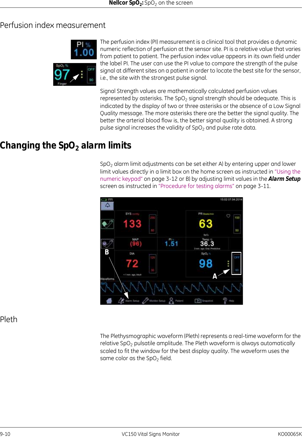
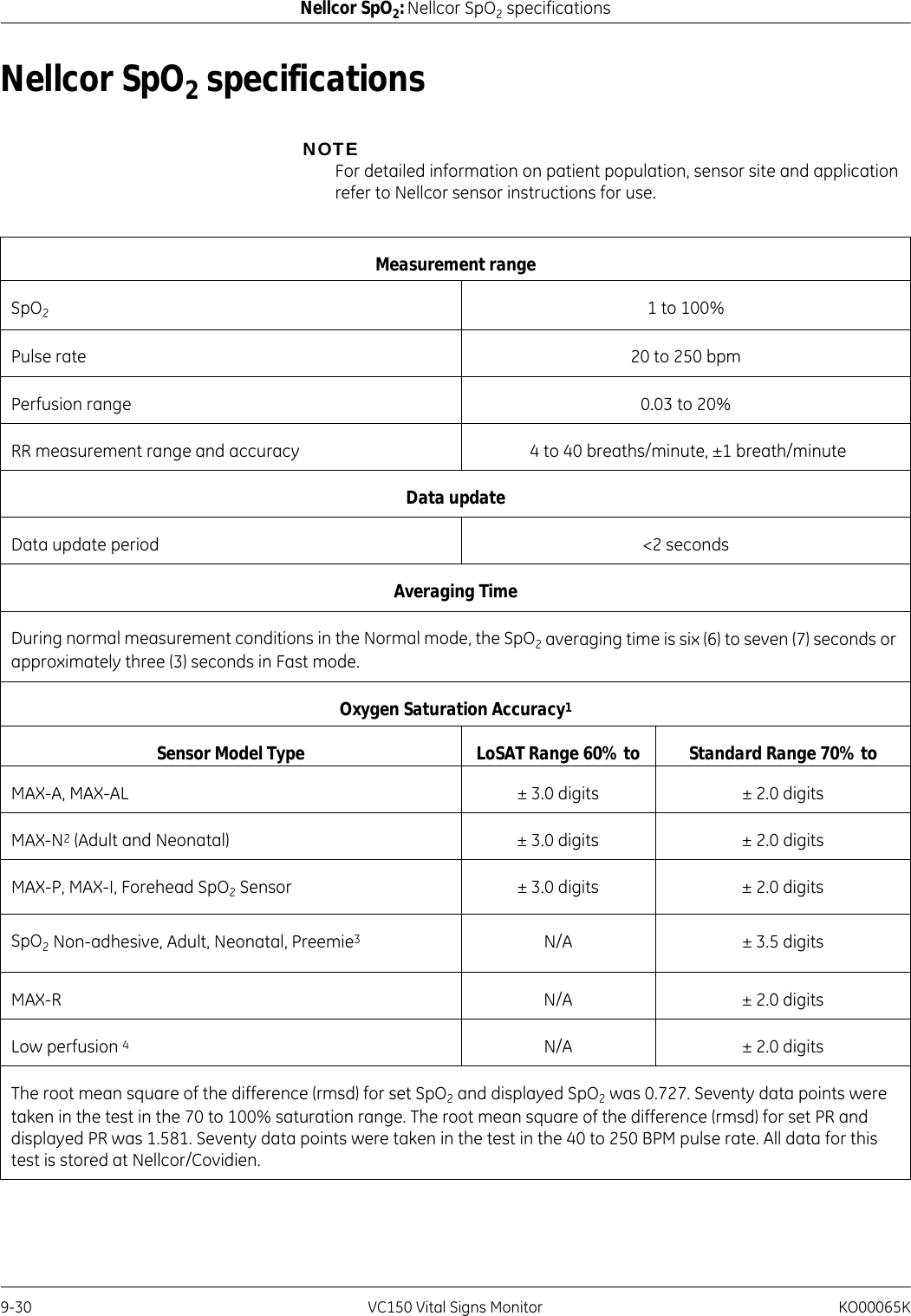
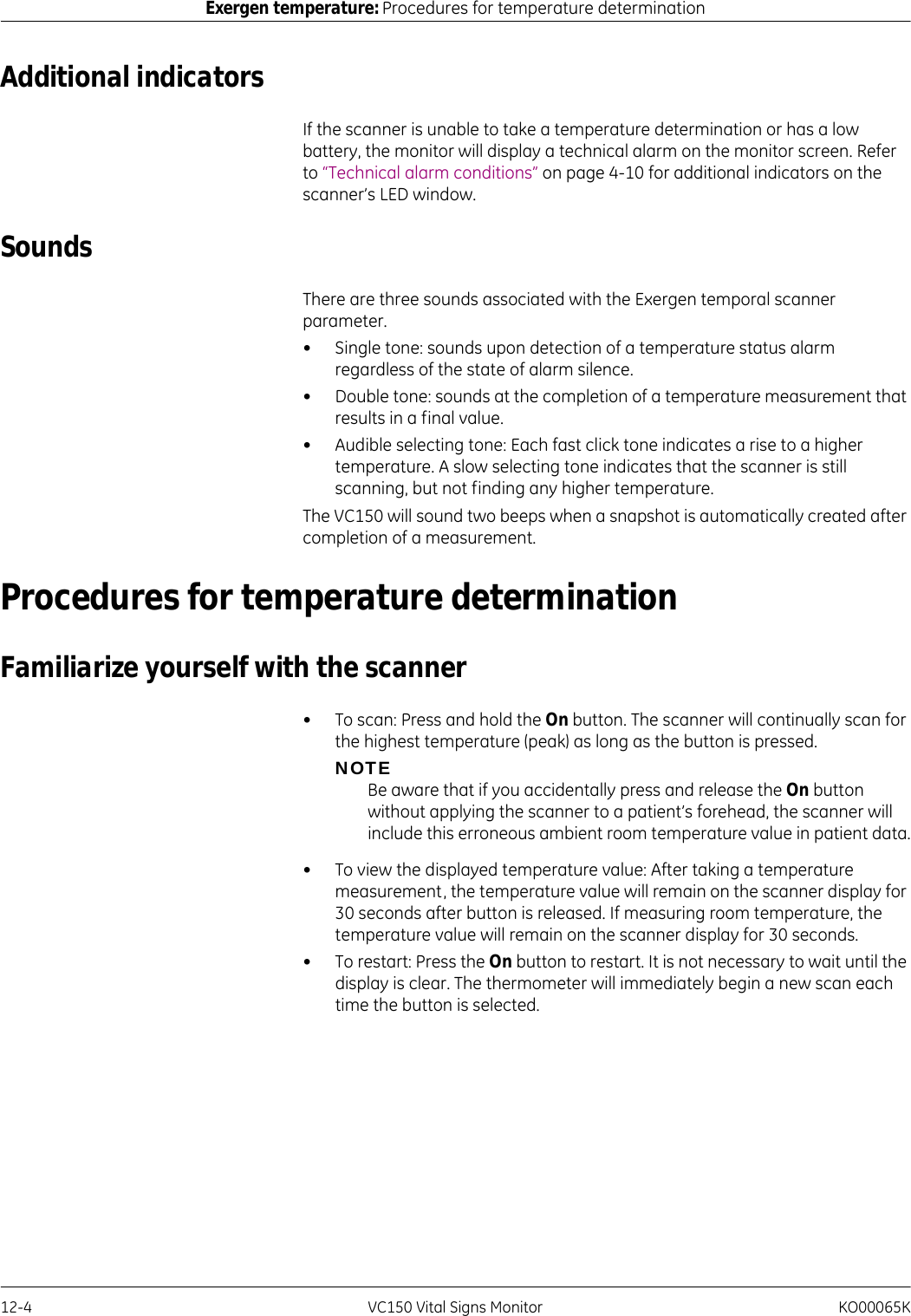
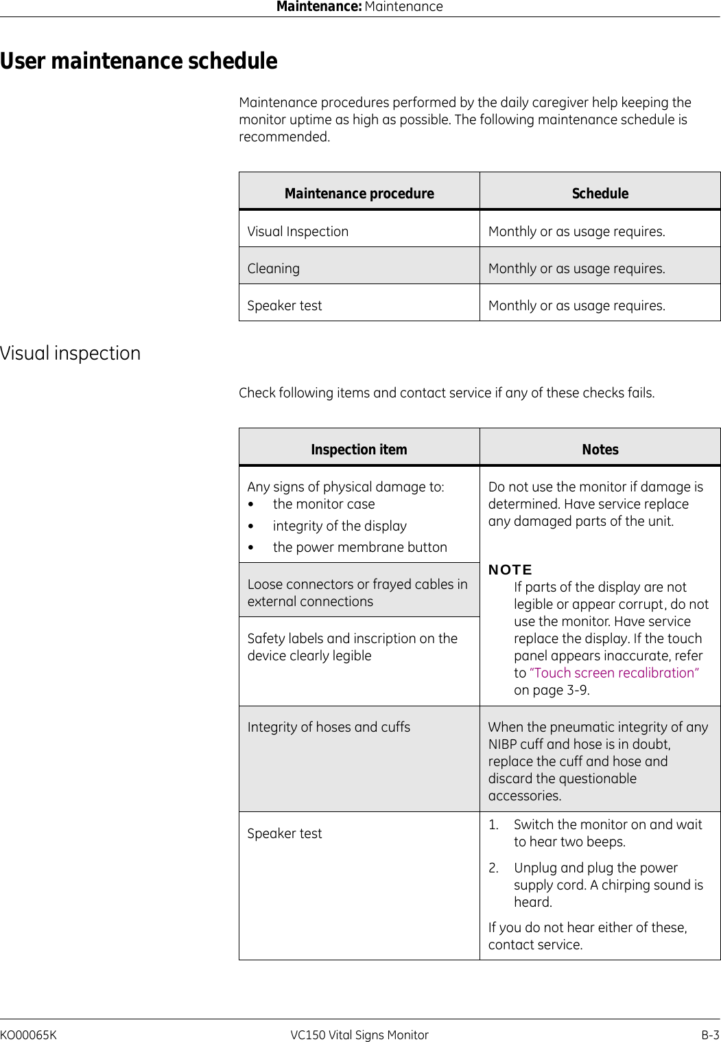
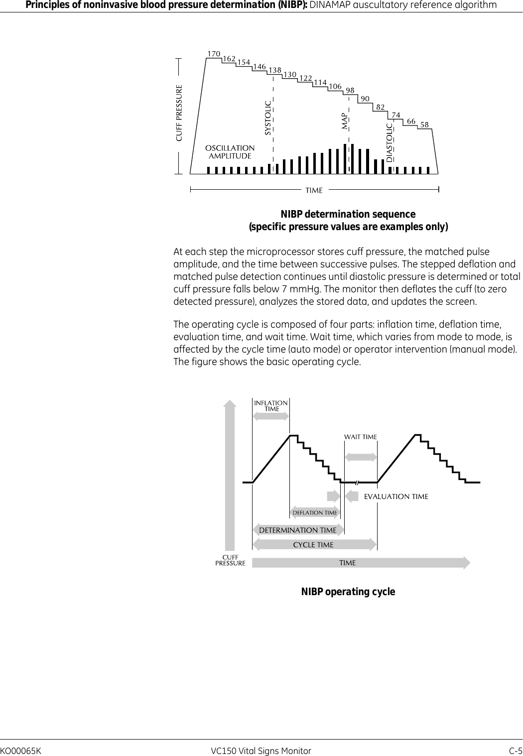
![KO00065K VC150 Vital Signs Monitor 8-15Masimo SpO2: Masimo rainbow® SET® SpO2 and special featuresMasimo rainbow sensors use a multi-wavelength sensor to distinguish between oxygenated blood, deoxygenated blood, blood with carbon monoxide, oxidized blood and blood plasma.Masimo rainbow sensors utilize various light-emitting diodes (LEDs) that pass light through the site to a diode (detector). Signal data is obtained by passing various visible and infrared lights (LEDs, 500 to 1400nm) through a capillary bed (for example, a fingertip, a hand, a foot) and measuring changes in light absorption during the blood pulsatile cycle. This information may be useful to clinicians. The maximum radiant power of the strongest light is rated at 25 mW. The detector receives the light, converts it into an electronic signal and sends it to the Masimo circuit board for calculation.Once the Masimo board receives the signal from the sensor, it utilizes proprietary algorithms to calculate the patient’s functional oxygen saturation (SpO2 [%]), blood levels of carboxyhemoglobin (SpCO [%]), methemoglobin (SpMet [%]), total hemoglobin concentration (SpHb [g/dL]) and pulse rate (PR). The SpCO, SpMet and SpHb measurements rely on a multi-wavelength calibration equation to quantify the percentage of carbon monoxide and methemoglobin and the concentration of total hemoglobin in arterial blood.In an ambient temperature of 35° C the maximum skin surface temperature has been measured at less than 106° F (41° C), verified by Masimo sensor skin temperature test procedure.Pulse CO-Oximetry vs. Drawn Whole Blood MeasurementsWhen SpO2, SpCO, SpMet, and SpHb measurements obtained by Masimo rainbow technology (noninvasive) are compared to drawn whole blood (invasive) measurements by blood gas and/or laboratory CO-Oximetry methods, caution should be taken when evaluating and interpreting the results.The blood gas and/or laboratory CO-Oximetry measurements may differ from the SpO2, SpCO, SpMet, SpHb, and SpOC measurements made by Masimo rainbow technology. Any comparisons should be simultaneous, meaning the measurement on the device should be noted at the exact time that blood is drawn.1. Light Emitting Diodes (LEDs)(7 or more wavelengths)2. Detector12](https://usermanual.wiki/Innokas-Yhtyma/VC150/User-Guide-2418996-Page-183.png)
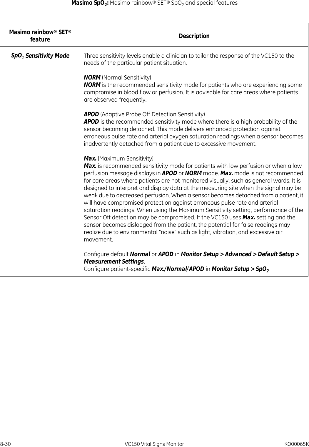
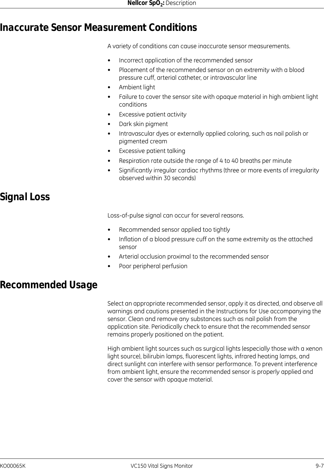
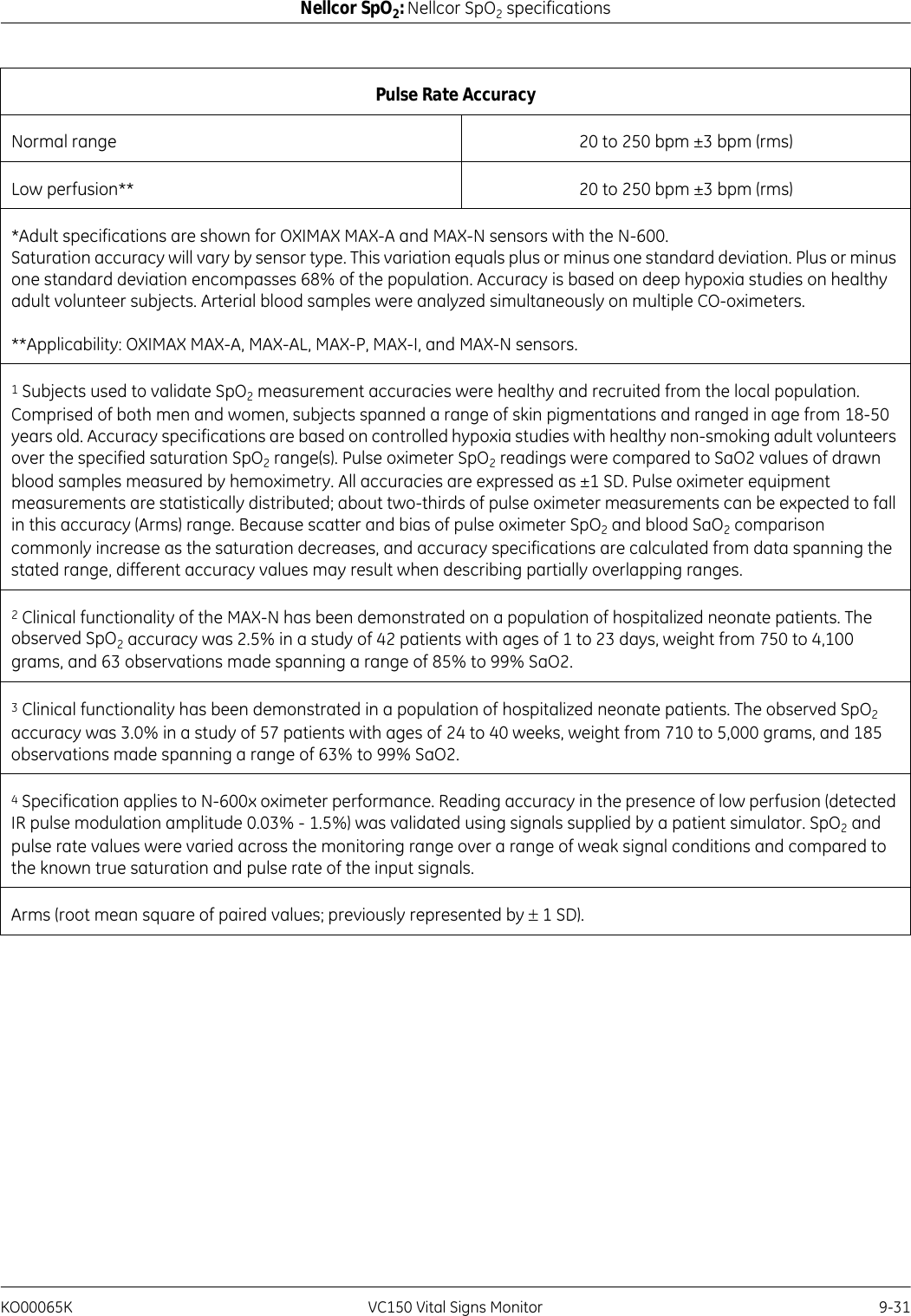
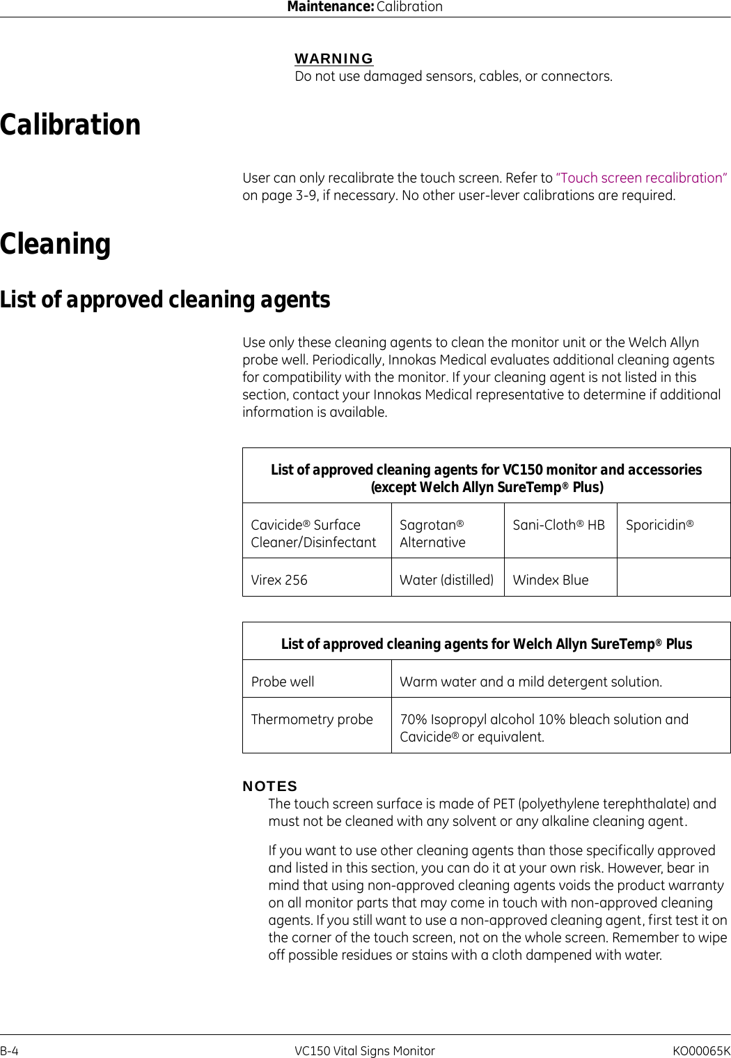
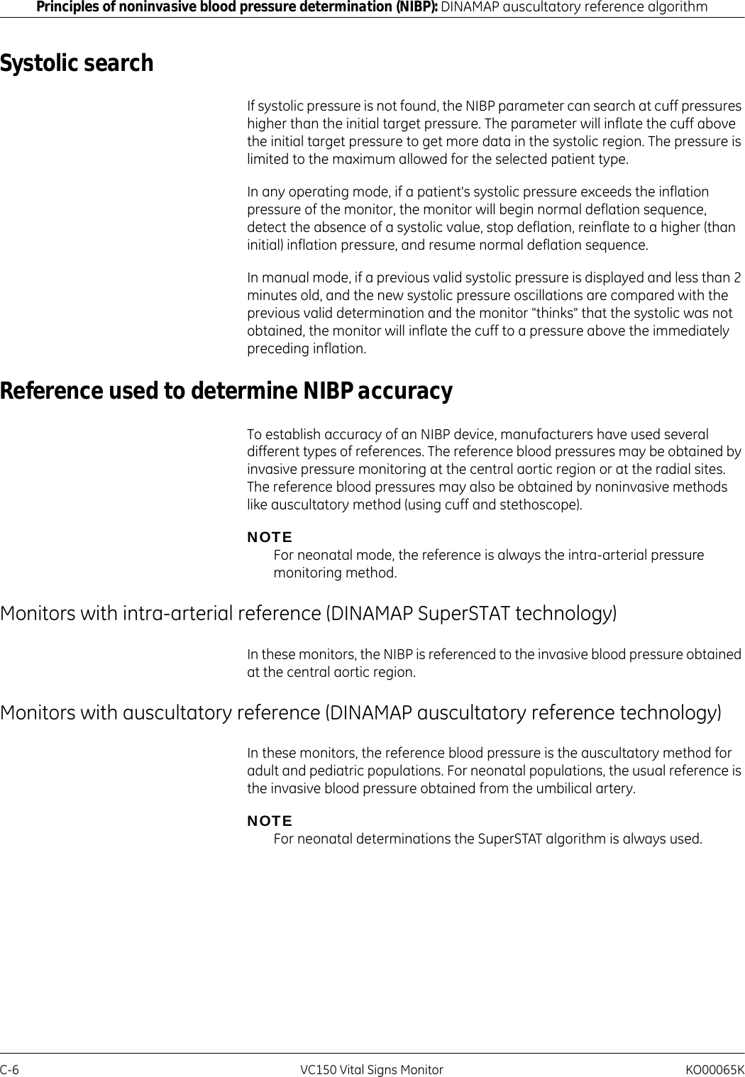
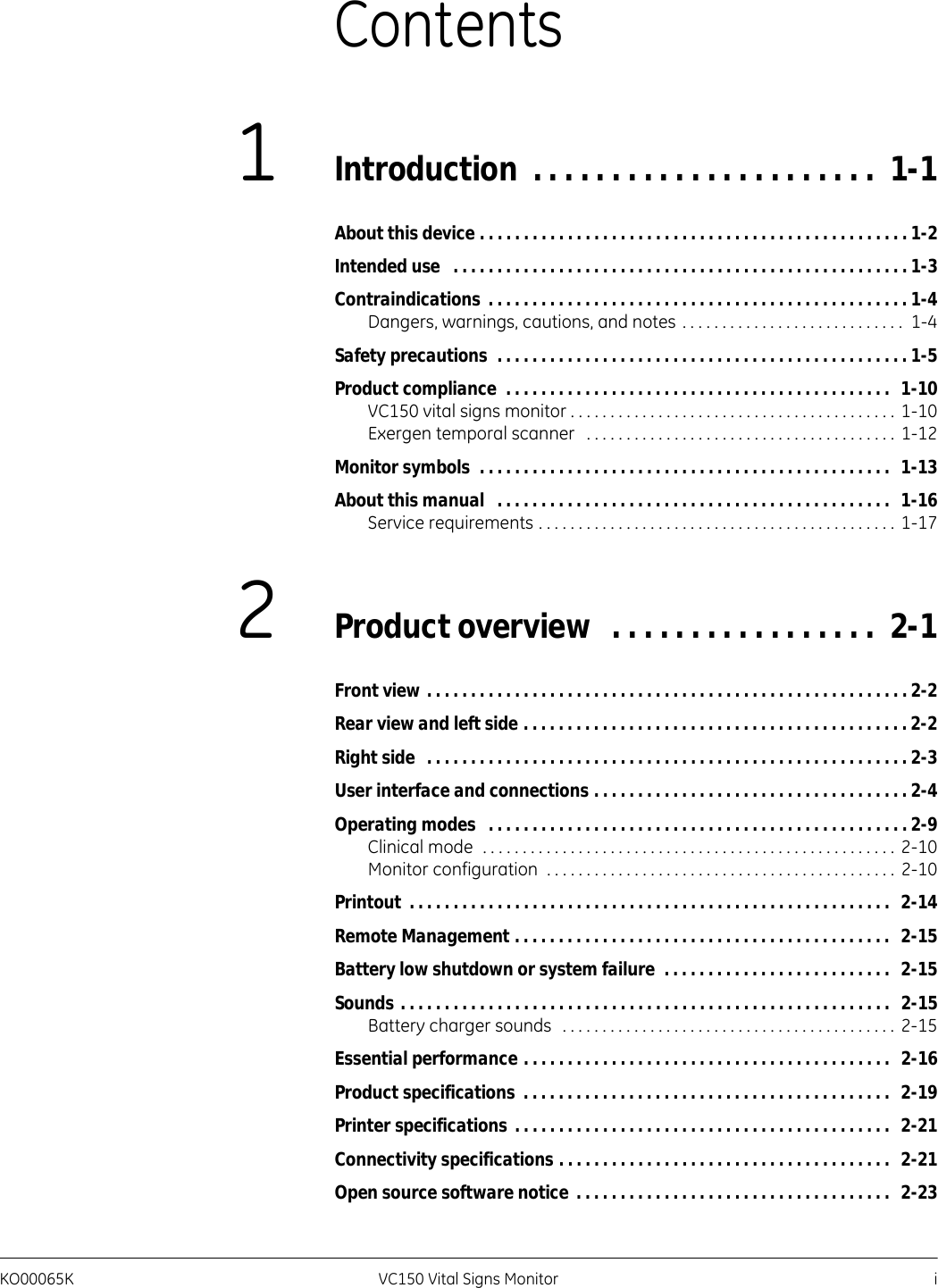
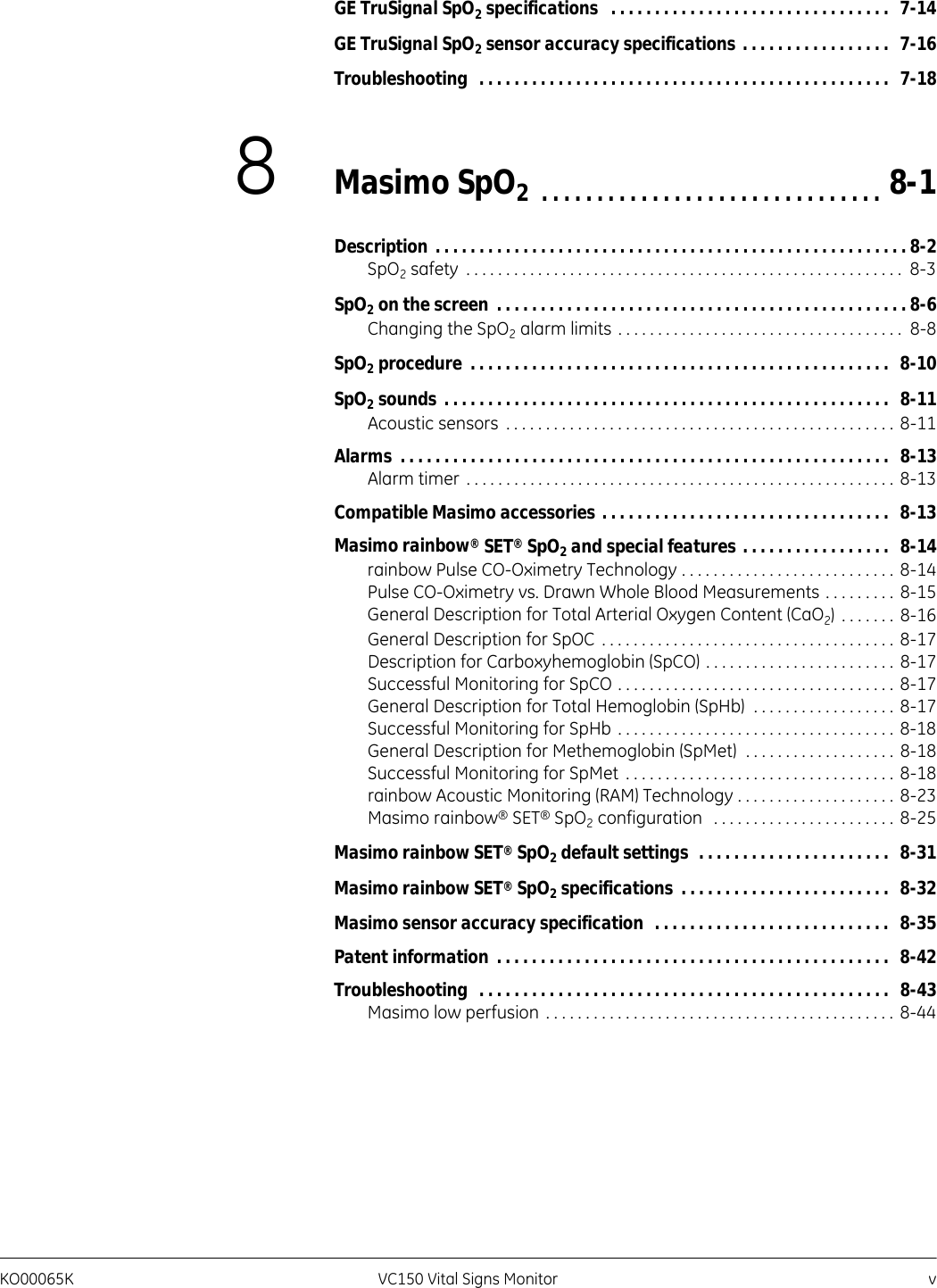
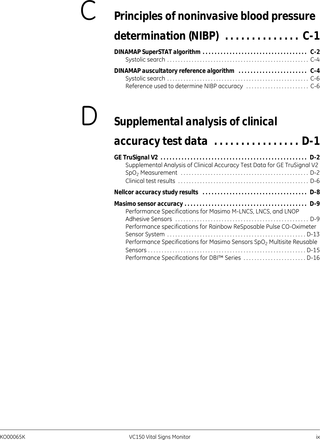
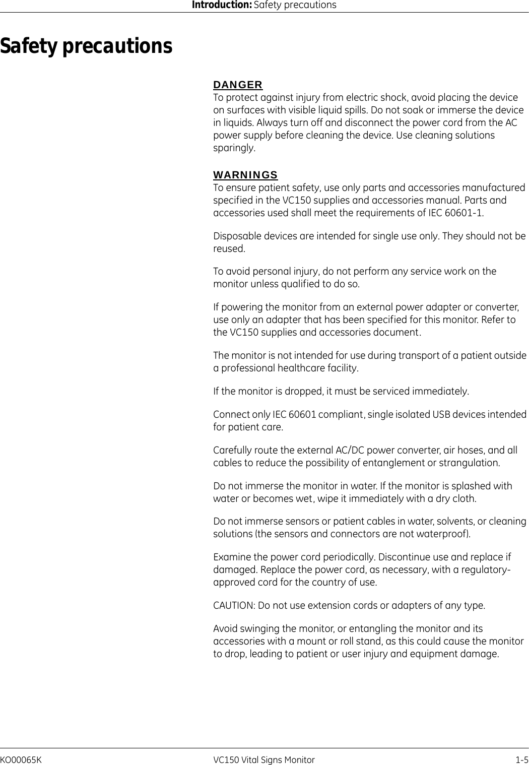
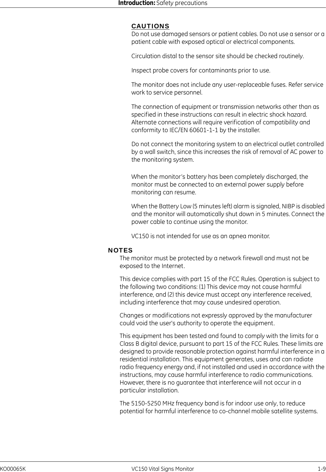
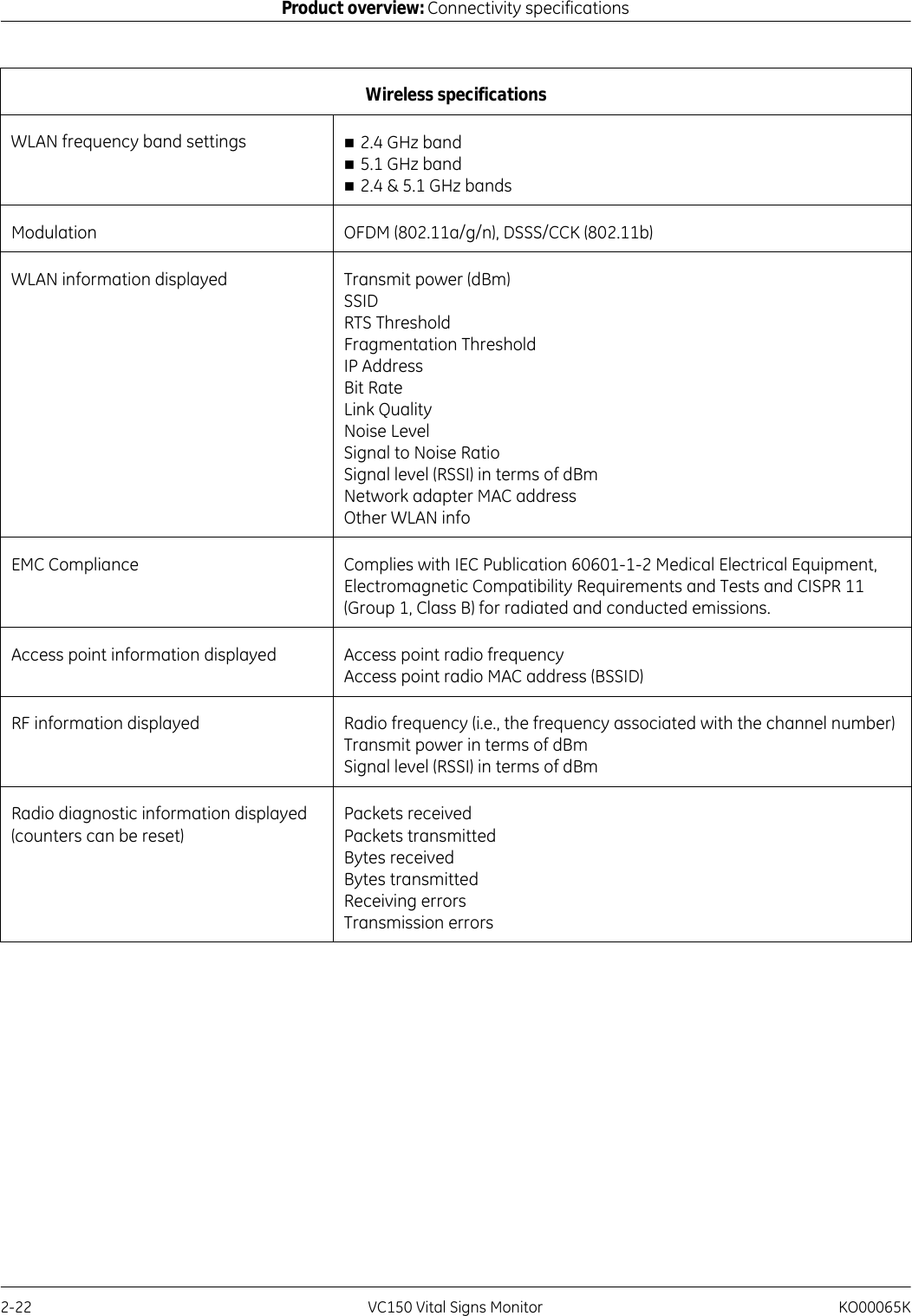
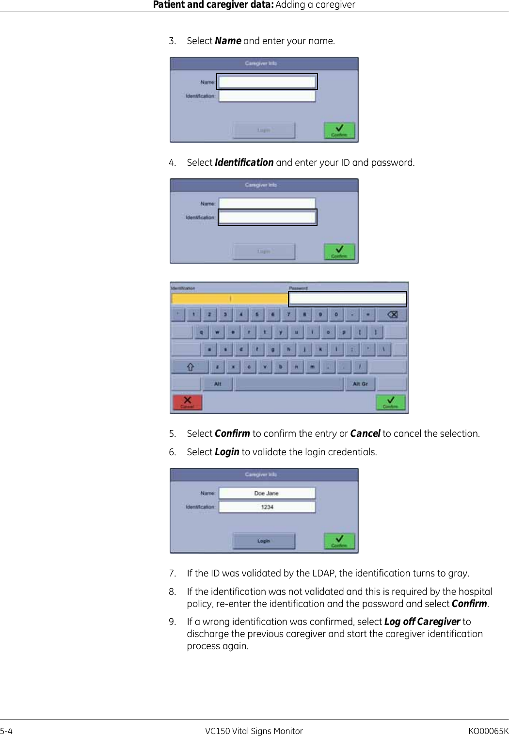
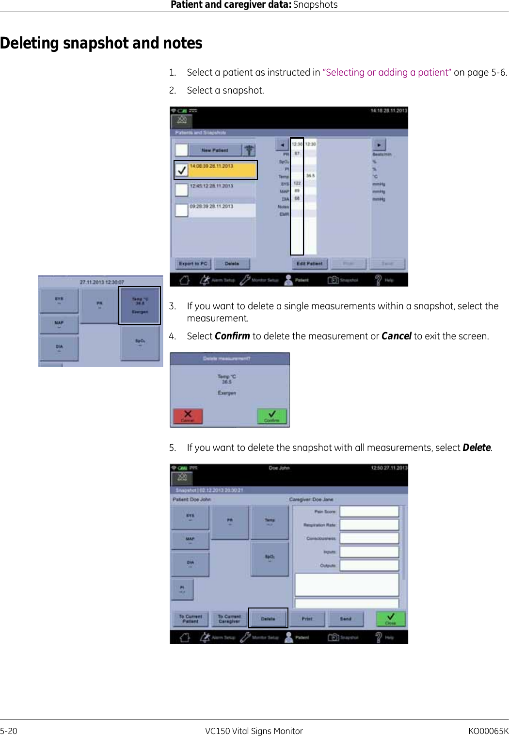
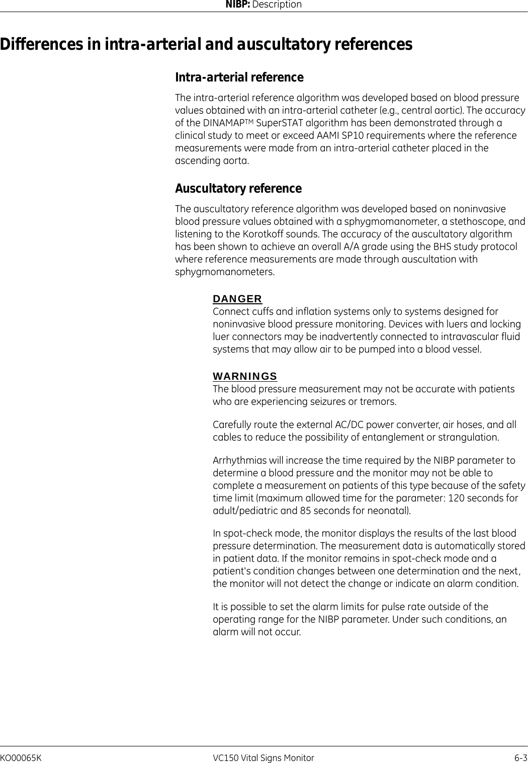
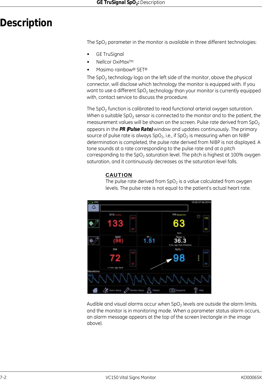
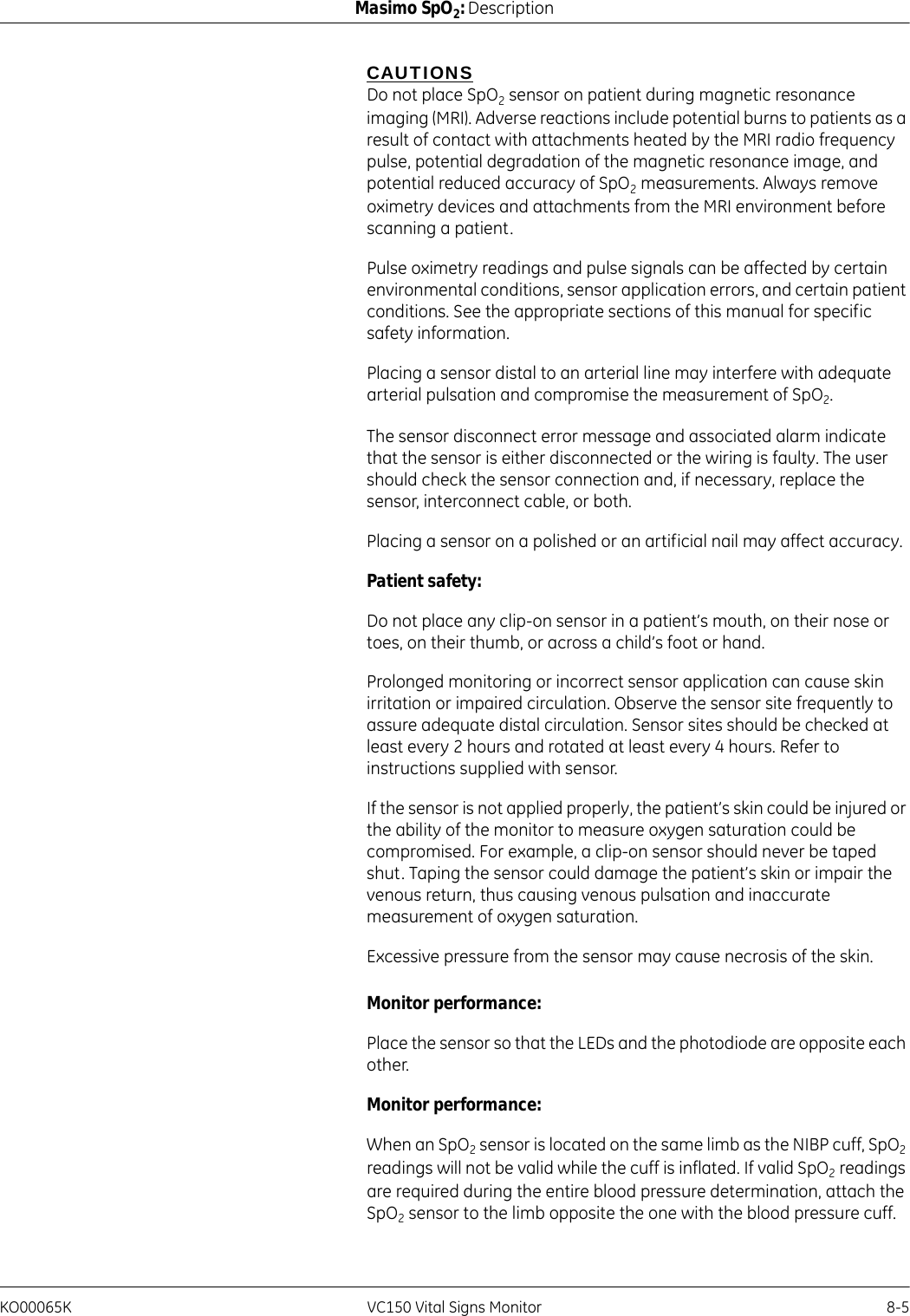
![8-16 VC150 Vital Signs Monitor KO00065KMasimo SpO2: Masimo rainbow® SET® SpO2 and special featuresIn the case of SpO2, different results are usually obtained from the arterial blood gas sample if the calculated measurement is not appropriately corrected for the effects of variables that shift the relationship between the partial pressure of oxygen (PO2) and saturation, such as: pH,temperature, the partial pressure of carbon dioxide (PCO2), 2,3-DPG, and fetal hemoglobin. In the case of SpCO, different results are also expected if concentration of methemoglobin in the blood gas sample is abnormal (greater than 2% for methemoglobin concentration).High levels of bilirubin may cause erroneous SpO2, SpMet, SpCO, and SpHb readings. As blood samples are usually taken over a period of 20 seconds (the time it takes to draw the blood) a meaningful comparison can only be achieved if the oxygen saturation, carboxyhemoglobin, and methemoglobin concentration of the patient are stable and not changing over the period of time that the blood gas sample is taken. Subsequently, blood gas and laboratory CO-Oximetry measurements of SpO2, SpCO, SpMet, SpHb, and SpOC may vary with the rapid administration of fluids and in procedures such as dialysis. Additionally, drawn whole blood testing can be affected by sample handling methods and time elapsed between blood draw and sample testing.Measurements with Low Signal IQ should not be compared to laboratory measurements.General Description for Total Arterial Oxygen Content (CaO2)Oxygen (O2) is carried in the blood in two forms, either dissolved in plasma or combined with hemoglobin. The amount of oxygen in the arterial blood is termed the oxygen content (CaO2) and is measured in units of ml O2/dL blood. One gram of hemoglobin (Hb) can carry 1.34 ml of oxygen, whereas 100 ml of blood plasma may carry approximately 0.3 ml of oxygen*. The oxygen content is determined mathematically as:CaO2 = 1.34 (ml O2/g Hb) x Hb (g/dL) x HbO2 + PaO2 (mm Hg) x (0.3 ml O2/100 mm Hg/dL)Where HbO2 is the fractional arterial oxygen saturation and PaO2 is the partial pressure of arterial oxygen.For typical PaO2 values, the second part of the above equation (PaO2 [mm Hg] x [0.3 ml O2/ 100 mm Hg/dL]) is approximately 0.3 ml/dL. Furthermore, for typical carboxyhemoglobin and methemoglobin levels, the functional saturation (SpO2) as measured by a pulse oximeter is given by:SpO2 = 1.02 x HbO2*Martin, Laurence. All You Really Need to Know to Interpret Arterial Blood Gases, Second Edition. New York: Lippincott Williams & Wilkins, 1999.](https://usermanual.wiki/Innokas-Yhtyma/VC150/User-Guide-2418996-Page-184.png)
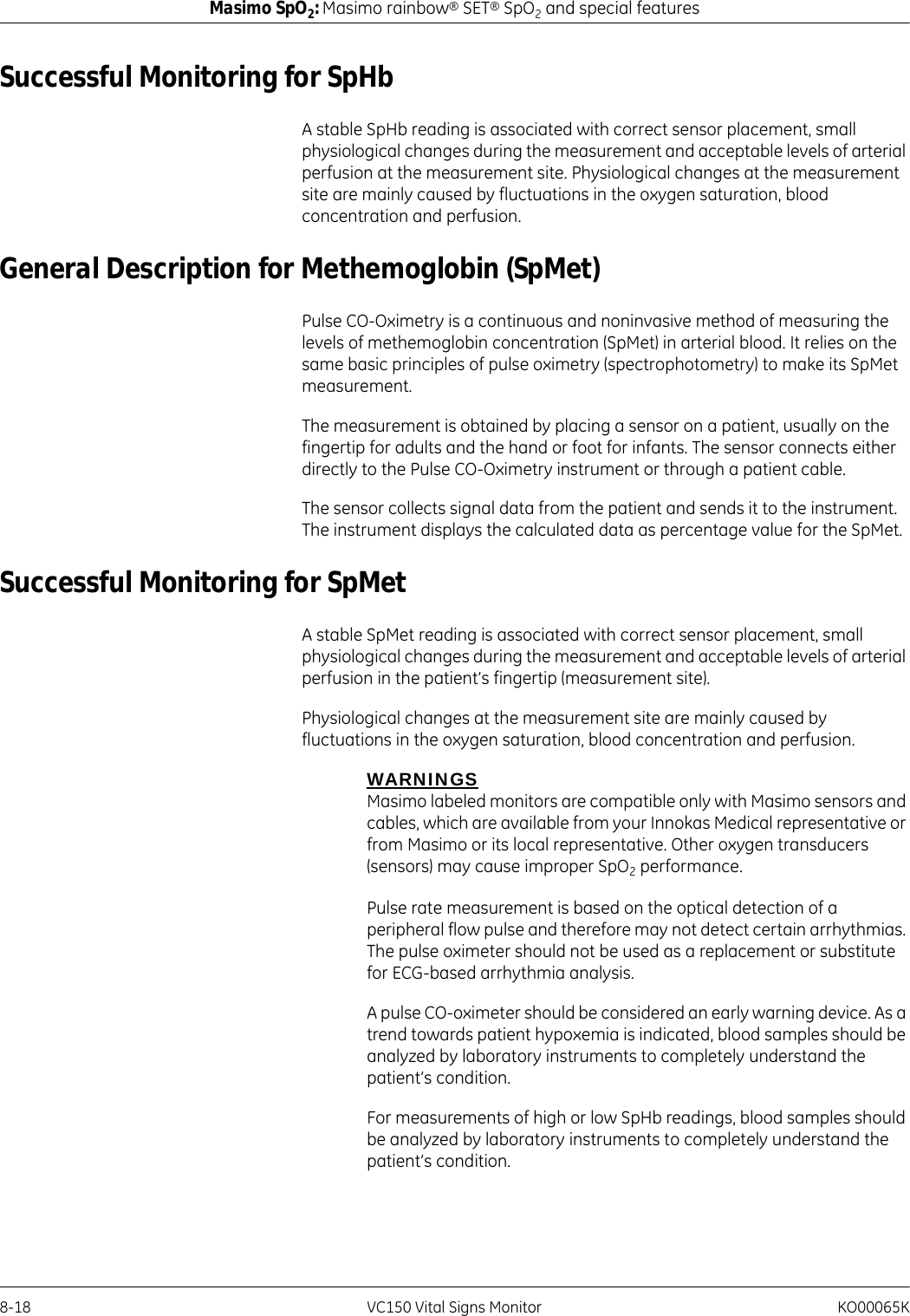
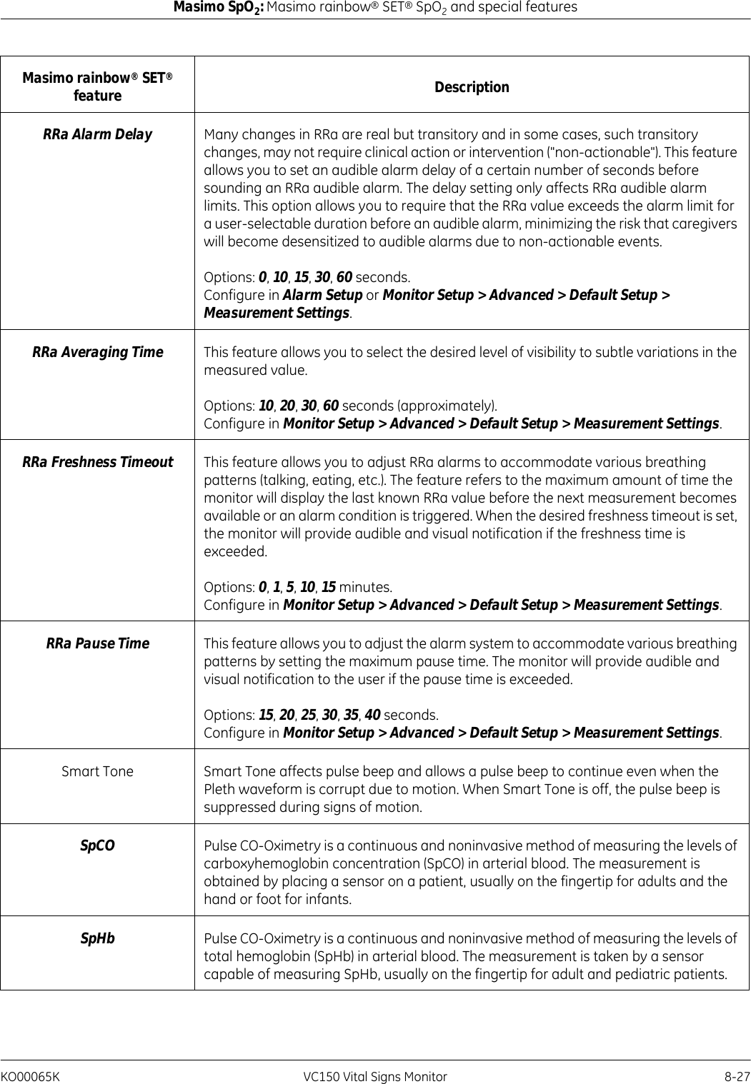
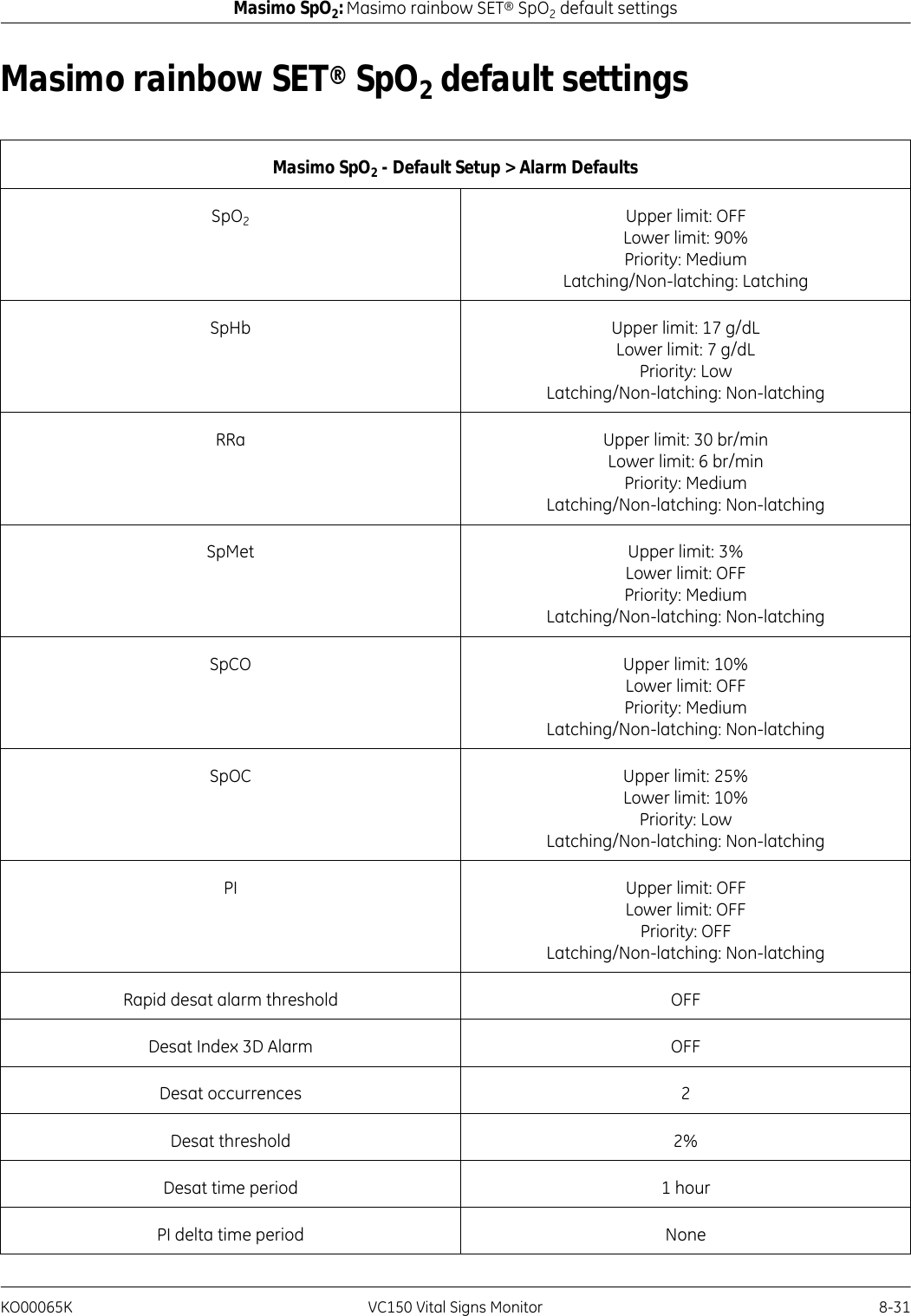
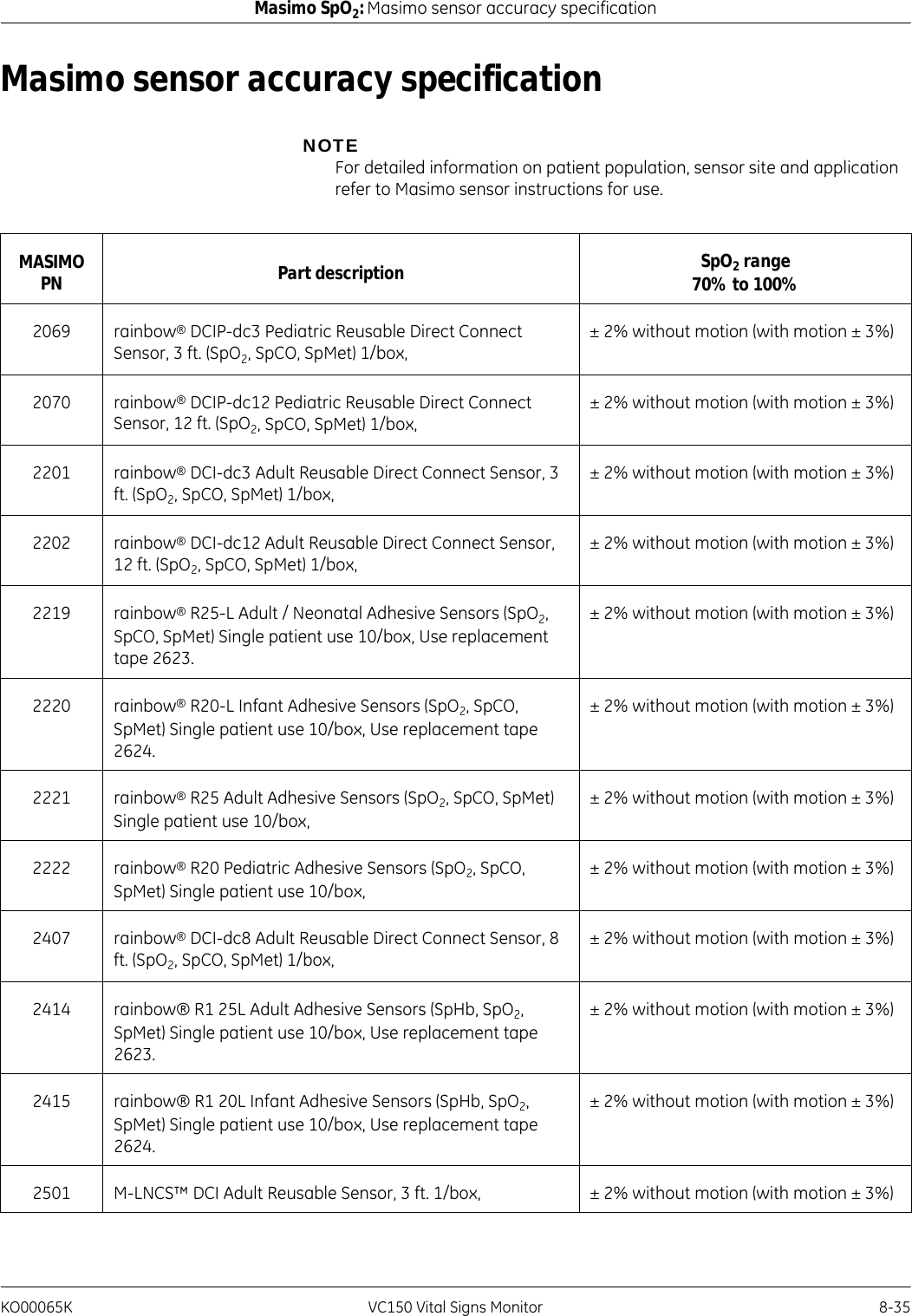
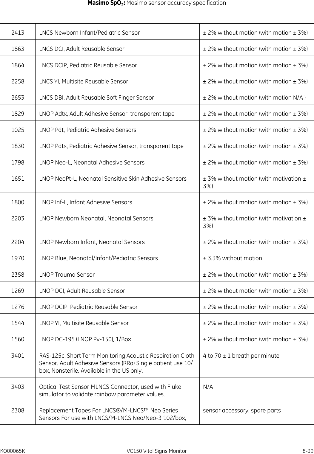
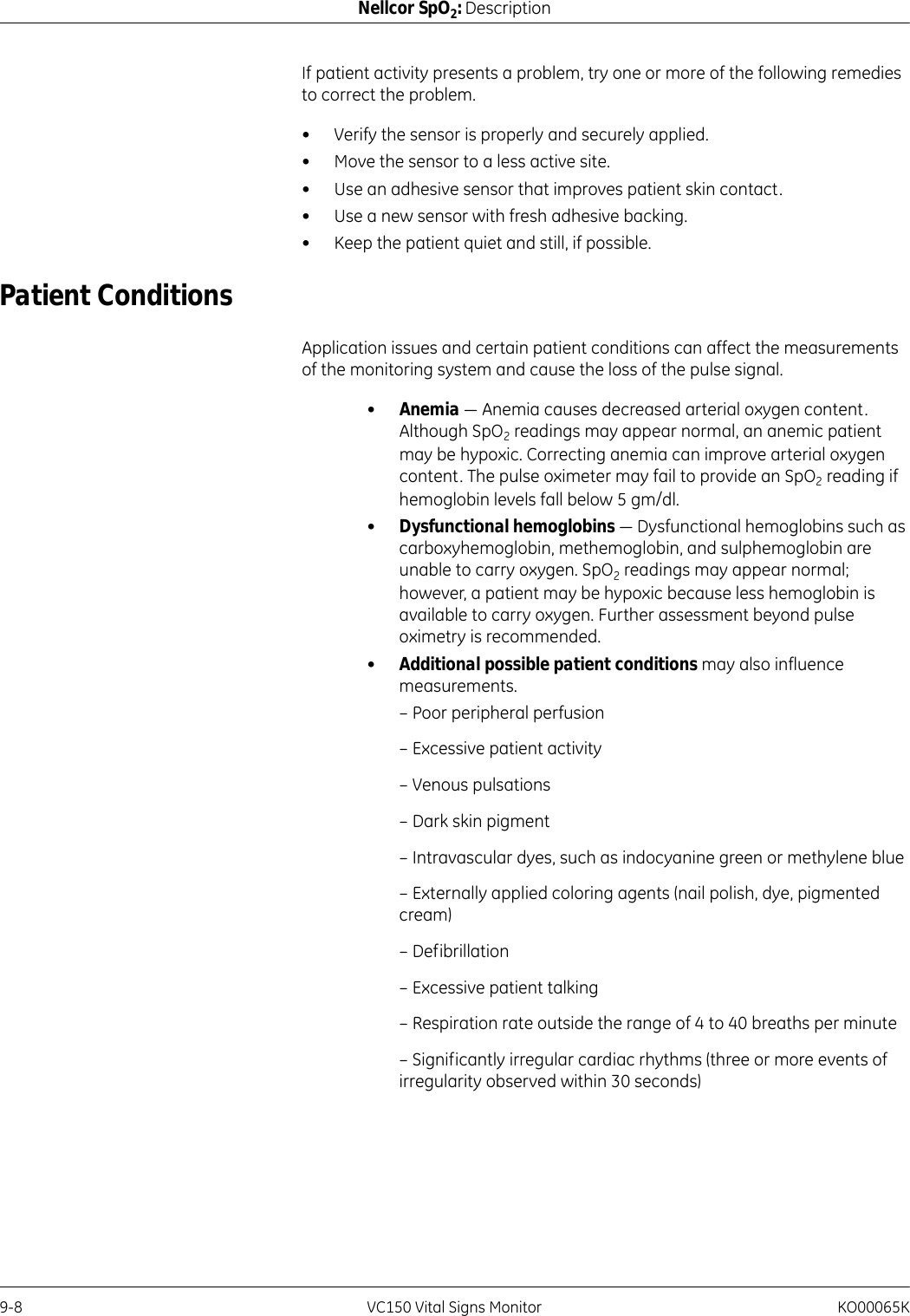
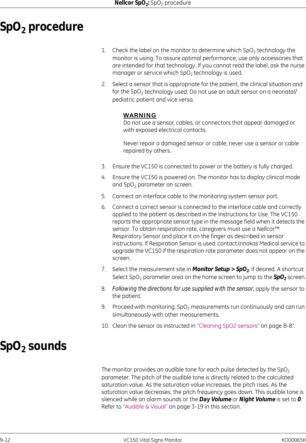
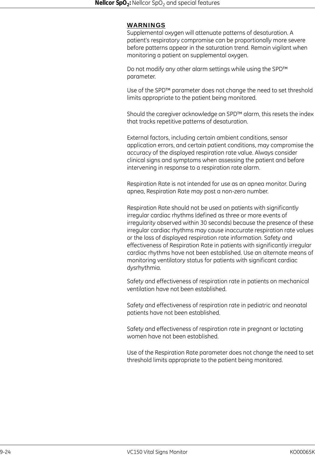
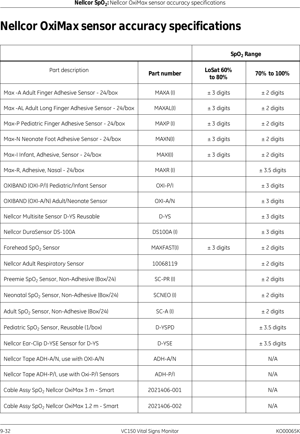
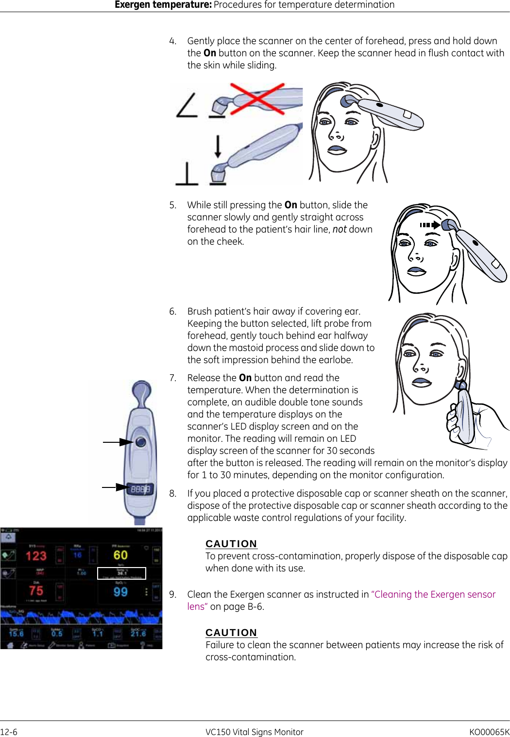
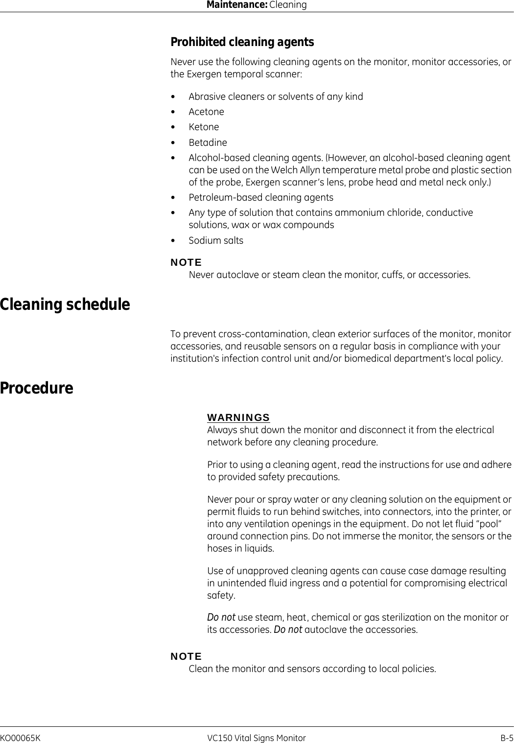
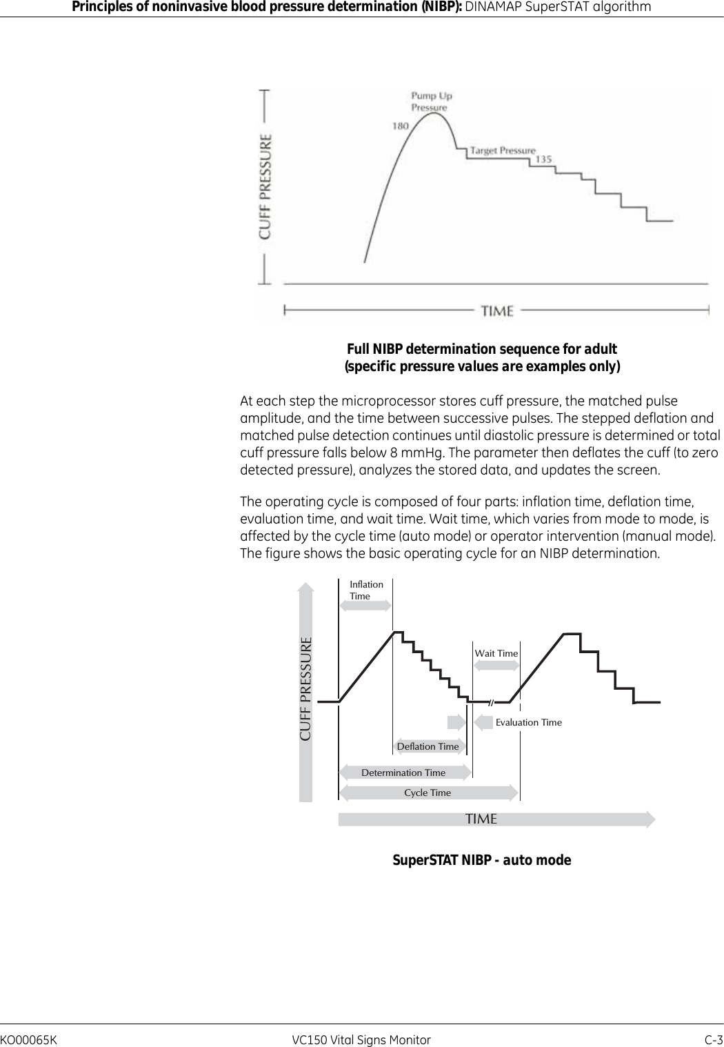
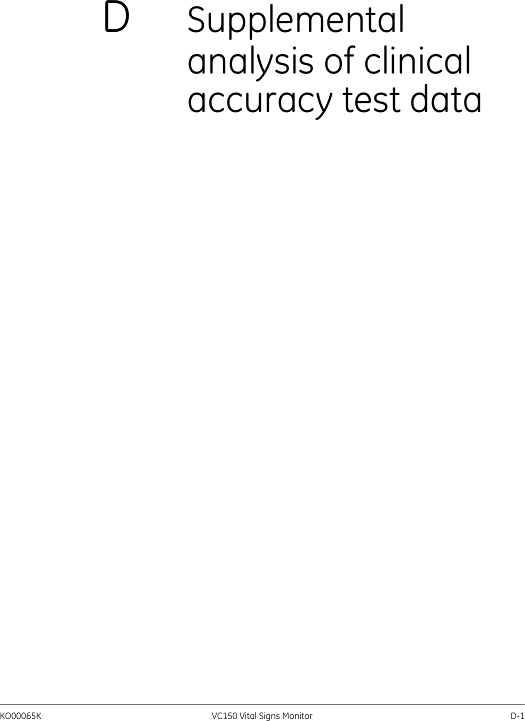
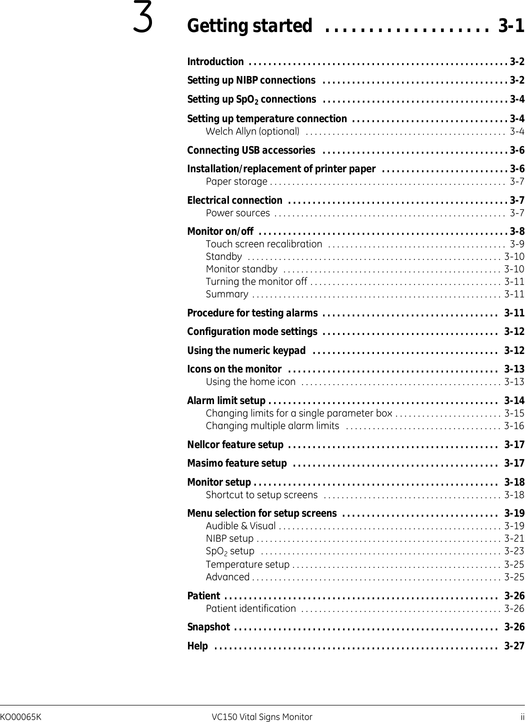
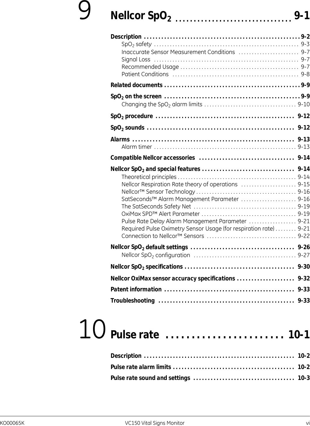
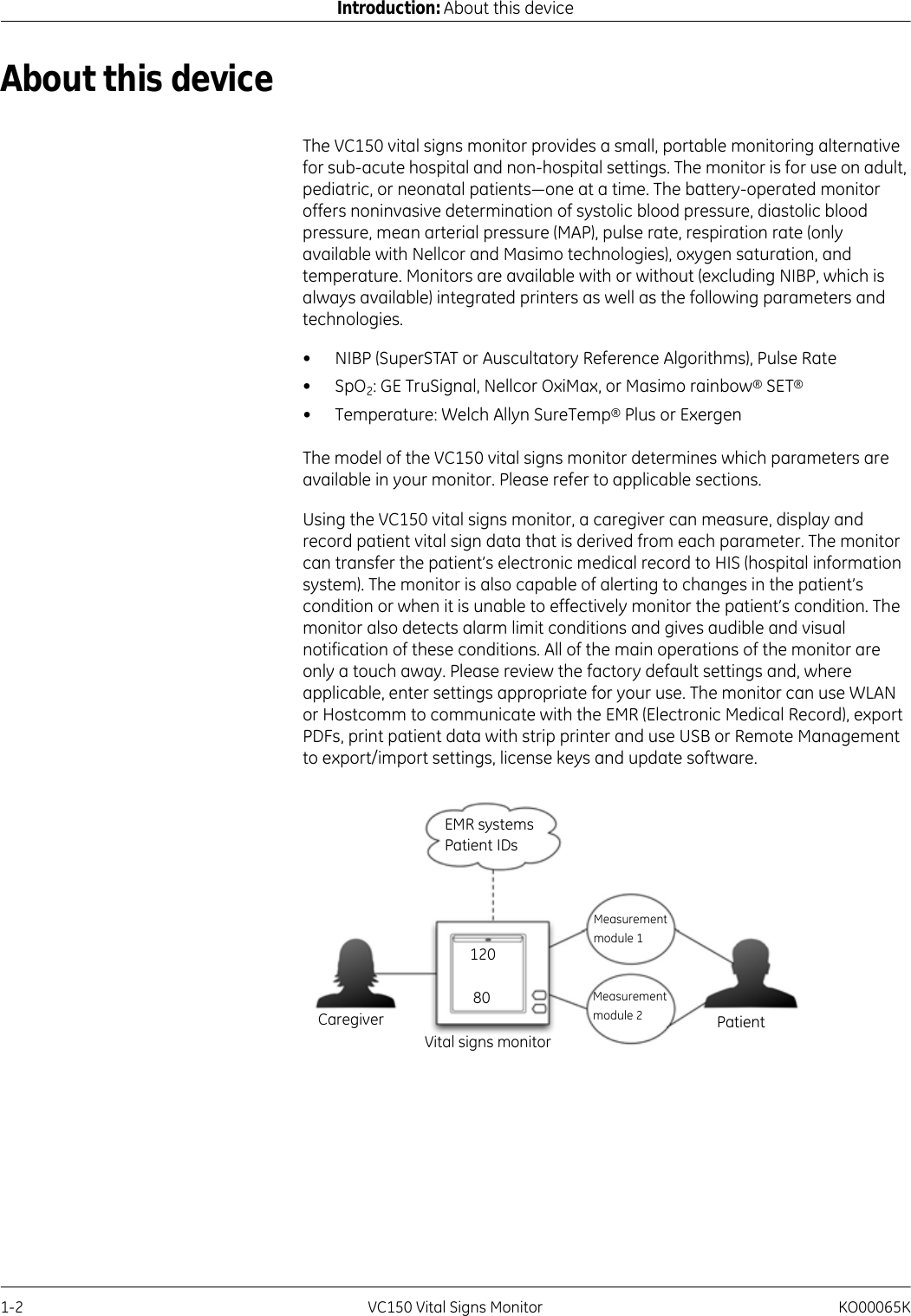
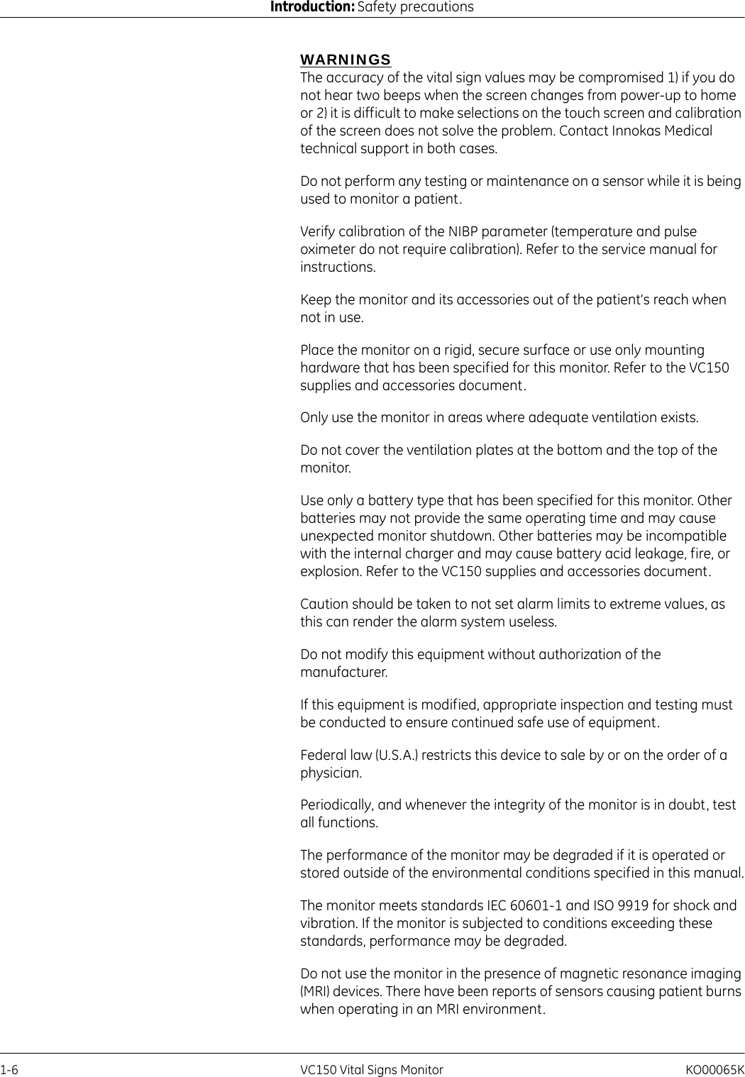
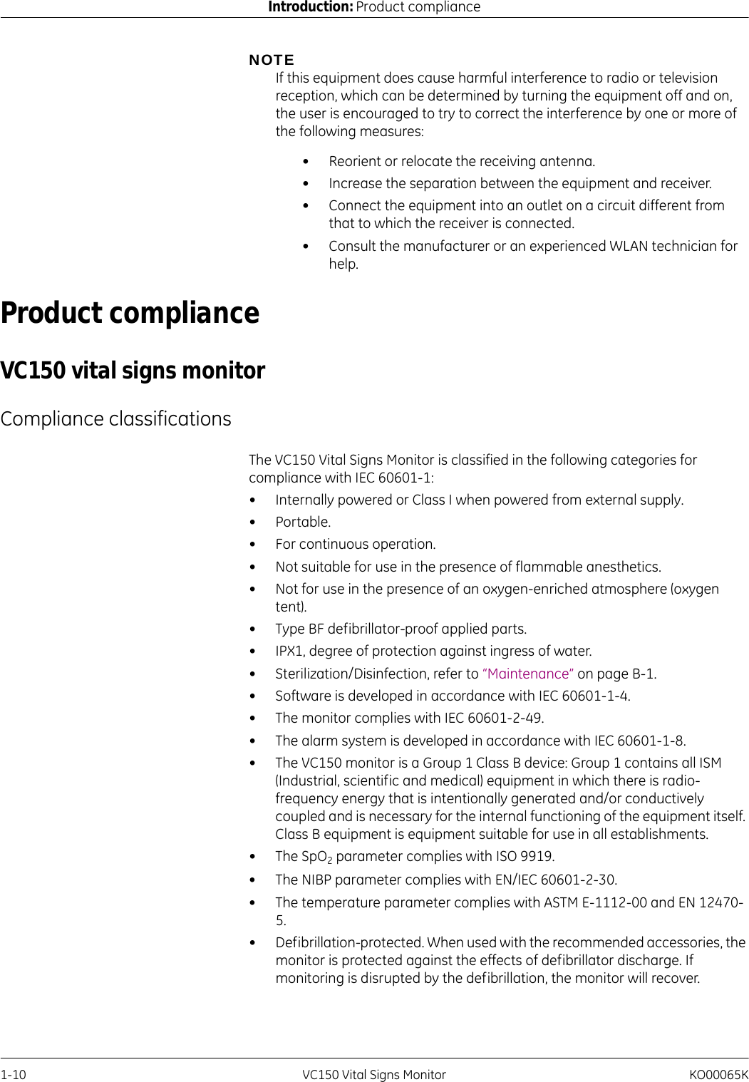
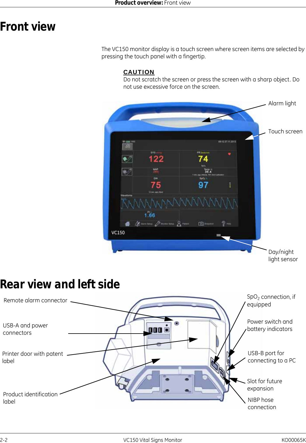
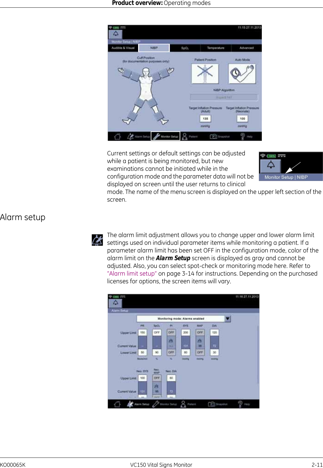
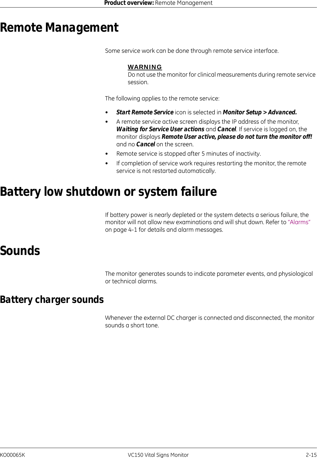
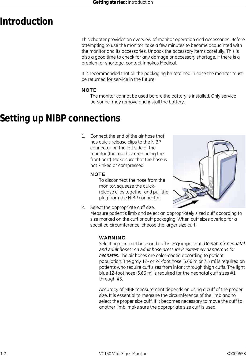
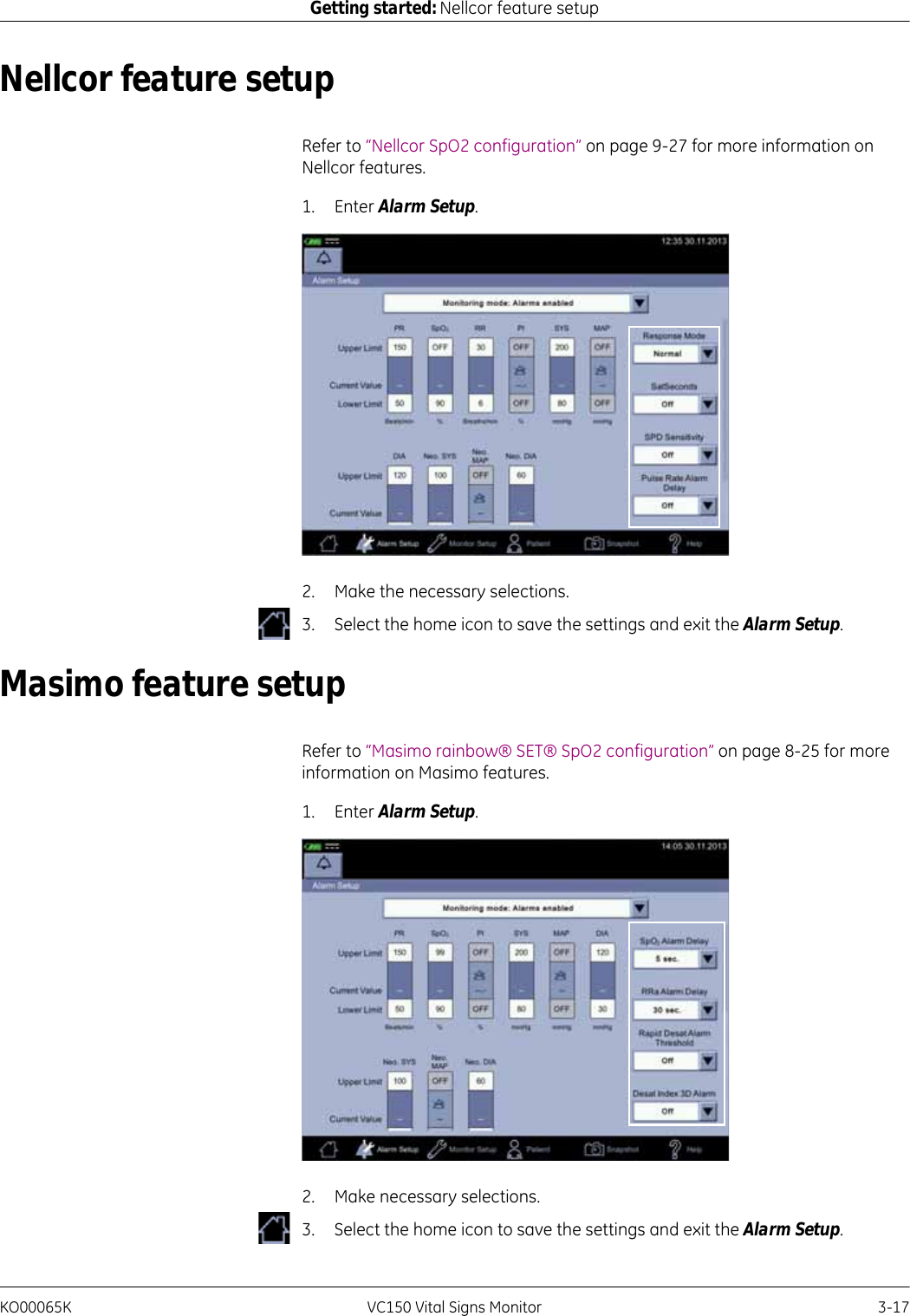
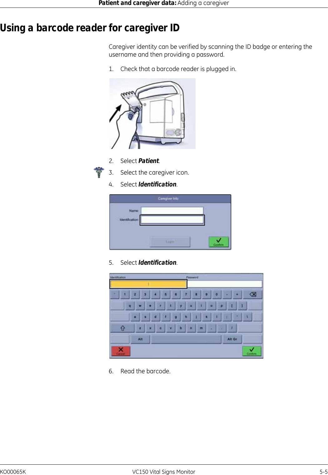
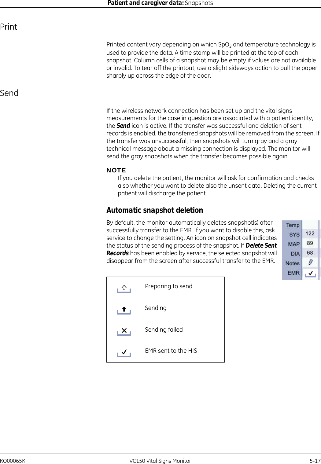
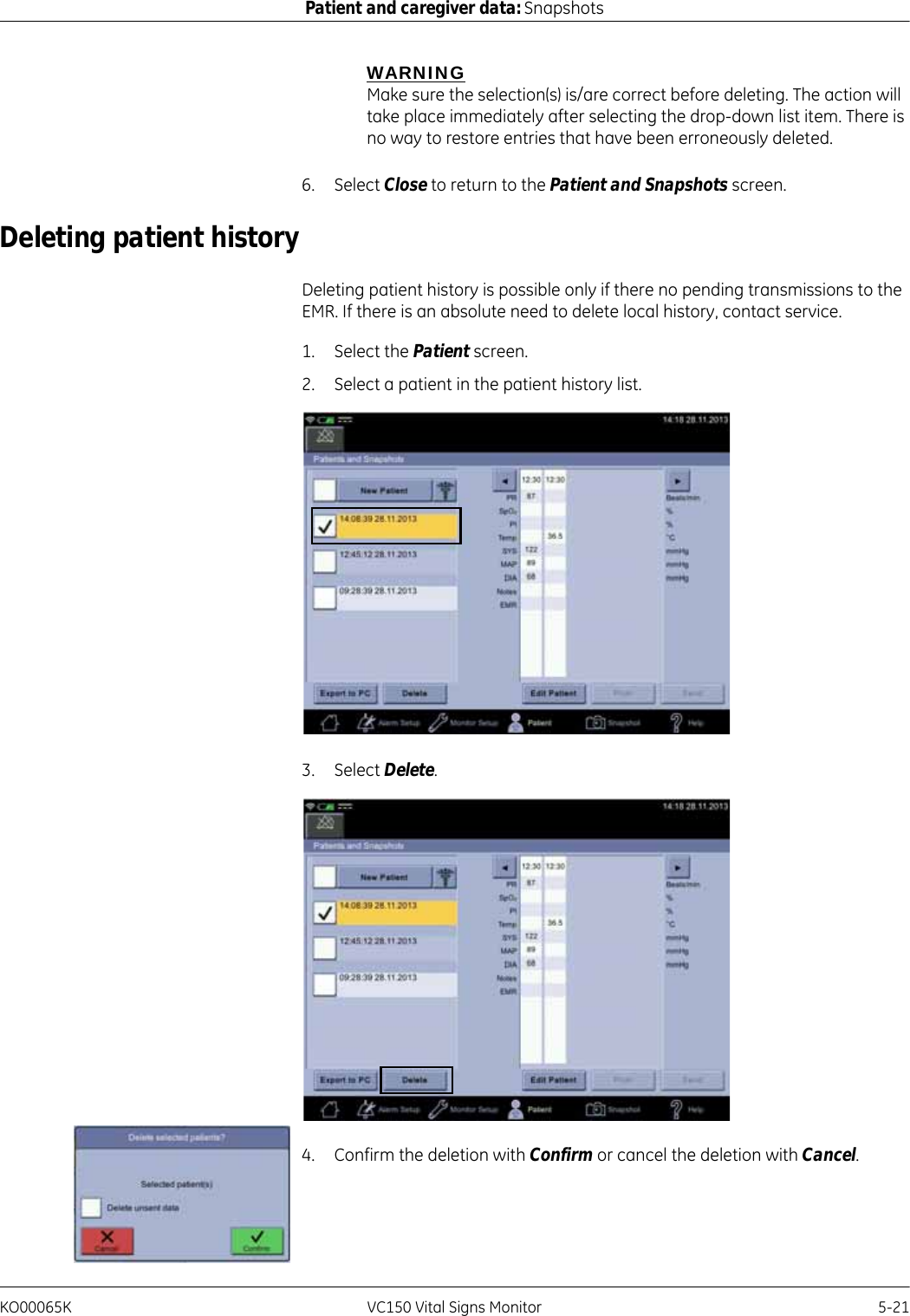
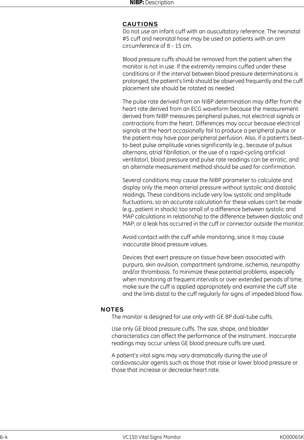
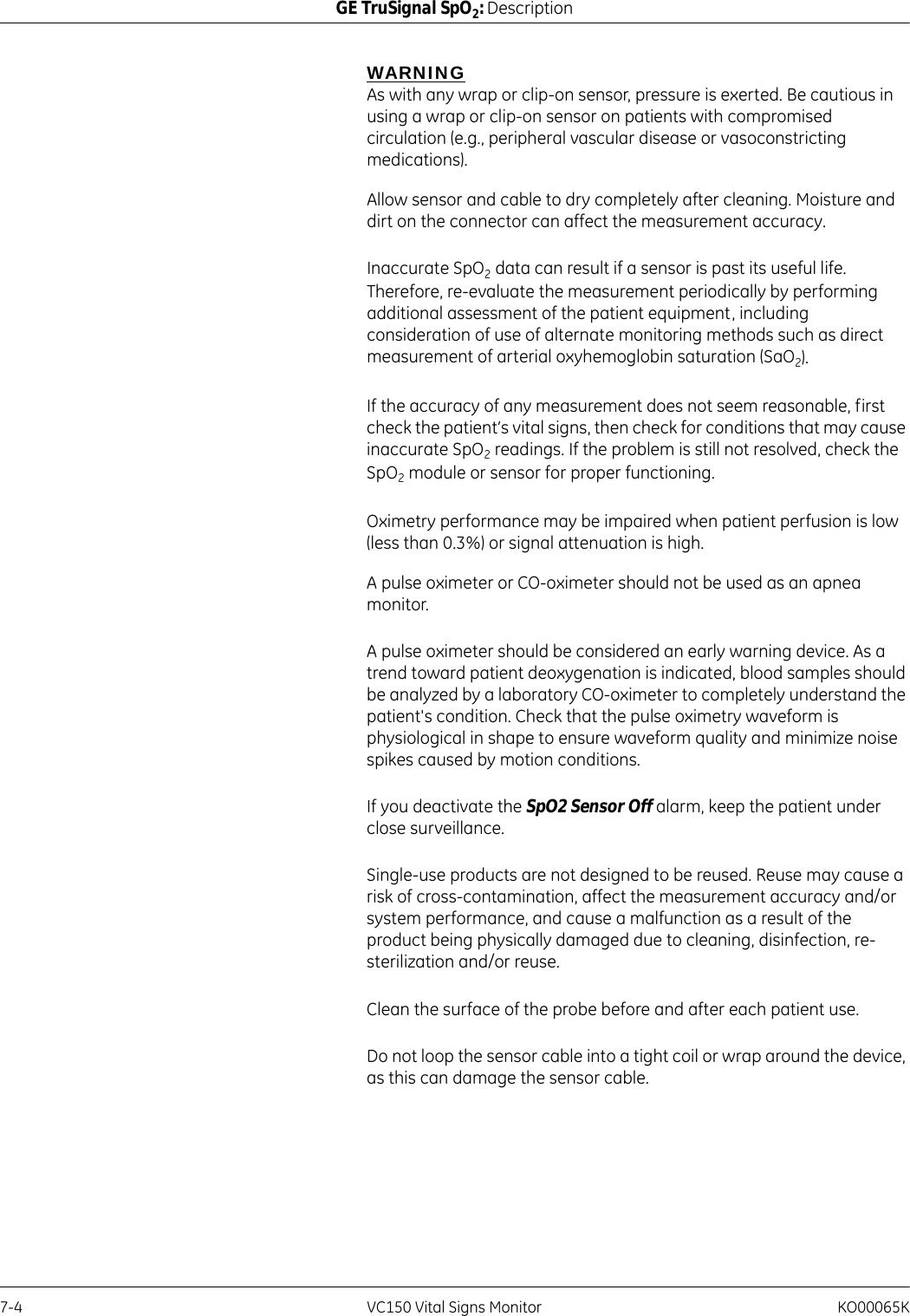
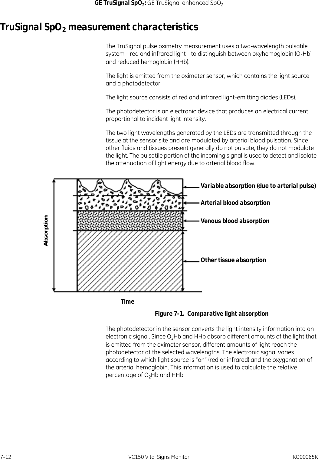
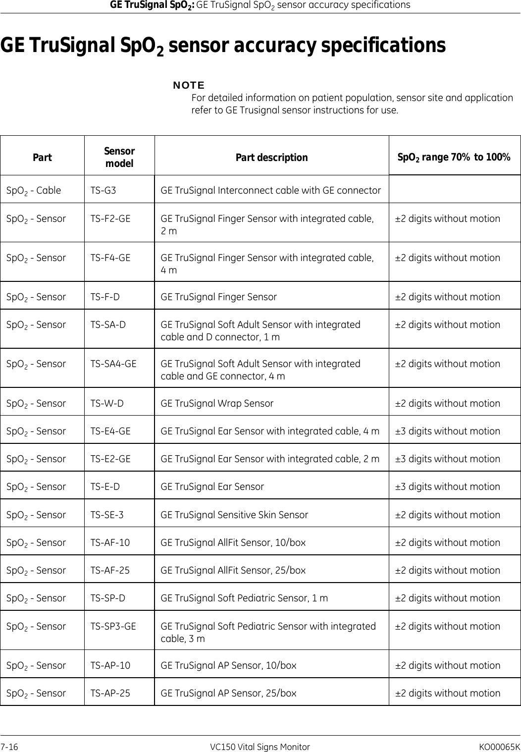
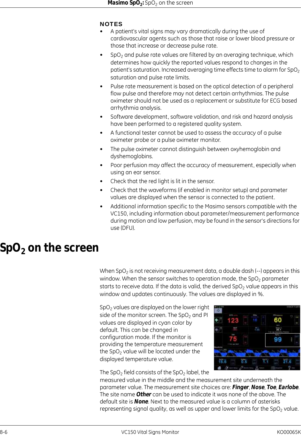
![KO00065K VC150 Vital Signs Monitor 8-23Masimo SpO2: Masimo rainbow® SET® SpO2 and special featuresrainbow Acoustic Monitoring (RAM) Technologyrainbow Acoustic Monitoring (RAM) continuously measures a patient’s respiration rate based on airflow sounds generated in the upper airway. The Acoustic Sensor translates airflow sounds generated in the upper airway to an electrical signal that can be processed to produce a respiration rate, measured as breaths per minute.Respiratory sounds include sounds related to respiration such as breath sounds (during inspiration and expiration), adventitious sounds, cough sounds, snoring sounds, sneezing sounds, and sounds from the respiratory muscles [1].These respiratory sounds often have different characteristics depending on the location of recording [2] and they originate in the large airways where air velocity and air turbulence induce vibration in the airway wall. These vibrations are transmitted, for example, through the lung tissue, thoracic wall and trachea to the surface where they may be heard with the aid of a stethoscope, a stethoscope, a microphone or more sophisticated devices.rainbow Acoustic Monitoring ArchitectureThe following figure illustrates how a respiratory sound produced by a patient can be turned into a numerical measurement that corresponds to a respiratory parameter.PatientThe generation of respiratory sounds is primarily related to turbulent respiratory airflow in upper airways. Sound pressure waves within the airway gas and airway wall motion contribute to the vibrations that reach the body surface and are recorded as respiratory sounds.Although the spectral shape of respiratory sounds varies widely from person to person, it is often reproducible within the same person, likely reflecting the strong influence of individual airway anatomy [2-6].PatientSignalSensorEnvelopeAcquisitionRRa EstimationSystemProcessingRespiratory airflow to soundSound to electrical signalElectrical signal to digital signalDigital signal to respiratory measurementDetection](https://usermanual.wiki/Innokas-Yhtyma/VC150/User-Guide-2418996-Page-191.png)
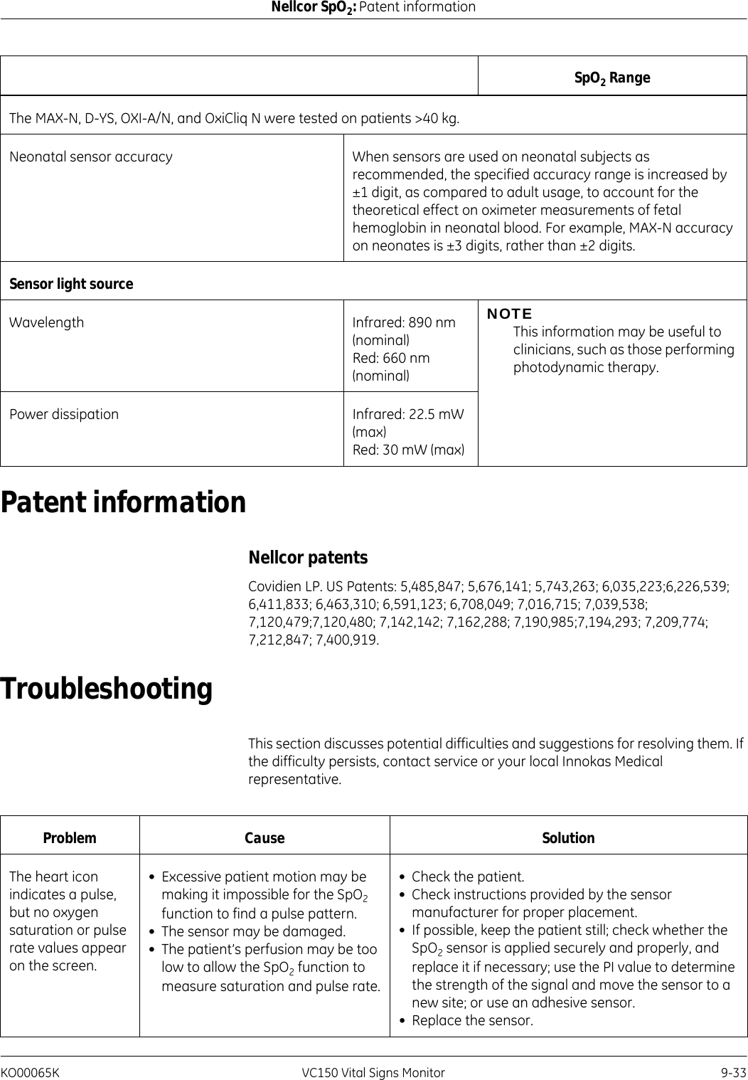
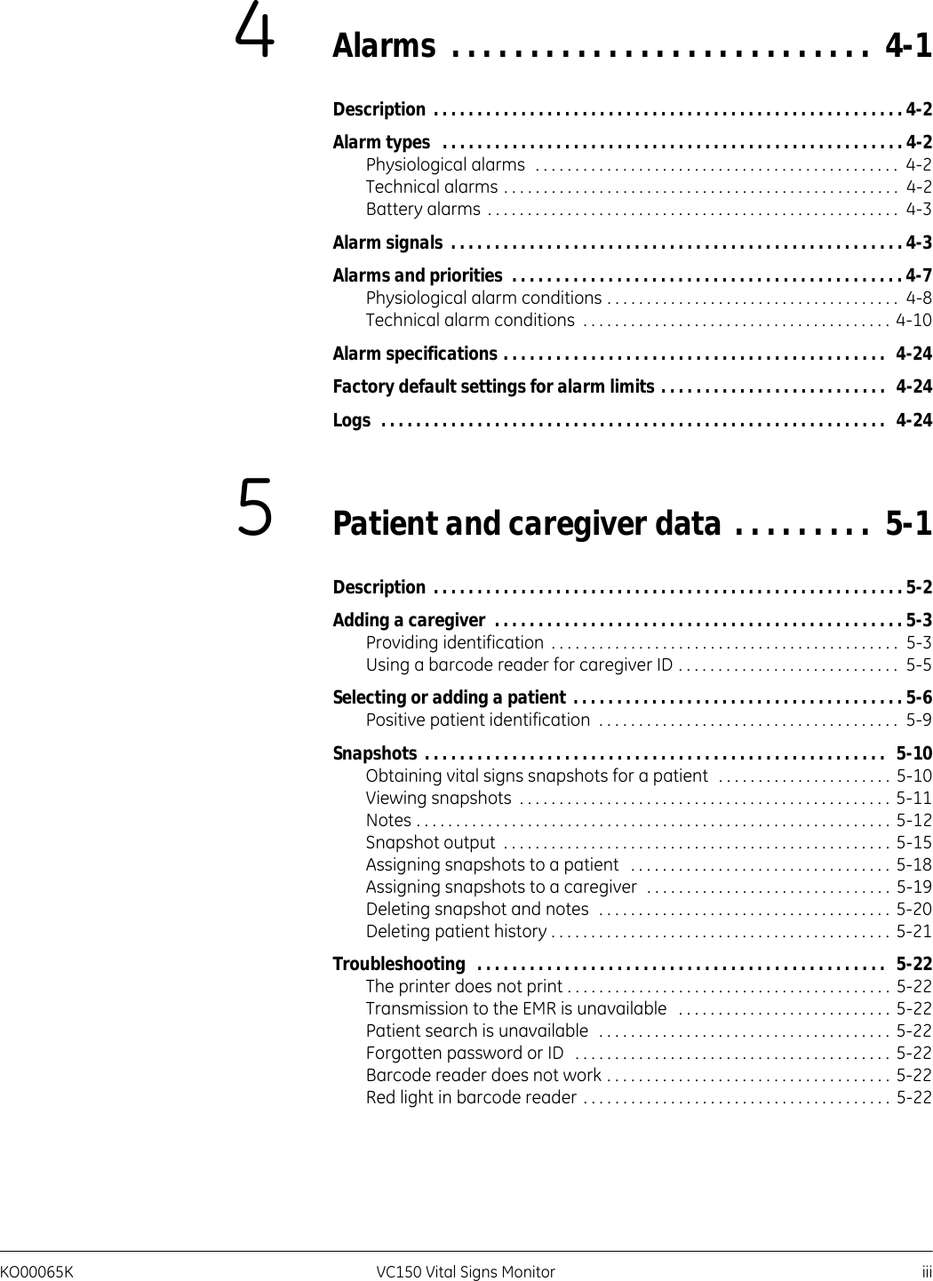
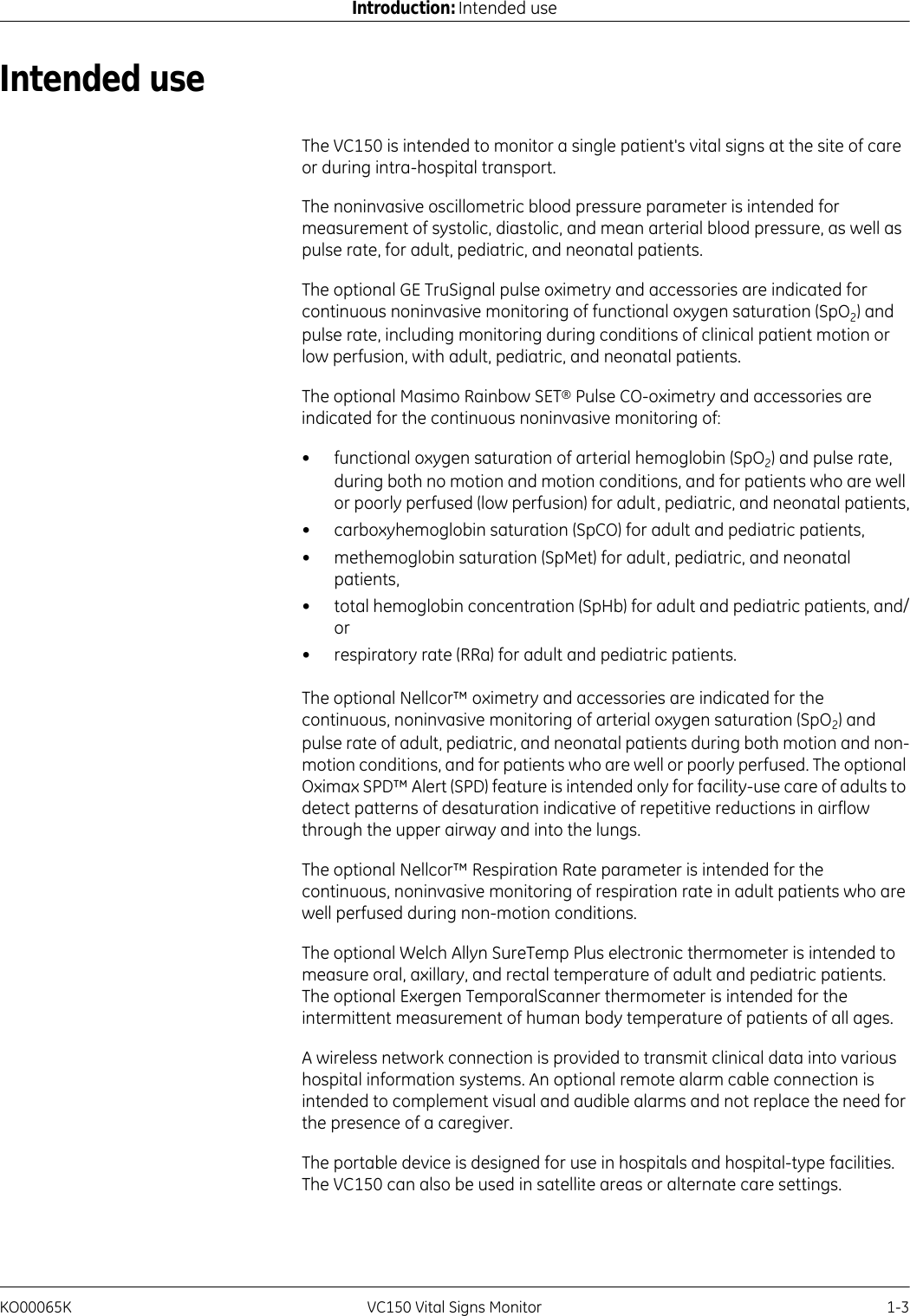
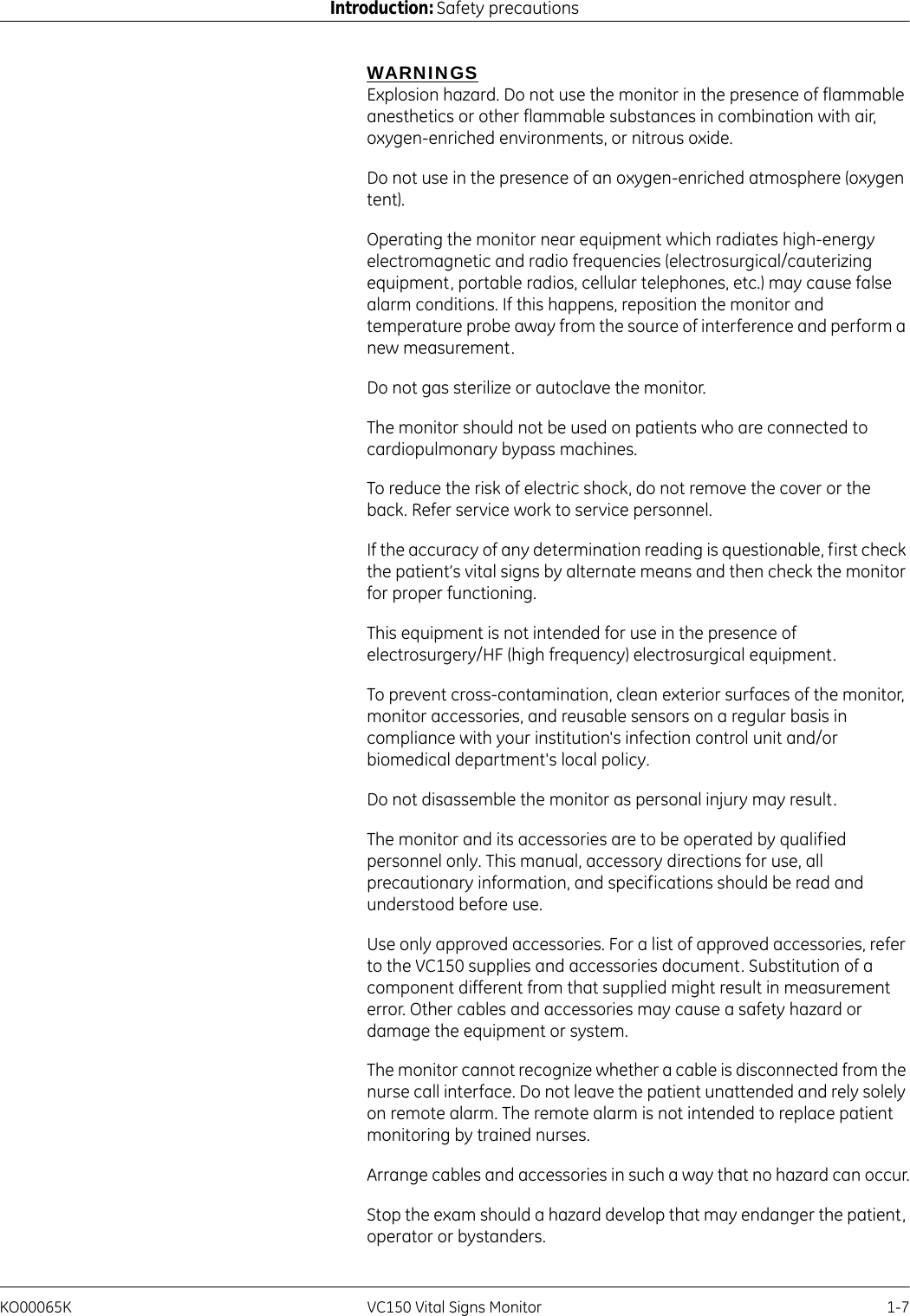
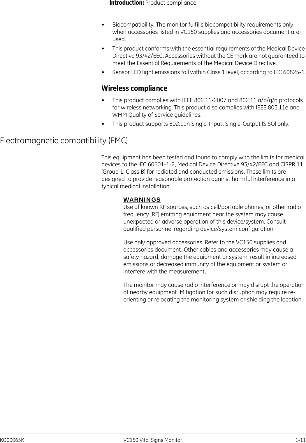
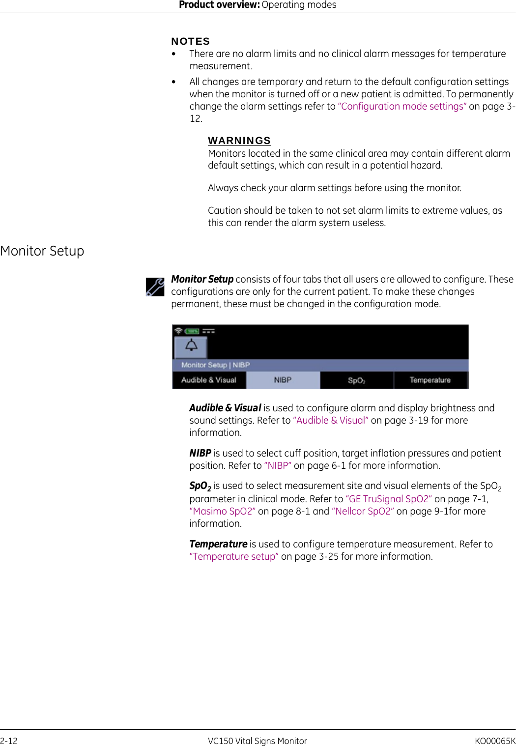
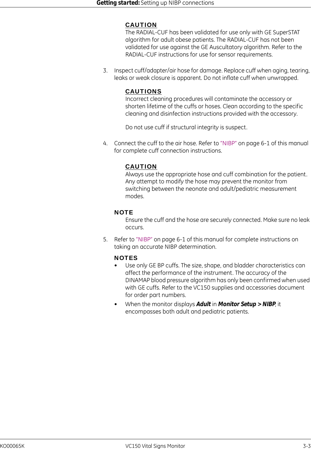
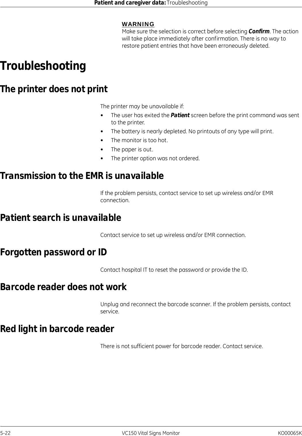
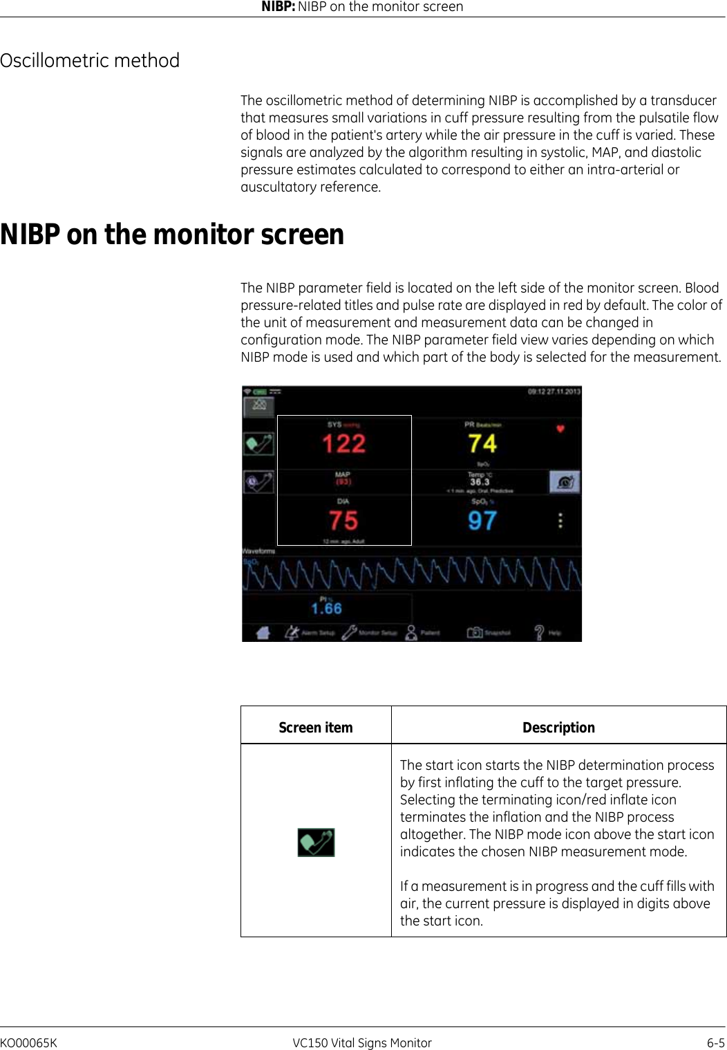
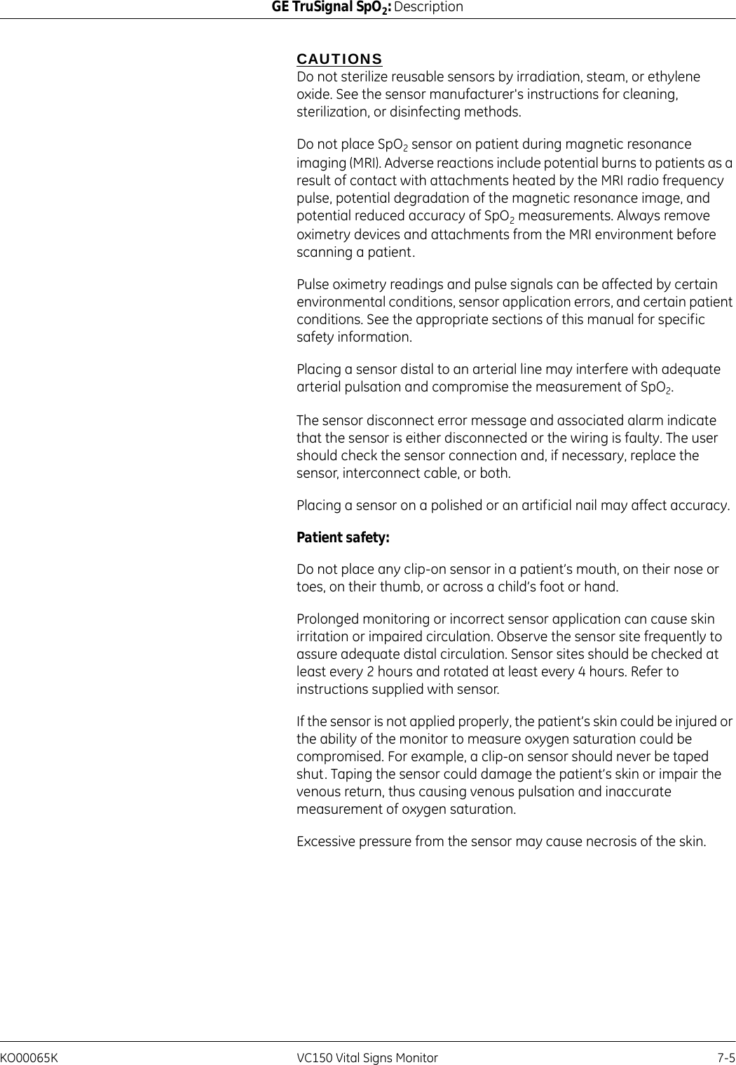
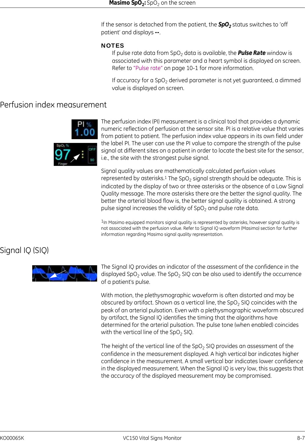
![8-24 VC150 Vital Signs Monitor KO00065KMasimo SpO2: Masimo rainbow® SET® SpO2 and special featuresSensorThe sensor captures respiratory sounds (and other biological sounds) much like a microphone does. When subjected to a mechanical strain, (e.g., surface vibrations generated during breathing), the sensor becomes electrically polarized.The degree of polarization is proportional to the applied strain. The output of the sensor is an electric signal that includes a sound signal that is modulated by inspiratory and expiratory phases of the respiratory cycle.Acquisition SystemThe acquisition system converts the electric signal provided by the sensor into a digital signal. This format allows the signal to be processed by a computing device.Signal ProcessingThe digital signal produced by the acquisition system is converted into a measurement that corresponds to the respiratory parameter of interest. As shown in the previous figure, this can be performed by, for example, determining the digital signal envelope or outline which in turn may be utilized to determine the respiratory rate. In this way, a real-time, continuous breath rate parameter can be obtained and displayed on a monitor which, in many cases, may be real-time and continuous.The respiratory cycle envelope signal processing principle is similar to methods that sample airway gasses and subsequently determine a respiratory rate.[1] A.R.A. Sovijärvi, F. Dalmasso, J. Vanderschool, L.P. Malmberg, G. Righini, S.A.T. Stoneman. Definition of terms for applications of respiratory sounds. Eur Respir Rev 2000; 10:77, 597-610.[2] Z. Moussavi. Fundamentals of respiratory sounds analysis. Synthesis lectures on biomedical engineering #8. Morgan & Claypool Publishers, 2006.[3] Olsen, et al. Mechanisms of lung sound generation. Semin Respir Med 1985; 6: 171-179.[4] Pastercamp H, Kraman SS, Wodicka GR. Respiratory sounds – Advances beyond the stethoscope. Am J Respir Crit Care Med 1977; 156: 974-987.[5] Gavriely N, Cugell DW. Airflow effects on amplitude and spectral content of normal breath sounds. J Appl Physiol 1996; 80: 5-13.[6] Gavrieli N, Palti Y, Alroy G. Spectral characteristics of normal breath sounds. J Appl Physiol 1981; 50: 307-314.](https://usermanual.wiki/Innokas-Yhtyma/VC150/User-Guide-2418996-Page-192.png)