Innokas Yhtyma VC150 Patient Monitor User Manual
Innokas Yhtyma Oy Patient Monitor
Operators Manual
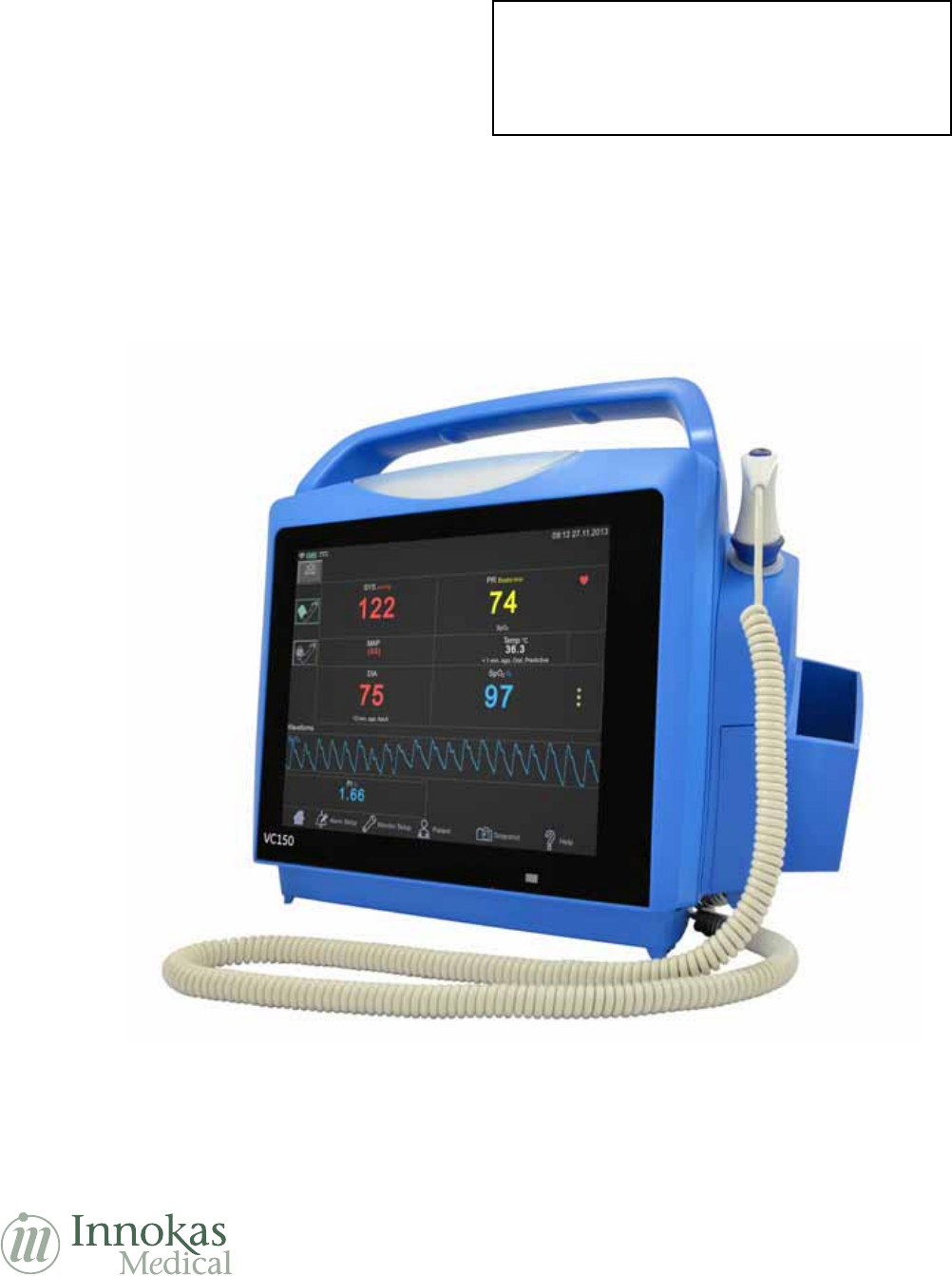
VC150 Vital Signs Monitor
Operator’s Manual
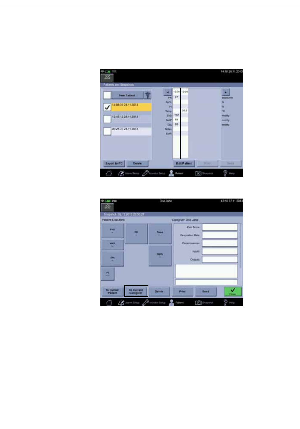
VC150 Vital Signs Monitor
English
KO00065K
© 2014 Innokas Medical
All rights reserved.
LOW RESOLUTION PDF
NOT FOR CUSTOMER PRINT!

T-2 VC150 Vital Signs Monitor KO00065K
30 September 2014
NOTE
The information in this manual applies to VC150 Vital Signs Monitor. Due to
continuing product innovation, specifications in this manual are subject to
change without notice.
Listed below are GE Medical Systems Information Technologies, Inc. trademarks.
All other trademarks contained herein are the property of their respective
owners.
GE TruSignal is the property of GE Medical Systems Information Technologies,
Inc., a division of General Electric Corporation. All other product and company
names are the property of their respective owners.
Description of NIBP algorithm © GE Medical Systems Information Technologies,
Inc., reproduced by permission.
DINAMAP, DURA-CUF, SOFT-CUF Blood Pressure Cuffs, and SuperSTAT are
trademarks of GE Medical Systems Information Technologies, Inc.
Welch Allyn® and SureTemp® Plus are registered trademarks of Welch Allyn, Inc.
Exergen and TAT-5000S -USB are trademarks of Exergen Corporation.
Betadine® is a registered trademark of Purdue-Frederick.
Masimo rainbow® SET®, LNOP, LNCS and Signal IQ are registered trademarks of
Masimo Corporation. Possession or purchase of this device does not convey any
express or implied license to use the device with unauthorized sensors or cables
which would, alone or in combination with this device, fall within the scope of
one or more of the patents relating to this device.
Nellcor, OxiMax, C-LOCK and SatSeconds are trademarks of Covidien.
Innokas Medical is a subsidiary of Innokas Yhtymä Oy.

KO00065K VC150 Vital Signs Monitor i
Contents
1Introduction . . . . . . . . . . . . . . . . . . . . . . 1-1
About this device . . . . . . . . . . . . . . . . . . . . . . . . . . . . . . . . . . . . . . . . . . . . . . . . . 1-2
Intended use . . . . . . . . . . . . . . . . . . . . . . . . . . . . . . . . . . . . . . . . . . . . . . . . . . . . 1-3
Contraindications . . . . . . . . . . . . . . . . . . . . . . . . . . . . . . . . . . . . . . . . . . . . . . . . 1-4
Dangers, warnings, cautions, and notes . . . . . . . . . . . . . . . . . . . . . . . . . . . . 1-4
Safety precautions . . . . . . . . . . . . . . . . . . . . . . . . . . . . . . . . . . . . . . . . . . . . . . . 1-5
Product compliance . . . . . . . . . . . . . . . . . . . . . . . . . . . . . . . . . . . . . . . . . . . . 1-10
VC150 vital signs monitor . . . . . . . . . . . . . . . . . . . . . . . . . . . . . . . . . . . . . . . . . 1-10
Exergen temporal scanner . . . . . . . . . . . . . . . . . . . . . . . . . . . . . . . . . . . . . . . 1-12
Monitor symbols . . . . . . . . . . . . . . . . . . . . . . . . . . . . . . . . . . . . . . . . . . . . . . . 1-13
About this manual . . . . . . . . . . . . . . . . . . . . . . . . . . . . . . . . . . . . . . . . . . . . . 1-16
Service requirements . . . . . . . . . . . . . . . . . . . . . . . . . . . . . . . . . . . . . . . . . . . . . 1-17
2Product overview . . . . . . . . . . . . . . . . . 2-1
Front view . . . . . . . . . . . . . . . . . . . . . . . . . . . . . . . . . . . . . . . . . . . . . . . . . . . . . . . 2-2
Rear view and left side . . . . . . . . . . . . . . . . . . . . . . . . . . . . . . . . . . . . . . . . . . . . 2-2
Right side . . . . . . . . . . . . . . . . . . . . . . . . . . . . . . . . . . . . . . . . . . . . . . . . . . . . . . . 2-3
User interface and connections . . . . . . . . . . . . . . . . . . . . . . . . . . . . . . . . . . . . 2-4
Operating modes . . . . . . . . . . . . . . . . . . . . . . . . . . . . . . . . . . . . . . . . . . . . . . . . 2-9
Clinical mode . . . . . . . . . . . . . . . . . . . . . . . . . . . . . . . . . . . . . . . . . . . . . . . . . . . . 2-10
Monitor configuration . . . . . . . . . . . . . . . . . . . . . . . . . . . . . . . . . . . . . . . . . . . . 2-10
Printout . . . . . . . . . . . . . . . . . . . . . . . . . . . . . . . . . . . . . . . . . . . . . . . . . . . . . . . 2-14
Remote Management . . . . . . . . . . . . . . . . . . . . . . . . . . . . . . . . . . . . . . . . . . . 2-15
Battery low shutdown or system failure . . . . . . . . . . . . . . . . . . . . . . . . . . 2-15
Sounds . . . . . . . . . . . . . . . . . . . . . . . . . . . . . . . . . . . . . . . . . . . . . . . . . . . . . . . . 2-15
Battery charger sounds . . . . . . . . . . . . . . . . . . . . . . . . . . . . . . . . . . . . . . . . . . 2-15
Essential performance . . . . . . . . . . . . . . . . . . . . . . . . . . . . . . . . . . . . . . . . . . 2-16
Product specifications . . . . . . . . . . . . . . . . . . . . . . . . . . . . . . . . . . . . . . . . . . 2-19
Printer specifications . . . . . . . . . . . . . . . . . . . . . . . . . . . . . . . . . . . . . . . . . . . 2-21
Connectivity specifications . . . . . . . . . . . . . . . . . . . . . . . . . . . . . . . . . . . . . . 2-21
Open source software notice . . . . . . . . . . . . . . . . . . . . . . . . . . . . . . . . . . . . 2-23

KO00065K VC150 Vital Signs Monitor ii
3Getting started . . . . . . . . . . . . . . . . . . . 3-1
Introduction . . . . . . . . . . . . . . . . . . . . . . . . . . . . . . . . . . . . . . . . . . . . . . . . . . . . . 3-2
Setting up NIBP connections . . . . . . . . . . . . . . . . . . . . . . . . . . . . . . . . . . . . . . 3-2
Setting up SpO2 connections . . . . . . . . . . . . . . . . . . . . . . . . . . . . . . . . . . . . . . 3-4
Setting up temperature connection . . . . . . . . . . . . . . . . . . . . . . . . . . . . . . . . 3-4
Welch Allyn (optional) . . . . . . . . . . . . . . . . . . . . . . . . . . . . . . . . . . . . . . . . . . . . . 3-4
Connecting USB accessories . . . . . . . . . . . . . . . . . . . . . . . . . . . . . . . . . . . . . . 3-6
Installation/replacement of printer paper . . . . . . . . . . . . . . . . . . . . . . . . . . 3-6
Paper storage . . . . . . . . . . . . . . . . . . . . . . . . . . . . . . . . . . . . . . . . . . . . . . . . . . . . . 3-7
Electrical connection . . . . . . . . . . . . . . . . . . . . . . . . . . . . . . . . . . . . . . . . . . . . . 3-7
Power sources . . . . . . . . . . . . . . . . . . . . . . . . . . . . . . . . . . . . . . . . . . . . . . . . . . . . 3-7
Monitor on/off . . . . . . . . . . . . . . . . . . . . . . . . . . . . . . . . . . . . . . . . . . . . . . . . . . . 3-8
Touch screen recalibration . . . . . . . . . . . . . . . . . . . . . . . . . . . . . . . . . . . . . . . . 3-9
Standby . . . . . . . . . . . . . . . . . . . . . . . . . . . . . . . . . . . . . . . . . . . . . . . . . . . . . . . . . 3-10
Monitor standby . . . . . . . . . . . . . . . . . . . . . . . . . . . . . . . . . . . . . . . . . . . . . . . . . 3-10
Turning the monitor off . . . . . . . . . . . . . . . . . . . . . . . . . . . . . . . . . . . . . . . . . . . 3-11
Summary . . . . . . . . . . . . . . . . . . . . . . . . . . . . . . . . . . . . . . . . . . . . . . . . . . . . . . . . 3-11
Procedure for testing alarms . . . . . . . . . . . . . . . . . . . . . . . . . . . . . . . . . . . . 3-11
Configuration mode settings . . . . . . . . . . . . . . . . . . . . . . . . . . . . . . . . . . . . 3-12
Using the numeric keypad . . . . . . . . . . . . . . . . . . . . . . . . . . . . . . . . . . . . . . 3-12
Icons on the monitor . . . . . . . . . . . . . . . . . . . . . . . . . . . . . . . . . . . . . . . . . . . 3-13
Using the home icon . . . . . . . . . . . . . . . . . . . . . . . . . . . . . . . . . . . . . . . . . . . . . 3-13
Alarm limit setup . . . . . . . . . . . . . . . . . . . . . . . . . . . . . . . . . . . . . . . . . . . . . . . 3-14
Changing limits for a single parameter box . . . . . . . . . . . . . . . . . . . . . . . . 3-15
Changing multiple alarm limits . . . . . . . . . . . . . . . . . . . . . . . . . . . . . . . . . . . 3-16
Nellcor feature setup . . . . . . . . . . . . . . . . . . . . . . . . . . . . . . . . . . . . . . . . . . . 3-17
Masimo feature setup . . . . . . . . . . . . . . . . . . . . . . . . . . . . . . . . . . . . . . . . . . 3-17
Monitor setup . . . . . . . . . . . . . . . . . . . . . . . . . . . . . . . . . . . . . . . . . . . . . . . . . . 3-18
Shortcut to setup screens . . . . . . . . . . . . . . . . . . . . . . . . . . . . . . . . . . . . . . . . 3-18
Menu selection for setup screens . . . . . . . . . . . . . . . . . . . . . . . . . . . . . . . . 3-19
Audible & Visual . . . . . . . . . . . . . . . . . . . . . . . . . . . . . . . . . . . . . . . . . . . . . . . . . . 3-19
NIBP setup . . . . . . . . . . . . . . . . . . . . . . . . . . . . . . . . . . . . . . . . . . . . . . . . . . . . . . . 3-21
SpO2 setup . . . . . . . . . . . . . . . . . . . . . . . . . . . . . . . . . . . . . . . . . . . . . . . . . . . . . . 3-23
Temperature setup . . . . . . . . . . . . . . . . . . . . . . . . . . . . . . . . . . . . . . . . . . . . . . . 3-25
Advanced . . . . . . . . . . . . . . . . . . . . . . . . . . . . . . . . . . . . . . . . . . . . . . . . . . . . . . . . 3-25
Patient . . . . . . . . . . . . . . . . . . . . . . . . . . . . . . . . . . . . . . . . . . . . . . . . . . . . . . . . 3-26
Patient identification . . . . . . . . . . . . . . . . . . . . . . . . . . . . . . . . . . . . . . . . . . . . . 3-26
Snapshot . . . . . . . . . . . . . . . . . . . . . . . . . . . . . . . . . . . . . . . . . . . . . . . . . . . . . . 3-26
Help . . . . . . . . . . . . . . . . . . . . . . . . . . . . . . . . . . . . . . . . . . . . . . . . . . . . . . . . . . 3-27

KO00065K VC150 Vital Signs Monitor iii
4Alarms . . . . . . . . . . . . . . . . . . . . . . . . . . . 4-1
Description . . . . . . . . . . . . . . . . . . . . . . . . . . . . . . . . . . . . . . . . . . . . . . . . . . . . . . 4-2
Alarm types . . . . . . . . . . . . . . . . . . . . . . . . . . . . . . . . . . . . . . . . . . . . . . . . . . . . . 4-2
Physiological alarms . . . . . . . . . . . . . . . . . . . . . . . . . . . . . . . . . . . . . . . . . . . . . . 4-2
Technical alarms . . . . . . . . . . . . . . . . . . . . . . . . . . . . . . . . . . . . . . . . . . . . . . . . . . 4-2
Battery alarms . . . . . . . . . . . . . . . . . . . . . . . . . . . . . . . . . . . . . . . . . . . . . . . . . . . . 4-3
Alarm signals . . . . . . . . . . . . . . . . . . . . . . . . . . . . . . . . . . . . . . . . . . . . . . . . . . . . 4-3
Alarms and priorities . . . . . . . . . . . . . . . . . . . . . . . . . . . . . . . . . . . . . . . . . . . . . 4-7
Physiological alarm conditions . . . . . . . . . . . . . . . . . . . . . . . . . . . . . . . . . . . . . 4-8
Technical alarm conditions . . . . . . . . . . . . . . . . . . . . . . . . . . . . . . . . . . . . . . . 4-10
Alarm specifications . . . . . . . . . . . . . . . . . . . . . . . . . . . . . . . . . . . . . . . . . . . . 4-24
Factory default settings for alarm limits . . . . . . . . . . . . . . . . . . . . . . . . . . 4-24
Logs . . . . . . . . . . . . . . . . . . . . . . . . . . . . . . . . . . . . . . . . . . . . . . . . . . . . . . . . . . 4-24
5Patient and caregiver data . . . . . . . . . 5-1
Description . . . . . . . . . . . . . . . . . . . . . . . . . . . . . . . . . . . . . . . . . . . . . . . . . . . . . . 5-2
Adding a caregiver . . . . . . . . . . . . . . . . . . . . . . . . . . . . . . . . . . . . . . . . . . . . . . . 5-3
Providing identification . . . . . . . . . . . . . . . . . . . . . . . . . . . . . . . . . . . . . . . . . . . . 5-3
Using a barcode reader for caregiver ID . . . . . . . . . . . . . . . . . . . . . . . . . . . . 5-5
Selecting or adding a patient . . . . . . . . . . . . . . . . . . . . . . . . . . . . . . . . . . . . . . 5-6
Positive patient identification . . . . . . . . . . . . . . . . . . . . . . . . . . . . . . . . . . . . . . 5-9
Snapshots . . . . . . . . . . . . . . . . . . . . . . . . . . . . . . . . . . . . . . . . . . . . . . . . . . . . . 5-10
Obtaining vital signs snapshots for a patient . . . . . . . . . . . . . . . . . . . . . . 5-10
Viewing snapshots . . . . . . . . . . . . . . . . . . . . . . . . . . . . . . . . . . . . . . . . . . . . . . . 5-11
Notes . . . . . . . . . . . . . . . . . . . . . . . . . . . . . . . . . . . . . . . . . . . . . . . . . . . . . . . . . . . . 5-12
Snapshot output . . . . . . . . . . . . . . . . . . . . . . . . . . . . . . . . . . . . . . . . . . . . . . . . . 5-15
Assigning snapshots to a patient . . . . . . . . . . . . . . . . . . . . . . . . . . . . . . . . . 5-18
Assigning snapshots to a caregiver . . . . . . . . . . . . . . . . . . . . . . . . . . . . . . . 5-19
Deleting snapshot and notes . . . . . . . . . . . . . . . . . . . . . . . . . . . . . . . . . . . . . 5-20
Deleting patient history . . . . . . . . . . . . . . . . . . . . . . . . . . . . . . . . . . . . . . . . . . . 5-21
Troubleshooting . . . . . . . . . . . . . . . . . . . . . . . . . . . . . . . . . . . . . . . . . . . . . . . 5-22
The printer does not print . . . . . . . . . . . . . . . . . . . . . . . . . . . . . . . . . . . . . . . . . 5-22
Transmission to the EMR is unavailable . . . . . . . . . . . . . . . . . . . . . . . . . . . 5-22
Patient search is unavailable . . . . . . . . . . . . . . . . . . . . . . . . . . . . . . . . . . . . . 5-22
Forgotten password or ID . . . . . . . . . . . . . . . . . . . . . . . . . . . . . . . . . . . . . . . . 5-22
Barcode reader does not work . . . . . . . . . . . . . . . . . . . . . . . . . . . . . . . . . . . . 5-22
Red light in barcode reader . . . . . . . . . . . . . . . . . . . . . . . . . . . . . . . . . . . . . . . 5-22

KO00065K VC150 Vital Signs Monitor iv
6NIBP . . . . . . . . . . . . . . . . . . . . . . . . . . . . . 6-1
Description . . . . . . . . . . . . . . . . . . . . . . . . . . . . . . . . . . . . . . . . . . . . . . . . . . . . . . 6-2
Differences in intra-arterial and auscultatory references . . . . . . . . . . . . 6-3
NIBP on the monitor screen . . . . . . . . . . . . . . . . . . . . . . . . . . . . . . . . . . . . . . . 6-5
Alarms associated with NIBP . . . . . . . . . . . . . . . . . . . . . . . . . . . . . . . . . . . . . . 6-7
NIBP modes of operation . . . . . . . . . . . . . . . . . . . . . . . . . . . . . . . . . . . . . . . . . . 6-8
Adaptive target inflation pressure . . . . . . . . . . . . . . . . . . . . . . . . . . . . . . . . . . 6-8
Single NIBP determinations . . . . . . . . . . . . . . . . . . . . . . . . . . . . . . . . . . . . . . . . 6-9
STAT NIBP determinations . . . . . . . . . . . . . . . . . . . . . . . . . . . . . . . . . . . . . . . . . 6-9
Auto cycle determinations . . . . . . . . . . . . . . . . . . . . . . . . . . . . . . . . . . . . . . . . 6-10
Profile cycle determinations . . . . . . . . . . . . . . . . . . . . . . . . . . . . . . . . . . . . . . 6-11
Venous return for cycle and profile . . . . . . . . . . . . . . . . . . . . . . . . . . . . . . . . 6-11
NIBP alarm limits . . . . . . . . . . . . . . . . . . . . . . . . . . . . . . . . . . . . . . . . . . . . . . . 6-12
NIBP settings . . . . . . . . . . . . . . . . . . . . . . . . . . . . . . . . . . . . . . . . . . . . . . . . . . 6-12
Taking NIBP measurements . . . . . . . . . . . . . . . . . . . . . . . . . . . . . . . . . . . . . 6-12
Procedure . . . . . . . . . . . . . . . . . . . . . . . . . . . . . . . . . . . . . . . . . . . . . . . . . . . . . . . 6-12
Taking NIBP measurements on different patients . . . . . . . . . . . . . . . . . . 6-16
Alarms . . . . . . . . . . . . . . . . . . . . . . . . . . . . . . . . . . . . . . . . . . . . . . . . . . . . . . . . 6-17
NIBP specifications . . . . . . . . . . . . . . . . . . . . . . . . . . . . . . . . . . . . . . . . . . . . . 6-17
NIBP troubleshooting . . . . . . . . . . . . . . . . . . . . . . . . . . . . . . . . . . . . . . . . . . . 6-18
Overpressure . . . . . . . . . . . . . . . . . . . . . . . . . . . . . . . . . . . . . . . . . . . . . . . . . . . . 6-18
Increase in determination time . . . . . . . . . . . . . . . . . . . . . . . . . . . . . . . . . . . 6-18
No determination . . . . . . . . . . . . . . . . . . . . . . . . . . . . . . . . . . . . . . . . . . . . . . . . 6-19
7GE TruSignal SpO2 . . . . . . . . . . . . . . . . . . . . . . . . . 7-1
Description . . . . . . . . . . . . . . . . . . . . . . . . . . . . . . . . . . . . . . . . . . . . . . . . . . . . . . 7-2
SpO2 safety . . . . . . . . . . . . . . . . . . . . . . . . . . . . . . . . . . . . . . . . . . . . . . . . . . . . . . . 7-3
SpO2 on the screen . . . . . . . . . . . . . . . . . . . . . . . . . . . . . . . . . . . . . . . . . . . . . . . 7-7
Changing the SpO2 alarm limits . . . . . . . . . . . . . . . . . . . . . . . . . . . . . . . . . . . . 7-8
SpO2 procedure . . . . . . . . . . . . . . . . . . . . . . . . . . . . . . . . . . . . . . . . . . . . . . . . . . 7-9
SpO2 sounds . . . . . . . . . . . . . . . . . . . . . . . . . . . . . . . . . . . . . . . . . . . . . . . . . . . 7-10
Alarms . . . . . . . . . . . . . . . . . . . . . . . . . . . . . . . . . . . . . . . . . . . . . . . . . . . . . . . . 7-10
Alarm timer . . . . . . . . . . . . . . . . . . . . . . . . . . . . . . . . . . . . . . . . . . . . . . . . . . . . . . 7-10
TruSignal compatible accessories . . . . . . . . . . . . . . . . . . . . . . . . . . . . . . . . 7-11
GE TruSignal enhanced SpO2 . . . . . . . . . . . . . . . . . . . . . . . . . . . . . . . . . . . . . . . . . . . . . . . . . . . . 7-11
TruSignal SpO2 measurement characteristics . . . . . . . . . . . . . . . . . . . . . . 7-12
Calibration . . . . . . . . . . . . . . . . . . . . . . . . . . . . . . . . . . . . . . . . . . . . . . . . . . . . . . . 7-13
GE TruSignal SpO2 configuration . . . . . . . . . . . . . . . . . . . . . . . . . . . . . . . . . . 7-14
GE TruSignal SpO2 default settings . . . . . . . . . . . . . . . . . . . . . . . . . . . . . . . 7-14

KO00065K VC150 Vital Signs Monitor v
GE TruSignal SpO2 specifications . . . . . . . . . . . . . . . . . . . . . . . . . . . . . . . . 7-14
GE TruSignal SpO2 sensor accuracy specifications . . . . . . . . . . . . . . . . . 7-16
Troubleshooting . . . . . . . . . . . . . . . . . . . . . . . . . . . . . . . . . . . . . . . . . . . . . . . 7-18
8Masimo SpO2 . . . . . . . . . . . . . . . . . . . . . . . . . . . . . . . 8-1
Description . . . . . . . . . . . . . . . . . . . . . . . . . . . . . . . . . . . . . . . . . . . . . . . . . . . . . . 8-2
SpO2 safety . . . . . . . . . . . . . . . . . . . . . . . . . . . . . . . . . . . . . . . . . . . . . . . . . . . . . . . 8-3
SpO2 on the screen . . . . . . . . . . . . . . . . . . . . . . . . . . . . . . . . . . . . . . . . . . . . . . . 8-6
Changing the SpO2 alarm limits . . . . . . . . . . . . . . . . . . . . . . . . . . . . . . . . . . . . 8-8
SpO2 procedure . . . . . . . . . . . . . . . . . . . . . . . . . . . . . . . . . . . . . . . . . . . . . . . . 8-10
SpO2 sounds . . . . . . . . . . . . . . . . . . . . . . . . . . . . . . . . . . . . . . . . . . . . . . . . . . . 8-11
Acoustic sensors . . . . . . . . . . . . . . . . . . . . . . . . . . . . . . . . . . . . . . . . . . . . . . . . . 8-11
Alarms . . . . . . . . . . . . . . . . . . . . . . . . . . . . . . . . . . . . . . . . . . . . . . . . . . . . . . . . 8-13
Alarm timer . . . . . . . . . . . . . . . . . . . . . . . . . . . . . . . . . . . . . . . . . . . . . . . . . . . . . . 8-13
Compatible Masimo accessories . . . . . . . . . . . . . . . . . . . . . . . . . . . . . . . . . 8-13
Masimo rainbow® SET® SpO2 and special features . . . . . . . . . . . . . . . . . 8-14
rainbow Pulse CO-Oximetry Technology . . . . . . . . . . . . . . . . . . . . . . . . . . . 8-14
Pulse CO-Oximetry vs. Drawn Whole Blood Measurements . . . . . . . . . 8-15
General Description for Total Arterial Oxygen Content (CaO2) . . . . . . . 8-16
General Description for SpOC . . . . . . . . . . . . . . . . . . . . . . . . . . . . . . . . . . . . . 8-17
Description for Carboxyhemoglobin (SpCO) . . . . . . . . . . . . . . . . . . . . . . . . 8-17
Successful Monitoring for SpCO . . . . . . . . . . . . . . . . . . . . . . . . . . . . . . . . . . . 8-17
General Description for Total Hemoglobin (SpHb) . . . . . . . . . . . . . . . . . . 8-17
Successful Monitoring for SpHb . . . . . . . . . . . . . . . . . . . . . . . . . . . . . . . . . . . 8-18
General Description for Methemoglobin (SpMet) . . . . . . . . . . . . . . . . . . . 8-18
Successful Monitoring for SpMet . . . . . . . . . . . . . . . . . . . . . . . . . . . . . . . . . . 8-18
rainbow Acoustic Monitoring (RAM) Technology . . . . . . . . . . . . . . . . . . . . 8-23
Masimo rainbow® SET® SpO2 configuration . . . . . . . . . . . . . . . . . . . . . . . 8-25
Masimo rainbow SET® SpO2 default settings . . . . . . . . . . . . . . . . . . . . . . 8-31
Masimo rainbow SET® SpO2 specifications . . . . . . . . . . . . . . . . . . . . . . . . 8-32
Masimo sensor accuracy specification . . . . . . . . . . . . . . . . . . . . . . . . . . . 8-35
Patent information . . . . . . . . . . . . . . . . . . . . . . . . . . . . . . . . . . . . . . . . . . . . . 8-42
Troubleshooting . . . . . . . . . . . . . . . . . . . . . . . . . . . . . . . . . . . . . . . . . . . . . . . 8-43
Masimo low perfusion . . . . . . . . . . . . . . . . . . . . . . . . . . . . . . . . . . . . . . . . . . . . 8-44

KO00065K VC150 Vital Signs Monitor vi
9Nellcor SpO2 . . . . . . . . . . . . . . . . . . . . . . . . . . . . . . . . 9-1
Description . . . . . . . . . . . . . . . . . . . . . . . . . . . . . . . . . . . . . . . . . . . . . . . . . . . . . . 9-2
SpO2 safety . . . . . . . . . . . . . . . . . . . . . . . . . . . . . . . . . . . . . . . . . . . . . . . . . . . . . . . 9-3
Inaccurate Sensor Measurement Conditions . . . . . . . . . . . . . . . . . . . . . . . 9-7
Signal Loss . . . . . . . . . . . . . . . . . . . . . . . . . . . . . . . . . . . . . . . . . . . . . . . . . . . . . . . 9-7
Recommended Usage . . . . . . . . . . . . . . . . . . . . . . . . . . . . . . . . . . . . . . . . . . . . . 9-7
Patient Conditions . . . . . . . . . . . . . . . . . . . . . . . . . . . . . . . . . . . . . . . . . . . . . . . . 9-8
Related documents . . . . . . . . . . . . . . . . . . . . . . . . . . . . . . . . . . . . . . . . . . . . . . . 9-9
SpO2 on the screen . . . . . . . . . . . . . . . . . . . . . . . . . . . . . . . . . . . . . . . . . . . . . . . 9-9
Changing the SpO2 alarm limits . . . . . . . . . . . . . . . . . . . . . . . . . . . . . . . . . . . 9-10
SpO2 procedure . . . . . . . . . . . . . . . . . . . . . . . . . . . . . . . . . . . . . . . . . . . . . . . . 9-12
SpO2 sounds . . . . . . . . . . . . . . . . . . . . . . . . . . . . . . . . . . . . . . . . . . . . . . . . . . . 9-12
Alarms . . . . . . . . . . . . . . . . . . . . . . . . . . . . . . . . . . . . . . . . . . . . . . . . . . . . . . . . 9-13
Alarm timer . . . . . . . . . . . . . . . . . . . . . . . . . . . . . . . . . . . . . . . . . . . . . . . . . . . . . . 9-13
Compatible Nellcor accessories . . . . . . . . . . . . . . . . . . . . . . . . . . . . . . . . . 9-14
Nellcor SpO2 and special features . . . . . . . . . . . . . . . . . . . . . . . . . . . . . . . . 9-14
Theoretical principles . . . . . . . . . . . . . . . . . . . . . . . . . . . . . . . . . . . . . . . . . . . . . 9-14
Nellcor Respiration Rate theory of operations . . . . . . . . . . . . . . . . . . . . . 9-15
Nellcor™ Sensor Technology . . . . . . . . . . . . . . . . . . . . . . . . . . . . . . . . . . . . . . 9-16
SatSeconds™ Alarm Management Parameter . . . . . . . . . . . . . . . . . . . . . 9-16
The SatSeconds Safety Net . . . . . . . . . . . . . . . . . . . . . . . . . . . . . . . . . . . . . . . 9-19
OxiMax SPD™ Alert Parameter . . . . . . . . . . . . . . . . . . . . . . . . . . . . . . . . . . . . 9-19
Pulse Rate Delay Alarm Management Parameter . . . . . . . . . . . . . . . . . . 9-21
Required Pulse Oximetry Sensor Usage (for respiration rate) . . . . . . . . 9-21
Connection to Nellcor™ Sensors . . . . . . . . . . . . . . . . . . . . . . . . . . . . . . . . . . 9-22
Nellcor SpO2 default settings . . . . . . . . . . . . . . . . . . . . . . . . . . . . . . . . . . . . 9-26
Nellcor SpO2 configuration . . . . . . . . . . . . . . . . . . . . . . . . . . . . . . . . . . . . . . . 9-27
Nellcor SpO2 specifications . . . . . . . . . . . . . . . . . . . . . . . . . . . . . . . . . . . . . . 9-30
Nellcor OxiMax sensor accuracy specifications . . . . . . . . . . . . . . . . . . . . 9-32
Patent information . . . . . . . . . . . . . . . . . . . . . . . . . . . . . . . . . . . . . . . . . . . . . 9-33
Troubleshooting . . . . . . . . . . . . . . . . . . . . . . . . . . . . . . . . . . . . . . . . . . . . . . . 9-33
10 Pulse rate . . . . . . . . . . . . . . . . . . . . . . . 10-1
Description . . . . . . . . . . . . . . . . . . . . . . . . . . . . . . . . . . . . . . . . . . . . . . . . . . . . 10-2
Pulse rate alarm limits . . . . . . . . . . . . . . . . . . . . . . . . . . . . . . . . . . . . . . . . . . 10-2
Pulse rate sound and settings . . . . . . . . . . . . . . . . . . . . . . . . . . . . . . . . . . . 10-3

KO00065K VC150 Vital Signs Monitor vii
11 Welch Allyn temperature . . . . . . . . . 11-1
Description . . . . . . . . . . . . . . . . . . . . . . . . . . . . . . . . . . . . . . . . . . . . . . . . . . . . 11-2
Safety . . . . . . . . . . . . . . . . . . . . . . . . . . . . . . . . . . . . . . . . . . . . . . . . . . . . . . . . . . . 11-2
Measurement method . . . . . . . . . . . . . . . . . . . . . . . . . . . . . . . . . . . . . . . . . . . . 11-4
Temperature probes . . . . . . . . . . . . . . . . . . . . . . . . . . . . . . . . . . . . . . . . . . . . . 11-5
Welch Allyn temperature measurement . . . . . . . . . . . . . . . . . . . . . . . . . . 11-5
Welch Allyn temperature calibration and self-checks . . . . . . . . . . . . . 11-10
Welch Allyn temperature specifications . . . . . . . . . . . . . . . . . . . . . . . . . 11-11
Patent information . . . . . . . . . . . . . . . . . . . . . . . . . . . . . . . . . . . . . . . . . . . . 11-11
Troubleshooting . . . . . . . . . . . . . . . . . . . . . . . . . . . . . . . . . . . . . . . . . . . . . . 11-12
Cleaning . . . . . . . . . . . . . . . . . . . . . . . . . . . . . . . . . . . . . . . . . . . . . . . . . . . . . 11-13
12 Exergen temperature . . . . . . . . . . . . . 12-1
Description . . . . . . . . . . . . . . . . . . . . . . . . . . . . . . . . . . . . . . . . . . . . . . . . . . . . 12-2
Temperature measurement mode . . . . . . . . . . . . . . . . . . . . . . . . . . . . . . . . 12-3
Additional indicators . . . . . . . . . . . . . . . . . . . . . . . . . . . . . . . . . . . . . . . . . . . . . 12-4
Sounds . . . . . . . . . . . . . . . . . . . . . . . . . . . . . . . . . . . . . . . . . . . . . . . . . . . . . . . . . . 12-4
Procedures for temperature determination . . . . . . . . . . . . . . . . . . . . . . . 12-4
Familiarize yourself with the scanner . . . . . . . . . . . . . . . . . . . . . . . . . . . . . . 12-4
Basics of using the temporal scanner . . . . . . . . . . . . . . . . . . . . . . . . . . . . . 12-5
Exergen temperature specifications . . . . . . . . . . . . . . . . . . . . . . . . . . . . . 12-7
Exergen scanner battery specifications . . . . . . . . . . . . . . . . . . . . . . . . . . 12-7
Patent information . . . . . . . . . . . . . . . . . . . . . . . . . . . . . . . . . . . . . . . . . . . . . 12-8
Troubleshooting . . . . . . . . . . . . . . . . . . . . . . . . . . . . . . . . . . . . . . . . . . . . . . . 12-8
Batteries . . . . . . . . . . . . . . . . . . . . . . . . . . . . . . . . . . . . . . . . . . . . . . . . . . . . . 12-10
Cleaning . . . . . . . . . . . . . . . . . . . . . . . . . . . . . . . . . . . . . . . . . . . . . . . . . . . . . 12-10
13 Battery . . . . . . . . . . . . . . . . . . . . . . . . . . 13-1
Description . . . . . . . . . . . . . . . . . . . . . . . . . . . . . . . . . . . . . . . . . . . . . . . . . . . . 13-2
Battery charging . . . . . . . . . . . . . . . . . . . . . . . . . . . . . . . . . . . . . . . . . . . . . . . 13-3
Battery charge level . . . . . . . . . . . . . . . . . . . . . . . . . . . . . . . . . . . . . . . . . . . . 13-4
Storage, care, and replacement of batteries . . . . . . . . . . . . . . . . . . . . . . 13-5
Disposal of batteries . . . . . . . . . . . . . . . . . . . . . . . . . . . . . . . . . . . . . . . . . . . 13-5

KO00065K VC150 Vital Signs Monitor viii
Battery alarms . . . . . . . . . . . . . . . . . . . . . . . . . . . . . . . . . . . . . . . . . . . . . . . . . 13-5
Battery low . . . . . . . . . . . . . . . . . . . . . . . . . . . . . . . . . . . . . . . . . . . . . . . . . . . . . . 13-5
Monitor battery specifications . . . . . . . . . . . . . . . . . . . . . . . . . . . . . . . . . . . 13-6
Troubleshooting . . . . . . . . . . . . . . . . . . . . . . . . . . . . . . . . . . . . . . . . . . . . . . . 13-6
14 Default setup . . . . . . . . . . . . . . . . . . . . 14-1
Introduction . . . . . . . . . . . . . . . . . . . . . . . . . . . . . . . . . . . . . . . . . . . . . . . . . . . 14-2
AConnections . . . . . . . . . . . . . . . . . . . . . . A-1
Connections . . . . . . . . . . . . . . . . . . . . . . . . . . . . . . . . . . . . . . . . . . . . . . . . . . . . A-2
BMaintenance . . . . . . . . . . . . . . . . . . . . . B-1
Service and parts . . . . . . . . . . . . . . . . . . . . . . . . . . . . . . . . . . . . . . . . . . . . . . . B-2
Maintenance . . . . . . . . . . . . . . . . . . . . . . . . . . . . . . . . . . . . . . . . . . . . . . . . . . . B-2
User maintenance schedule . . . . . . . . . . . . . . . . . . . . . . . . . . . . . . . . . . . . . . . B-3
Calibration . . . . . . . . . . . . . . . . . . . . . . . . . . . . . . . . . . . . . . . . . . . . . . . . . . . . . B-4
Cleaning . . . . . . . . . . . . . . . . . . . . . . . . . . . . . . . . . . . . . . . . . . . . . . . . . . . . . . . B-4
List of approved cleaning agents . . . . . . . . . . . . . . . . . . . . . . . . . . . . . . . . . . B-4
Cleaning schedule . . . . . . . . . . . . . . . . . . . . . . . . . . . . . . . . . . . . . . . . . . . . . . . . B-5
Procedure . . . . . . . . . . . . . . . . . . . . . . . . . . . . . . . . . . . . . . . . . . . . . . . . . . . . . . . . B-5
Battery and monitor storage care . . . . . . . . . . . . . . . . . . . . . . . . . . . . . . . . B-8
Short-term storage . . . . . . . . . . . . . . . . . . . . . . . . . . . . . . . . . . . . . . . . . . . . . . . . B-8
Extended storage . . . . . . . . . . . . . . . . . . . . . . . . . . . . . . . . . . . . . . . . . . . . . . . . . B-8
Repairs . . . . . . . . . . . . . . . . . . . . . . . . . . . . . . . . . . . . . . . . . . . . . . . . . . . . . . . . . B-9
Changing the Exergen temperature unit battery . . . . . . . . . . . . . . . . . . . B-9
Packaging material . . . . . . . . . . . . . . . . . . . . . . . . . . . . . . . . . . . . . . . . . . . . . B-10
Packing instructions . . . . . . . . . . . . . . . . . . . . . . . . . . . . . . . . . . . . . . . . . . . . . . B-10
Disposal of product waste . . . . . . . . . . . . . . . . . . . . . . . . . . . . . . . . . . . . . . B-11
Batteries . . . . . . . . . . . . . . . . . . . . . . . . . . . . . . . . . . . . . . . . . . . . . . . . . . . . . . . . . B-11
Patient-applied parts . . . . . . . . . . . . . . . . . . . . . . . . . . . . . . . . . . . . . . . . . . . . . B-11
Monitor . . . . . . . . . . . . . . . . . . . . . . . . . . . . . . . . . . . . . . . . . . . . . . . . . . . . . . . . . . B-11

KO00065K VC150 Vital Signs Monitor ix
CPrinciples of noninvasive blood pressure
determination (NIBP) . . . . . . . . . . . . . . C-1
DINAMAP SuperSTAT algorithm . . . . . . . . . . . . . . . . . . . . . . . . . . . . . . . . . . . C-2
Systolic search . . . . . . . . . . . . . . . . . . . . . . . . . . . . . . . . . . . . . . . . . . . . . . . . . . . . C-4
DINAMAP auscultatory reference algorithm . . . . . . . . . . . . . . . . . . . . . . . C-4
Systolic search . . . . . . . . . . . . . . . . . . . . . . . . . . . . . . . . . . . . . . . . . . . . . . . . . . . . C-6
Reference used to determine NIBP accuracy . . . . . . . . . . . . . . . . . . . . . . . C-6
DSupplemental analysis of clinical
accuracy test data . . . . . . . . . . . . . . . . D-1
GE TruSignal V2 . . . . . . . . . . . . . . . . . . . . . . . . . . . . . . . . . . . . . . . . . . . . . . . . . D-2
Supplemental Analysis of Clinical Accuracy Test Data for GE TruSignal V2
SpO2 Measurement . . . . . . . . . . . . . . . . . . . . . . . . . . . . . . . . . . . . . . . . . . . . . . . D-2
Clinical test results . . . . . . . . . . . . . . . . . . . . . . . . . . . . . . . . . . . . . . . . . . . . . . . . D-6
Nellcor accuracy study results . . . . . . . . . . . . . . . . . . . . . . . . . . . . . . . . . . . D-8
Masimo sensor accuracy . . . . . . . . . . . . . . . . . . . . . . . . . . . . . . . . . . . . . . . . . D-9
Performance Specifications for Masimo M-LNCS, LNCS, and LNOP
Adhesive Sensors . . . . . . . . . . . . . . . . . . . . . . . . . . . . . . . . . . . . . . . . . . . . . . . . . D-9
Performance specifications for Rainbow ReSposable Pulse CO-Oximeter
Sensor System . . . . . . . . . . . . . . . . . . . . . . . . . . . . . . . . . . . . . . . . . . . . . . . . . . . D-13
Performance Specifications for Masimo Sensors SpO2 Multisite Reusable
Sensors . . . . . . . . . . . . . . . . . . . . . . . . . . . . . . . . . . . . . . . . . . . . . . . . . . . . . . . . . . D-15
Performance Specifications for DBI™ Series . . . . . . . . . . . . . . . . . . . . . . . D-16

KO00065K VC150 Vital Signs Monitor x
This page is intentionally left blank.

KO00065K VC150 Vital Signs Monitor 1-1
1Introduction

1-2 VC150 Vital Signs Monitor KO00065K
Introduction: About this device
About this device
The VC150 vital signs monitor provides a small, portable monitoring alternative
for sub-acute hospital and non-hospital settings. The monitor is for use on adult,
pediatric, or neonatal patients—one at a time. The battery-operated monitor
offers noninvasive determination of systolic blood pressure, diastolic blood
pressure, mean arterial pressure (MAP), pulse rate, respiration rate (only
available with Nellcor and Masimo technologies), oxygen saturation, and
temperature. Monitors are available with or without (excluding NIBP, which is
always available) integrated printers as well as the following parameters and
technologies.
• NIBP (SuperSTAT or Auscultatory Reference Algorithms), Pulse Rate
•SpO
2: GE TruSignal, Nellcor OxiMax, or Masimo rainbow® SET®
• Temperature: Welch Allyn SureTemp® Plus or Exergen
The model of the VC150 vital signs monitor determines which parameters are
available in your monitor. Please refer to applicable sections.
Using the VC150 vital signs monitor, a caregiver can measure, display and
record patient vital sign data that is derived from each parameter. The monitor
can transfer the patient’s electronic medical record to HIS (hospital information
system). The monitor is also capable of alerting to changes in the patient’s
condition or when it is unable to effectively monitor the patient’s condition. The
monitor also detects alarm limit conditions and gives audible and visual
notification of these conditions. All of the main operations of the monitor are
only a touch away. Please review the factory default settings and, where
applicable, enter settings appropriate for your use. The monitor can use WLAN
or Hostcomm to communicate with the EMR (Electronic Medical Record), export
PDFs, print patient data with strip printer and use USB or Remote Management
to export/import settings, license keys and update software.
EMR systems
Patient IDs
Caregiver Patient
Measurement
Measurement
120
80
Vital signs monitor
module 1
module 2

KO00065K VC150 Vital Signs Monitor 1-3
Introduction: Intended use
Intended use
The VC150 is intended to monitor a single patient's vital signs at the site of care
or during intra-hospital transport.
The noninvasive oscillometric blood pressure parameter is intended for
measurement of systolic, diastolic, and mean arterial blood pressure, as well as
pulse rate, for adult, pediatric, and neonatal patients.
The optional GE TruSignal pulse oximetry and accessories are indicated for
continuous noninvasive monitoring of functional oxygen saturation (SpO2) and
pulse rate, including monitoring during conditions of clinical patient motion or
low perfusion, with adult, pediatric, and neonatal patients.
The optional Masimo Rainbow SET® Pulse CO-oximetry and accessories are
indicated for the continuous noninvasive monitoring of:
• functional oxygen saturation of arterial hemoglobin (SpO2) and pulse rate,
during both no motion and motion conditions, and for patients who are well
or poorly perfused (low perfusion) for adult, pediatric, and neonatal patients,
• carboxyhemoglobin saturation (SpCO) for adult and pediatric patients,
• methemoglobin saturation (SpMet) for adult, pediatric, and neonatal
patients,
• total hemoglobin concentration (SpHb) for adult and pediatric patients, and/
or
• respiratory rate (RRa) for adult and pediatric patients.
The optional Nellcor™ oximetry and accessories are indicated for the
continuous, noninvasive monitoring of arterial oxygen saturation (SpO2) and
pulse rate of adult, pediatric, and neonatal patients during both motion and non-
motion conditions, and for patients who are well or poorly perfused. The optional
Oximax SPD™ Alert (SPD) feature is intended only for facility-use care of adults to
detect patterns of desaturation indicative of repetitive reductions in airflow
through the upper airway and into the lungs.
The optional Nellcor™ Respiration Rate parameter is intended for the
continuous, noninvasive monitoring of respiration rate in adult patients who are
well perfused during non-motion conditions.
The optional Welch Allyn SureTemp Plus electronic thermometer is intended to
measure oral, axillary, and rectal temperature of adult and pediatric patients.
The optional Exergen TemporalScanner thermometer is intended for the
intermittent measurement of human body temperature of patients of all ages.
A wireless network connection is provided to transmit clinical data into various
hospital information systems. An optional remote alarm cable connection is
intended to complement visual and audible alarms and not replace the need for
the presence of a caregiver.
The portable device is designed for use in hospitals and hospital-type facilities.
The VC150 can also be used in satellite areas or alternate care settings.

1-4 VC150 Vital Signs Monitor KO00065K
Introduction: Contraindications
"Portable" refers to the ability of the VC150 to be easily moved by the caregiver,
such as on a roll stand. The VC150 is not intended to be used for continuous
monitoring during patient transport.
CAUTION
This device is not intended for home use. Federal law (U.S.A.) restricts
this device to sale by or on the order of a physician.
Additional information on product use
The VC150 vital signs monitor is for use as prescribed by physicians, physician
assistants, registered nurses, certified registered nurse anesthetists, or other
qualified medical personnel trained in the use of the equipment. Using this
monitor, a caregiver can view, record, and recall clinical data derived from each
parameter. The user interface has been localized into selected languages
whereas the localized manual has more language options available.
The VC150 vital signs monitor is intended to monitor one patient at a time in a
clinical setting with a caregiver present.
WARNING
The monitor is not intended for use as critical care monitor.
The monitoring system is intended only as an adjunct in patient
assessment. It must be used in conjunction with clinical signs and
symptoms.
Contraindications
This device is not designed, sold, or intended for use except as indicated.
Dangers, warnings, cautions, and notes
The terms Danger, Warning, Caution and Note are used throughout this
manual to point out hazards and to designate a degree or level of seriousness.
Familiarize yourself with their definitions and significance. Hazard is defined as a
source of potential injury to a person.
DANGER indicates a hazardous situation that, if not avoided, will result in death
or serious injury.
WARNING indicates a potential hazard or unsafe practice which, if not avoided,
could result in death or serious injury.
CAUTION indicates a hazardous situation that, if not avoided, could result in
minor or moderate injury.
NOTE provides application tips or other useful information to assure that you get
the most from your equipment.

KO00065K VC150 Vital Signs Monitor 1-5
Introduction: Safety precautions
Safety precautions
DANGER
To protect against injury from electric shock, avoid placing the device
on surfaces with visible liquid spills. Do not soak or immerse the device
in liquids. Always turn off and disconnect the power cord from the AC
power supply before cleaning the device. Use cleaning solutions
sparingly.
WARNINGS
To ensure patient safety, use only parts and accessories manufactured
specified in the VC150 supplies and accessories manual. Parts and
accessories used shall meet the requirements of IEC 60601-1.
Disposable devices are intended for single use only. They should not be
reused.
To avoid personal injury, do not perform any service work on the
monitor unless qualified to do so.
If powering the monitor from an external power adapter or converter,
use only an adapter that has been specified for this monitor. Refer to
the VC150 supplies and accessories document.
The monitor is not intended for use during transport of a patient outside
a professional healthcare facility.
If the monitor is dropped, it must be serviced immediately.
Connect only IEC 60601 compliant, single isolated USB devices intended
for patient care.
Carefully route the external AC/DC power converter, air hoses, and all
cables to reduce the possibility of entanglement or strangulation.
Do not immerse the monitor in water. If the monitor is splashed with
water or becomes wet, wipe it immediately with a dry cloth.
Do not immerse sensors or patient cables in water, solvents, or cleaning
solutions (the sensors and connectors are not waterproof).
Examine the power cord periodically. Discontinue use and replace if
damaged. Replace the power cord, as necessary, with a regulatory-
approved cord for the country of use.
CAUTION: Do not use extension cords or adapters of any type.
Avoid swinging the monitor, or entangling the monitor and its
accessories with a mount or roll stand, as this could cause the monitor
to drop, leading to patient or user injury and equipment damage.

1-6 VC150 Vital Signs Monitor KO00065K
Introduction: Safety precautions
WARNINGS
The accuracy of the vital sign values may be compromised 1) if you do
not hear two beeps when the screen changes from power-up to home
or 2) it is difficult to make selections on the touch screen and calibration
of the screen does not solve the problem. Contact Innokas Medical
technical support in both cases.
Do not perform any testing or maintenance on a sensor while it is being
used to monitor a patient.
Verify calibration of the NIBP parameter (temperature and pulse
oximeter do not require calibration). Refer to the service manual for
instructions.
Keep the monitor and its accessories out of the patient’s reach when
not in use.
Place the monitor on a rigid, secure surface or use only mounting
hardware that has been specified for this monitor. Refer to the VC150
supplies and accessories document.
Only use the monitor in areas where adequate ventilation exists.
Do not cover the ventilation plates at the bottom and the top of the
monitor.
Use only a battery type that has been specified for this monitor. Other
batteries may not provide the same operating time and may cause
unexpected monitor shutdown. Other batteries may be incompatible
with the internal charger and may cause battery acid leakage, fire, or
explosion. Refer to the VC150 supplies and accessories document.
Caution should be taken to not set alarm limits to extreme values, as
this can render the alarm system useless.
Do not modify this equipment without authorization of the
manufacturer.
If this equipment is modified, appropriate inspection and testing must
be conducted to ensure continued safe use of equipment.
Federal law (U.S.A.) restricts this device to sale by or on the order of a
physician.
Periodically, and whenever the integrity of the monitor is in doubt, test
all functions.
The performance of the monitor may be degraded if it is operated or
stored outside of the environmental conditions specified in this manual.
The monitor meets standards IEC 60601-1 and ISO 9919 for shock and
vibration. If the monitor is subjected to conditions exceeding these
standards, performance may be degraded.
Do not use the monitor in the presence of magnetic resonance imaging
(MRI) devices. There have been reports of sensors causing patient burns
when operating in an MRI environment.

KO00065K VC150 Vital Signs Monitor 1-7
Introduction: Safety precautions
WARNINGS
Explosion hazard. Do not use the monitor in the presence of flammable
anesthetics or other flammable substances in combination with air,
oxygen-enriched environments, or nitrous oxide.
Do not use in the presence of an oxygen-enriched atmosphere (oxygen
tent).
Operating the monitor near equipment which radiates high-energy
electromagnetic and radio frequencies (electrosurgical/cauterizing
equipment, portable radios, cellular telephones, etc.) may cause false
alarm conditions. If this happens, reposition the monitor and
temperature probe away from the source of interference and perform a
new measurement.
Do not gas sterilize or autoclave the monitor.
The monitor should not be used on patients who are connected to
cardiopulmonary bypass machines.
To reduce the risk of electric shock, do not remove the cover or the
back. Refer service work to service personnel.
If the accuracy of any determination reading is questionable, first check
the patient’s vital signs by alternate means and then check the monitor
for proper functioning.
This equipment is not intended for use in the presence of
electrosurgery/HF (high frequency) electrosurgical equipment.
To prevent cross-contamination, clean exterior surfaces of the monitor,
monitor accessories, and reusable sensors on a regular basis in
compliance with your institution's infection control unit and/or
biomedical department's local policy.
Do not disassemble the monitor as personal injury may result.
The monitor and its accessories are to be operated by qualified
personnel only. This manual, accessory directions for use, all
precautionary information, and specifications should be read and
understood before use.
Use only approved accessories. For a list of approved accessories, refer
to the VC150 supplies and accessories document. Substitution of a
component different from that supplied might result in measurement
error. Other cables and accessories may cause a safety hazard or
damage the equipment or system.
The monitor cannot recognize whether a cable is disconnected from the
nurse call interface. Do not leave the patient unattended and rely solely
on remote alarm. The remote alarm is not intended to replace patient
monitoring by trained nurses.
Arrange cables and accessories in such a way that no hazard can occur.
Stop the exam should a hazard develop that may endanger the patient,
operator or bystanders.

1-8 VC150 Vital Signs Monitor KO00065K
Introduction: Safety precautions
WARNINGS
While monitoring patients, use only those measurement values that fall
within ranges defined in specifications sections of “NIBP specifications”
on page 6-17, “GE TruSignal SpO2 specifications” on page 7-14,
“Masimo rainbow SET® SpO2 specifications” on page 8-32, “Nellcor
SpO2 specifications” on page 9-30, “Welch Allyn temperature
specifications” on page 11-11 and “Exergen temperature specifications”
on page 12-7.
Unauthorized personnel can view patient records stored in the device.
Hospital policies and practices must prevent unauthorized access to
the monitor.
CAUTIONS
As with all medical equipment, carefully route patient cabling to reduce
the possibility of patient entanglement or strangulation.
Do not place VC150 monitor cables or accessories in any position that
might cause them to fall on the patient. Do not lift the monitor or
accessories by the patient cables.
Ensure that any hoses or cables between the monitor and the patient
are long enough and that patient will not become pinched or pulled on.
Always remove the sensor from the patient and completely disconnect
the patient from the sensors before bathing the patient.
Do not place the monitor where the controls can be changed by the
patient.
To comply with the exposure requirements for wireless networks
(WLAN), the monitor must be operated with a separation distance of 20
cm or more from a person's body.
Do not place the VC150 monitor touch screen against a surface.
Do not place the monitor on electrical equipment that may affect the
monitor, preventing it from working properly.
Do not expose the monitor or accessories to excessive moisture such as
direct exposure to rain.
Do not place containers containing liquids, gases, or other flammable or
humid material on or near the monitor.
Patient Safety - If a sensor or a cable is damaged in any way,
discontinue use immediately.
The SpO2 sensor site must be inspected at least every two (2) hours to
ensure adequate adhesion, circulation, skin integrity and correct optical
alignment; and if the circulatory condition or skin integrity has
deteriorated, the sensor should be applied to a different site.
To ensure patient electrical isolation, connect only to other equipment
with electrically isolated circuits.

KO00065K VC150 Vital Signs Monitor 1-9
Introduction: Safety precautions
CAUTIONS
Do not use damaged sensors or patient cables. Do not use a sensor or a
patient cable with exposed optical or electrical components.
Circulation distal to the sensor site should be checked routinely.
Inspect probe covers for contaminants prior to use.
The monitor does not include any user-replaceable fuses. Refer service
work to service personnel.
The connection of equipment or transmission networks other than as
specified in these instructions can result in electric shock hazard.
Alternate connections will require verification of compatibility and
conformity to IEC/EN 60601-1-1 by the installer.
Do not connect the monitoring system to an electrical outlet controlled
by a wall switch, since this increases the risk of removal of AC power to
the monitoring system.
When the monitor’s battery has been completely discharged, the
monitor must be connected to an external power supply before
monitoring can resume.
When the Battery Low (5 minutes left) alarm is signaled, NIBP is disabled
and the monitor will automatically shut down in 5 minutes. Connect the
power cable to continue using the monitor.
VC150 is not intended for use as an apnea monitor.
NOTES
The monitor must be protected by a network firewall and must not be
exposed to the Internet.
This device complies with part 15 of the FCC Rules. Operation is subject to
the following two conditions: (1) This device may not cause harmful
interference, and (2) this device must accept any interference received,
including interference that may cause undesired operation.
Changes or modifications not expressly approved by the manufacturer
could void the user's authority to operate the equipment.
This equipment has been tested and found to comply with the limits for a
Class B digital device, pursuant to part 15 of the FCC Rules. These limits are
designed to provide reasonable protection against harmful interference in a
residential installation. This equipment generates, uses and can radiate
radio frequency energy and, if not installed and used in accordance with the
instructions, may cause harmful interference to radio communications.
However, there is no guarantee that interference will not occur in a
particular installation.
The 5150-5250 MHz frequency band is for indoor use only, to reduce
potential for harmful interference to co-channel mobile satellite systems.

1-10 VC150 Vital Signs Monitor KO00065K
Introduction: Product compliance
NOTE
If this equipment does cause harmful interference to radio or television
reception, which can be determined by turning the equipment off and on,
the user is encouraged to try to correct the interference by one or more of
the following measures:
• Reorient or relocate the receiving antenna.
• Increase the separation between the equipment and receiver.
• Connect the equipment into an outlet on a circuit different from
that to which the receiver is connected.
• Consult the manufacturer or an experienced WLAN technician for
help.
Product compliance
VC150 vital signs monitor
Compliance classifications
The VC150 Vital Signs Monitor is classified in the following categories for
compliance with IEC 60601-1:
• Internally powered or Class I when powered from external supply.
• Portable.
• For continuous operation.
• Not suitable for use in the presence of flammable anesthetics.
• Not for use in the presence of an oxygen-enriched atmosphere (oxygen
tent).
• Type BF defibrillator-proof applied parts.
• IPX1, degree of protection against ingress of water.
• Sterilization/Disinfection, refer to “Maintenance” on page B-1.
• Software is developed in accordance with IEC 60601-1-4.
• The monitor complies with IEC 60601-2-49.
• The alarm system is developed in accordance with IEC 60601-1-8.
• The VC150 monitor is a Group 1 Class B device: Group 1 contains all ISM
(Industrial, scientific and medical) equipment in which there is radio-
frequency energy that is intentionally generated and/or conductively
coupled and is necessary for the internal functioning of the equipment itself.
Class B equipment is equipment suitable for use in all establishments.
• The SpO2 parameter complies with ISO 9919.
• The NIBP parameter complies with EN/IEC 60601-2-30.
• The temperature parameter complies with ASTM E-1112-00 and EN 12470-
5.
• Defibrillation-protected. When used with the recommended accessories, the
monitor is protected against the effects of defibrillator discharge. If
monitoring is disrupted by the defibrillation, the monitor will recover.

KO00065K VC150 Vital Signs Monitor 1-11
Introduction: Product compliance
• Biocompatibility. The monitor fulfills biocompatibility requirements only
when accessories listed in VC150 supplies and accessories document are
used.
• This product conforms with the essential requirements of the Medical Device
Directive 93/42/EEC. Accessories without the CE mark are not guaranteed to
meet the Essential Requirements of the Medical Device Directive.
• Sensor LED light emissions fall within Class 1 level, according to IEC 60825-1.
Wireless compliance
• This product complies with IEEE 802.11-2007 and 802.11 a/b/g/n protocols
for wireless networking. This product also complies with IEEE 802.11e and
WMM Quality of Service guidelines.
• This product supports 802.11n Single-Input, Single-Output (SISO) only.
Electromagnetic compatibility (EMC)
This equipment has been tested and found to comply with the limits for medical
devices to the IEC 60601-1-2, Medical Device Directive 93/42/EEC and CISPR 11
(Group 1, Class B) for radiated and conducted emissions. These limits are
designed to provide reasonable protection against harmful interference in a
typical medical installation.
WARNINGS
Use of known RF sources, such as cell/portable phones, or other radio
frequency (RF) emitting equipment near the system may cause
unexpected or adverse operation of this device/system. Consult
qualified personnel regarding device/system configuration.
Use only approved accessories. Refer to the VC150 supplies and
accessories document. Other cables and accessories may cause a
safety hazard, damage the equipment or system, result in increased
emissions or decreased immunity of the equipment or system or
interfere with the measurement.
The monitor may cause radio interference or may disrupt the operation
of nearby equipment. Mitigation for such disruption may require re-
orienting or relocating the monitoring system or shielding the location.

1-12 VC150 Vital Signs Monitor KO00065K
Introduction: Product compliance
CAUTIONS
The equipment or system should not be used adjacent to, or stacked
with, other equipment. If adjacent or stacked use is necessary, the
equipment or system should be tested to verify normal operation in the
configuration in which it is being used.
EMC — Magnetic and electrical fields are capable of interfering with the
proper performance of the device. For this reason make sure that all
external devices operated in the vicinity of the monitor comply with the
relevant EMC requirements. X-ray equipment or MRI devices are a
possible source of interference as they may emit higher levels of
electromagnetic radiation. Do not undertake any electrical
modifications to the monitor that are not obtained from Innokas
Medical. Such changes or modifications to the monitor may cause EMC
issues with this or other equipment. This device/system is designed and
tested to comply with applicable standards and regulations regarding
EMC and needs to be installed and put into service according to the
EMC information stated as follows: This device/system is suitable for
use in all establishments other than domestic and those directly
connected to the public low-voltage power supply network that
supplies buildings used for domestic purposes. Mains power should be
that of a typical commercial or hospital environment.
NOTE
Medical electrical equipment requires special electromagnetic compatibility
(EMC) precautions which must be considered when installing and putting
this equipment into operation. Refer to the service manual for information.
Exergen temporal scanner
The Exergen temporal scanner has these additional classifications:
• Type BF applied part
• Internally powered (battery operated)
• IPX0, degree of protection against ingress of water
KO00065K VC150 Vital Signs Monitor 1-13
Introduction: Monitor symbols
Monitor symbols
NOTE
The model of the monitor determines which symbols appear on it.
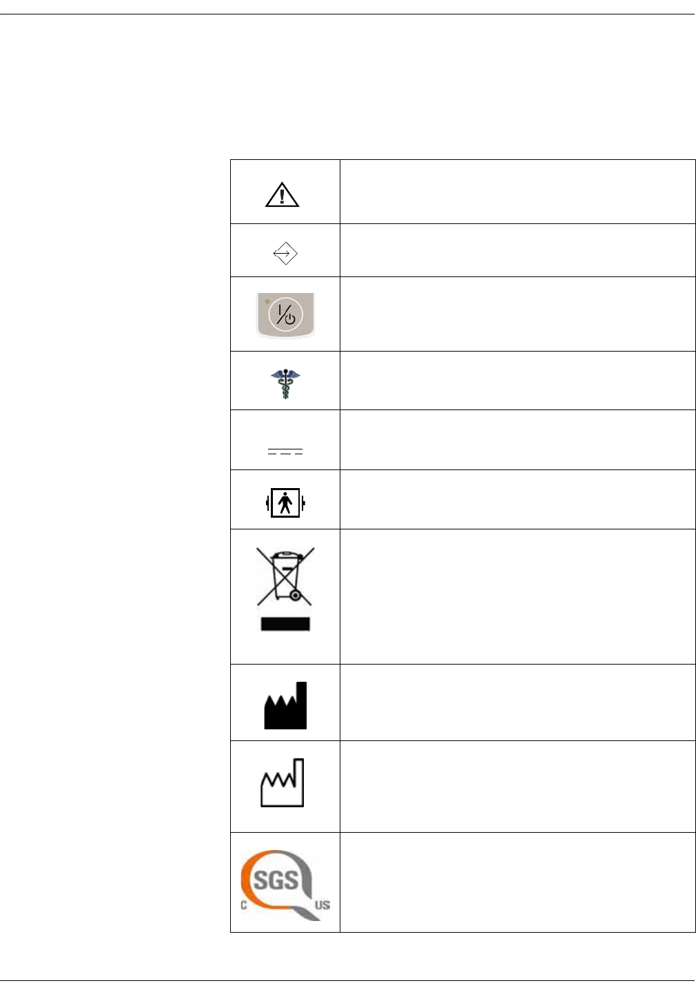
Attention, consult accompanying documents.
External communications port connector
On/Off button (the only mechanical button on the monitor)
Caregiver symbol
External DC power input
Defibrillator-proof type BF equipment
WASTE OF ELECTRICAL AND ELECTRONIC EQUIPMENT
(WEEE): This symbol indicates that the waste of electrical
and electronic equipment must not be disposed as
unsorted municipal waste and must be collected
separately. Please contact an authorized representative of
the manufacturer for information concerning the
decommissioning of your equipment.
Manufacturer: This symbol is accompanied by the name
and the address of the manufacturer.
Manufacturing date: This symbol is accompanied by the
date of manufacture.
Classified with respect to electric shock, fire, and
mechanical and other specified hazards only in
accordance with CAN/CSA C22.2 No. 601.1 and UL 2601-1
(UL 60601-1). Also evaluated to IEC 60601-2-30.
2013-11
1-14 VC150 Vital Signs Monitor KO00065K
Introduction: Monitor symbols
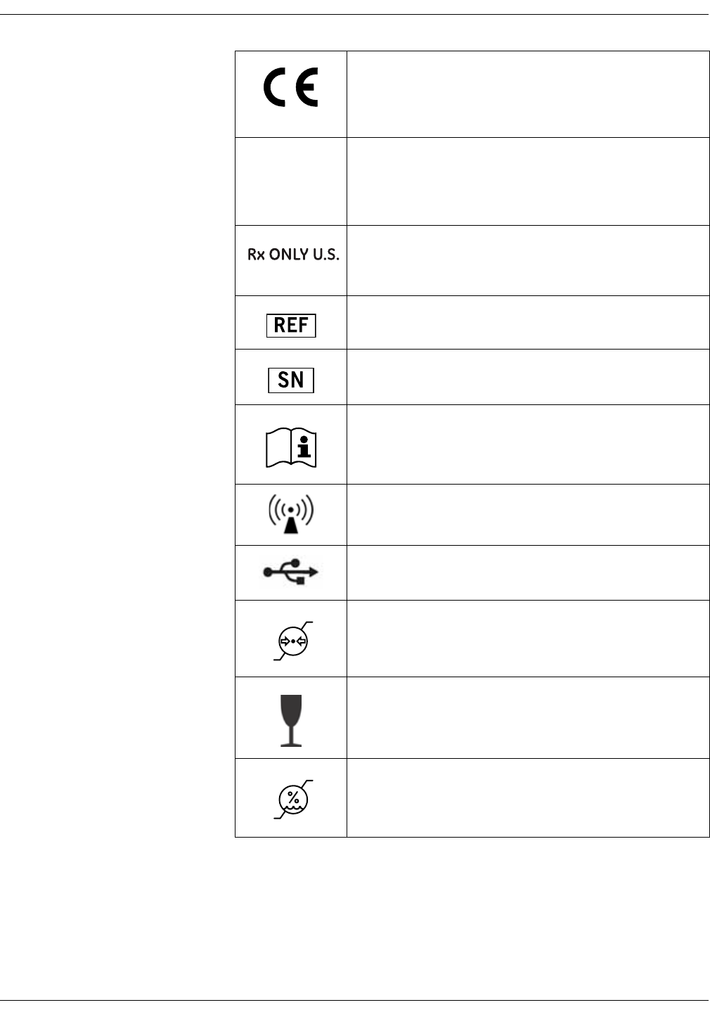
This product conforms with the essential requirements of
the Medical Device Directive 93/42/EEC. Accessories
without the CE mark are not guaranteed to meet the
Essential Requirements of the Medical Device Directive.
IPX1 This product is protected against vertically falling drops of
water and conforms with the IEC 60529 Standard at the
level of IPX1. No harmful effects will come of vertically
falling drops of water making contact with the monitor.
FDA Prescriptive Device symbol for: “Caution: Federal law
restricts this device to sale by or on the order of a
physician.”
Catalog or orderable part number.
Device serial number.
Consult instructions for use.
The unit has a WLAN device inside.
USB port.
Atmospheric pressure limitations.
Fragile. Handle with care.
Humidity limitations.
0598
KO00065K VC150 Vital Signs Monitor 1-15
Introduction: Monitor symbols
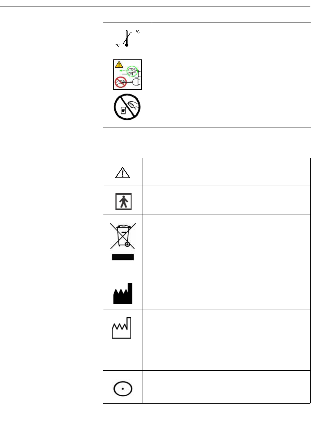
Symbols for Exergen temporal scanner
Temperature limitations.
CAUTION — Safety ground precaution. Remove power cord
from the mains source by grasping the plug. Do not pull on
the cable.
Attention, consult accompanying documents.
Type BF Applied Part.
WASTE OF ELECTRICAL AND ELECTRONIC EQUIPMENT (WEEE):
This symbol indicates that the waste of electrical and
electronic equipment must not be disposed as unsorted
municipal waste and must be collected separately. Please
contact an authorized representative of the manufacturer for
information concerning the decommissioning of your
equipment.
Manufacturer: This symbol is accompanied by the name and
the address of the manufacturer.
Manufacturing date: This symbol is accompanied by the date
of manufacture.
IPX0 Ordinary Equipment.
Measurement On button.
2013-11

1-16 VC150 Vital Signs Monitor KO00065K
Introduction: About this manual
About this manual
Printed copies of this manual
The letter shown in this revision history table relates to the release level of this
document.
Printed copy of the manual
A paper copy of this manual will be provided upon request (in the U.S.). Contact
distributor of this product and request the English manual.
Conventions used in this manual
Within this manual, abbreviations, special styles and formats are used to refer to
concepts, or distinguish among terms viewed on screen, an area you must
select, or a list of menu commands you must select. Examples:
• For technical documentation purposes, the abbreviation GE is used for the
legal entity name, GE Medical Systems Information Technologies, Inc. or GE
Healthcare.
• Service or service personnel refers to service personnel trained by Innokas
Medical or a service provider trained and authorized by Innokas Medical.
• In this manual, the VC150 vital signs monitor is referred to as the monitor.
• Names of physical or hardware keys on the equipment are written in bold
typeface: Reset switch.
• Menu items are written in bold italic typeface: Monitor Setup.
• Emphasized text is in italic typeface.
• Menu options or control settings selected consecutively are separated by
the > symbol: Monitor Setup > NIBP.
• When referring to different sections in this manual, section names are
enclosed in double quotes: “Cleaning and care.”
• The word “select” means choosing and confirming.
• Messages (alarm messages, informative messages) displayed on the screen
are written inside single quotes: 'Learning.'
• Note statements provide application tips or other useful information.
• Any illustrations appearing in this manual are provided as examples only.
They may not necessarily reflect your monitoring setup or data displayed on
your monitor.
• Any names appearing in examples and illustrations are fictitious. The use of
any real person’s name is purely coincidental.
Revision Comments
KO00065K Release level of this document.

KO00065K VC150 Vital Signs Monitor 1-17
Introduction: About this manual
Service requirements
If your product requires warranty, extended warranty or non-warranty repair
service, contact Innokas Medical Technical Support or your local Innokas
Medical representative. To facilitate prompt service in cases where the product
has external chassis or case damage, please advise the representative when
you call.
The representative will record all necessary information and will provide a
Return Authorization Number. Prior to returning any product for repair, a Return
Authorization Number must be obtained.
Follow the service requirements listed below.
• Refer equipment service work only to service personnel trained and
authorized by Innokas Medical.
• Any unauthorized attempt to repair equipment under warranty voids that
warranty.
• It is the user’s responsibility to report the need for service to local Innokas
Medical service or service provider authorized by Innokas Medical.
• Failure on the part of the responsible individual, hospital or institution using
this equipment to implement a satisfactory maintenance schedule may
cause undue equipment failure and possible health hazards.
• Regular maintenance, irrespective of usage, is essential to ensure that the
equipment will always be functional when required.

1-18 VC150 Vital Signs Monitor KO00065K
Introduction: About this manual
This page is intentionally left blank.

KO00065K VC150 Vital Signs Monitor 2-1
2Product overview
2-2 VC150 Vital Signs Monitor KO00065K
Product overview: Front view
Front view
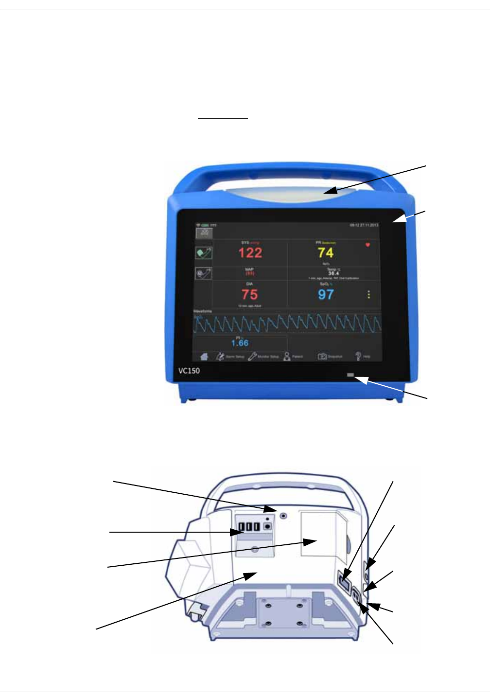
The VC150 monitor display is a touch screen where screen items are selected by
pressing the touch panel with a fingertip.
CAUTION
Do not scratch the screen or press the screen with a sharp object. Do
not use excessive force on the screen.
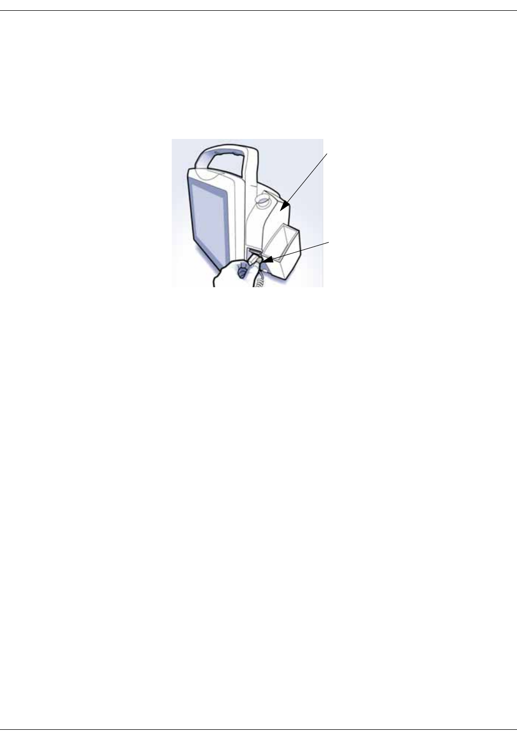
Rear view and left side
Alarm light
Touch screen
Day/night
light sensor
USB-A and power
connectors
Remote alarm connector
USB-B port for
connecting to a PC
Slot for future
expansion
Printer door with patent
label
Power switch and
battery indicators
NIBP hose
connection
SpO2 connection, if
equipped
Product identification
label
KO00065K VC150 Vital Signs Monitor 2-3
Product overview: Right side
Right side
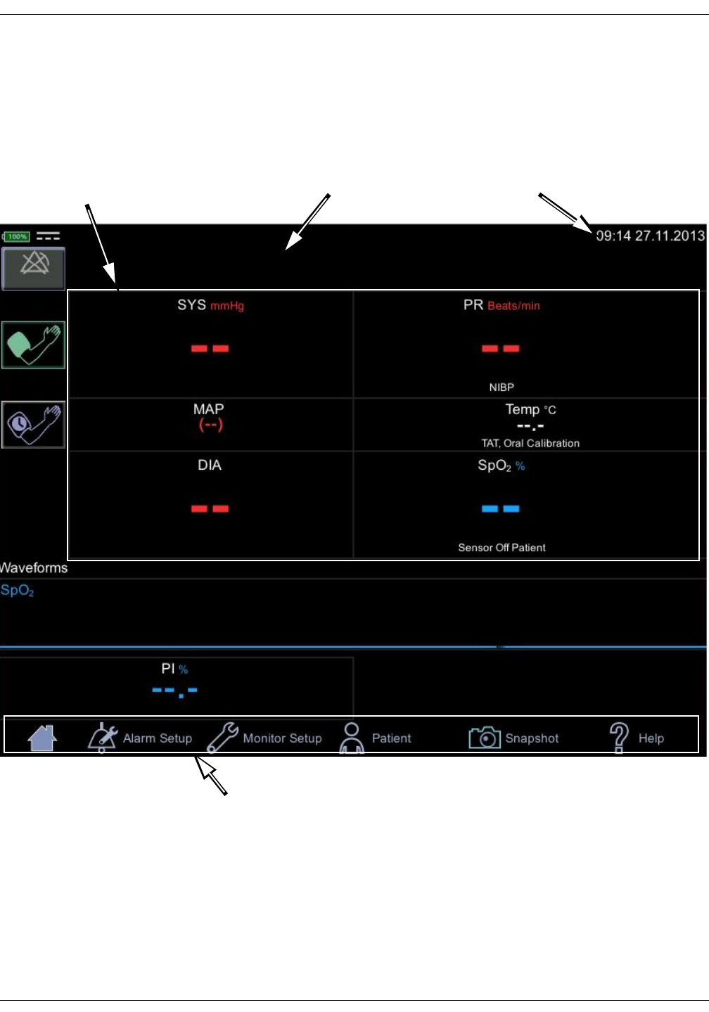
A monitor with the Exergen temperature technology configuration setting
cannot perform Welch Allyn temperature measurements and vice versa. If the
monitor has a Welch Allyn frame installed on the right side of the monitor, then
the monitor uses Welch Allyn temperature technology.
If the monitor does not have the Welch Allyn frame installed, then there are two
alternatives.
1. Exergen technology has been ordered and the monitor is configured for use
of Exergen.
or
2. No temperature measurement has been ordered for the monitor.
WA TEMP label next to WA
probe cord
Welch Allyn (WA) temperature
device, if equipped
2-4 VC150 Vital Signs Monitor KO00065K
Product overview: User interface and connections
User interface and connections
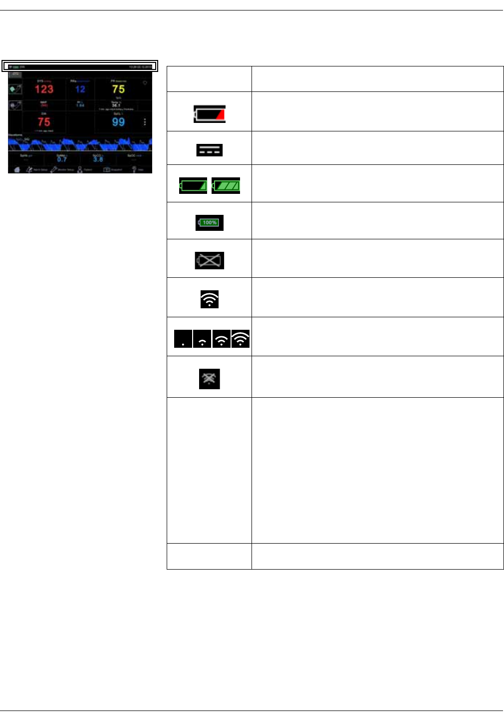
The VC150 screen design is divided into different sections that are covered more
in detail in the tables below.
TIME/DATEPARAMETERS
MAIN MENU
NOTIFICATIONS
KO00065K VC150 Vital Signs Monitor 2-5
Product overview: User interface and connections
Technical information and clinical information
Icon/Text Information displayed
Battery low (color: red).
DC connected.
Battery charging (color: green).
Battery charge level.
Battery failure.
WLAN is active.
Connecting to WLAN.
No WLAN available.
Name Patient name
Service can select following format for the patient name:
• Show both last and first name, or either one if
available.
• Show only last name.
• Show only first name.
• Show only identification.
• Show last name and initial for the first name.
Time and Date Time and Date
2-6 VC150 Vital Signs Monitor KO00065K
Product overview: User interface and connections
Notification area
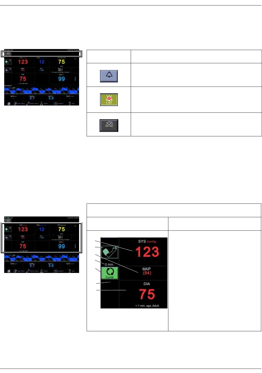
Alarm and technical messages are displayed in the notification area. The alarm
and indicators are active only in monitoring mode.
Parameters
Menu selections for SpO2 settings are different depending upon the purchased
SpO2 technology, additional licenses and selections in the Monitor Setup > SpO2
screen. The screen automatically adjusts to ambient light conditions by toggling
between day and night brightness settings. Default expiration time for
measurement data on screen is 15 minutes. This can be adjusted in the
configuration mode.
Icon/Text Information displayed
Audio alarms are enabled. Action icon for silencing
alarms.
Indication that alarms are silenced. A countdown timer
underneath the indicator displays the remaining time for
the silence.
Indication that alarms are disabled in spot-check mode.
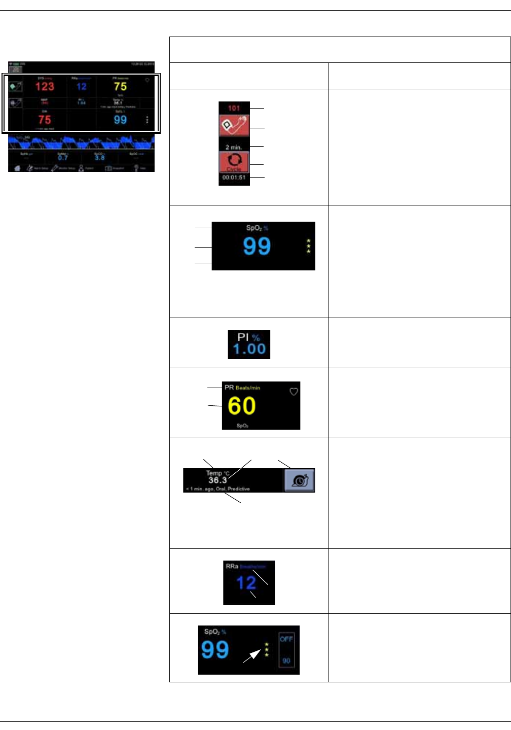
Parameters
Icon/Text Information displayed
1. Systolic blood pressure and unit of
measurement.
2. Inflate icon to start a single
measurement or additional
measurement between automated
measurements.
3. Mean arterial blood pressure (MAP).
4. Selected cycle/interval.
5. Cycle icon to select and start
automated STAT, Cycle or Profile
measurements after the selection.
6. Time to next automated
measurement.
7. Diastolic blood pressure, time of last
measurement and patient type.
1
2
5
6
7
3
4
KO00065K VC150 Vital Signs Monitor 2-7
Product overview: User interface and connections
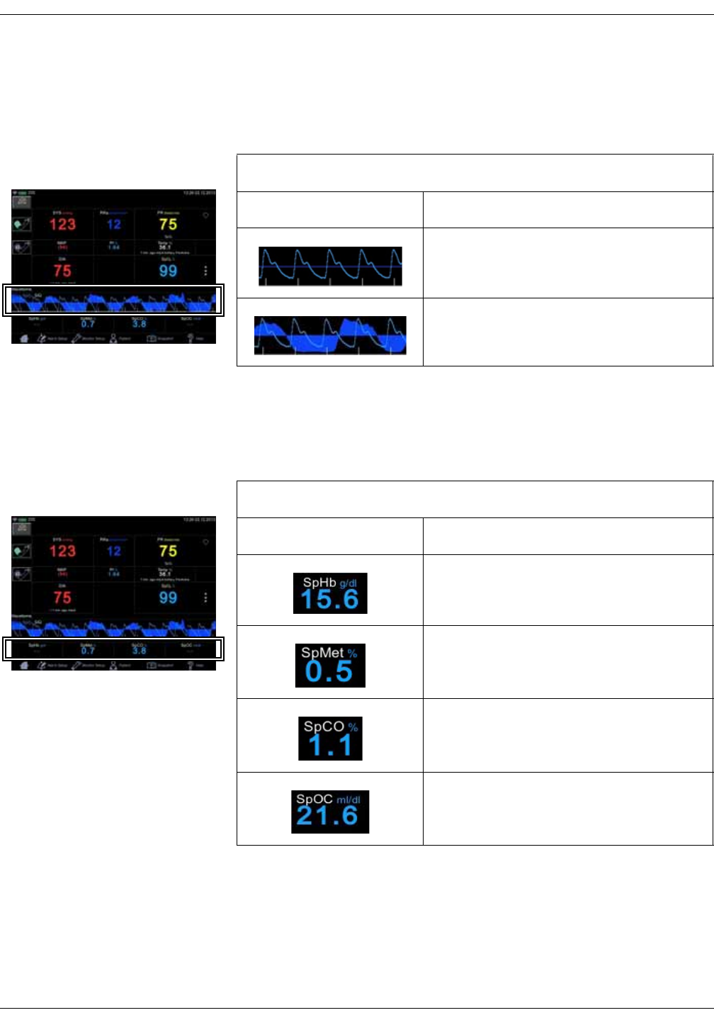
Screen during an NIBP measurement:
1. Cuff pressure in mmHg.
2. Icon to cancel series of automated
measurements.
3. Selected cycle/interval.
4. Animation for cuff inflation.
5. Time to next automated
measurement.
1. Measured parameter and unit of
measurement (SpO2 and % as
example here).
2. Measured value or dashes "--" if no
value is available.
3. Measurement site (if applicable) and
technical error message (if error
condition active).
Perfusion index indicated by a numeric
value.
1. Parameter: Pulse Rate (beats per
minute).
2. The actual pulse rate.
1. Body temperature (optional).
2. The actual measured value.
3. Snail icon to select monitor mode
(Welch Allyn thermometry). Turns to
an animated indicator when
monitoring mode is active.
4. Time since last measurement and
measurement site.
1. Respiration Rate (optional).
2. The actual measured value.
Signal quality indicated by asterisks
Source: Perfusion Index (TruSignal and
Nellcor) and SIQ (Masimo)
Parameters
Icon/Text Information displayed
5
1
2
3
4
1
3
2
1
2
13
4
2
1
2
2-8 VC150 Vital Signs Monitor KO00065K
Product overview: User interface and connections
Graph area
An optional plethysmographic waveform is displayed in the graph area. If the
monitor is equipped with Masimo SpO2 technology, an RRa curve can be
displayed with the waveform.
Masimo data bar (optional)
Optional data from Masimo SpO2 technology is displayed in the Masimo bar at
the bottom of the screen.
Graph area
Icon/Text Information displayed
Plethysmographic waveform (Pleth).
Plethysmographic waveform with Masimo
RRa curve.
Masimo data bar (optional)
Icon/Text Information displayed
Total hemoglobin concentration (optional).
Fractional methemoglobin concentration
(optional).
Fractional carboxyhemoglobin concentration
(optional).
Total arterial oxygen content (optional).
KO00065K VC150 Vital Signs Monitor 2-9
Product overview: Operating modes
Main Menu
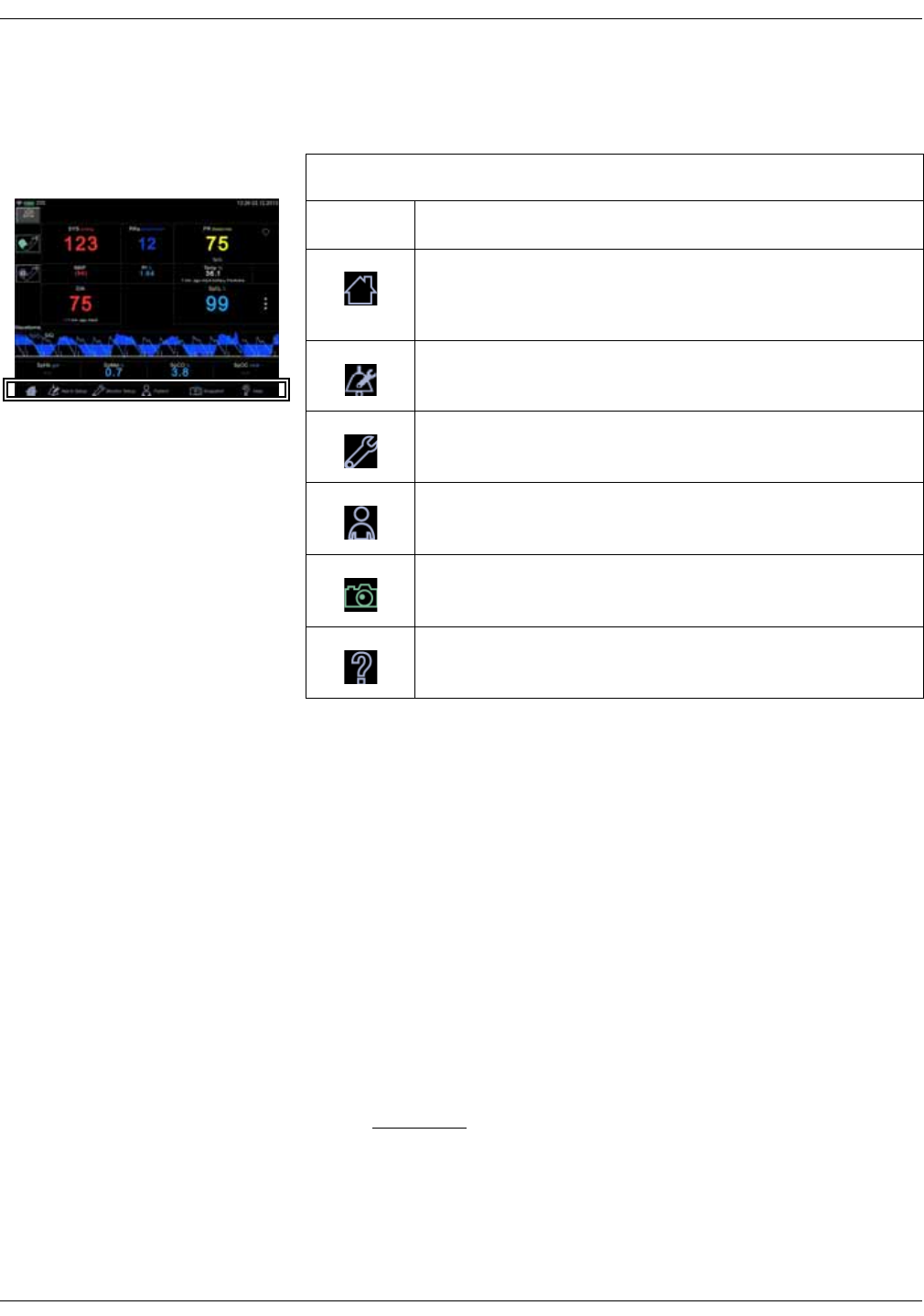
The main menu bar contains icons to navigate within the user interface.
Operating modes
The monitor has following modes of operation:
•Clinical mode
•Spot-check mode
•Monitoring mode
• Configuration mode with three levels of access:
•Monitor Setup for settings by any user.
•Default Setup (password-protected area) for settings by someone at
the hospital or care unit that has the training and authority to set up
default settings for the monitor.
•Service Mode (password-protected area) for additional configuration,
calibration and maintenance of the monitor.
CAUTION
Service Mode is intended for use by qualified and trained service
personnel only.
Main menu
Icon/Text Information displayed
The home icon is used to close the active monitor setup menu
screen and revert the monitor to the main screen where the
patient’s measurements are displayed.
Alarm Setup is used to adjust for various alarm settings and
select between spot-check and monitoring modes.
Monitor Setup is used to access a screen where you can
configure and adjust monitor operation.
Patient is used to access stored measurements, and manage
patient and caregiver identity.
Snapshot is used to store parameter measurement data into
local patient history.
Help is used to access an index screen of topics and a context
sensitive help.

2-10 VC150 Vital Signs Monitor KO00065K
Product overview: Operating modes
Clinical mode
The clinical mode starts right after the
monitor is turned on. When the home
screen appears and two beeps are
heard, a patient’s vital signs can be
monitored.
The clinical mode will end when the
monitor is put into standby, the monitor
is shut down, or Service Mode is entered.
During Monitor Setup and Default
Setup, monitoring processes continue in
the background. The clinical mode
resumes after selecting the home icon.
In the clinical mode, all parameters are available for monitoring and user
settings can be adjusted. Alarm limits are available only in monitoring mode, not
in spot-check mode.
Spot-check mode and monitoring mode
Clinical spot-check mode (sometimes called manual mode) is intended for brief
examinations, while clinical monitoring mode is intended for longer
examinations. In spot-check mode, alarms are not active. In monitoring mode,
alarms are active. The mode is selected in the Alarm Setup screen.
Monitor configuration
The monitor has three types of settings:
1. The current settings, which can be adjusted by the regular user. This is reset
each time a patient is changed.
2. The current default settings, to which the monitor returns upon starting a
new patient. These defaults can be changed only in the configuration mode.
3. Factory defaults for alarm settings on the monitor when it is first received by
the customer. Service can revert alarm settings to factory defaults if
necessary.
All users can access Alarm Setup, Monitor Setup and Patient to configure or
customize user-preferred default settings for measurements in clinical mode.
When a menu icon is selected, the related menu screen will be displayed, the
menu item will be highlighted and other menu items dimmed. That indicates you
are in that section.
Clinical mode screen
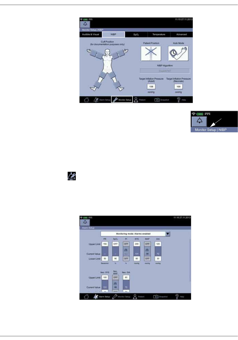
KO00065K VC150 Vital Signs Monitor 2-11
Product overview: Operating modes
Current settings or default settings can be adjusted
while a patient is being monitored, but new
examinations cannot be initiated while in the
configuration mode and the parameter data will not be
displayed on screen until the user returns to clinical
mode. The name of the menu screen is displayed on the upper left section of the
screen.
Alarm setup
The alarm limit adjustment allows you to change upper and lower alarm limit
settings used on individual parameter items while monitoring a patient. If a
parameter alarm limit has been set OFF in the configuration mode, color of the
alarm limit on the Alarm Setup screen is displayed as gray and cannot be
adjusted. Also, you can select spot-check or monitoring mode here. Refer to
“Alarm limit setup” on page 3-14 for instructions. Depending on the purchased
licenses for options, the screen items will vary.
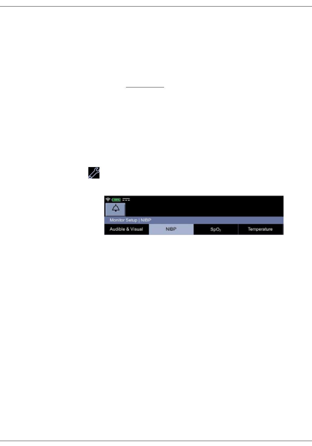
2-12 VC150 Vital Signs Monitor KO00065K
Product overview: Operating modes
NOTES
• There are no alarm limits and no clinical alarm messages for temperature
measurement.
• All changes are temporary and return to the default configuration settings
when the monitor is turned off or a new patient is admitted. To permanently
change the alarm settings refer to “Configuration mode settings” on page 3-
12.
WARNINGS
Monitors located in the same clinical area may contain different alarm
default settings, which can result in a potential hazard.
Always check your alarm settings before using the monitor.
Caution should be taken to not set alarm limits to extreme values, as
this can render the alarm system useless.
Monitor Setup
Monitor Setup consists of four tabs that all users are allowed to configure. These
configurations are only for the current patient. To make these changes
permanent, these must be changed in the configuration mode.
Audible & Visual is used to configure alarm and display brightness and
sound settings. Refer to “Audible & Visual” on page 3-19 for more
information.
NIBP is used to select cuff position, target inflation pressures and patient
position. Refer to “NIBP” on page 6-1 for more information.
SpO2 is used to select measurement site and visual elements of the SpO2
parameter in clinical mode. Refer to “GE TruSignal SpO2” on page 7-1,
“Masimo SpO2” on page 8-1 and “Nellcor SpO2” on page 9-1for more
information.
Temperature is used to configure temperature measurement. Refer to
“Temperature setup” on page 3-25 for more information.
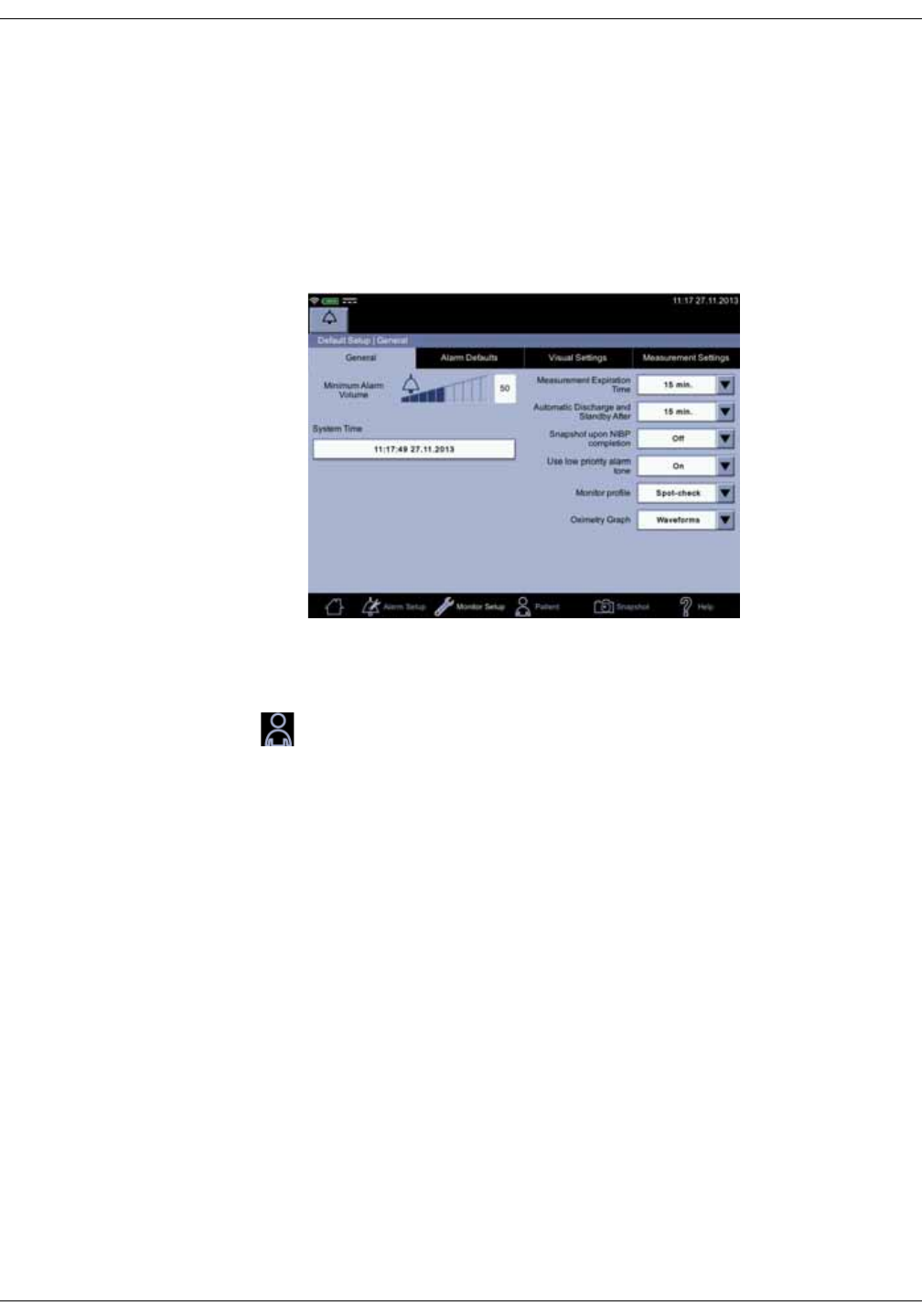
KO00065K VC150 Vital Signs Monitor 2-13
Product overview: Operating modes
Default Setup
Password-protected Default Setup is used for a more advanced configuration
for General, Alarm Defaults, Visual Settings and Measurement settings. It is
intended for someone at the hospital or care unit that has the training and
authority to configure default settings for the monitor. Refer to “Default setup”
on page 14-1 for configuration instructions. Availability of configurable features
depends on what parameter-related options have been ordered. Changes
applied in Default Setup remain set even if the monitor is switched off.
Patient
Patient- and caregiver-related data in Patient can be accessed for the following:
• Entering patient information and searching for patients
• Logging the caregiver on and off
• Viewing, editing and sending snapshots
NOTE
Refer to “Patient and caregiver data” on page 5-1 for more information.
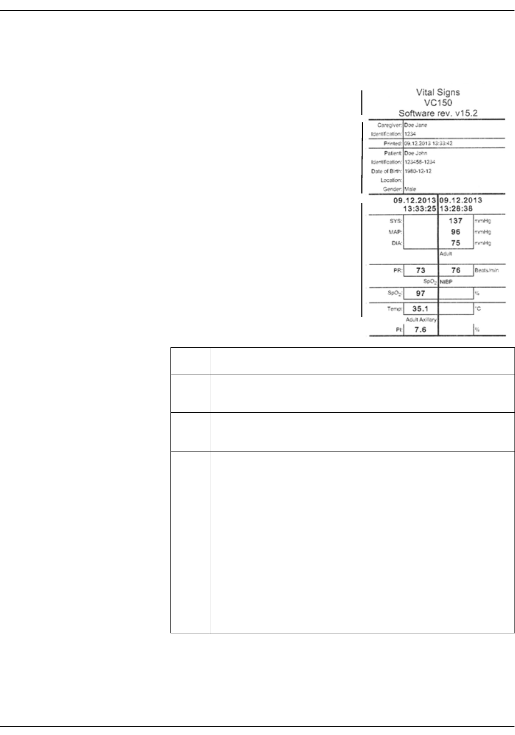
2-14 VC150 Vital Signs Monitor KO00065K
Product overview: Printout
Printout
The printer is an optional feature of the
monitor. If your monitor contains a
printer, each time a printout is started
the following information is printed.
Contents of the printout can be
selected in the Patient screen.
Item Name
1 Monitor name and model number. Current software revision. The
software revision letters map to a numeric software revision.
2 Patient name. Time of printing. Information about the patient and
care facility.
3 Snapshot
• Left side: printer line headings.
• Middle: Vital signs information is displayed as a snapshot (or
collection) of all available data at the time. Two different
shapshots can be printed side by side with the monitor strip
printer. Non-continuous values such as NIBP, predictive
temperature and Exergen temperature are automatically
captured when the measurement is completed. Continuous
values (SpO2 and temperature in the monitor mode) are stored
with the Snapshot icon. Printed contents vary depending on
which SpO2 or temperature technology is used to provide the
data.
• Right side: Units of measurement.
1
3
2

KO00065K VC150 Vital Signs Monitor 2-15
Product overview: Remote Management
Remote Management
Some service work can be done through remote service interface.
WARNING
Do not use the monitor for clinical measurements during remote service
session.
The following applies to the remote service:
•Start Remote Service icon is selected in Monitor Setup > Advanced.
• A remote service active screen displays the IP address of the monitor,
Waiting for Service User actions and Cancel. If service is logged on, the
monitor displays Remote User active, please do not turn the monitor off!
and no Cancel on the screen.
• Remote service is stopped after 5 minutes of inactivity.
• If completion of service work requires restarting the monitor, the remote
service is not restarted automatically.
Battery low shutdown or system failure
If battery power is nearly depleted or the system detects a serious failure, the
monitor will not allow new examinations and will shut down. Refer to “Alarms”
on page 4-1 for details and alarm messages.
Sounds
The monitor generates sounds to indicate parameter events, and physiological
or technical alarms.
Battery charger sounds
Whenever the external DC charger is connected and disconnected, the monitor
sounds a short tone.
2-16 VC150 Vital Signs Monitor KO00065K
Product overview: Essential performance
Essential performance
The VC150 vital signs monitor measures physiological parameters within
specified accuracy limits, raises alarms based on user-defined conditions, or
generates either a technical alarm or an indication of abnormal operation.
The measurement ranges and accuracies depend on the measurement
technology and are summarized in the table below.
GE TruSignal SpO2 accuracy and ranges
Measurement range
SpO2 saturation range 0 to 100%
Pulse rate range 30 to 300 bpm
Measurement accuracy
SpO2 saturation accuracy 70% to 100% ±2 to ±3 digits
Pulse rate accuracy 30 to 250 bpm ±2 bpm to ±5 bpm
(rms)
Nellcor™ Sensor accuracy and ranges
Measurement range
SpO2 saturation range 1% to 100%
Pulse rate range 20 to 250 bpm
Respiration rate range 4 to 40 breaths/minute
Measurement accuracy
SpO2 saturation accuracy 70% to 100% ±2 to ±3.5 digits
Pulse rate accuracy 20 to 250 bpm ±3 bpm (rms)
KO00065K VC150 Vital Signs Monitor 2-17
Product overview: Essential performance
Masimo rainbow SET® sensor accuracy and ranges
Measurement range
SpO2 saturation range 0 to 100%
Pulse rate range 25 to 240 bpm
SpCO range 0 to 99%
SpMet range 0 to 99.9%
SpHb range 0 to 25 g/dl
Respiratory Rate range 0 to 70 breaths per minute
Measurement accuracy
SpO2 saturation accuracy 70% to 100% ±2% to ±3%
Pulse rate accuracy 25 to 240 bpm ±3 to ±5 bpm (rms)
Respiration rate accuracy 4 - 70 ± 1 breath per minute
SpCO accuracy 1 - 40 ± 3%
SpMet accuracy 1 - 15 ± 1%
SpHb accuracy 8 - 17 ± 1 g/dl (arterial or venous)
2-18 VC150 Vital Signs Monitor KO00065K
Product overview: Essential performance
NIBP accuracy and ranges
Measurement range (Auscultatory algorithm)
Systolic BP range 30 to 245 mmHg (adult/ped)
MAP range 15 to 215 mmHg (adult/ped)
Diastolic BP range 10 to 195 mmHg (adult/ped)
Pulse rate range 30 to 200 beats/min (adult/ped)
Measurement accuracy (Auscultatory algorithm)
Blood pressure accuracy mean error ≤ 5 mmHg,
standard deviation ≤ 8 mmHg
Pulse rate accuracy ± 3.5% or 3 bpm, whichever is higher
Measurement range (SuperSTAT algorithm)
Systolic BP range 30 to 290 mmHg (adult/ped)
30 to 140 mmHg (neonate)
MAP range 20 to 260 mmHg (adult/ped)
20 to 125 mmHg (neonate)
Diastolic BP range 10 to 220 mmHg (adult/ped)
10 to 110 mmHg (neonate)
Pulse rate range 30 to 240 beats/min (adult/ped)
30 to 240 beats/min (neonate)
Measurement accuracy (SuperSTAT algorithm)
Blood pressure accuracy mean error ≤ 5 mmHg,
standard deviation ≤ 8 mmHg
Pulse rate accuracy ± 3.5% or 3 bpm, whichever is higher
KO00065K VC150 Vital Signs Monitor 2-19
Product overview: Product specifications
Product specifications
Welch Allyn temperature accuracy and ranges
Measurement range
Patient temperature range 26.7° C to 43.3° C (80.0° F to 110.0° F)
Measurement accuracy
Monitor mode temperature accuracy ±0.1° C; ±0.2° F
Exergen temperature accuracy and ranges
Measurement range
Temperature range 16° C to 43° C (61° F to 110° F)
Measurement accuracy
Temperature accuracy ±0.1° C (±0.2° F)
Mechanical
Dimensions
Height 24.7 cm (9.75 in)
Width 24.2 cm (9.5 in) without Welch Allyn temperature
29.2 cm (11.5 in) with Welch Allyn temperature
Depth 13.6 cm (5.3 in)
Weight (including battery) 2.8 kg (6.2 lb)
Mountings Tabletop (self-supporting on rubber feet), mounted on a roll stand or a
wall mount bracket
Portability Carried by handle
Power requirements
Universal power converter PN: MO000145

2-20 VC150 Vital Signs Monitor KO00065K
Product overview: Product specifications
Protection against electrical shock Class I
AC input 100 - 240~1.1A
DC output voltage 24 VDC at 2A
The AC mains power adapter contains a non-resettable and non-
replaceable fuse.
Rated supply frequency 50 - 60 hZ
Monitor
Screen Resistive touch screen
Protection against electrical shock Internally powered or Class I when powered from specified external
medical power supply.
DC input voltage 24 VDC, supplied from a source conforming to IEC 60601-1.
Fuses The monitor contains two T3.5A replaceable fuses on the mother board
(F3) and USB board (F1). The battery packet contains overcurrent and
temperature protection. The fuses protect the low voltage DC input and
the main battery.
Main battery Refer to “Monitor battery specifications” on page 13-6.
Environmental
Operating temperature Without temperature sensors: 5 to 40° C (41 to 104° F)
With Welch Allyn temperature sensor: 10 to 40° C (50 to 104° F)
With Exergen temperature sensor: 16 to 40° C (61 to 104° F)
Humidity range 5% to 95% non-condensing
Operating atmospheric pressure 700 hPa to 1060 hPa
Storage/transport
Storage temperature – 20° C to + 50° C (– 4° F to + 122° F)
Atmospheric pressure 500 hPa to 1060 hPa
Humidity range 5% to 95% non-condensing

KO00065K VC150 Vital Signs Monitor 2-21
Product overview: Printer specifications
Printer specifications
Connectivity specifications
Printer type Thermal dot array
Resolution 384 dpi horizontal
Paper type The paper roll used by the printer must be compatible with 32018145.
Languages printed All user interface languages.
Wireless specifications
WLAN connection standard 802.11 standard (a/b/g/n)
WLAN speed Maximum:
a 54 Mb/s
b 11 Mb/s
g 54 Mb/s
n 150 Mb/s
WLAN output level (Effective Radiated
Power, ERP)
2.4 GHz 10 dBm
5 GHz 13 dBm
WLAN bands Capable of communicating on 2.4 GHz and 5.1 GHz bands.
The allowable range of DSCP values per
Access Category for interoperability
between WMM-compliant clients
Non-realtime clinical data: 0 7
Non-realtime, non-clinical data: 8 23
Use of general-purpose WLAN network No dedicated wireless network required.
WLAN encryption methods None
WEP
WPA-PSK
WPA-EAP
WPA Custom
Authentication WEP: Open System, Shared Key
WPA-PSK: WPA-TKIP, WPA2-AES
WPA-EAP: TLS, TTLS, PEAP, FAST
WPA Custom: free configuration within limits of linux/wpasupplicat
support
Number of SSID profiles Up to 4 SSID profiles that service can define and configure.

2-22 VC150 Vital Signs Monitor KO00065K
Product overview: Connectivity specifications
WLAN frequency band settings 2.4 GHz band
5.1 GHz band
2.4 & 5.1 GHz bands
Modulation OFDM (802.11a/g/n), DSSS/CCK (802.11b)
WLAN information displayed Transmit power (dBm)
SSID
RTS Threshold
Fragmentation Threshold
IP Address
Bit Rate
Link Quality
Noise Level
Signal to Noise Ratio
Signal level (RSSI) in terms of dBm
Network adapter MAC address
Other WLAN info
EMC Compliance Complies with IEC Publication 60601-1-2 Medical Electrical Equipment,
Electromagnetic Compatibility Requirements and Tests and CISPR 11
(Group 1, Class B) for radiated and conducted emissions.
Access point information displayed Access point radio frequency
Access point radio MAC address (BSSID)
RF information displayed Radio frequency (i.e., the frequency associated with the channel number)
Transmit power in terms of dBm
Signal level (RSSI) in terms of dBm
Radio diagnostic information displayed
(counters can be reset)
Packets received
Packets transmitted
Bytes received
Bytes transmitted
Receiving errors
Transmission errors
Wireless specifications

KO00065K VC150 Vital Signs Monitor 2-23
Product overview: Open source software notice
Open source software notice
This product includes certain Open Source software.
The exact terms of the licenses, disclaimers, acknowledgements, and notices are
reproduced in the materials provided with this product. Innokas offers to provide
you with the source code as defined in the applicable license.
Send email to: sourcecode.request@innokasmedical.fi
or a written request to:
Source Code Requests
Innokas Yhtymä Oy
Vihikari 10
FI-90440 Kempele
Finland
This offer is valid for a period of three (3) years from the date of the distribution of
this product by Innokas.
By submitting a request, you give your consent that Innokas (or third parties on
behalf and under direct authority of Innokas) will process your personal data.
The processing will be done for the purpose of the request and the undertakings
related to it. The main reason for storing this data is to prove compliance with
the license terms. The data processing will be done in compliance with Innokas
guidelines and applicable legislation.

2-24 VC150 Vital Signs Monitor KO00065K
Product overview: Open source software notice
This page is intentionally left blank.

KO00065K VC150 Vital Signs Monitor 3-1
3Getting started

3-2 VC150 Vital Signs Monitor KO00065K
Getting started: Introduction
Introduction
This chapter provides an overview of monitor operation and accessories. Before
attempting to use the monitor, take a few minutes to become acquainted with
the monitor and its accessories. Unpack the accessory items carefully. This is
also a good time to check for any damage or accessory shortage. If there is a
problem or shortage, contact Innokas Medical.
It is recommended that all the packaging be retained in case the monitor must
be returned for service in the future.
NOTE
The monitor cannot be used before the battery is installed. Only service
personnel may remove and install the battery.
Setting up NIBP connections
1. Connect the end of the air hose that
has quick-release clips to the NIBP
connector on the left side of the
monitor (the touch screen being the
front part). Make sure that the hose is
not kinked or compressed.
NOTE
To disconnect the hose from the
monitor, squeeze the quick-
release clips together and pull the
plug from the NIBP connector.
2. Select the appropriate cuff size.
Measure patient’s limb and select an appropriately sized cuff according to
size marked on the cuff or cuff packaging. When cuff sizes overlap for a
specified circumference, choose the larger size cuff.
WARNING
Selecting a correct hose and cuff is very important. Do not mix neonatal
and adult hoses! An adult hose pressure is extremely dangerous for
neonates. The air hoses are color-coded according to patient
population. The gray 12- or 24-foot hose (3.66 m or 7.3 m) is required on
patients who require cuff sizes from infant through thigh cuffs. The light
blue 12-foot hose (3.66 m) is required for the neonatal cuff sizes #1
through #5.
Accuracy of NIBP measurement depends on using a cuff of the proper
size. It is essential to measure the circumference of the limb and to
select the proper size cuff. If it becomes necessary to move the cuff to
another limb, make sure the appropriate size cuff is used.

KO00065K VC150 Vital Signs Monitor 3-3
Getting started: Setting up NIBP connections
CAUTION
The RADIAL-CUF has been validated for use only with GE SuperSTAT
algorithm for adult obese patients. The RADIAL-CUF has not been
validated for use against the GE Auscultatory algorithm. Refer to the
RADIAL-CUF instructions for use for sensor requirements.
3. Inspect cuff/adapter/air hose for damage. Replace cuff when aging, tearing,
leaks or weak closure is apparent. Do not inflate cuff when unwrapped.
CAUTIONS
Incorrect cleaning procedures will contaminate the accessory or
shorten lifetime of the cuffs or hoses. Clean according to the specific
cleaning and disinfection instructions provided with the accessory.
Do not use cuff if structural integrity is suspect.
4. Connect the cuff to the air hose. Refer to “NIBP” on page 6-1 of this manual
for complete cuff connection instructions.
CAUTION
Always use the appropriate hose and cuff combination for the patient.
Any attempt to modify the hose may prevent the monitor from
switching between the neonate and adult/pediatric measurement
modes.
NOTE
Ensure the cuff and the hose are securely connected. Make sure no leak
occurs.
5. Refer to “NIBP” on page 6-1 of this manual for complete instructions on
taking an accurate NIBP determination.
NOTES
• Use only GE BP cuffs. The size, shape, and bladder characteristics can
affect the performance of the instrument. The accuracy of the
DINAMAP blood pressure algorithm has only been confirmed when used
with GE cuffs. Refer to the VC150 supplies and accessories document
for order part numbers.
• When the monitor displays Adult in Monitor Setup > NIBP, it
encompasses both adult and pediatric patients.
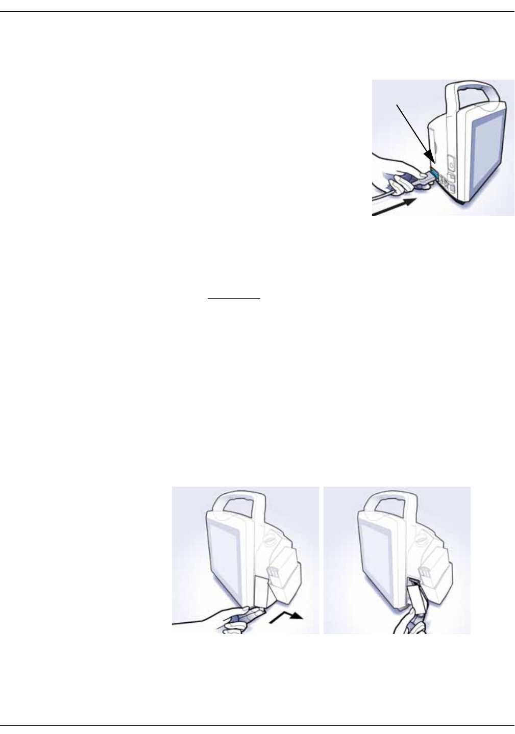
3-4 VC150 Vital Signs Monitor KO00065K
Getting started: Setting up SpO2 connections
Setting up SpO2 connections
1. Check the SpO2 technology used
(Masimo, GE TruSignal or Nellcor) on the
label above the connector. If you cannot
read the label, ask the nurse manager or
service what SpO2 technology is used.
2. Depending on the sensor type, plug a
SpO2 sensor into the SpO2 sensor
extension cable or directly to the
monitor.
3. If needed, plug the SpO2 sensor
extension cable into the SpO2 sensor
connector on the monitor.
Refer to the “SpO2” section of this manual for complete instructions on
monitoring SpO2.
CAUTION
Never use any other technology than what is stated on the label.
Connectors of cables used with other SpO2 technologies may fit the
monitor SpO2 connector, but these must not be used.
Setting up temperature connection
Welch Allyn (optional)
If the monitor is equipped with Welch Allyn temperature, follow instructions
below. The probe connector is located under the cover.
1. Remove the cover.
Technology
label
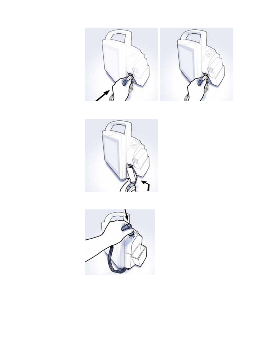
KO00065K VC150 Vital Signs Monitor 3-5
Getting started: Setting up temperature connection
2. Plug in the temperature probe.
3. Replace the cover.
4. Insert the temperature probe into the probe well at the side of the monitor.
NOTE
A probe for oral and axillary measurement has a blue ejection button that
pairs with a blue probe well. A probe for rectal measurement has a red
ejection button that pairs with a red probe well. Although the detection
mechanism at the probe well allows the Welch Allyn device to recognize the
used probe, always ensure that the probe and the probe well colors match.
5. Refer to “Welch Allyn temperature” on page 11-1 of this manual for
complete instructions on taking a temperature reading.
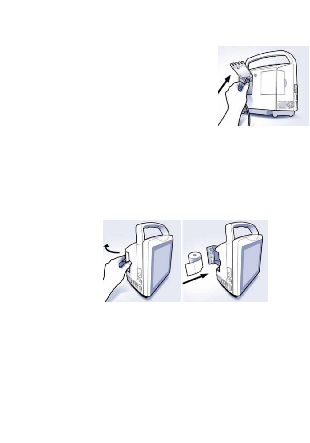
3-6 VC150 Vital Signs Monitor KO00065K
Getting started: Connecting USB accessories
Connecting USB accessories
1. Open the USB hatch at the back of the
monitor.
2. Connect the accessories.
3. Close the hatch and secure the cables
by tightening the knob.
Installation/replacement of printer paper
If the optional printer is available, follow these steps to install or replace the
paper.
1. With the monitor powered off, turn it so that the side with the printer is
facing you.
2. Place your thumb on the indented area of the printer door, then pull it out.
The printer door will pop open.
3. Place the roll of paper into the compartment so that the end of the paper
comes off on the right side of the roll (rotates clockwise). Place the roll of
paper in the holding bracket that is integrated in the door of the printer,
making sure the paper extends out of the printer cavity at least 5 cm (two
inches).
4. Firmly press the door to close it.
USB

KO00065K VC150 Vital Signs Monitor 3-7
Getting started: Electrical connection
Paper storage
Store thermal paper in a cool, dry place. The printed strip (thermal paper
recording) should not be:
• Exposed to direct sunlight
• Exposed to temperatures over 38° C/100° F or relative humidity over 80%
• Placed in contact with adhesives, adhesive tapes, or plasticizers such as
those found in all PVC page protectors
NOTES
When in doubt about long-term storage conditions, store a photocopy of
the thermal paper recording.
The paper is thermally activated; therefore, do not store it in a hot place as
discoloration may result.
Use only replacement paper rolls (pn 32018145 for box of 10) ordered from your
Innokas Medical representative.
Electrical connection
Connect the supplied power cord to the mains power. Use only the original cord
or a cord listed in the VC150 supplies and accessories document for the country
of use.
Power sources
Refer to “Monitor battery specifications” on page 13-6 for details. With external
DC power connected, the green charging indicator will light to indicate that the
battery is charging.
DANGER
ELECTRIC SHOCK — Do not touch the patient and the DC power input
connector pins simultaneously.
WARNING
Examine the power cord periodically. Discontinue use and replace if
damaged. Replace the power cord, as necessary, with a cord listed in
the VC150 supplies and accessories document for the country of use.
NOTE
Be sure to unplug the power supply from the AC outlet before transport.
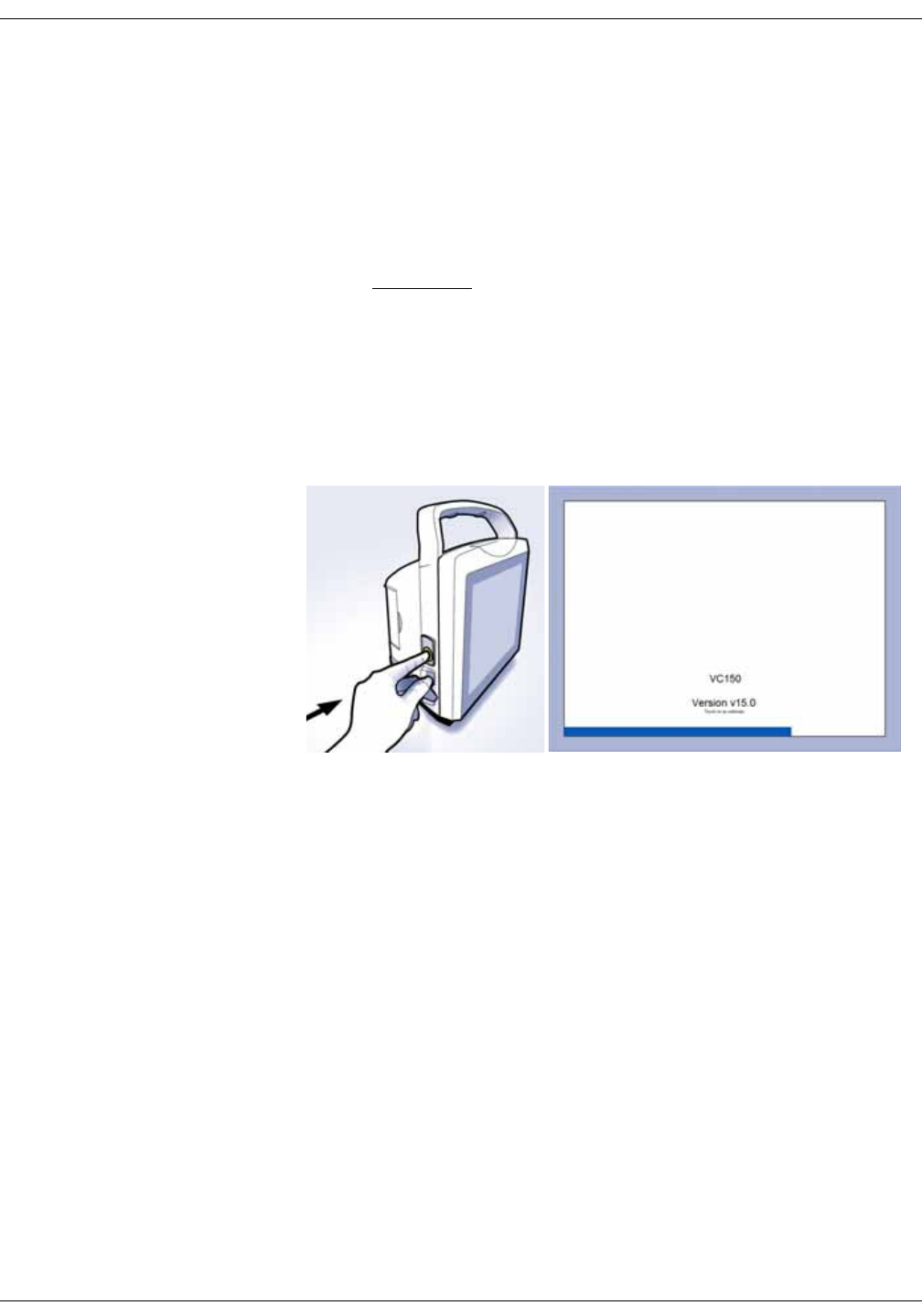
3-8 VC150 Vital Signs Monitor KO00065K
Getting started: Monitor on/off
Monitor on/off
NOTE
For safety reasons, the monitor is designed so that it can be powered
without a battery while its power supply is connected to mains. However,
clinical mode is not possible without a functional internal Lithium battery
specified for VC150.
WARNING
Inspect the device for damage before use.
1. Push the power On/Off button on the left side of the monitor to turn it on.
During power-up, the monitor displays the software version on a white
power-up screen with grayish blue borders. The monitor will also flash the
alarm light at the top. After the monitor has completed the start-up
sequence, there will be two short tones and the opening screen changes to
the home screen.
NOTES
If the monitor fails to sound the start-up tones, or the alarm lights do not
blink in three colors during start-up, do not use the monitor. This indicates
problems with the audible alarm circuit or alarm lights. Potential alarms
cannot be heard or seen. Contact service.
If the power-up screen does not change to the home screen within 2
minutes, contact service.
2. If you notice that selections do not accurately track the position of your
finger, it is possible to recalibrate the touch screen on this device during
power-up. Refer to “Touch screen recalibration” on page 3-9.
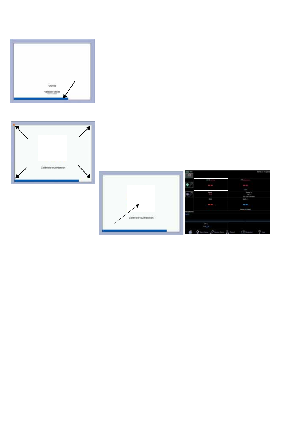
KO00065K VC150 Vital Signs Monitor 3-9
Getting started: Monitor on/off
Touch screen recalibration
1. To recalibrate the screen, turn off the monitor and turn it on again.
2. Wait until a blue progress bar has extended over a half of its total length.
The monitor will display the current software version and the text Touch to
recalibrate. Now press anywhere on the white screen area for three
seconds to begin the recalibration process. You can also press power button
shortly to begin recalibration.
NOTE
If the blue progress bar reaches the end and the black home screen
appears, you have to start the monitor again to recalibrate it.
3. You can start the recalibration when a blinking rectangle appears in the top
left corner (A).
4. Press the rectangle to select it. Hold your finger down for a moment, if
necessary. If the software registered the selection, the rectangle moves to
the next location.
5. Select the rectangle at each location (B, C, D and E).
NOTE
Do not slide your finger on the screen. Selections are made by pressing the
screen with your fingertip and then lifting the finger away from the screen.
6. When the recalibration is complete, the home screen will appear and you
can continue using the monitor.
Verification of the touch screen recalibration
1. Select Help.
2. Close the help screen with Close.
3. Select the systolic NIBP area to jump to the NIBP screen.
4. Select the home icon to exit the NIBP screen.
If you are not able to perform the commands because the calibration is still off,
try again to recalibrate. If even the new calibration does not solve the issue,
contact service.
A
BC
D
E
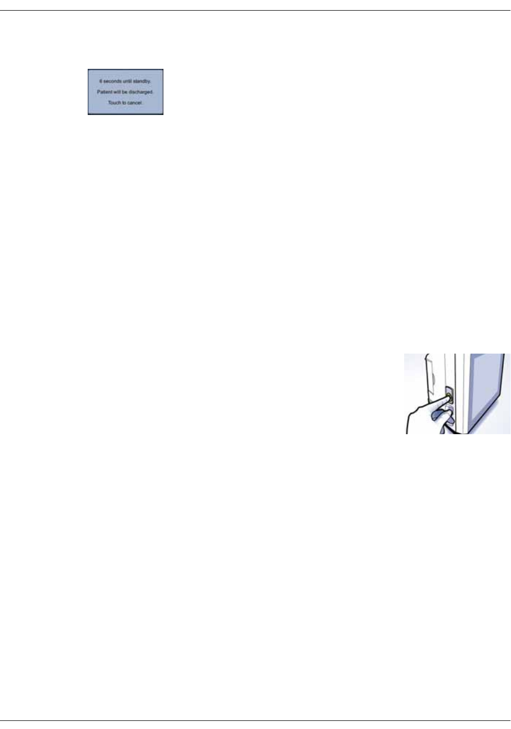
3-10 VC150 Vital Signs Monitor KO00065K
Getting started: Monitor on/off
Standby
The monitor has an automatic standby feature in order to conserve battery life.
If the monitor is in clinical mode and has been inactive for a period of time, the
screen turns black and the monitor switches to standby mode. Within first two
minutes of standby, you can activate the monitor again by touching the screen.
After two minutes of standby, press the On/Off button to activate the screen
again. The inactivity timer can be adjusted in configuration mode. When running
on battery, the monitor is automatically shut down after 15 minutes of standby,
NOTES
Refer to “Clinical mode” on page 2-10 for a description of clinical mode.
The monitor will not automatically switch to standby mode if 1) this is
disabled in configuration mode, or 2) a visible alarm (low, medium, high) is
displayed on screen during monitoring mode.
The monitor switches to standby when:
• The touch panel has not been operated for a configured period of time, and
• There are no ongoing measurements.
Monitor standby
User-initiated standby
Push On/Off button briefly to put the monitor into a
standby state. This is possible if the monitor is in spot-
check mode or there are no ongoing measurements
in monitoring mode.
Unless disabled by service, the monitor will
automatically switch to standby mode if monitor has
been idle for a configured period of time and not
currently used for patient monitoring. If the monitor is disconnected and remains
in standby mode for over 15 minutes, the monitor will shut down.
Resuming operation
Push the On/Off button again or touch the screen to resume the active clinical
mode.
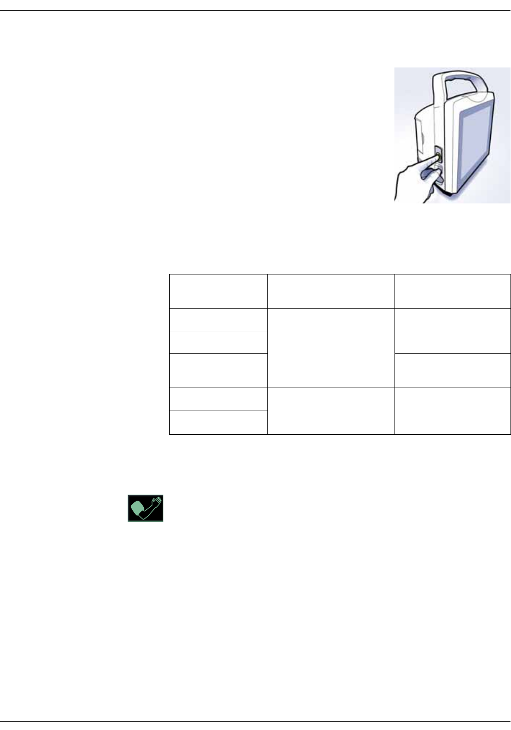
KO00065K VC150 Vital Signs Monitor 3-11
Getting started: Procedure for testing alarms
Turning the monitor off
If determinations are complete and the monitor will
not be used for a longer period of time, push the
On/Off button until the monitor starts to shut down
(approximately 3 seconds). The same can be done
also if some technical issue is impeding use of the
monitor. This will invoke a shutdown note on
screen, terminate any measurements that may be
in progress, automatically deflate the cuff and
discharge the patient.
Summary
The table below summarizes the various ways to use the On/Off button.
Procedure for testing alarms
1. With the monitor on, monitoring mode selected and the NIBP hose not
connected to the left side of the monitor, select the inflate icon.
2. Verify that after approximately 20 seconds the alarm sounds and the
monitor generates a message in the alarm area. Audible alarms are
signaled also in spot-check mode if low priority alarm tone is enabled in the
Monitor Setup > Advanced > Default Setup. The visual indicator also
appears in spot-check mode.
3. To clear the alarm, select the alarm message in the notification area.
4. Switch the monitor off and on to verify tones during power-up. Check that
alarm light sequence on top of the monitor during power-up equals BLUE-
YELLOW-RED, then clinical mode screen should appear. If it does not,
contact service.
Current
monitor status Push On/Off New
monitor status
OFF A brief push ON
Standby
ON Standby, patient
discharged
ON Push and hold until the
monitor starts to shut down
(approximately 3 seconds).
OFF, patient discharged
Standby
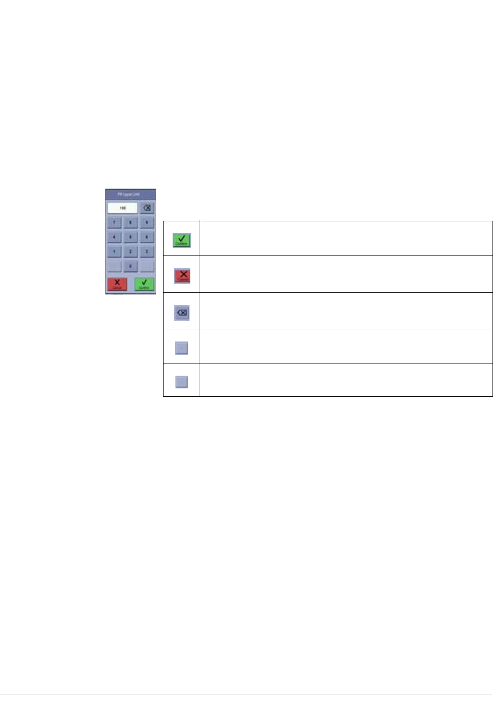
3-12 VC150 Vital Signs Monitor KO00065K
Getting started: Configuration mode settings
Configuration mode settings
Clinical defaults such as Upper/Lower alarm limits are set up in configuration
mode and can be changed as needed for a given patient in the Alarm Setup
screen. The limit settings always revert to the configured defaults when the
power is cycled or a new patient is identified. To retain alarm and parameter
settings, the changes must be done in configuration mode.
Using the numeric keypad
The numeric keypad can be used to enter numeric values, for example, in an
alarm limit box.
A numeric entry is accepted with Confirm.
An numeric entry is canceled with Cancel.
Backspace icon.
Dash icon.
Decimal comma icon.
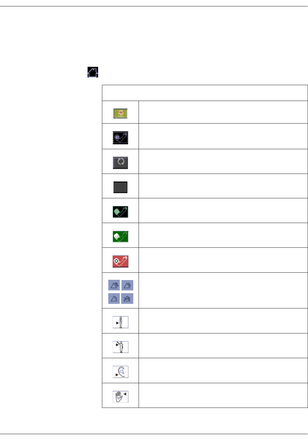
KO00065K VC150 Vital Signs Monitor 3-13
Getting started: Icons on the monitor
Icons on the monitor
Using the home icon
Whenever the home icon is selected, the system will save changes and return to
clinical mode.
List of VC150 icons
Alarm silenced
Auto mode options
Auto mode options not available
NIBP not available
Inflate
Inflate waiting
Stop inflation
Alarm priority
High/Medium/
Low/OFF
Rectal
Axillary
Earlobe
Finger
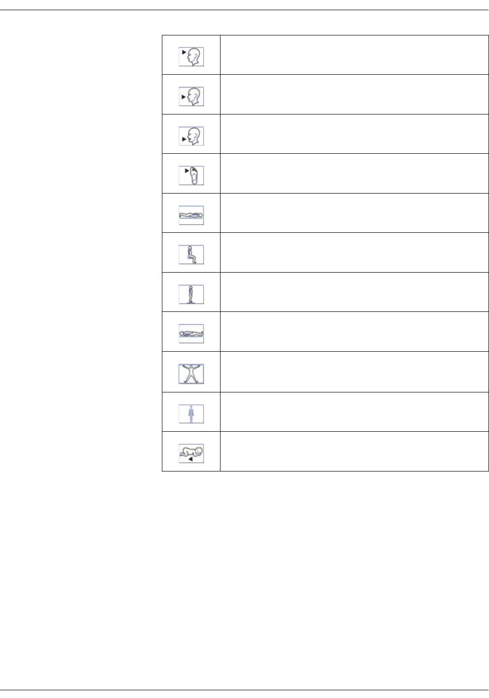
3-14 VC150 Vital Signs Monitor KO00065K
Getting started: Alarm limit setup
Alarm limit setup
There are two methods to set up alarm limits on individual parameter items.
These include selecting Alarm Setup or touching in the limit boxes within the
parameter.
NOTE
If priority for individual parameter items has been set as OFF in
configuration mode, the limit box will be dimmed in Alarm Setup and
cannot be changed.
Forehead
Nose
Oral
Toe
Prone position
Sitting position
Standing position
Supine position
Other site
None
Neonatal
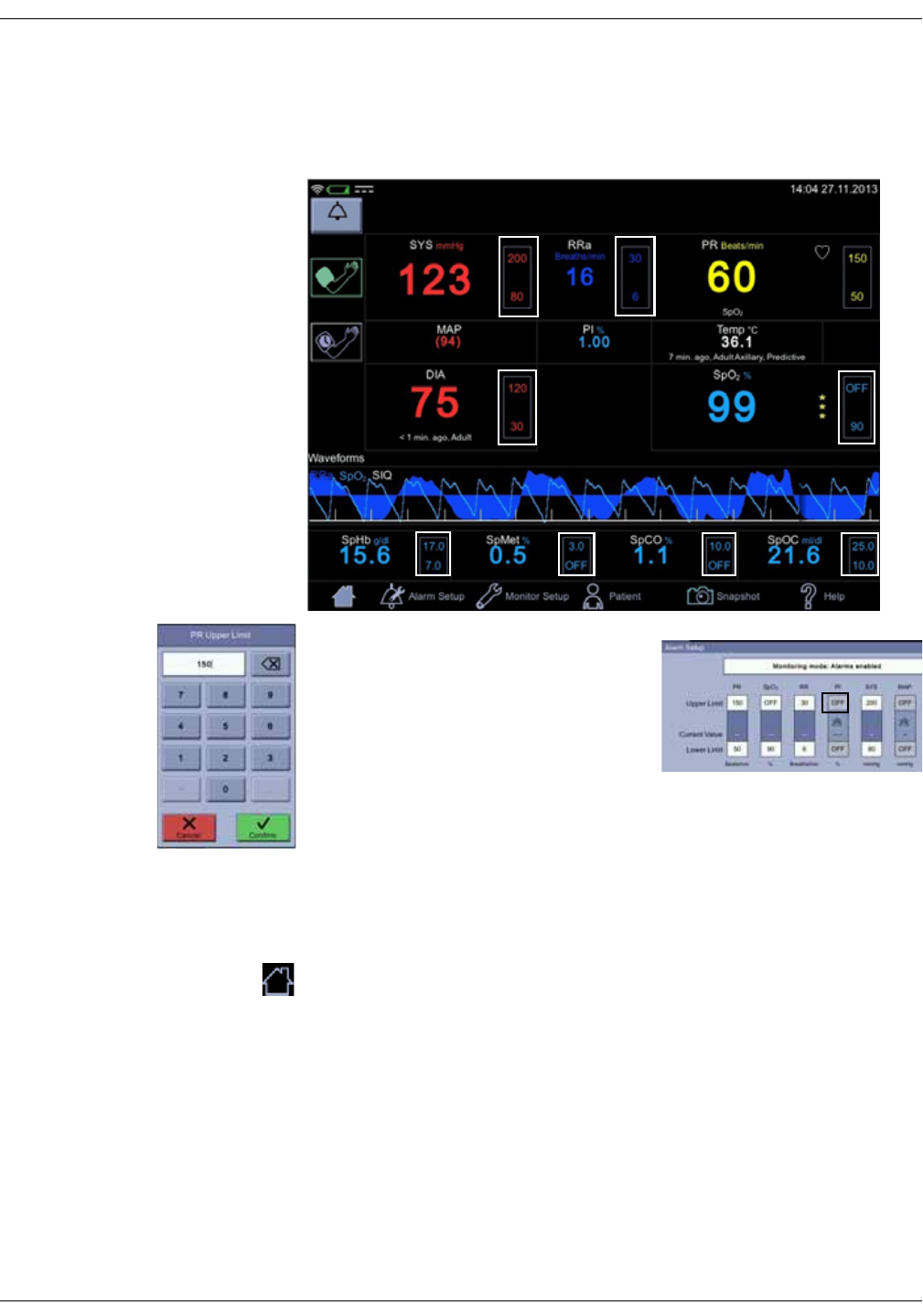
KO00065K VC150 Vital Signs Monitor 3-15
Getting started: Alarm limit setup
Changing limits for a single parameter box
1. Touch on the top or bottom part of the limit box to change high/low limits in
a single box.
2. Enter a value to set up or adjust a limit,
especially for neonates and children. A
value between upper and lower limits is
the Current Value of the parameter (the
sensors must be attached to the
monitor). It is provided to assist in setting
up or adjusting a limit.
NOTE
Adjust alarm limits cautiously.
3. Select Confirm key to confirm the change or select Cancel to cancel the
change.
4. Adjust other limits if necessary.
5. When you are finished with the alarm setup, select the home icon to save
the settings and return to clinical mode.
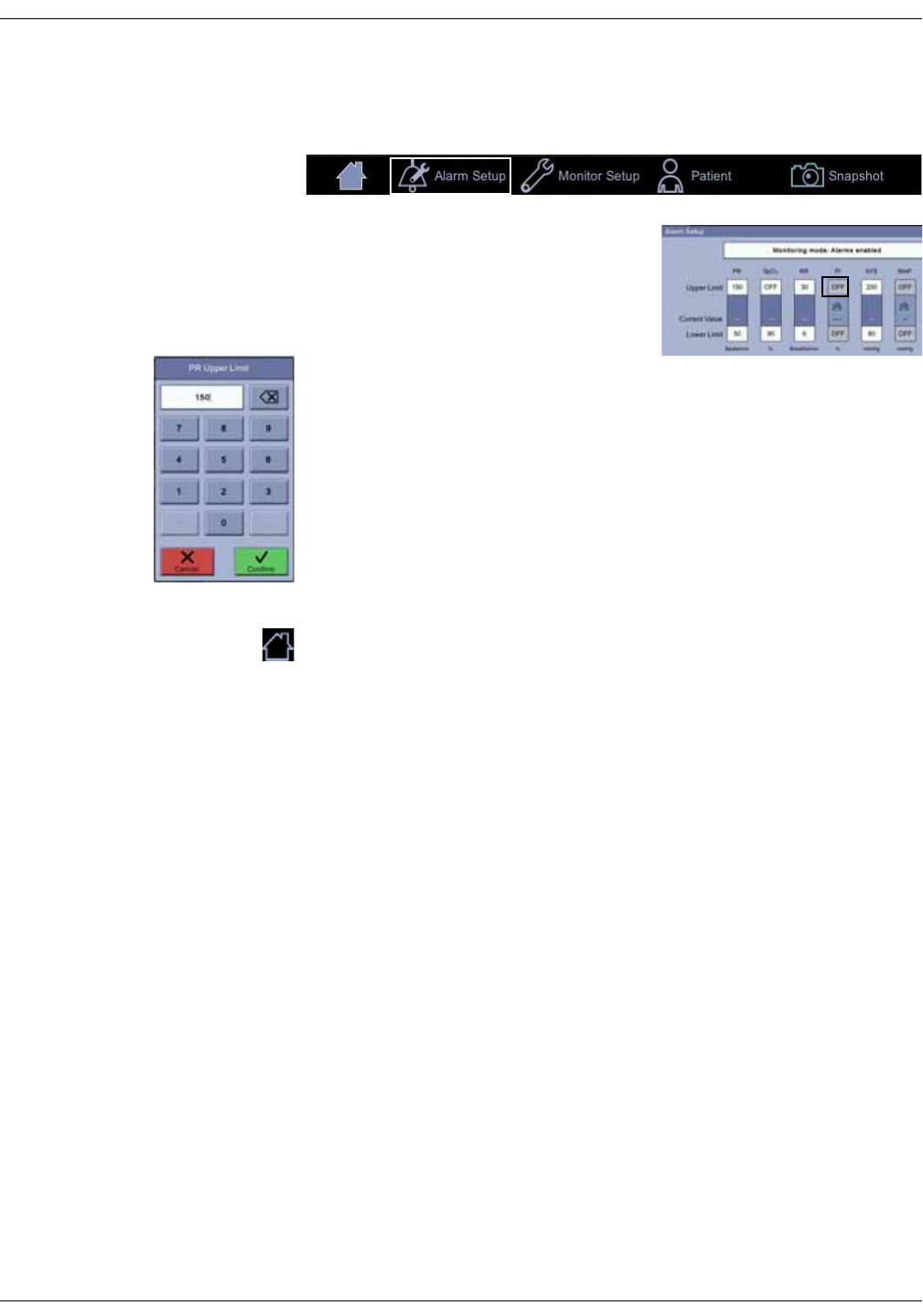
3-16 VC150 Vital Signs Monitor KO00065K
Getting started: Alarm limit setup
Changing multiple alarm limits
1. Select Alarm Setup.
2. This screen will appear. Available limits
vary depending on purchased licenses
or SpO2 technology used and what has
been selected in Monitor Setup > SpO2
or Monitor Setup > Default Setup >
Visual Settings.
3. Touch on the top or bottom part of the limit box.
4. Enter a value to set up or adjust a limit, especially for neonates and children.
A value between upper and lower limits is the Current Value of the
parameter (the sensors must be attached to the monitor). It is provided to
assist in setting up or adjusting a limit.
NOTE
Adjust alarm limits cautiously.
5. Select Confirm to confirm the change or select Cancel to cancel the change.
6. Adjust other limits if necessary.
7. When you are finished with the alarm setup, select the home icon to save
the settings and return to clinical mode.
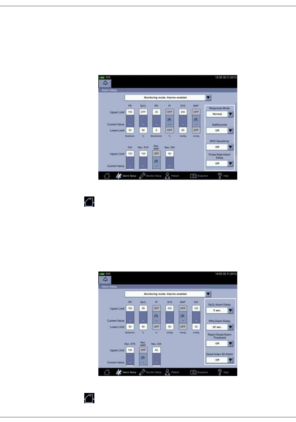
KO00065K VC150 Vital Signs Monitor 3-17
Getting started: Nellcor feature setup
Nellcor feature setup
Refer to “Nellcor SpO2 configuration” on page 9-27 for more information on
Nellcor features.
1. Enter Alarm Setup.
2. Make the necessary selections.
3. Select the home icon to save the settings and exit the Alarm Setup.
Masimo feature setup
Refer to “Masimo rainbow® SET® SpO2 configuration” on page 8-25 for more
information on Masimo features.
1. Enter Alarm Setup.
2. Make necessary selections.
3. Select the home icon to save the settings and exit the Alarm Setup.
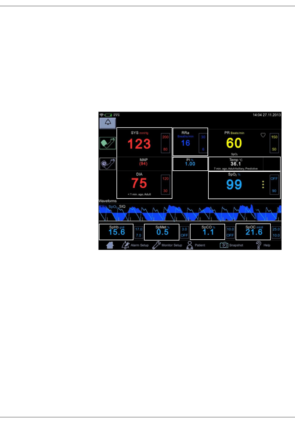
3-18 VC150 Vital Signs Monitor KO00065K
Getting started: Monitor setup
Monitor setup
Monitor setup allows you to select options or modify settings. When selected, the
Monitor Setup icon is highlighted. There are 4 tabs for a normal user to choose
from: Audible & Visual, NIBP, SpO2 or Temperature.
Shortcut to setup screens
1. If you select a touch screen item (except for PR), a shortcut will take you to
menu screens where you can select options or modify settings.
2. When you are finished with the configuration, select the home icon to return
to clinical mode.
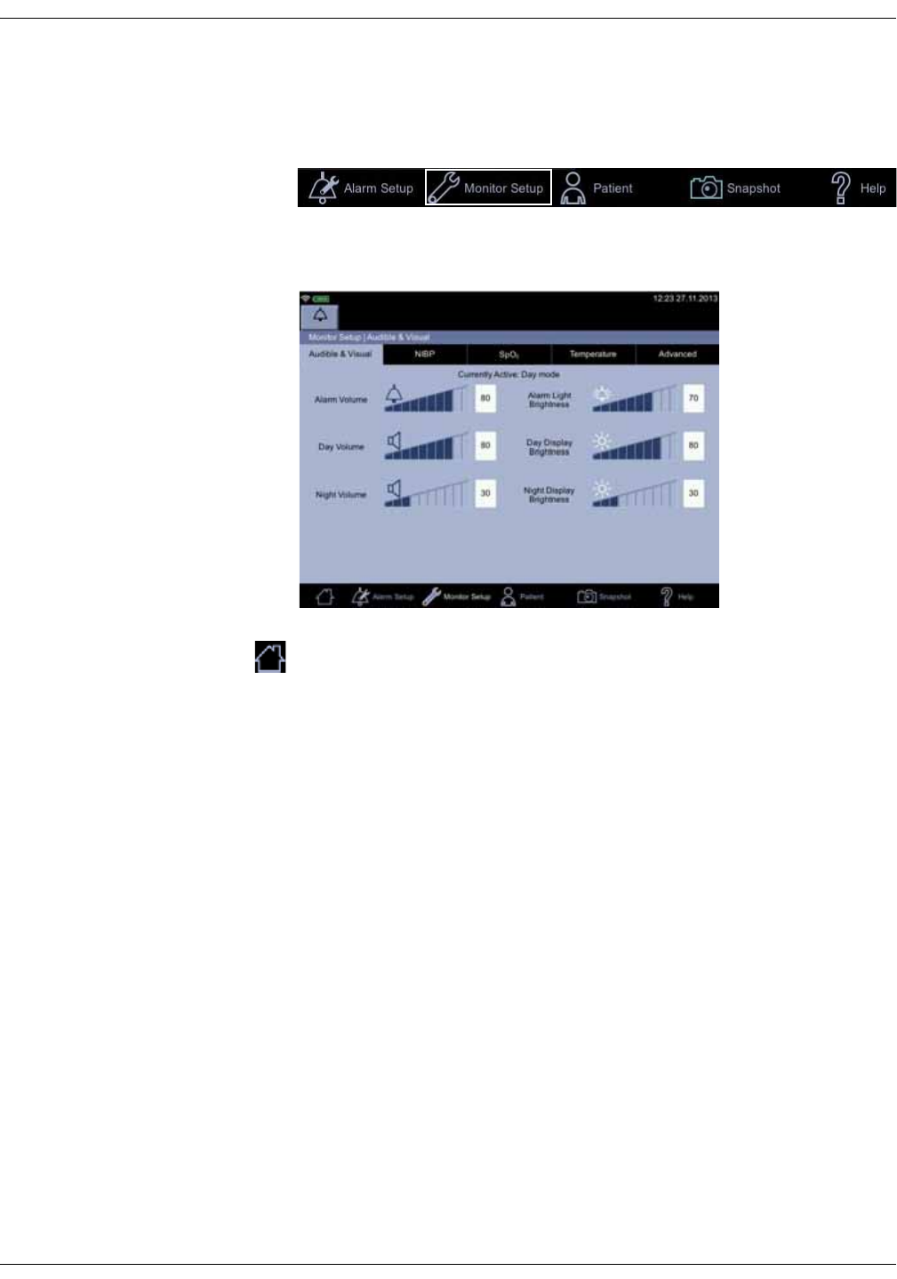
KO00065K VC150 Vital Signs Monitor 3-19
Getting started: Menu selection for setup screens
Menu selection for setup screens
1. Select Monitor Setup and subsequent tab sheets.
2. Select Audible & Visual, NIBP, SpO2 or Temperature to make selections or to
modify the settings.
3. When you are finished with the configuration, select the home icon to return
to clinical mode.
Audible & Visual
An audible signal is used to indicate the presence of an alarm limit violation. If
audible signals need adjustment, these can be adjusted in the Monitor Setup >
Audible & Visual screen.
The first tab in Monitor Setup is Audible & Visual. This allows you to adjust
Alarm Volume, Day Volume, Night Volume, Alarm Light Brightness, Day
Display Brightness and Night Display Brightness. The currently active day/
night mode is automatically determined by a light sensor on lower right part of
the monitor touch screen. The tab sheet displays the mode for both volume and
brightness above sound level bars. Sound levels can be lowered by selecting left
part of the sound level bar or raised by selecting the right part of the sound level
bar. These settings affect all applicable monitor screens. If the alarm sound level
cannot be set as low as required, it means that the minimum alarm sound level
has been set in the Monitor Setup > Advanced > Default Setup > General to be
something other than 0.
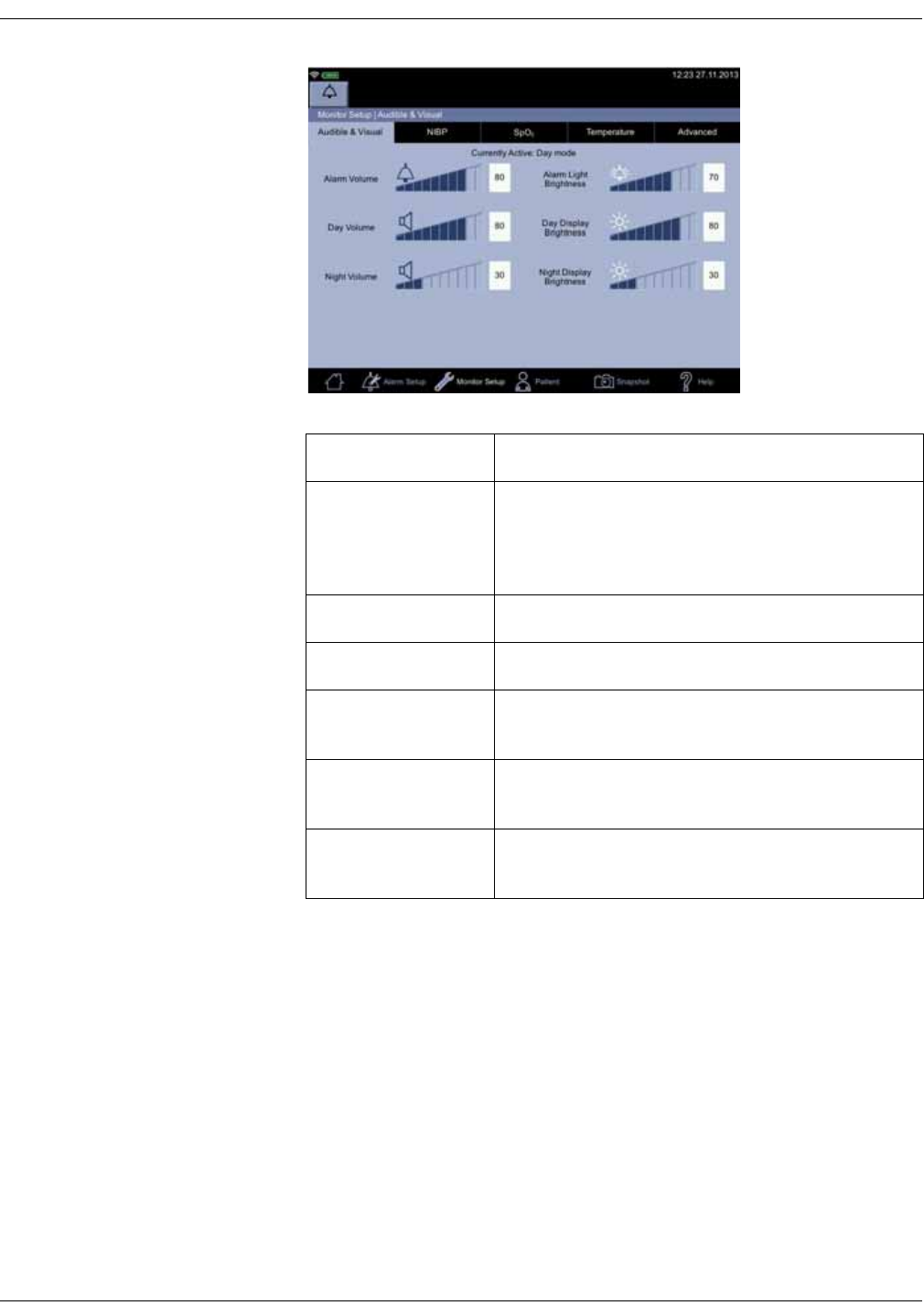
3-20 VC150 Vital Signs Monitor KO00065K
Getting started: Menu selection for setup screens
Signal Description
Alarm Volume
Controls the level of audible alarm signal at the
monitor. Minimum Alarm Volume in configuration
mode sets the relative lower limit, but you can adjust
the sound here from 0 to 100.
Day Volume Controls the sound level during day time use.
Night Volume Controls the sound level during night time use.
Alarm Light
Brightness Controls the illumination level of the LEDs when an
alarm message is triggered on the screen.
Day Display
Brightness Controls the level of backlight on the monitor during
the daytime.
Night Display
Brightness Controls the level of back light on the monitor during
the nighttime.
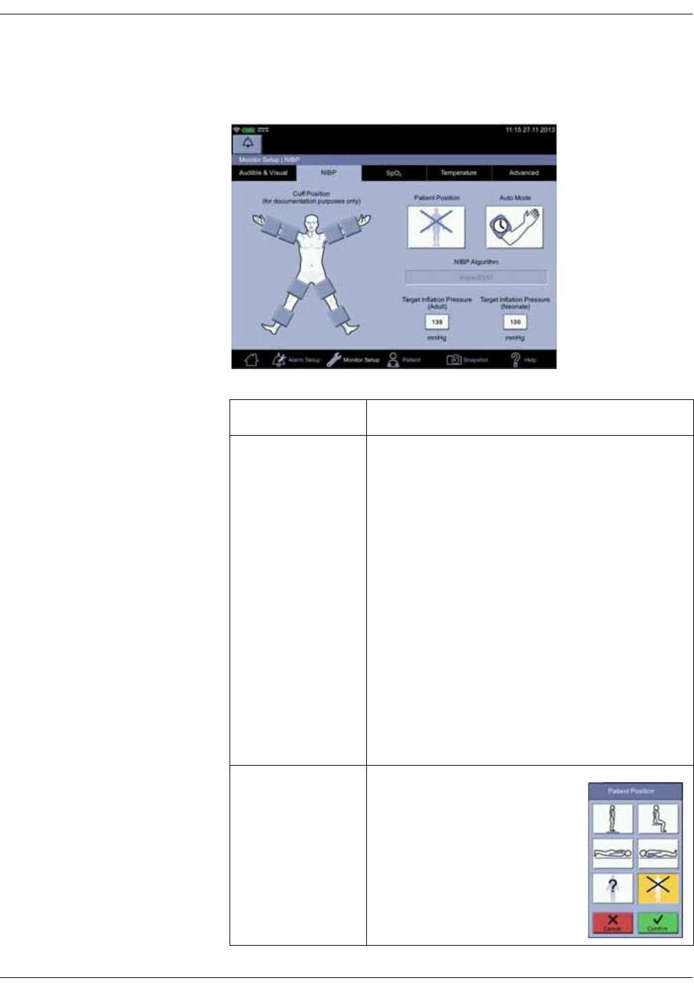
KO00065K VC150 Vital Signs Monitor 3-21
Getting started: Menu selection for setup screens
NIBP setup
The second tab in Monitor Setup is NIBP.
NIBP settings Description
Cuff position and
side Rectangular sections indicate areas on the body
where the cuff can be placed for NIBP measurement.
Only one cuff position can be selected at the time.
When a rectangle is selected, it will turn dark. If the
measurement site needs to be changed, select
another rectangle. If you want to cancel selection of a
measurement site, select a dark rectangle to deselect
it.
The selected cuff position will be displayed below the
diastolic value.
NOTE
Choosing the position of the cuff is for
documentation purposes only. Whatever is
selected here does not have any effect on the
operation of the NIBP measurement system.
Please refer to the instructions for use of the cuff
for further information.
Patient position An optional selection of patient
position during measurement.

3-22 VC150 Vital Signs Monitor KO00065K
Getting started: Menu selection for setup screens
NIBP algorithm Indicates the NIBP algorithm in use. Service can
change it upon request.
Target Inflation
Pressure Adult
Target Inflation
Pressure Neonate
Target inflation pressure is a level of pressurization
that the monitor aims for when a new determination
is initiated. If the patient's usual systolic value is
known, a normal end user can change the target
pressure to provide extra comfort. Changing this
setting for either patient type is possible when no
NIBP determination is active. When the patient is
discharged, the monitor will revert to the default
target pressure. If the monitor detects a different
hose, it will revert to the most recent default target
inflation setting for that hose type. The default target
inflation pressure can be adjusted in configuration
mode if necessary.
Initial default target pressures:
• Adults/children when auscultatory algorithm is
used: 160 mmHg/21.33 kPa
• Adults/children when SuperSTAT algorithm is used:
135 mmHg/18.00 kPa
• Neonates, SuperSTAT algorithm: 100 mmHg/13.33
kPa
Setting range for systolic target cuff pressure:
• Adults/children: 100 to 250 mmHg (13.3 to 33.3 kPa)
• Neonates: 70 to 140 mmHg (9.3 to 18.7 kPa)
NIBP settings Description
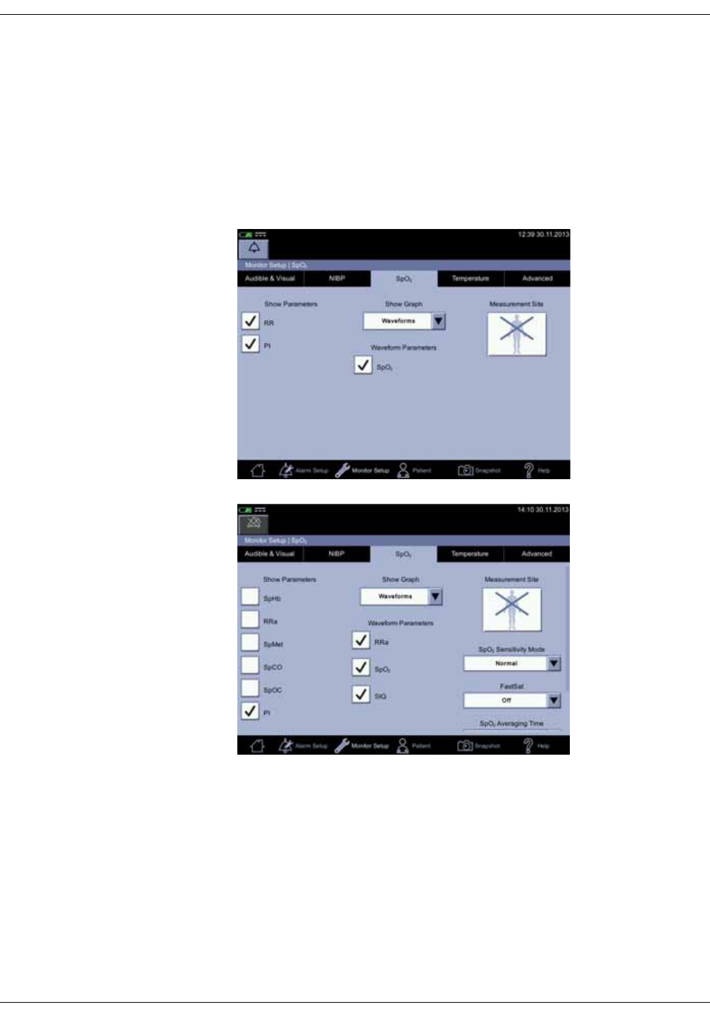
KO00065K VC150 Vital Signs Monitor 3-23
Getting started: Menu selection for setup screens
SpO2 setup
The third tab under Monitor Setup is SpO2. Menu selections for SpO2 differ
depending upon the technology (GE TruSignal, Nellcor, or Masimo) used. Refer to
“GE TruSignal SpO2” on page 7-1, “Masimo SpO2” on page 8-1 or “Nellcor SpO2”
on page 9-1 for technology-specific options.
More Nellcor, GE TruSignal and Masimo settings as well as alarm limits can be
set in configuration mode. For all other setup issues, contact service.
Masimo
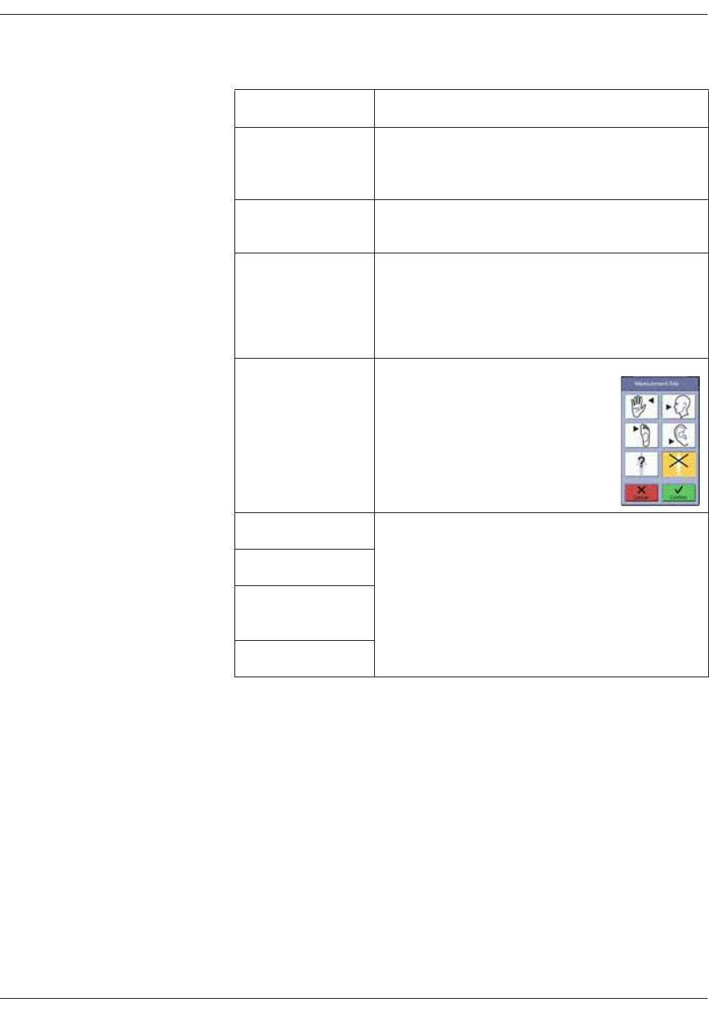
3-24 VC150 Vital Signs Monitor KO00065K
Getting started: Menu selection for setup screens
SpO2 screen options Description
SpHb, RR, RRa,
SpMet, SpCO, SpOC,
PI
If checked, the option will be shown on screen.
Availability of the options depends on the SpO2
technology used.
Show Graph If Waveforms is selected, the monitor will display a
parameter waveform on screen.
Waveform
parameters Selection of SIQ or RRa (Masimo), or SpO2 (TruSignal,
Masimo and Nellcor) for waveform display. One, two
or all of these can be displayed at the same time.
Deselection of a waveform parameter removes it
from the screen display.
Measurement Site Selection for the part of the patient’s
body where SpO2 sensor is located.
Sensitivity Mode Refer to “Masimo rainbow® SET® SpO2
configuration” on page 8-25 for more information on
optional Masimo features available if licenses for
these were purchased with the unit or afterwards.
FastSat
SpO2 Averaging
Time
RRa Averaging Time
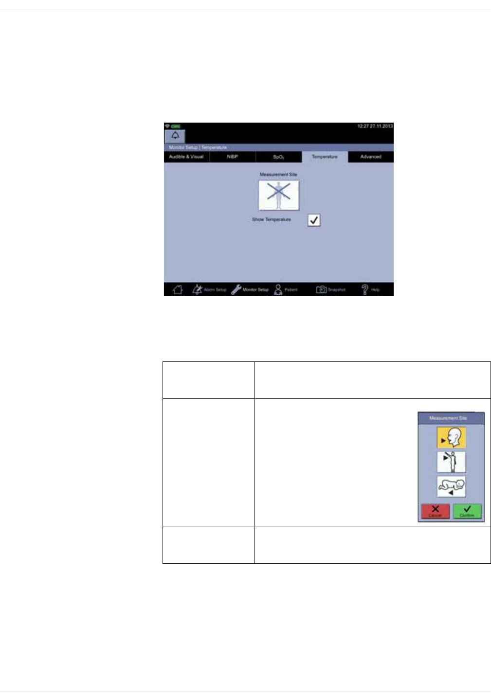
KO00065K VC150 Vital Signs Monitor 3-25
Getting started: Menu selection for setup screens
Temperature setup
The fourth tab under Monitor Setup is Temperature. If the monitor is equipped
with the Exergen temperature technology and Show Temperature check box is
selected, the temperature parameter on the home screen is displayed and vice
versa.
If the monitor is equipped with Welch Allyn temperature technology, the check
box is disabled and the temperature parameter is always displayed on the home
screen.
Advanced
The fifth tab under Monitor Setup is Advanced, which consists of three login
boxes. Password-protected Default Setup is intended for someone at the
hospital or care unit that has the training and authority to configure default
settings for the monitor. Password-protected Service Mode is intended only for
service personnel. Start Remote Service is activated by the nurse manager or
the service and thereafter intended only for the service personnel.
Temperature
options Description
Measurement Site Selection for the part of the patient’s
body where temperature is
measured. Availability of the sites
depends on the temperature
technology used.
Show Temperature
(Exergen only)
If checked, the temperature parameter is displayed on
the screen.
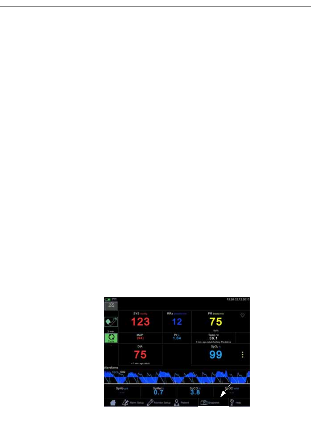
3-26 VC150 Vital Signs Monitor KO00065K
Getting started: Patient
Patient
Refer to “Patient and caregiver data” on page 5-1 for information on admitting
or discharging a patient.
Patient identification
Before taking any measurements on a patient, identify the patient as instructed
in “Selecting or adding a patient” on page 5-6. This helps avoid risk of assigning
snapshots to the wrong patient. Patient identification can be done later as well,
but you cannot send the snapshots to the hospital EMR before the patient is
identified. If hospital policy requires a positive patient identification, refer to
“Positive patient identification” on page 5-9.
Snapshot
Vital signs data can be captured as a snapshot and stored in patient data. Some
measurements are stored automatically. Refer to “Patient and caregiver data”
on page 5-1 for more on snapshots. The monitor stores the snapshot in a list of
patient data entries in Patient for viewing, printing or sending out to the EMR.
Select Snapshot to capture measurement values. When the values are
captured, the background for screen values will turn gray for a short moment
and two short beeps are signaled.
NOTE
NIBP values, Exergen values and Welch Allyn predictive measurement
values are automatically stored in patient data when the measurement is
complete. There is no need to select Snapshot for these values.
If you want to store all active measurement values when the NIBP
measurement is complete, ask the nurse manager or service to select
Snapshot upon NIBP completion in configuration mode.

KO00065K VC150 Vital Signs Monitor 3-27
Getting started: Help
Help
Selected sections of this operator’s manual can be accessed in the Help menu.
Select Help to access an index page where you can scroll through the content.
You can use the Back and Forward keys to move between pages. Select Close to
exit help.

3-28 VC150 Vital Signs Monitor KO00065K
Getting started: Help
This page is intentionally left blank.

KO00065K VC150 Vital Signs Monitor 4-1
4Alarms

4-2 VC150 Vital Signs Monitor KO00065K
Alarms: Description
Description
Physiological alarms are active only in monitoring mode, not in spot-check
mode. Alarm condition notifications include:
• An LED light on the top of the monitor.
• An audible alarm signal (always with high or medium priority level alarms,
can be enabled/disabled in configuration mode for low priority alarms).
• The parameter display is highlighted for the parameter causing the alarm
(parameter value with priority color on the background).
• A note under the parameter value (technical conditions only). If the status of
the measurement is abnormal, then white text indicating the issue will
appear below the parameter value. If the abnormal state remains for 10
seconds, then a blue or yellow (low or medium priority) alarm is generated.
• Alarm message text displayed in the notification area at the top of the
screen.
WARNING
Do not silence or disable audible alarms or decrease the volume of the
audible alarm if patient safety could be compromised. Do not dim or
disable visual alarms if patient safety could be compromised.
Alarm types
Physiological alarms
When a patient‘s vital signs are above an upper parameter limit or below a lower
parameter limit, a physiological alarm is invoked. The monitor checks each
derived vital sign (except temperature) against user-set limits. A high limit alarm
is generated when a value exceeds a high limit. A low limit alarm is generated
when a value is less than a low limit.
Technical alarms
When an electrical or mechanical failure of the equipment, loss of measurement
data, or a sensor or component failure happens, a technical alarm is invoked in
the notification area. Technical alarms may also be displayed when an algorithm
cannot classify or interpret the available data.
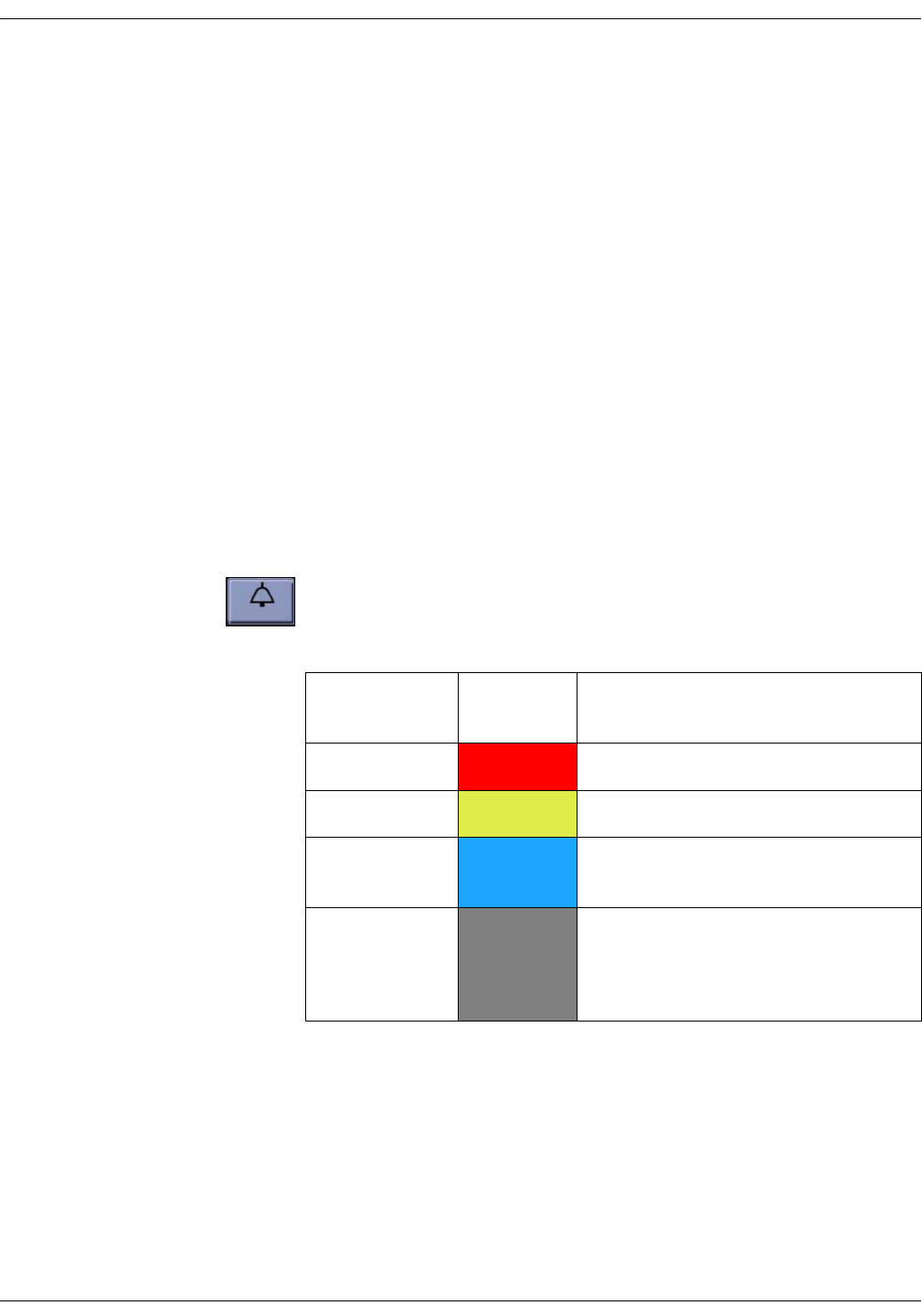
KO00065K VC150 Vital Signs Monitor 4-3
Alarms: Alarm signals
Battery alarms
The monitor can display alarms for low charge, depleted battery or a battery
problem. Refer to “Battery” on page 13-1 for more on battery operation. There
are two alarms indicating that the battery is low.
• Low priority alarm Battery Low when there is power left for approximately
10 NIBP determinations.
• High-priority alarm Battery Low when there is power left for approximately
5 minutes of operation.
NOTE
When the battery is nearly depleted, the monitor displays a high priority
alarm message in the notification area. Once this message appears on
screen, there are 5 minutes of operation time left. NIBP measurement or
printouts with the strip printer are not allowed anymore. Five minutes after
the message appears, the monitor will terminate active operations and shut
down.
Alarm signals
The monitor provides visual and audible alarm signals when an alarm condition
is present unless an alarm is silenced for 2 minutes with the silence icon. Other
audible signals remain enabled. Refer to “Alarm silence indicator” on page 4-5.
NOTE
Selecting the silence icon does not acknowledge the alarm. It just silences
the audible signal.
Priority
level Highlight
color Description
HIGH RED Requires an immediate response.
MEDIUM YELLOW Requires a prompt response.
LOW BLUE Requires the user to be aware of this
condition.
NOTIFICATION GRAY Provides additional information. No
assigned priority. In some cases, the
message is also shown as low priority text
in the applicable parameter area.
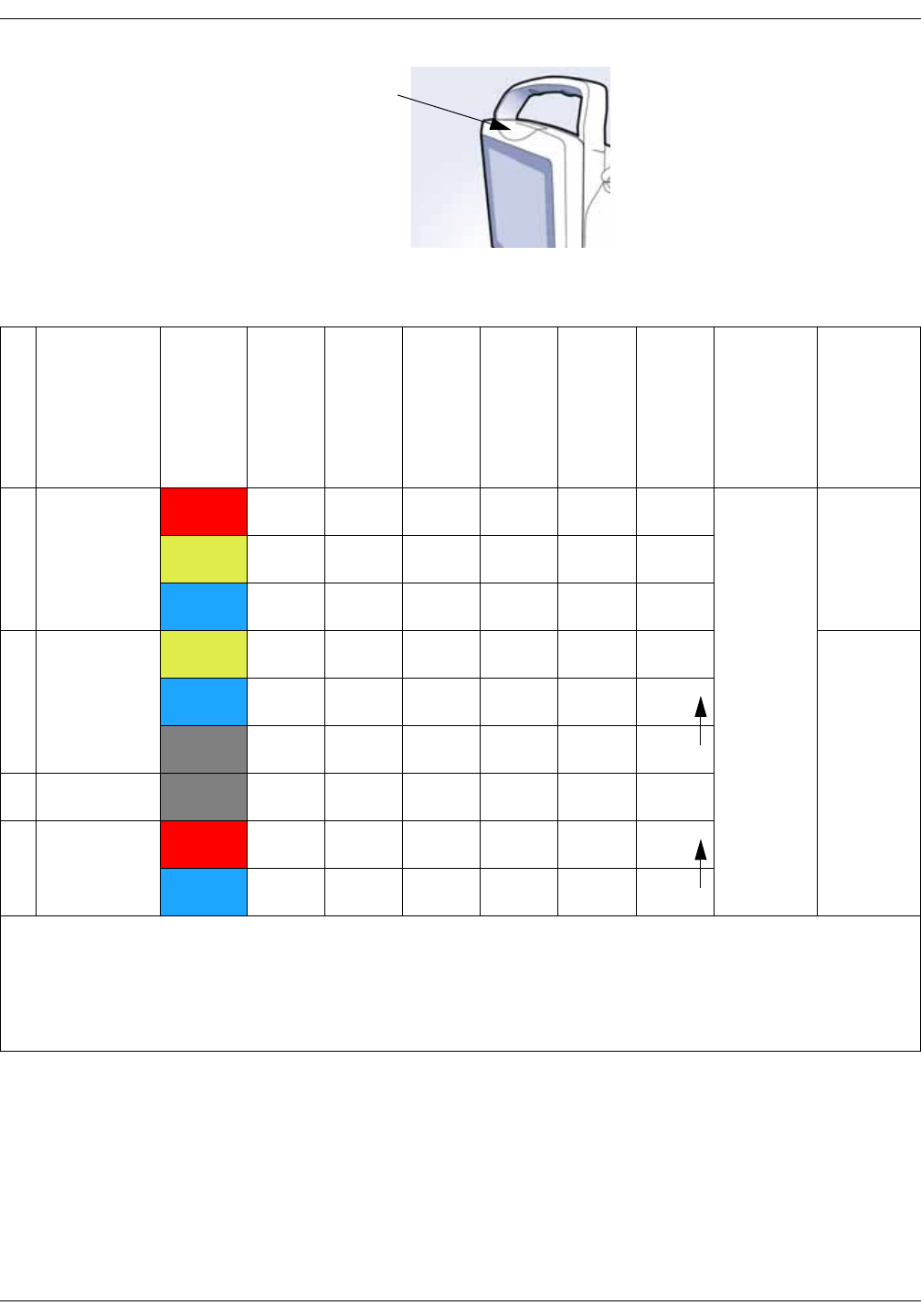
4-4 VC150 Vital Signs Monitor KO00065K
Alarms: Alarm signals
When multiple alarm conditions occur at the same time, the monitor will sound
an alarm tone for the highest priority alarm. Any lower priority alarm is
superseded by the higher priority alarm. If the high priority alarm is cleared, but
the lower priority alarm condition still remains, the monitor goes back to
sounding the lower priority alarm.
NOTE
Alarm priorities can be adjusted in configuration mode.
LED alarm
light
Alarm
type
Alarm
priority color
LED
Message blinks
on screen
Parameter
field highlighted
Alarm
sound1
Notification in
parameter field
Escalation
Monitoring mode
Spot-check mode
1 Clinical2Red Yes Yes Yes Yes No No Enabled Disabled
Yellow Yes Yes Yes Yes No No
Blue Yes No Yes Yes3No No
2 Technical Yellow Yes Yes No Yes No No Enabled
Blue Yes No No Yes3No No
Gray No No No Yes Yes4Yes5
3System Gray No No No Yes No No
4 Battery Red Yes Yes No Yes No No
Blue Yes No No Yes3No Yes5
1 For description of beeps, refer to the table in the Alarm tones section.
2 Clinical alarms are not active in spot-check mode.
3 Low priority alarm sounds can be silenced if required. Refer to “Alarm silence indicator” on page 4-5 for instructions.
4 Some alarms.
5 Refer to “Escalation of an alarm condition” on page 4-6.
KO00065K VC150 Vital Signs Monitor 4-5
Alarms: Alarm signals
Alarm tones
The high-pitched, continuous battery low shutdown alarm tone sounds cannot
be silenced. Sounds related to low priority alarms can be silenced in
configuration mode. Do not silence the alarm unless specifically requested by
the care unit.
Alarm silence indicator
To silence an alarm (physiological or technical) at any time, select the silence
icon. The alarm bell icon will turn red. When two minutes of silence expires, the
alarm sounds again, unless the alarm condition has cleared out. If latching is
selected, the alarm message will be displayed even though the alarm condition
has cleared out. The message must be acknowledged.
The alarm silence indicator has two states:
• Red alarm bell: Alarm silence is active and the audible alarm tones are
silenced for 2 minutes. A countdown timer underneath the indicator
displays the remaining time for the silence.
• Off: Alarm silence is not active.
NOTE
In spot-check mode, this icon is replaced by the alarm off symbol.
Priority Sound Beeps
High Yes 10 beeps in series of
3-2-3-2, repeated every 15 sec.1
Medium Yes 3 beeps every 15 seconds
Low Yes
(if enabled in
Default Setup)
1 beep
every 15 seconds
Technical Yes 2 short beeps
1 Alarm tone patterns repeat continuously until silenced, acknowledged or the
condition causing the alarm is removed.
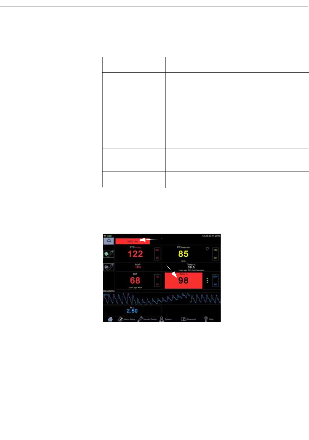
4-6 VC150 Vital Signs Monitor KO00065K
Alarms: Alarm signals
Escalation of an alarm condition
Alarms may be escalated in some cases.
Flashing parameter numbers
With a high-priority clinical alarm, the parameter field lights up and the message
in the notification area blinks to attract attention.
Alarm type Level of escalation
Physiological alarms None
Battery charge
alarms
The monitor asserts a low priority alarm when the
battery has enough power for approximately 10
NIBP determinations.
The monitor asserts a high priority alarm when the
battery has enough power for approximately 5
minutes of operation.
Technical
notifications
The monitor escalates an abnormal technical status
to a low priority alarm after 10 seconds.
System notifications None

KO00065K VC150 Vital Signs Monitor 4-7
Alarms: Alarms and priorities
Remote alarms
A remote alarm activates when any medium or high priority alarm or system
failure alarm is active, or if the monitor is powered off. The remote alarm signal
tracks the state of alarms asserted locally at the monitor. Whenever an alarm is
being sounded, the remote alarm is also asserted. Refer to “Connections” on
page A-2 for additional information on the remote alarm.
When a medium or high priority alarm condition is displayed on the monitor, the
remote alarm signal becomes active. The active state of the alarm signal is an
open circuit. In the inactive state the alarm signal is connected to ground.
NOTES
The primary method of asserting alarms is always locally by the monitor
itself. The remote alarm should only be considered a supplemental method
of asserting alarms.
The monitor does not support Hostcomm 1846 communication protocol.
Acknowledging an alarm
The alarm message is acknowledged by selecting the message in the
notification area on top of the screen. The error message disappears, but the
parameter area will be highlighted as long as the error condition exists. Audible
and visible alarms disappear automatically when an alarm condition no longer
exists, unless latching is selected.
For a list of acknowledgeable alarms, refer to “Alarms and priorities” on page 4-
7.
Alarms and priorities
The following tables list physiological and technical alarm conditions for the
VC150 monitor. Messages are either alarms or informative ones.

4-8 VC150 Vital Signs Monitor KO00065K
Alarms: Alarms and priorities
Physiological alarm conditions
Alarm condition Alarm limit range Factory
default limit Factory
default priority
NIBP Systolic High (adult/pediatric) 35 to 290 200 mmHg Medium
NIBP Systolic High (neonates) 35 to 140 100 mmHg
NIBP Systolic Low (adult/pediatric) 30 to 285 80 mmHg
NIBP Systolic Low (neonates) 30 to 135 40 mmHg
NIBP Diastolic High (adult/pediatric) 15 to 220 120 mmHg
NIBP Diastolic High (neonates) 15 to 110 60 mmHg
NIBP Diastolic Low (adult/pediatric) 10 to 215 30 mmHg
NIBP Diastolic Low (neonates) 10 to 105 20 mmHg
MAP high (adult) 25 to 260 Off1Off1
MAP high (neonate) 25 to 125
MAP low (adult) 20 to 255
MAP low (neonate) 20 to 120
SpO2 High 71 to 99 Off Medium
SpO2 Low 70 to 98 90%
Pulse Rate High 35 to 235 150 beats per minute Low
Pulse Rate Low 30 to 230 50 beats per minute
Perfusion Index High GE TruSignal:
0.3 to 31.8%
Masimo and Nellcor:
0.3 to 19.0%
Off Off
Perfusion Index Low GE TruSignal:
0.2 to 31.7%
Masimo and Nellcor:
0.2 to 18.0%

KO00065K VC150 Vital Signs Monitor 4-9
Alarms: Alarms and priorities
Acoustic Respiration Rate High2
(Masimo)
5 to 69 30 breaths per minute Medium
Acoustic Respiration Rate Low2
(Masimo)
4 to 68 6 breaths per minute
Acoustic Respiration Rate Timeout20, 1, 5, 10 or 15 minutes 5 minutes
Respiration Rate High2 (Nellcor) 5 to 40 30 breaths per minute
Respiration Rate Low2 (Nellcor) 4 to 39 6 breaths per minute
Saturation Pattern Detection, SPD2Off/Most sensitive/
Moderately/Least
Off
SpMet High2 (Masimo) 1.0 to 99.5 3.0
SpMet Low2 (Masimo) 0.2 to 99.0 Off
SpCO High2 (Masimo) 2.0 to 98.0 10.0
SpCO Low2 (Masimo) 1.0 to 97.0 Off
SpHb High2 (Masimo) 2.0 - 24.5 g/dl or
2.0 - 15.0 mmol/l
17.0 g/dl or
11.0 mmol/l
Low
SpHb Low2 (Masimo) 1.0 - 23.5 g/dl or
1.0 - 14.5 mmol/l
7.0 g/dl or
4.0 mmol/l
SpOC High2 (Masimo) 2.0 - 34.0 mL O2/dl blood 25.0 O2/dl blood
SpOC Low2 (Masimo) 1.0 - 33.0 O2/dl blood 10.0 O2/dl blood
3D Desaturation Index Multiple selectable
settings, please see SpO2
section for Masimo
-Off
3D Perfusion Index Delta
1 MAP alarm can be enabled in Default Setup > Alarm Defaults
2 Licensed feature, availability depends on the OEM measurement module hardware.
To change alarm default settings, refer to “Alarm defaults” on page 14-4.
Alarm condition Alarm limit range Factory
default limit Factory
default priority

4-10 VC150 Vital Signs Monitor KO00065K
Alarms: Alarms and priorities
Technical alarm conditions
Technical alarm conditions
Message in the
notification area Possible cause/description/action
Battery messages
Battery Low • When a low priority alarm, this indicates that there is
enough power left for approximately 10 NIBP
measurements.
• When a high-priority alarm, this indicates that the
monitor will stop all processes and shut down after
approximately 5 minutes after this alarm. NIBP
measurements and printing are disabled from now
on.
Host software messages
Audio not
available • Audio cannot be played by the speaker inside the
monitor case. Potential hardware problem.
•Contact service.
Battery not
connected • Please contact service.
• Displayed as a full screen message when battery is
removed or broken. Contact service.
Cannot connect to
remote server • Authentication of patient data query failed due to
connection error to remote host.
• Authentication of the caregiver ID failed due to
connection error to remote host.
•Contact service.
Caregiver
authentication
failed
• Authentication of the caregiver failed due to wrong
password or unknown username.
• Enter the username and password and try again to
authenticate.
Caregiver ID
requires validation • Validated caregiver ID is required to send a record to
EMR, but the caregiver ID is not validated.
• Caregiver authentication is required to make a
patient demographics query.
Caregiver ID
required • An attempt was made to send an EMR record
without a valid caregiver ID.
• Provide a valid caregiver ID.
Failed to update
time • System time not received from the NTP server.
Potential network error.
•Contact service.

KO00065K VC150 Vital Signs Monitor 4-11
Alarms: Alarms and priorities
Internal Bus
Communication
Failure
Please contact
Service
• Internal problem. Contact service. If the problem
persists, do not use the monitor.
Invalid EMR
Encoding • Hospital-specific EMR settings are not valid.
•Contact service.
Invalid
Identification •Incorrect ID due to missing or incomplete ID or
missing password.
• Enter the identification and the password again.
Invalid SSL
configuration • Authentication of a patient data query failed due to
SSL error.
• Authentication of the caregiver ID failed due to SSL
error.
•Contact service.
Local History
Reset • Local history database is reset.
Local History
Unavailable • Storage of patient data to local history database
failed. Storage space may be full.
•Contact service.
Local History Unit
Error • Storage of physiological measurement to the local
history database failed due to changed unit of
measurement. Only one unit per type of
measurement is allowed in the database.
• Delete patient history as instructed in “Deleting
patient history” on page 5-21. When this is done,
restart measurements.
Patient ID requires
validation • Validated patient ID is required to send a record to
EMR, but the patient ID is not validated.
Patient ID required • An attempt was made to send a record to EMR
without a valid patient ID.
Patient will be
discharged if time
is changed
• The user is about to change the system time.
• The user is informed that a patient will be discharged
if the system time is changed.
PM in N days • Preventive maintenance date will pass after N days
(where N = the number of days).
•Contact service.
Technical alarm conditions
Message in the
notification area Possible cause/description/action
4-12 VC150 Vital Signs Monitor KO00065K
Alarms: Alarms and priorities
PM passed N days
ago • Preventive maintenance date passed N days ago
(where N = the number of days).
•Contact service.
Printer error • Check the battery charge level.
• If the problem persists, contact service.
Printer out of
paper • Insert paper to the printer.
Printer
temperature • Let the printer cool down. If the problem persists,
contact service.
Send to EMR failed • Failure to send a record to the EMR due to a network
or other error.
•Contact service.
Settings changed • Service has performed remote management work
on the monitor.
Storage 100% full • Permanent storage partition volume is full.
•Contact service.
Storage 75% full • Permanent storage partition volume is nearly full.
Storage 90% full • Permanent storage partition volume is nearly full.
•Contact service.
System crash
detected • The system did not shut down correctly before the
latest restart.
USB not available • Restart the monitor. If the problem persists, contact
service.
USB <port
number>
overcurrent
• Connected USB device does not operate as it is
drawing excess amount of power. Contact service.
Technical alarm conditions
Message in the
notification area Possible cause/description/action

KO00065K VC150 Vital Signs Monitor 4-13
Alarms: Alarms and priorities
These messages are also shown under temperature value.
The scanner may also display additional indicators on the scanner’s LED
window.
Exergen messages
Message in the
notification area Possible cause/
description Action
Temp Battery Low • Battery low error • Replace the battery.
Temp Battery Empty • Battery fatal error
Temp Measurement
Too High • Target temperature
too high
• Check patient
condition.
Temp Measurement
Too Low • Target temperature
too low
Temp Ambient high • High ambient
temperature
• Cool down the
ambient room
temperature.
Temp Ambient low • Low ambient
temperature
• Warm up the ambient
room temperature.
LED window Condition Description/Action
HI Temperature too
high
> 43° C (110° F)
LO Temperature too low < 16° C (61° F)
HI A High ambient
temperature
> 40° C (104° F)
LO A Low ambient
temperature
< 16° C (61° F)
bAtt Low battery Replace battery soon.
4-14 VC150 Vital Signs Monitor KO00065K
Alarms: Alarms and priorities
(blank display) Dead battery Replace battery.
Err Processing error Unplug and plug the scanner
into the monitor. Contact
Innokas Medical or Innokas
Medical representative.
Masimo messages
Message in the
notification area Possible cause/description Action
Respiration Pause • A pause in respiration has
been detected.
• Check the patient.
• Adjust the sensor.
RRa Faulty Probe •Defective sensor/
adhesive sensor
• Replace sensor.
RRa Incompatible
Cable • Incompatible cable • Use the proper
Masimo cable.
• Replace cable.
RRa Incompatible
sensor • Incompatible sensor/
adhesive sensor
• Replace sensor.
RRa Interference
detected • Noise by moving patient
impedes measurement
• Ambient noise impedes
measurement
• Ask the patient
remain still.
• Check for sources of
ambient noise.
RRa No Cable
Connected • No cable connected
• Defective cable
• Disconnect and
reconnect cables.
• Replace cable.
RRa No Sensor
Connected • No sensor/adhesive
sensor connected
• Disconnect and
reconnect cables.
• Replace sensor.
RRa Not Available • SpO2 module malfunction • Contact service.
RRa Replace Cable • Cable life has expired
• Unrecognized cable
• Defective cable
• Sensor cable fault
• Replace cable.
LED window Condition Description/Action

KO00065K VC150 Vital Signs Monitor 4-15
Alarms: Alarms and priorities
RRa Replace
Sensor • Adhesive or reusable
sensor life has expired
• Unrecognized sensor
• Replace sensor.
RRa Sensor Off
Patient • Sensor is off patient • Apply sensor at the
appropriate location
or adjust the sensor.
SpO2 - SpO2 Only
Mode • SpO2 only mode • Apply sensor at the
appropriate location
or adjust the sensor.
SpO2 Demo mode • Demo mode • Contact service.
SpO2 Faulty Cable • Defective cable
• Sensor cable fault
• Replace cable.
SpO2 Faulty Probe •Defective sensor
• Unrecognized adhesive
sensor
• Replace sensor.
SpO2 Incompatible
Cable • Incompatible cable • Use proper Masimo
cable.
• Replace cable.
SpO2 Incompatible
Sensor • Incompatible sensor • Replace sensor.
SpO2 Interference
Detected • Nail polish
• Sensor too tight
• Incorrect sensor position
• Excess infrared light or
bright ambient lights
• Electrical/optical
interference
• Excessive ambient
temperature
• Remove nail polish.
• Loosen the sensor a
little.
• Reposition the sensor.
• Remove source of
infrared light.
• Adjust ambient
lighting.
• Clean sensor site.
• Cool down the site.
SpO2 No Cable
Connected • No cable connected • Connect cable.
• Disconnect and
reconnect cables.
Masimo messages
Message in the
notification area Possible cause/description Action

4-16 VC150 Vital Signs Monitor KO00065K
Alarms: Alarms and priorities
SpO2 No Sensor
Connected • No sensor/adhesive
sensor connected
• Disconnect and
reconnect cables.
• Replace sensor.
SpHb Not
Available • The selected sensor is not
capable of measuring
SpHb. The SpHb sensor
life is expired.
• SpHb parameter selected
for display.
• Select a sensor
capable of measuring
SpHb.
• Replace the sensor.
• Deselect SpHb in the
Monitor Setup, if you
do not want to use
this sensor. If SpHb is
never used, ask the
nurse manager or
service to deselect
SbHb in configuration
mode.
SpO2 Perfusion
Low • Low perfusion index
• Signal too weak
• Check the patient.
• Adjust the sensor.
• Move the sensor to
another site with
better perfusion.
• Refer to “Masimo low
perfusion” on page 8-
44.
SpO2 Pulse Search • Pulse cannot be
determined
• Check the patient.
• Adjust the sensor.
SpO2 Replace
Cable • Cable life has expired
• Unrecognized cable
• Defective cable
• Replace cable.
SpO2 Replace
Sensor • Sensor/adhesive sensor
life has expired
• Defective adhesive or
reusable sensor
• Unrecognized sensor
• Replace sensor.
SpO2 Sensor Off
Patient • Sensor is off patient • Apply sensor at the
appropriate location
or adjust the sensor.
Masimo messages
Message in the
notification area Possible cause/description Action

KO00065K VC150 Vital Signs Monitor 4-17
Alarms: Alarms and priorities
Time remaining on
SpHb sensor • Displays the remaining
lifetime of the SpHb
sensor.
• No action required.
Masimo
Informative messages
SpO2 Not Available
or
SpO2
Programming
Failed
or
SpO2 Invalid
system app
• SpO2 module malfunction • For Sp02 Not
Available: Restart the
monitor. If the
problem persists,
contact service.
• For other messages,
contact service.
Nellcor messages
Message in the
notification area Possible cause/description Action
SpO2 Faulty probe •Defective sensor
• Unrecognized sensor
• Replace sensor.
SpO2 Interference
Detected • Nail polish
• Sensor too tight
• Incorrect sensor position
• Excess infrared light or
bright ambient lights
• Electrical/optical
interference
• Remove nail polish.
• Loosen the sensor a
little.
• Reposition the sensor.
• Remove source of
infrared light. Adjust
ambient lighting.
• Clean sensor site.
SpO2 No Sensor
Connected • Sensor disconnected • Check all
connections. If the
problem persists,
replace the cable
and/or the sensor.
SpO2 Not Available • SpO2 module malfunction • Contact service.
Masimo messages
Message in the
notification area Possible cause/description Action

4-18 VC150 Vital Signs Monitor KO00065K
Alarms: Alarms and priorities
SpO2 Pulse Search • Waiting for the algorithm
to provide a valid SpO2
value.
• A low priority SpO2 Pulse
search alarm indicates
that the data update
period has exceeded 30
seconds.
• Reposition the sensor.
Replace the sensor if
the problem persists.
SpO2 Sensor Off
Patient • Sensor not attached to
patient
• Reposition the sensor.
If the problem
persists, replace the
cable and/or the
sensor.
SpO2 Pulse
Timeout (Nellcor)
• Sensor connected to a
patient AND detected a
pulse in the past AND
now is unable to
determine the pulse rate
value or oxygen
saturation. This condition
will trigger a high-priority
alarm.
• Check the patient
immediately.
• Reposition or replace
the sensor.
Nellcor messages
Message in the
notification area Possible cause/description Action

KO00065K VC150 Vital Signs Monitor 4-19
Alarms: Alarms and priorities
NIBP messages
Message in the
notification area Possible cause/description Action
NIBP
Status and result messages
NIBP Level
Timeout • Maximum allowed time of
1 minute reached for a
single cuff pressure.
• Check patient
condition, limit
patient movement.
• Check for proper size
cuff.
• Reapply cuff.
• Check hose and cuff
tubing for kinks or
tangles.
• Check cuff position.
• Restart NIBP unless a
specific reason not to
restart exists.
NIBP Not Available • NIBP module malfunction • Contact service.
NIBP No
Determination • Determination failed (no
complexes)
• Maximum allowed time
reached for a single
determination.
• Check patient
condition.
• Check for proper size
cuff.
• Check cuff position.
• Reapply cuff.
• Check hose and cuff
tubing for kinks or
tangles.
• Restart NIBP unless a
specific reason not to
restart exists.
NIBP Overpressure • Excessive cuff pressure
• Pressure too great
between determinations
• Excessive cuff
pressure. Check for
hose blockage.
• Check hose and cuff
tubing for kinks or
tangles.
• Restart NIBP unless a
specific reason not to
restart exists.
• If the problem
persists, contact
service.

4-20 VC150 Vital Signs Monitor KO00065K
Alarms: Alarms and priorities
NIBP Pneumatic
leak • Inflation timeout due to
pressure leak
• Check or replace
hose or cuff.
• Check connections
for all hose and cuff
fittings.
• Restart NIBP unless a
specific reason not to
restart exists.
• If the problem
persists, contact
service.
NIBP Total
Timeout • Length of determination
has exceeded 2 minutes
for an adult/pediatric, or
85 seconds for a neonatal
determination.
• Check patient
condition, limit
movement.
• Check target inflation
pressure.
• Reapply cuff.
• Check hose and cuff
tubing for kinks or
tangles.
• Check cuff position.
• Restart NIBP unless a
specific reason not to
restart exists.
NIBP Unable to
zero • Pressure too high
between measurements.
Determination cannot be
made due to residual
pressure in the cuff.
• Check that the hose is
not tangled or kinked.
• Restart NIBP unless a
specific reason not to
restart exists.
• If the problem
persists, contact
service.
NIBP messages
Message in the
notification area Possible cause/description Action

KO00065K VC150 Vital Signs Monitor 4-21
Alarms: Alarms and priorities
GE TruSignal messages
Message in the
notification area Possible cause/description Action
SpO2 Bad
Placement • Incorrect sensor
placement
• Loosen the sensor a
little.
• Reposition the sensor.
• Reboot the monitor.
SpO2 Faulty Probe • Sensor failure • Reboot the monitor.
• Replace with correct
sensor type.
SpO2 Low signal
quality • Nail polish
• Sensor too tight
• Incorrect sensor position
• Excess infrared light or
bright ambient lights
• Electrical/optical
interference
• Remove nail polish.
• Loosen the sensor a
little.
• Reposition the sensor.
• Remove source of
infrared light. Adjust
ambient lighting.
• Clean sensor site.
SpO2 No Sensor
Connected • Sensor disconnected • Check the cable. Plug
in properly.
SpO2 Not Available • SpO2 module malfunction • Contact service.
SpO2 Pulse Search • Waiting for the algorithm
to provide a valid SpO2
value.
• Reposition the sensor.
Replace the sensor if
the problem persists.
SpO2 Sensor Off
Patient • Sensor status is off. • Reposition the sensor.
Replace the sensor if
the problem persists.

4-22 VC150 Vital Signs Monitor KO00065K
Alarms: Alarms and priorities
Welch Allyn SureTemp® Plus (WA) messages
Message in the
notification area Possible cause/description Action
Temp Ambient
High • Ambient temperature too
high
• Move the monitor to a
place with lower
ambient temperature.
If the problem still
persists, contact
service.
Temp Ambient
Low • Ambient temperature too
low
• Move the monitor to a
place with higher
ambient temperature.
If the problem still
persists, contact
service.
Temp Faulty Probe • Probe malfunction •Contact service.
Temp Interference
Detected • Measurement below
allowable patient or
ambient temperature
• Temperature module
malfunction
• Check patient
temperature
manually. If patient
temperature is
normal and the
problem still persists,
contact service.
Temp
Measurement Too
High
• Target temperature too
high.
• Check patient
condition.
Temp
Measurement Too
Low
• Target temperature too
low.
• Check patient
condition.
Temp No Sensor
Connected • Probe detached • Attach the probe
again. If the problem
persists, contact
service.
Temp Not
Available • Temperature module
malfunction
•Contact service.
Temp No
Determination •A predictive
measurement could not
be completed.
• Select the snail icon
to start monitor mode
and to display real-
time measurement
data.

KO00065K VC150 Vital Signs Monitor 4-23
Alarms: Alarms and priorities
Temp Probe Too
Hot • Probe temperature above
43.3° C (110° F).
• Check patient
temperature
manually. If patient
temperature is
normal and the
problem still persists,
correct probe tip
conditions.
• If the problem
persists, replace
probe.
• If the problem still
persists, contact
service.
Temp Probe Well
Missing • Probe well missing or not
installed properly.
• Re-insert probe well
or check for
alignment problem.
•Contact service.
Temp Replace
Sensor • Probe malfunction. • Re-attach probe well,
If the problem still
persists, contact
service.
Temp Sensor Off
Patient • Temperature probe not
on the patient
• Reposition the sensor.
Welch Allyn SureTemp® Plus (WA) messages
Message in the
notification area Possible cause/description Action

4-24 VC150 Vital Signs Monitor KO00065K
Alarms: Alarm specifications
Alarm specifications
Factory default settings for alarm limits
Refer to “Alarms and priorities” on page 4-7 for a listing of factory defaults for
alarm limits.
Logs
All alarm conditions are stored in productivity metrics log. The productivity
metrics log is also used to record the following:
• Changes in alarm limit and priority settings.
• Alarm condition that has become active.
• Priority of the alarm.
• Alarm condition that has ceased.
The log file is stored in a permanent memory that survives power loss and
removal of the battery. The log is accessible to the service user.
All technical alarm conditions are stored in error log, which is accessible to the
service user.
Alarm volume 40 dB to 90 dB.
Alarm delays and remote alarm There is no discernible delay in alarms due to electronics or software
algorithms. All priority alarms are triggered immediately unless a delay
has been configured. Refer to SpO2 section for different types of alarm
delays available depending on SpO2 technology.
All medium and high-priority alarms are asserted to the remote alarm
interface within 0.5 sec unless alarms are silenced for the two-minute
period.
Information messages for various technical fault conditions are displayed
immediately near the relevant parameter value or in the information
area. A low priority alarm is triggered in 10 seconds if the technical fault
persists.
Remote alarm sound Remote alarm does not have sound.

KO00065K VC150 Vital Signs Monitor 5-1
5Patient and caregiver
data
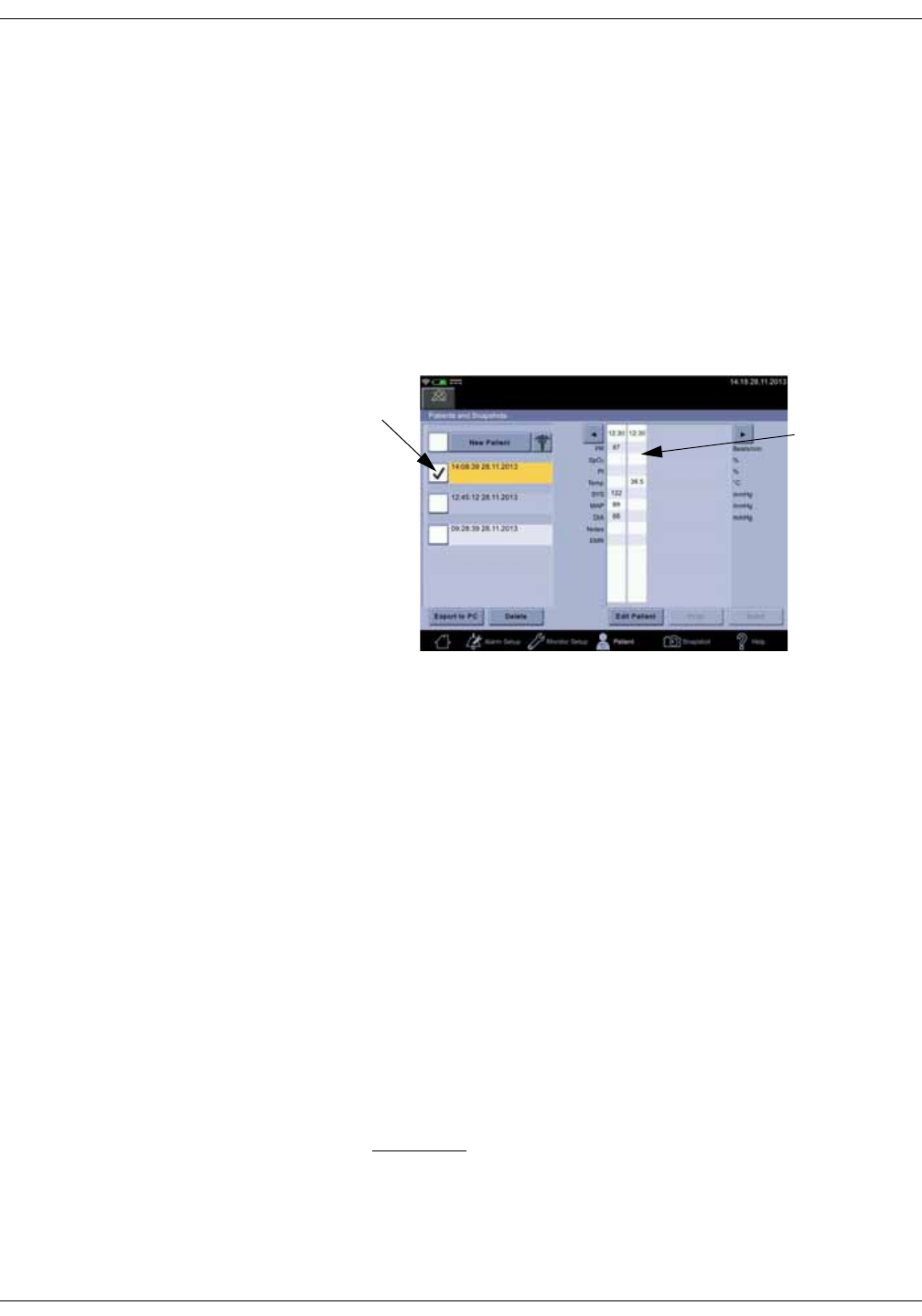
5-2 VC150 Vital Signs Monitor KO00065K
Patient and caregiver data: Description
Description
The Patient screen allows you to access stored patient data. Retrieving
snapshot points is especially useful when doing hospital rounds: if the patient’s
temperature and SpO2 measurements are taken while an NIBP determination is
in progress, then upon completion of the determination, the vital signs for a
patient can be analyzed on screen or printed out.
The following information refers to operation in clinical mode. The monitor can
hold 3000 stored entries in history. It displays the most recent entries first.
Entries are automatically removed when they become older than 24 hours if
these are not printed to a PDF or queued up for sending to the EMR.
The patient data is maintained and displayed in the Patient screen with a time
stamp at the top of the snapshot. Missing parameter data leaves an empty
column in the table. Admitting a new patient also creates an empty column. A
new snapshot is added to the left side of the table.
An entry is stored in local clinical history at the completion of an NIBP
determination and at the completion of an Exergen temperature measurement
or a successful predictive Welch Allyn temperature measurement. At the end of
an NIBP determination, systolic, diastolic, MAP and PR values are stored.
NOTES
When SpO2 is being monitored continuously, values are only stored when
the snapshot icon is selected. Predictive temperature values are stored
separately after each determination. If Snapshot upon NIBP completion
has been selected in configuration mode, then current SpO2 value is stored
when NIBP measurement is complete.
Only those items that are selected to display on the screen are stored in the
snapshot. Visible screen items can be adjusted in the related parameter tab
in Monitor Setup.
CAUTION
If you need to use another unit of measurement for NIBP, first send all
important patient data to the hospital EMR and then ask service to
change the unit of measurement.
Stored entry
field for a
patient
Patient list
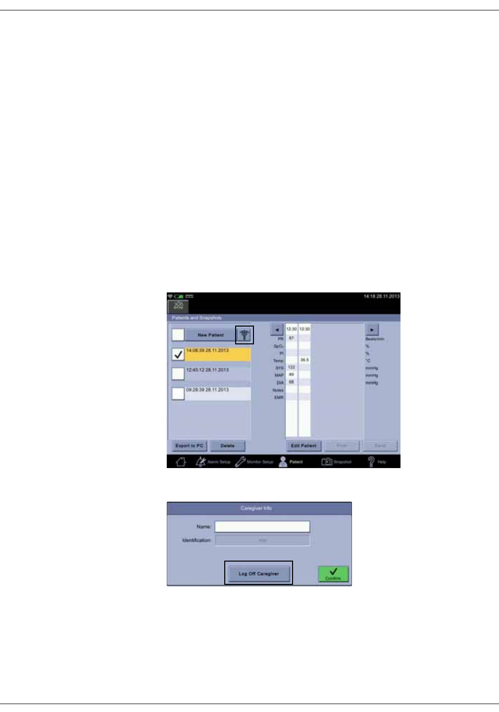
KO00065K VC150 Vital Signs Monitor 5-3
Patient and caregiver data: Adding a caregiver
Adding a caregiver
Depending on hospital policy, the caregiver name might be used although it has
not been identified. If the hospital policy requires validation of the caregiver
identification, it is possible only if a WLAN connection to the hospital network has
been set up and LDAP (Lightweight Directory Access Protocol) is configured
correctly by service personnel.
Depending on country-specific laws of personal identity protection, the hospital
IT system may return different search results. Still, the main purpose of the
search is to confirm the identity of a caregiver or connect a patient to a correct
identity. The following sections explain how to provide identification and positive
caregiver or patient identification. If the caregiver name is not provided, but the
ID has been validated by LDAP, the ID will be displayed as the caregiver.
Providing identification
1. Select caregiver button to access Caregiver Info. If you want to scan ID
barcode, refer to “Using a barcode reader for caregiver ID” on page 5-5.
2. If another caregiver is logged on, select Log Off Caregiver.
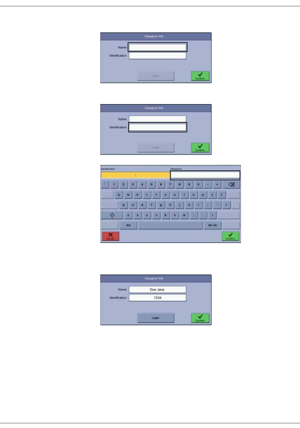
5-4 VC150 Vital Signs Monitor KO00065K
Patient and caregiver data: Adding a caregiver
3. Select Name and enter your name.
4. Select Identification and enter your ID and password.
5. Select Confirm to confirm the entry or Cancel to cancel the selection.
6. Select Login to validate the login credentials.
7. If the ID was validated by the LDAP, the identification turns to gray.
8. If the identification was not validated and this is required by the hospital
policy, re-enter the identification and the password and select Confirm.
9. If a wrong identification was confirmed, select Log off Caregiver to
discharge the previous caregiver and start the caregiver identification
process again.
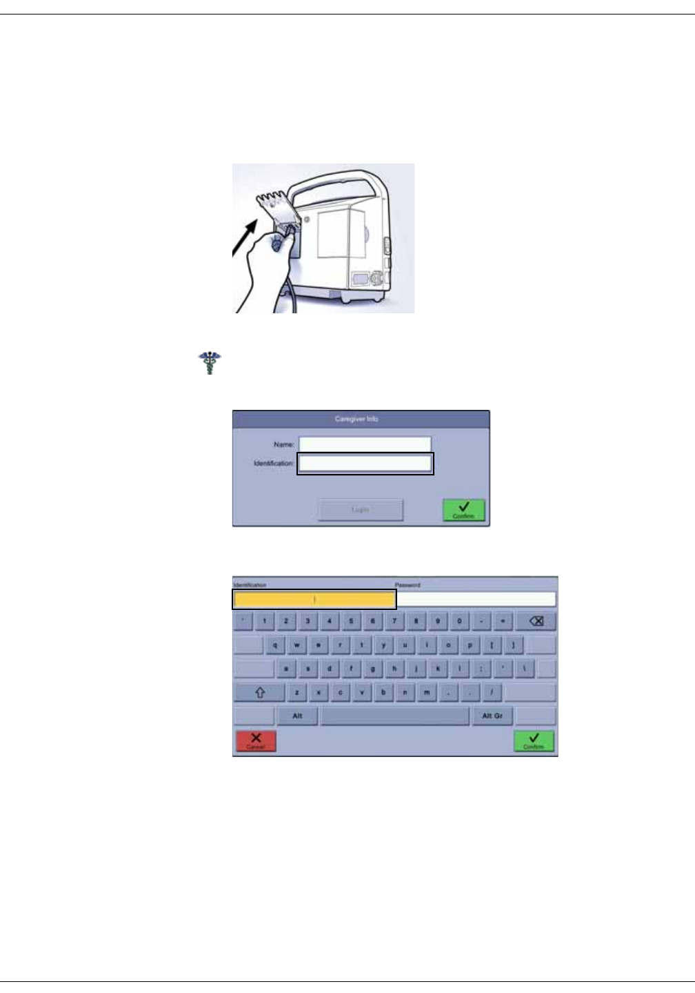
KO00065K VC150 Vital Signs Monitor 5-5
Patient and caregiver data: Adding a caregiver
Using a barcode reader for caregiver ID
Caregiver identity can be verified by scanning the ID badge or entering the
username and then providing a password.
1. Check that a barcode reader is plugged in.
2. Select Patient.
3. Select the caregiver icon.
4. Select Identification.
5. Select Identification.
6. Read the barcode.
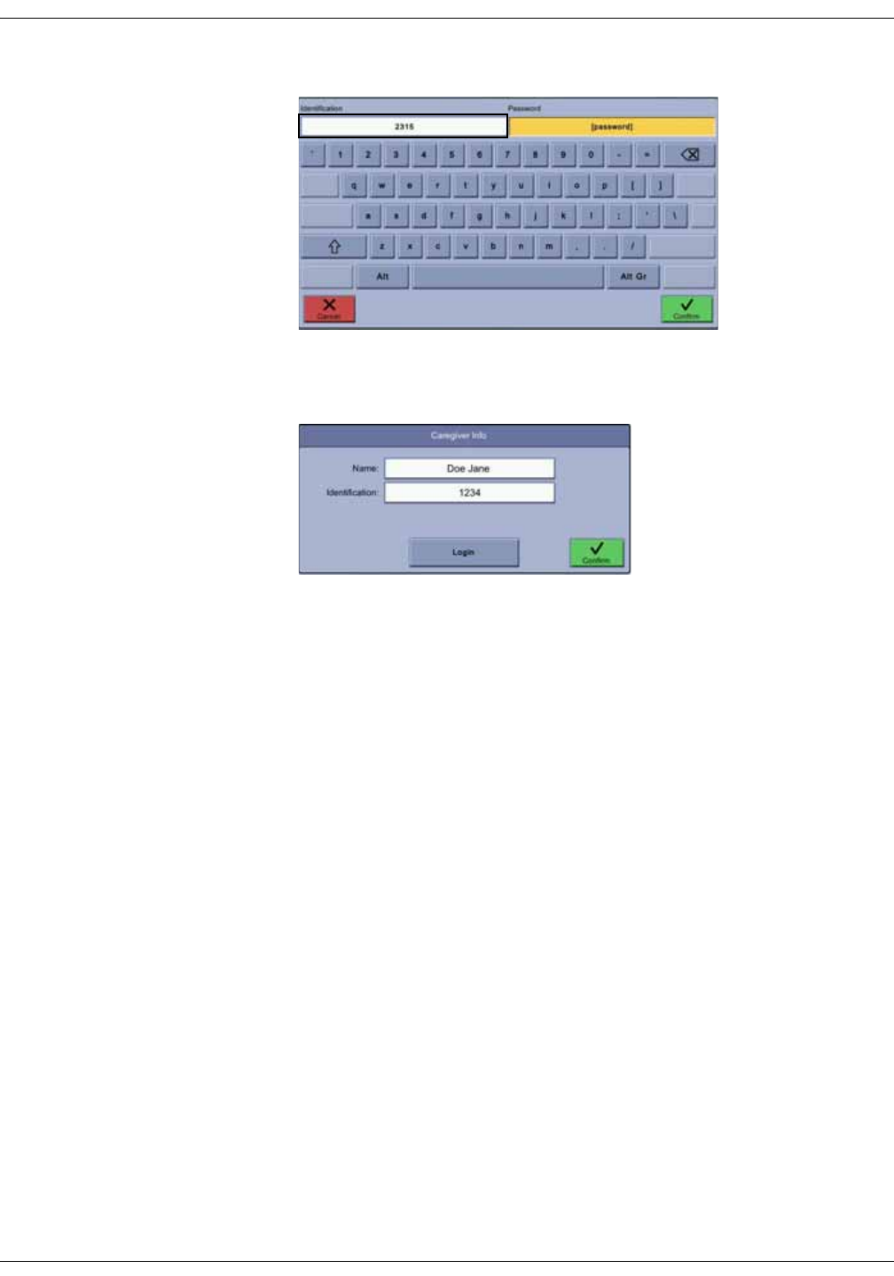
5-6 VC150 Vital Signs Monitor KO00065K
Patient and caregiver data: Selecting or adding a patient
7. Enter your password.
8. Select Confirm to confirm the entry or Cancel to cancel the selection.
9. Select Login to validate the login credentials.
10. If the ID was validated by the hospital LDAP, the identification turns to gray.
11. If the identification was not validated and this is required by the hospital
policy, re-enter the identification and the password and select Confirm.
12. If a wrong identification was confirmed, select Log off Caregiver to
discharge the previous caregiver and start the caregiver identification
process again.
Selecting or adding a patient
The patient ID can be entered manually or scanned with a barcode reader.
Adding a new patient will discharge the current patient.
1. If you want to use a barcode reader to admit a patient, first refer to “Using a
barcode reader for patient ID” on page 5-8, then proceed to step 5 on this
list. Otherwise continue to step 2.
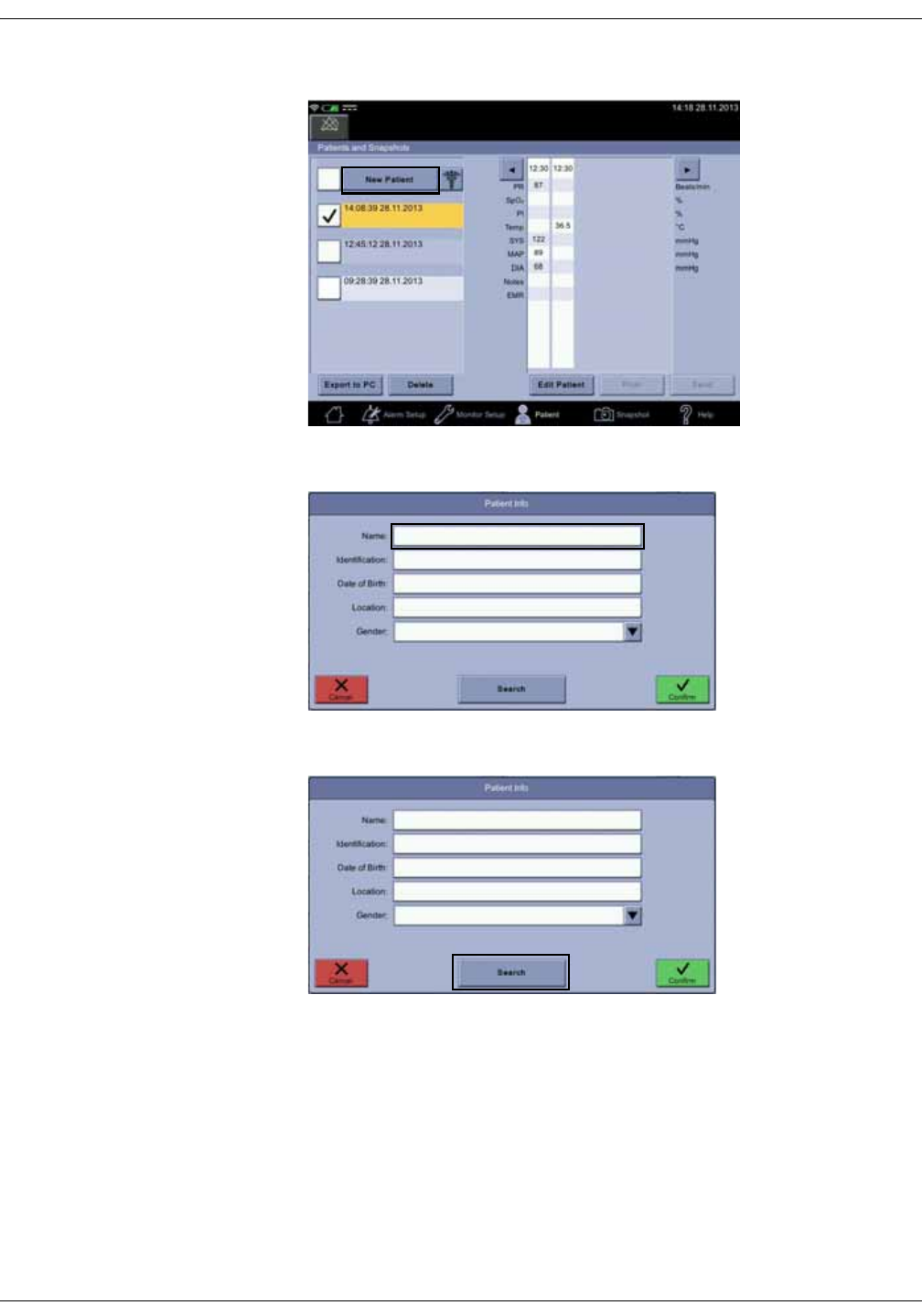
KO00065K VC150 Vital Signs Monitor 5-7
Patient and caregiver data: Selecting or adding a patient
2. Select Patient > New Patient.
3. Select Name.
4. Enter name and then select Search to look for the patient in the HIS.
NOTES
If WLAN and ADT (admission, discharge & transfer)/PDQ (patient
demographics query) are configured correctly by service, the Search icon is
enabled and you can search for the patient in the HIS.
Information fields returned by the HIS (hospital information system) may
vary depending on local laws and hospital policy.
The Search icon is also disabled if the hospital policy requires caregiver
authentication and this has not been done (refer to Providing identification).
You can still enter the patient information and admit a new patient.

5-8 VC150 Vital Signs Monitor KO00065K
Patient and caregiver data: Selecting or adding a patient
5. Proceed to “Positive patient identification” on page 5-9.
Using a barcode reader for patient ID
The patient identity can be provided by scanning the barcode on the patient’s
wristband. The barcode will be automatically read and placed in the patient
Identification field, if service has enabled the Barcode shortcut feature. The
shortcut can be used at any screen, except when text input field or any pop-up is
active.
1. Check that a barcode reader is plugged in.
2. Scan the barcode on the patient’s wrist band with the barcode reader while
the monitor is e,g, on the home screen. After scanning, the monitor will
launch the Patient info screen and fill in the patient ID into required field.
3. Proceed to step 5 of “Selecting or adding a patient” on page 5-6.
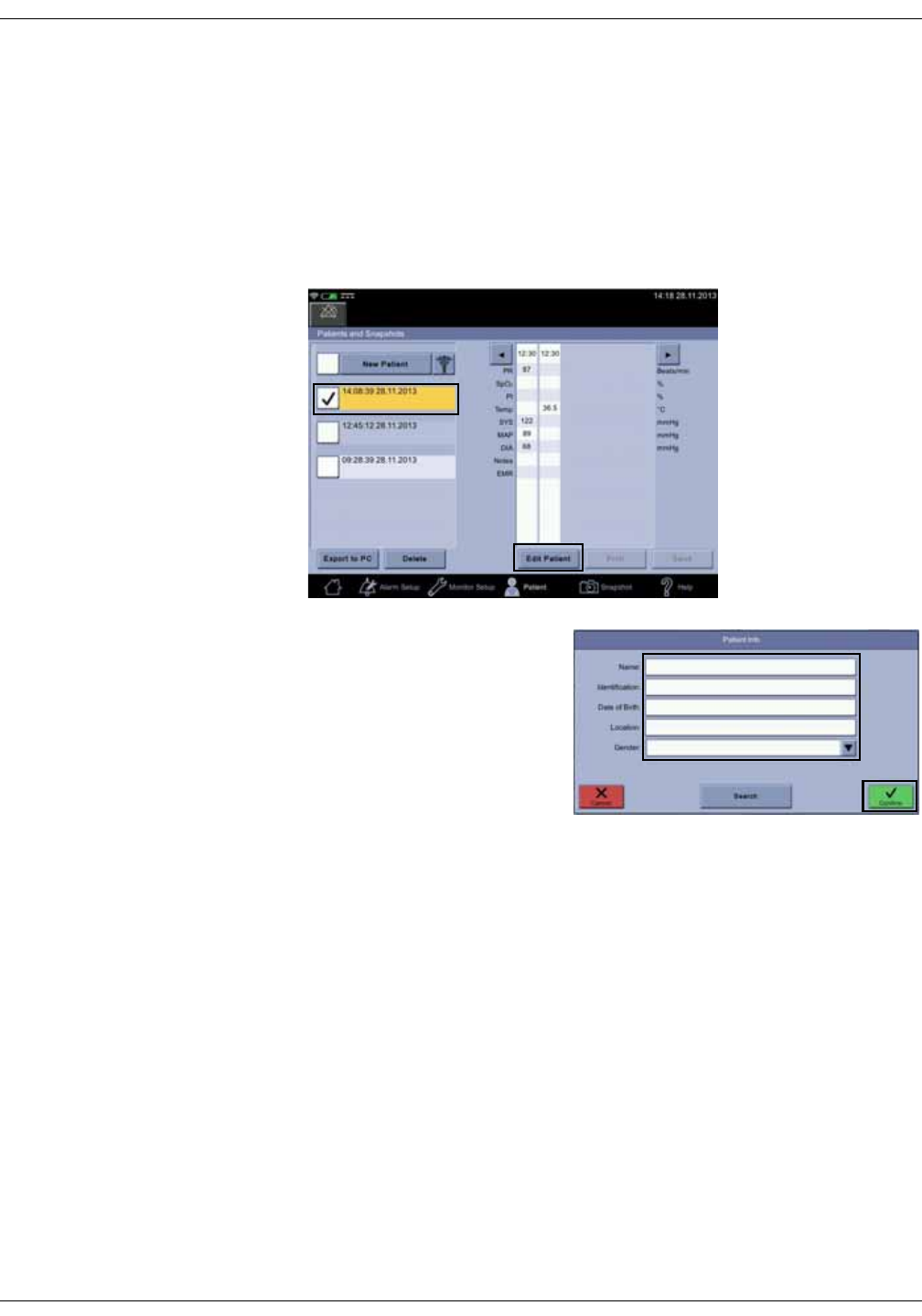
KO00065K VC150 Vital Signs Monitor 5-9
Patient and caregiver data: Selecting or adding a patient
Positive patient identification
1. When the search returns a name, ask the patient for his/her name or date of
birth. If the information about the new patient matches what the patient has
said, select Confirm.
2. If the search returned a wrong name, select Cancel and proceed to
“Selecting or adding a patient” on page 5-6.
3. If a wrong patient was confirmed, select Edit patient.
4. Edit patient data and select
Confirm.

5-10 VC150 Vital Signs Monitor KO00065K
Patient and caregiver data: Snapshots
Snapshots
Obtaining vital signs snapshots for a patient
1. Perform measurements on a patient as instructed for each measurement.
2. Some snapshots are created automatically for measurements that have a
clear end point. For measurements in process, select Snapshot to create a
snapshot. All data is stored in a snapshot if Snapshot upon NIBP
completion is enabled in configuration mode and temperature is in monitor
mode.
Measurement Source Capture
NIBP NIBP Automatic
Temperature Welch Allyn Automatic
(when predictive mode is used)
Manual
(when monitor mode is used, animated
snail icon on screen)
Exergen Automatic
Pulse NIBP
SpO2Manual
or
Automatic
(if enabled in Snapshot upon NIBP
completion)
SpO2GE TruSignal
PI SpO2
SpO2Nellcor
Respiration
SpO2Masimo
Respiration
SpMet
SpCO
SpHb
SpOC
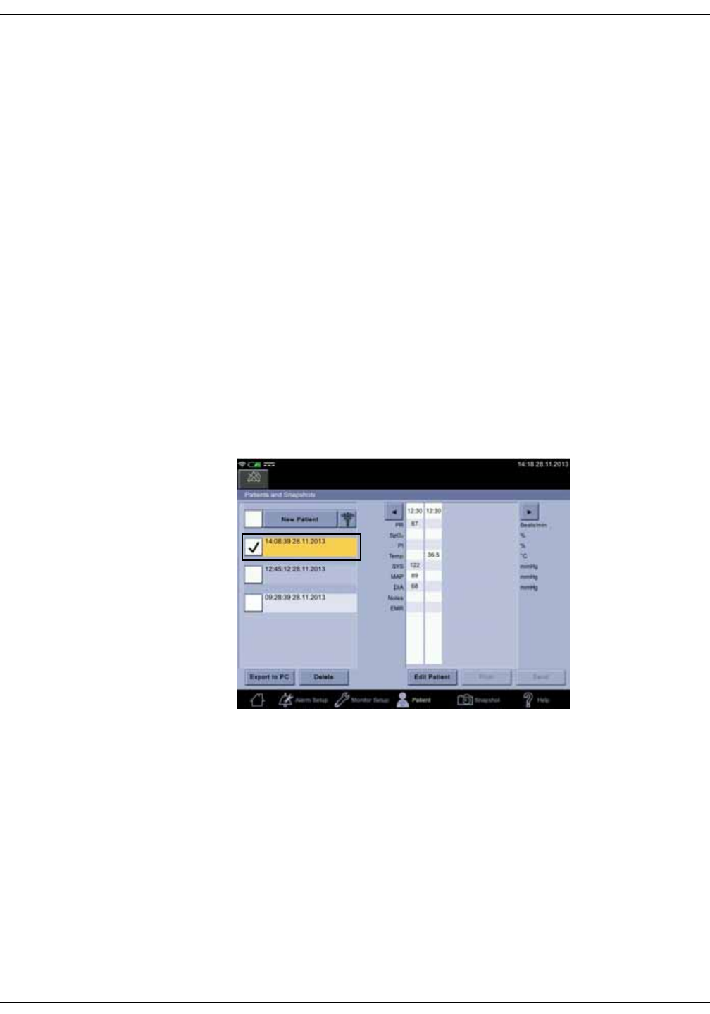
KO00065K VC150 Vital Signs Monitor 5-11
Patient and caregiver data: Snapshots
NOTES
If the Snapshot icon was selected before any SpO2 monitoring data was
available, SpO2 and pulse rate cells will be empty. The cells will also be
empty if there is no measurement data available.
If a patient is being measured for over an hour, the patient data will be split
into one-hour intervals. This also happens if the number of snapshots
exceed 50. Different patients are separated by name.
You can scroll the snapshots back and forth with left and right arrows next
to the snapshot list. The page count displays the current set of snapshots.
3. If you want to add notes on the patient’s condition, refer to “Notes” on
page 5-12.
4. Repeat measurements if more snapshots are required.
5. When examination is complete, remove the cuff and sensor.
Viewing snapshots
1. Select Patient.
2. Select the patient whose snapshots you want to view. The selected patient
will turn orange.
3. Select a snapshot you want to view. Scroll to the snapshot with arrows or
with the scroll bar.
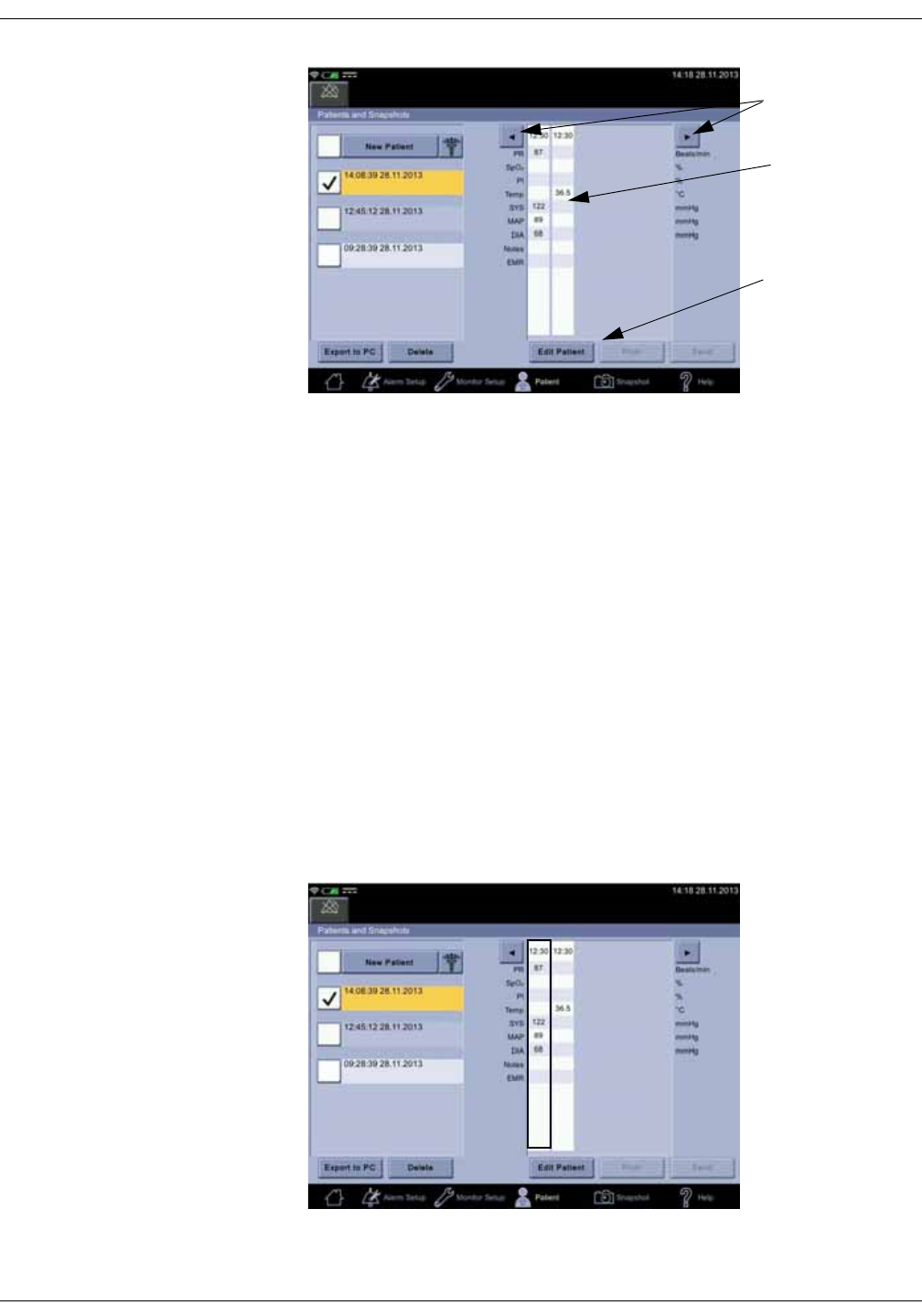
5-12 VC150 Vital Signs Monitor KO00065K
Patient and caregiver data: Snapshots
NOTE
If recent snapshots were taken without patient identification:
1. Select New Patient. Add patient as instructed in “Selecting or adding
a patient” on page 5-6.
2. Select Confirm to return to the snapshot screen. Now the snapshots
are assigned to the newly identified patient.
Notes
You can add additional information about the patient’s condition, such as Pain
Score, Respiration Rate, Consciousness, Input and Output. In addition to these,
service can customize five additional fields for notes.
Adding notes
1. Select Patient.
2. Select a snapshot to which you want to add a note.
A snapshot with
stored entries for
a patient
Scroll bar
Scroll arrows
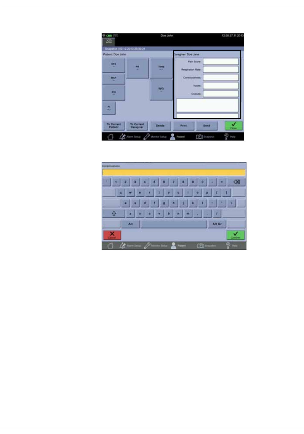
KO00065K VC150 Vital Signs Monitor 5-13
Patient and caregiver data: Snapshots
3. Select a note to which you want to add text.
4. Enter the information.
5. Select Confirm.
6. Repeat steps 2 to 4 to add more notes.
7. When you are ready with the notes, select:
•To Current Patient to assign the snapshot to a current patient.
•To Current Caregiver to assign the snapshot to a current patient.
•Delete to delete the snapshot.
•Print to print the snapshot with the monitor strip printer.
•Send to send the notes to the hospital EMR via wireless connection. Send is
available only if a WLAN connection and EMR are configured.
•Close to return to the Patients and Snapshots screen.
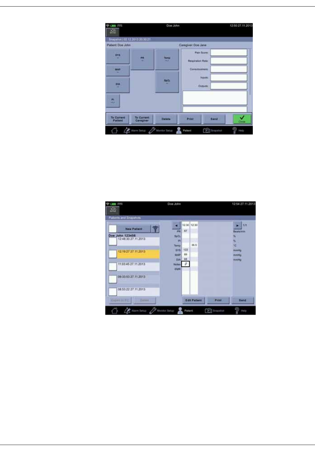
5-14 VC150 Vital Signs Monitor KO00065K
Patient and caregiver data: Snapshots
NOTES
Export to PC, Delete, Print and Send buttons are disabled if the selected
patient does not have any snapshots.
If you sent the snapshot with the notes, then select Close. A pencil image at the
intersection of the snapshot column and Notes row indicates there is something
in the Notes area.
NOTE
Service can configure the monitor to delete a snapshot after records have
been sent out.
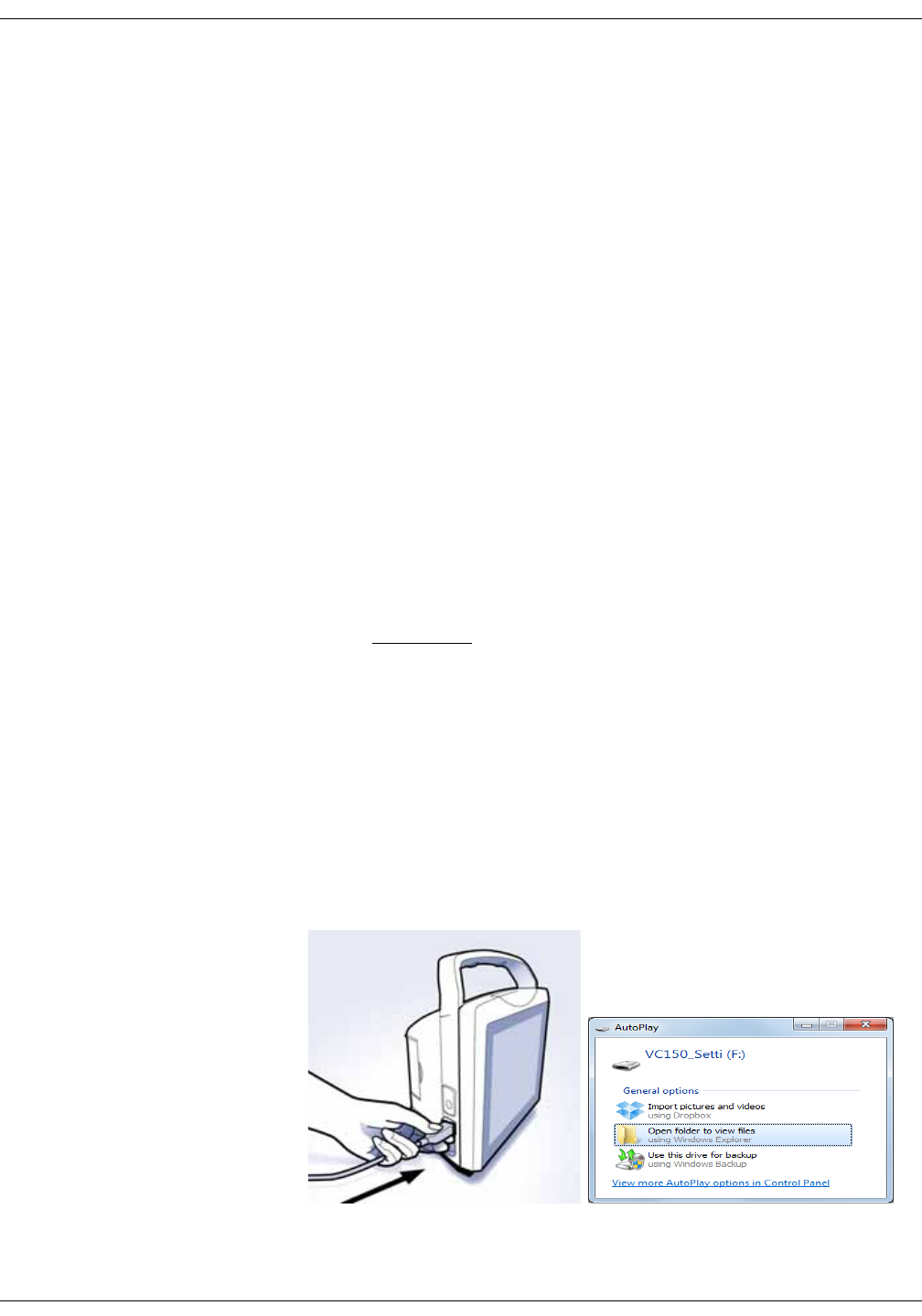
KO00065K VC150 Vital Signs Monitor 5-15
Patient and caregiver data: Snapshots
Snapshot output
All or selected patient data can be printed, saved to a PDF, exported to USB as a
PDF or transferred to the hospital EMR.
1. Select the patient as instructed in “Selecting or adding a patient” on page 5-
6.
2. Select the patient interval.
3. Select the output type. Read further instructions below before you make a
selection.
•Export to PC. A PDF file for the selected interval is created and sent to a PC
through USB. Service can set the PDF paper size as A4 or Letter.
•Delete. The selected interval is deleted.
•Edit Patient. Patient and caregiver information can be edited.
•Print. The selected patient intervals are sent to the monitor printer.
•Send. The selected intervals are sent to the hospital EMR if the patient has
been identified. Also, the WLAN connection must be set up and the EMR
destination configured by service. Name of the responsible caregiver is
marked in all sent snapshots.
Export to PDF
WARNING
Electromagnetic interference from a desktop or a laptop computer
connected to the VC150 may affect the performance of the monitor. Do
not use the monitor for vital signs measurements while connected to a
PC or laptop via USB-B connection.
1. Plug in a USB-B cable to a USB-B slot on the left side of the monitor and to
the USB-A slot on a PC or Macintosh. The monitor looks like an external
device on the file management system of the PC or Macintosh.
NOTE
The operating system of the PC or Macintosh must be new enough to
support USB plug and play.
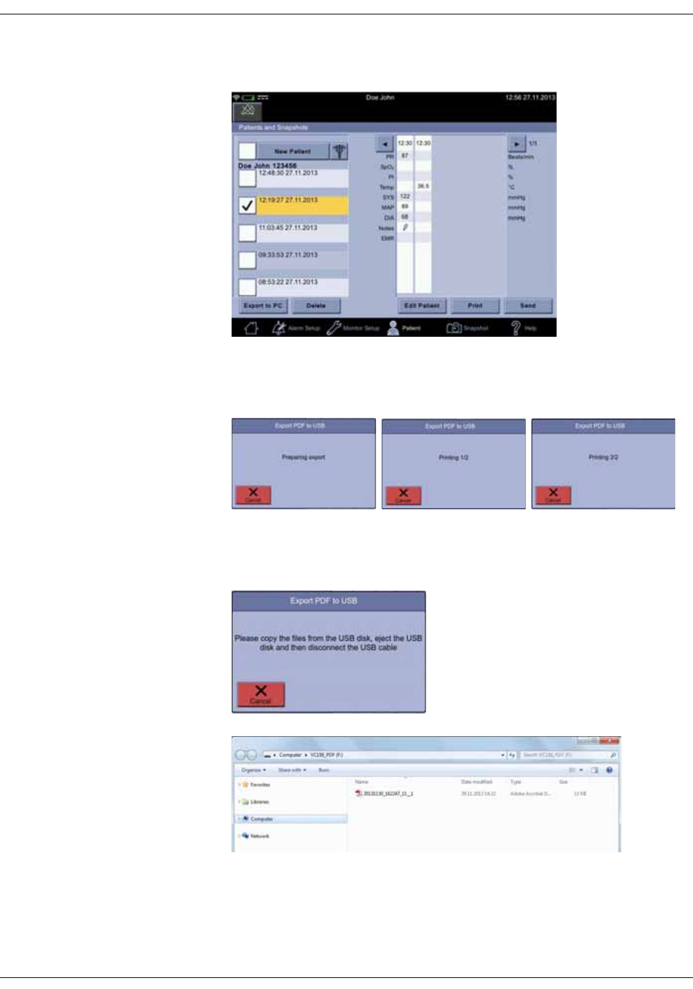
5-16 VC150 Vital Signs Monitor KO00065K
Patient and caregiver data: Snapshots
2. Select a patient interval. The monitor will mark snapshots with all available
values in the selected interval of the patient data.
3. Select Export to PC. The monitor starts to a create a PDF out of marked
snapshots. Do not print more than 1000 snapshots for a selected period.
Save the PDF to a PC before printing more snapshots than that.
4. When the monitor has completed creation of the PDF files, you will see a
following note on the screen. The PDF files can now be copied from the root
directory onto the PC or MAC.
5. When you have copied the files, export more files or eject the USB device.
6. Unplug the USB.
7. Confirm the file export to exit the screen.
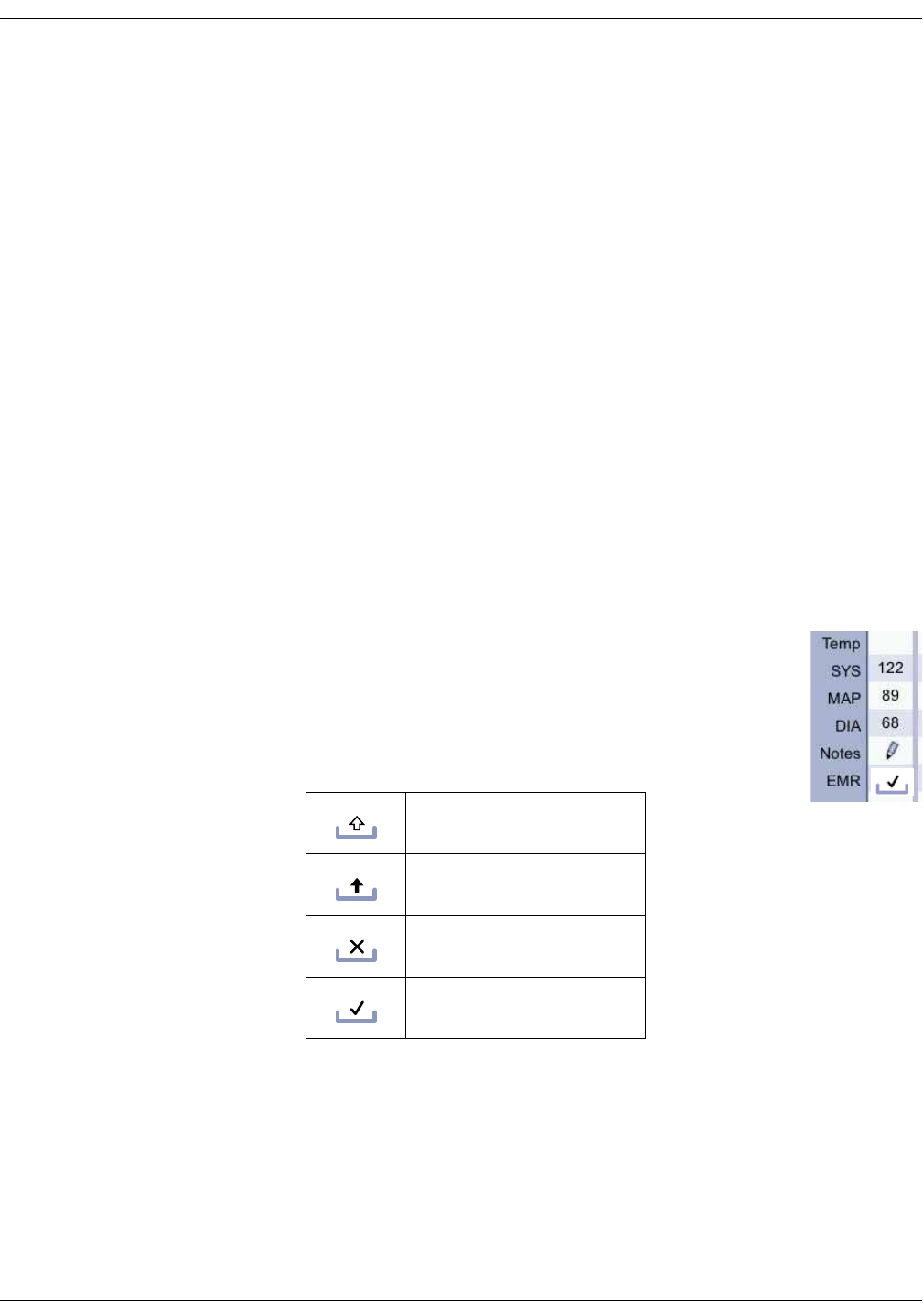
KO00065K VC150 Vital Signs Monitor 5-17
Patient and caregiver data: Snapshots
Print
Printed content vary depending on which SpO2 and temperature technology is
used to provide the data. A time stamp will be printed at the top of each
snapshot. Column cells of a snapshot may be empty if values are not available
or invalid. To tear off the printout, use a slight sideways action to pull the paper
sharply up across the edge of the door.
Send
If the wireless network connection has been set up and the vital signs
measurements for the case in question are associated with a patient identity,
the Send icon is active. If the transfer was successful and deletion of sent
records is enabled, the transferred snapshots will be removed from the screen. If
the transfer was unsuccessful, then snapshots will turn gray and a gray
technical message about a missing connection is displayed. The monitor will
send the gray snapshots when the transfer becomes possible again.
NOTE
If you delete the patient, the monitor will ask for confirmation and checks
also whether you want to delete also the unsent data. Deleting the current
patient will discharge the patient.
Automatic snapshot deletion
By default, the monitor automatically deletes snapshot(s) after
successfully transfer to the EMR. If you want to disable this, ask
service to change the setting. An icon on snapshot cell indicates
the status of the sending process of the snapshot. If Delete Sent
Records has been enabled by service, the selected snapshot will
disappear from the screen after successful transfer to the EMR.
Preparing to send
Sending
Sending failed
EMR sent to the HIS
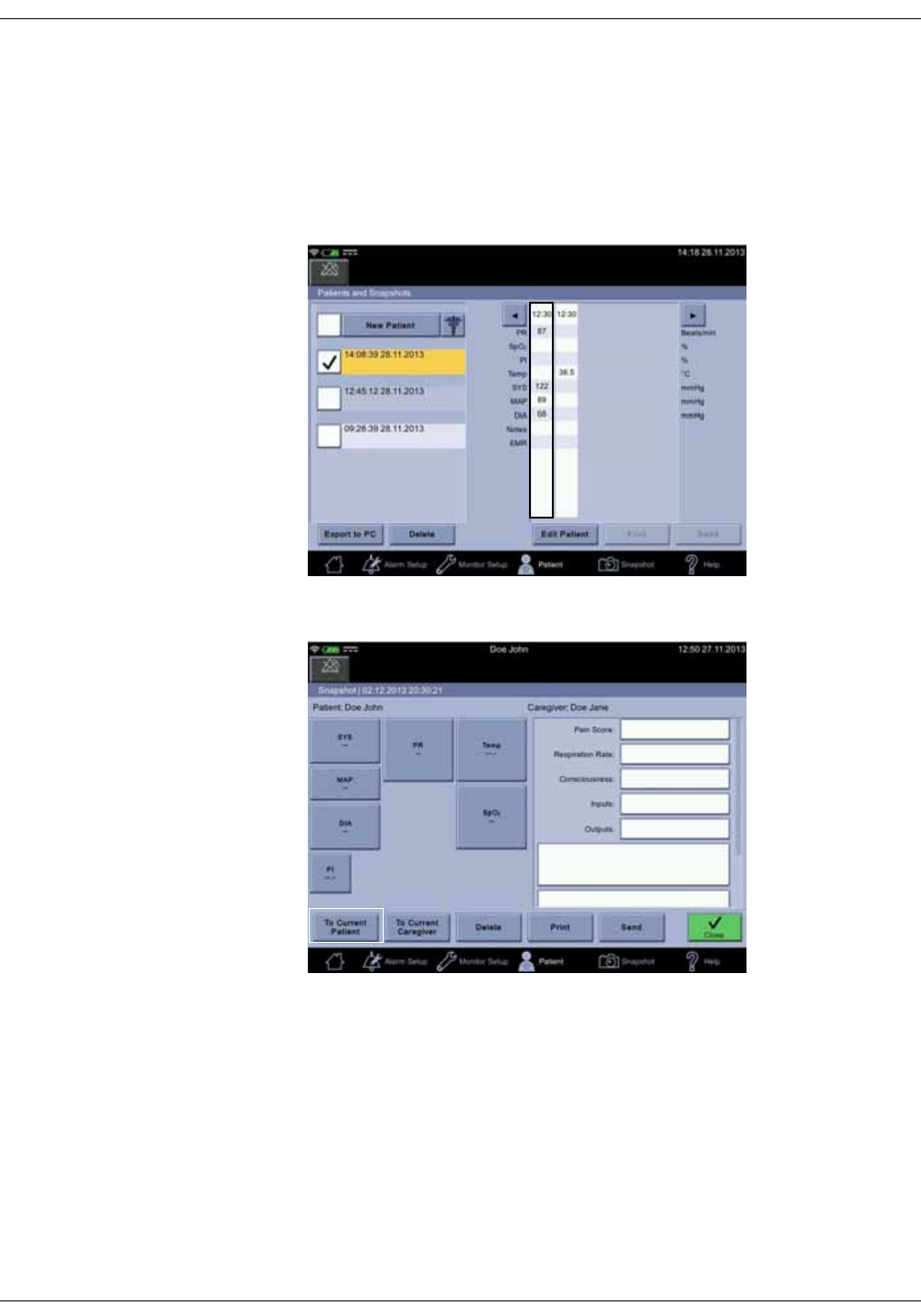
5-18 VC150 Vital Signs Monitor KO00065K
Patient and caregiver data: Snapshots
Assigning snapshots to a patient
1. Select Patient.
2. Select a patient as instructed in “Selecting or adding a patient” on page 5-6.
Then select Confirm to return to the snapshot screen.
3. Select a snapshot.
4. Select To Current Patient.
5. Select Close.
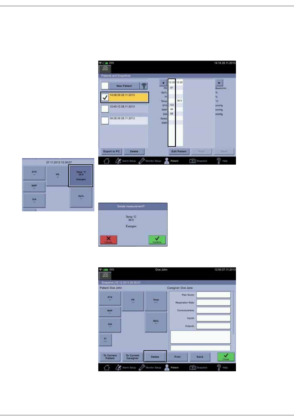
5-20 VC150 Vital Signs Monitor KO00065K
Patient and caregiver data: Snapshots
Deleting snapshot and notes
1. Select a patient as instructed in “Selecting or adding a patient” on page 5-6.
2. Select a snapshot.
3. If you want to delete a single measurements within a snapshot, select the
measurement.
4. Select Confirm to delete the measurement or Cancel to exit the screen.
5. If you want to delete the snapshot with all measurements, select Delete.
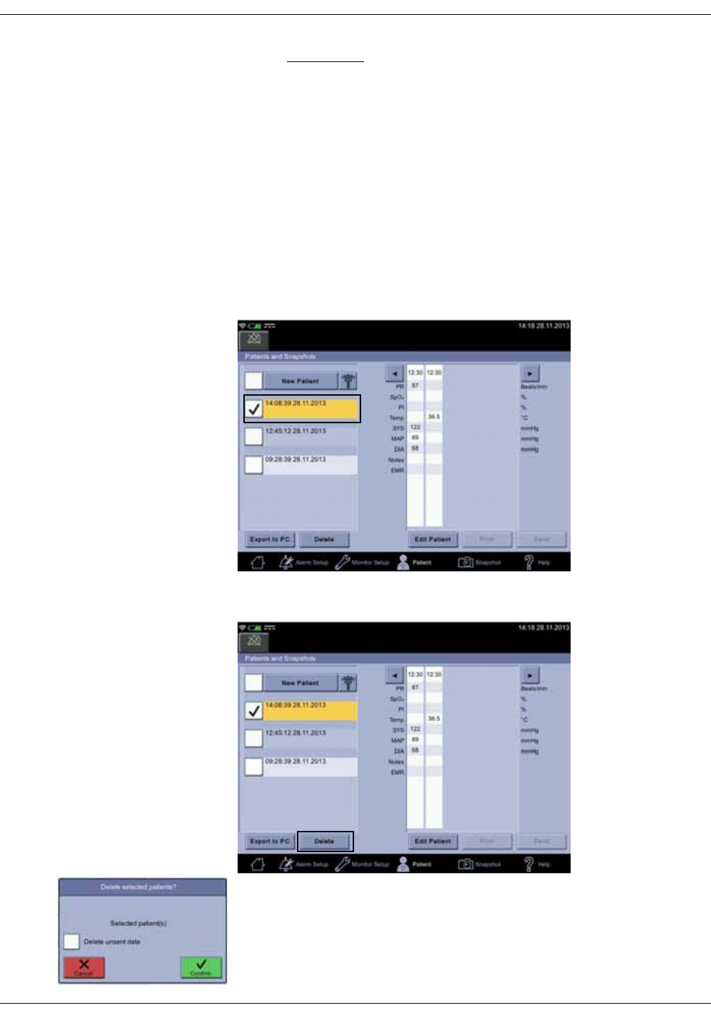
KO00065K VC150 Vital Signs Monitor 5-21
Patient and caregiver data: Snapshots
WARNING
Make sure the selection(s) is/are correct before deleting. The action will
take place immediately after selecting the drop-down list item. There is
no way to restore entries that have been erroneously deleted.
6. Select Close to return to the Patient and Snapshots screen.
Deleting patient history
Deleting patient history is possible only if there no pending transmissions to the
EMR. If there is an absolute need to delete local history, contact service.
1. Select the Patient screen.
2. Select a patient in the patient history list.
3. Select Delete.
4. Confirm the deletion with Confirm or cancel the deletion with Cancel.

5-22 VC150 Vital Signs Monitor KO00065K
Patient and caregiver data: Troubleshooting
WARNING
Make sure the selection is correct before selecting Confirm. The action
will take place immediately after confirmation. There is no way to
restore patient entries that have been erroneously deleted.
Troubleshooting
The printer does not print
The printer may be unavailable if:
• The user has exited the Patient screen before the print command was sent
to the printer.
• The battery is nearly depleted. No printouts of any type will print.
• The monitor is too hot.
• The paper is out.
• The printer option was not ordered.
Transmission to the EMR is unavailable
If the problem persists, contact service to set up wireless and/or EMR
connection.
Patient search is unavailable
Contact service to set up wireless and/or EMR connection.
Forgotten password or ID
Contact hospital IT to reset the password or provide the ID.
Barcode reader does not work
Unplug and reconnect the barcode scanner. If the problem persists, contact
service.
Red light in barcode reader
There is not sufficient power for barcode reader. Contact service.

KO00065K VC150 Vital Signs Monitor 6-1
6NIBP

6-2 VC150 Vital Signs Monitor KO00065K
NIBP: Description
Description
The NIBP parameter in the monitor is available with two types of NIBP
technologies: one calibrated to intra-arterial pressure (DINAMAPTM SuperSTAT)
and one calibrated to the auscultatory method.
The type of NIBP technology used by the monitor is indicated in the Monitor
Setup > NIBP screen. Refer to “NIBP settings” on page 6-12.
Refer to “Principles of noninvasive blood pressure determination (NIBP)” on
page C-1 for a description of the principles of operation of NIBP. User interface
options, instructions for use, and alarms are the same for all technologies. The
NIBP parameter is included in all models. Blood pressure is measured
noninvasively in the monitor by oscillometric method.
NOTE
For neonatal populations, the reference is always the intra-arterial pressure
monitoring method. The monitor automatically switches from Auscultatory
to SuperSTAT whenever a neonatal cuff is detected.
The monitor has four NIBP modes: 1. Single determination, 2. STAT, 3. Cycle, 4.
Profile cycle. The mode is selected by the user. The actual NIBP determination is
automated and once it is complete, the values for systolic pressure, diastolic
pressure, mean arterial pressure, and pulse rate (if SpO2 is not active) are shown
in their respective windows.
Before each NIBP determination, the monitor ensures the cuff has been deflated
from the previous determination. The determination is delayed until this
condition is met. The monitor senses the type of hose being used and
automatically uses adult/pediatric monitoring parameters or neonate
monitoring parameters as appropriate.
NOTES
Audible and visible alarms occur in monitoring mode when any of the values
for systolic pressure, diastolic pressure, or pulse rate (if sourced by NIBP) are
outside their selected high or low limits. Alarms are disabled in spot-check
mode.
If the internal battery is depleted during NIBP determination, the cuff will
deflate automatically.
When the Battery Low (5 minutes left) alarm is signaled, NIBP is disabled
and the monitor will automatically shut down in 5 minutes. Connect the
power cable to continue using the monitor.
CAUTION
The RADIAL-CUF has been validated for use only with GE SuperSTAT
algorithm for adult obese patients. The RADIAL-CUF has not been
validated for use against the GE Auscultatory algorithm. Refer to the
RADIAL-CUF instructions for use for sensor requirements.

KO00065K VC150 Vital Signs Monitor 6-3
NIBP: Description
Differences in intra-arterial and auscultatory references
Intra-arterial reference
The intra-arterial reference algorithm was developed based on blood pressure
values obtained with an intra-arterial catheter (e.g., central aortic). The accuracy
of the DINAMAPTM SuperSTAT algorithm has been demonstrated through a
clinical study to meet or exceed AAMI SP10 requirements where the reference
measurements were made from an intra-arterial catheter placed in the
ascending aorta.
Auscultatory reference
The auscultatory reference algorithm was developed based on noninvasive
blood pressure values obtained with a sphygmomanometer, a stethoscope, and
listening to the Korotkoff sounds. The accuracy of the auscultatory algorithm
has been shown to achieve an overall A/A grade using the BHS study protocol
where reference measurements are made through auscultation with
sphygmomanometers.
DANGER
Connect cuffs and inflation systems only to systems designed for
noninvasive blood pressure monitoring. Devices with luers and locking
luer connectors may be inadvertently connected to intravascular fluid
systems that may allow air to be pumped into a blood vessel.
WARNINGS
The blood pressure measurement may not be accurate with patients
who are experiencing seizures or tremors.
Carefully route the external AC/DC power converter, air hoses, and all
cables to reduce the possibility of entanglement or strangulation.
Arrhythmias will increase the time required by the NIBP parameter to
determine a blood pressure and the monitor may not be able to
complete a measurement on patients of this type because of the safety
time limit (maximum allowed time for the parameter: 120 seconds for
adult/pediatric and 85 seconds for neonatal).
In spot-check mode, the monitor displays the results of the last blood
pressure determination. The measurement data is automatically stored
in patient data. If the monitor remains in spot-check mode and a
patient's condition changes between one determination and the next,
the monitor will not detect the change or indicate an alarm condition.
It is possible to set the alarm limits for pulse rate outside of the
operating range for the NIBP parameter. Under such conditions, an
alarm will not occur.

6-4 VC150 Vital Signs Monitor KO00065K
NIBP: Description
CAUTIONS
Do not use an infant cuff with an auscultatory reference. The neonatal
#5 cuff and neonatal hose may be used on patients with an arm
circumference of 8 - 15 cm.
Blood pressure cuffs should be removed from the patient when the
monitor is not in use. If the extremity remains cuffed under these
conditions or if the interval between blood pressure determinations is
prolonged, the patient’s limb should be observed frequently and the cuff
placement site should be rotated as needed.
The pulse rate derived from an NIBP determination may differ from the
heart rate derived from an ECG waveform because the measurement
derived from NIBP measures peripheral pulses, not electrical signals or
contractions from the heart. Differences may occur because electrical
signals at the heart occasionally fail to produce a peripheral pulse or
the patient may have poor peripheral perfusion. Also, if a patient’s beat-
to-beat pulse amplitude varies significantly (e.g., because of pulsus
alternans, atrial fibrillation, or the use of a rapid-cycling artificial
ventilator), blood pressure and pulse rate readings can be erratic, and
an alternate measurement method should be used for confirmation.
Several conditions may cause the NIBP parameter to calculate and
display only the mean arterial pressure without systolic and diastolic
readings. These conditions include very low systolic and amplitude
fluctuations, so an accurate calculation for these values can’t be made
(e.g., patient in shock); too small of a difference between systolic and
MAP calculations in relationship to the difference between diastolic and
MAP; or a leak has occurred in the cuff or connector outside the monitor.
Avoid contact with the cuff while monitoring, since it may cause
inaccurate blood pressure values.
Devices that exert pressure on tissue have been associated with
purpura, skin avulsion, compartment syndrome, ischemia, neuropathy
and/or thrombosis. To minimize these potential problems, especially
when monitoring at frequent intervals or over extended periods of time,
make sure the cuff is applied appropriately and examine the cuff site
and the limb distal to the cuff regularly for signs of impeded blood flow.
NOTES
The monitor is designed for use only with GE BP dual-tube cuffs.
Use only GE blood pressure cuffs. The size, shape, and bladder
characteristics can affect the performance of the instrument. Inaccurate
readings may occur unless GE blood pressure cuffs are used.
A patient’s vital signs may vary dramatically during the use of
cardiovascular agents such as those that raise or lower blood pressure or
those that increase or decrease heart rate.
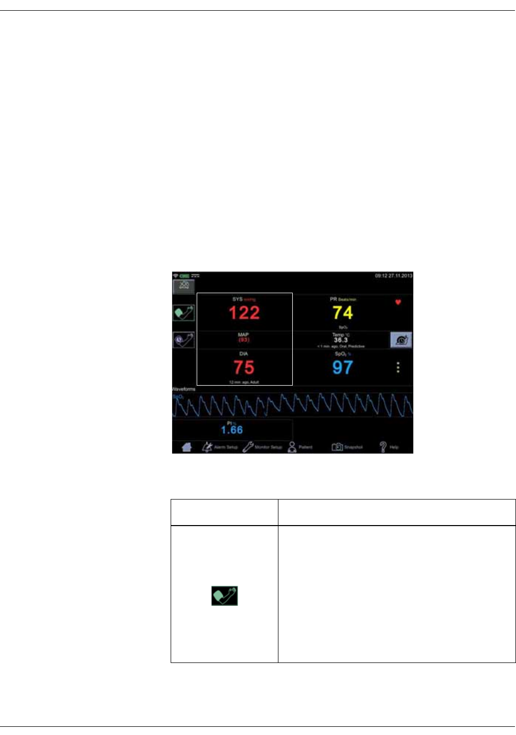
KO00065K VC150 Vital Signs Monitor 6-5
NIBP: NIBP on the monitor screen
Oscillometric method
The oscillometric method of determining NIBP is accomplished by a transducer
that measures small variations in cuff pressure resulting from the pulsatile flow
of blood in the patient's artery while the air pressure in the cuff is varied. These
signals are analyzed by the algorithm resulting in systolic, MAP, and diastolic
pressure estimates calculated to correspond to either an intra-arterial or
auscultatory reference.
NIBP on the monitor screen
The NIBP parameter field is located on the left side of the monitor screen. Blood
pressure-related titles and pulse rate are displayed in red by default. The color of
the unit of measurement and measurement data can be changed in
configuration mode. The NIBP parameter field view varies depending on which
NIBP mode is used and which part of the body is selected for the measurement.
Screen item Description
The start icon starts the NIBP determination process
by first inflating the cuff to the target pressure.
Selecting the terminating icon/red inflate icon
terminates the inflation and the NIBP process
altogether. The NIBP mode icon above the start icon
indicates the chosen NIBP measurement mode.
If a measurement is in progress and the cuff fills with
air, the current pressure is displayed in digits above
the start icon.
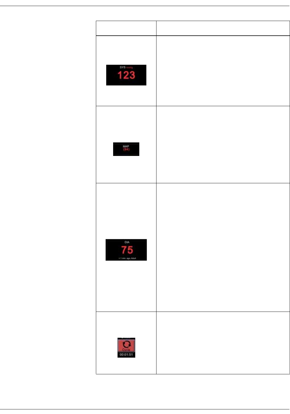
6-6 VC150 Vital Signs Monitor KO00065K
NIBP: NIBP on the monitor screen
SYS
The SYS value displays the label SYS mmHg, which
stands for:
•SYS = systolic blood pressure.
•mmHg = unit of measurement.
Service can change the unit of measurement to kPa
if desired. Limits for SYS can be configured in the
Alarm Setup to trigger an alarm if the SYS value
does not remain within limits.
MAP
The MAP (mean arterial pressure) value is displayed
between the SYS and DIA values. When an NIBP
determination results in MAP only values, the SYS
and DIA fields show dashes instead of numeric
values.
The factory default setting for MAP value limits is
OFF. If enabled, limits can be configured in Alarm
Setup to trigger an alarm if the MAP value does not
remain within user set limits.
DIA
DIA stands for diastolic blood pressure. Limits for
DIA can be configured in Alarm Setup to trigger an
alarm if the DIA value does not remain within limits.
The line below the diastolic value displays the text 1
min ago, Adult, Left, which stands for:
•1 min ago = Time lapsed from the last
measurement.
•Adult = Cuff type recognized by the monitor. If
the cuff is changed, the monitor will recognize
the new cuff during the initial inflation period of
the next NIBP determination. If the monitor
detects a neonatal cuff, the default target
pressure for neonates is used.
•Upper left arm = Cuff position during the last
measurement. Cuff position can be changed in
the Monitor Setup > NIBP screen.
Auto Mode
If a STAT, Cycle or Profile NIBP measurement cycle
has been selected, countdown numbers below the
NIBP mode icon indicate time left before the next
NIBP measurement.
NOTE
The auto mode option can be selected also in
the Monitor Setup > NIBP tab.
Screen item Description
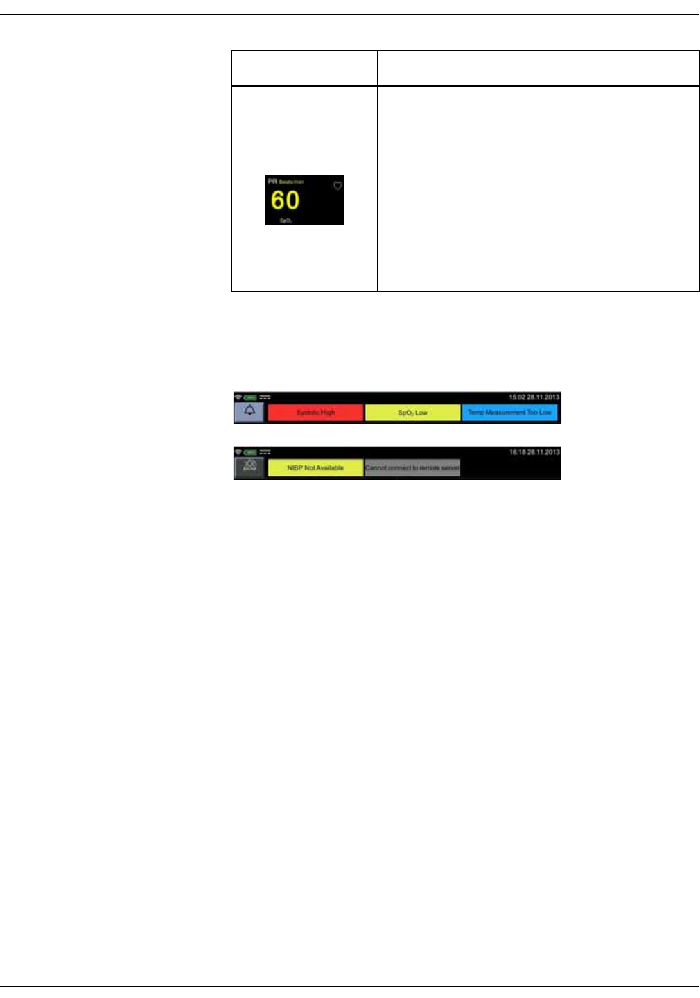
KO00065K VC150 Vital Signs Monitor 6-7
NIBP: NIBP on the monitor screen
Alarms associated with NIBP
Physiological and technical alarms are categorized by priority level:
When an NIBP measurement invokes an alarm:
• The monitor will sound an audible alarm signal.
• An LED light will illuminate at the top of the monitor.
• A message will be displayed in the alarm area of the monitor screen.
• The NIBP value exceeding its limit will be highlighted on screen.
NOTE
Technical error conditions related to NIBP are first displayed under the DIA
value and after 10 seconds as a low priority alarm.
To respond quickly to an alarm, select the silence icon in upper left corner of the
screen. Once this icon is selected, the audible alarm will remain silent for two
minutes. The alarm will reactivate if the monitor continues to receive NIBP
measurement information. To acknowledge an alarm, select the alarm message
on the notification area.
PR
PR is the SpO2 derived pulse rate. If SpO2 is not being
measured or available, PR is the NIBP derived pulse
rate. The pulse rate label consists of the name and
the unit of measure used. A heart symbol is
displayed next to PR. This symbol blinks and an
audio sound is signaled if SpO2 is active and a pulse
is detected.
Limits for PR can be configured in Alarm Setup to
trigger an alarm if the PR value does not remain
within limits.
Screen item Description
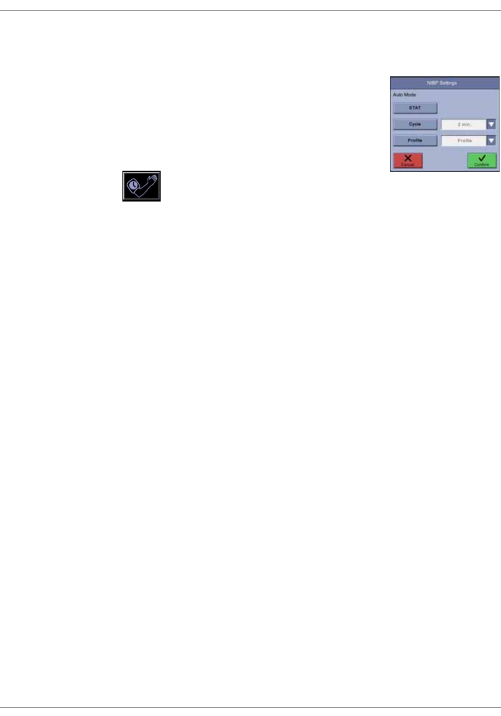
6-8 VC150 Vital Signs Monitor KO00065K
NIBP: NIBP modes of operation
NIBP modes of operation
The monitor has several NIBP modes that can be
selected by the user. NIBP determinations are
automated and, upon completion, the values for
systolic pressure, diastolic pressure, mean arterial
pressure, and pulse rate (if SpO2 is not active) are
shown in their respective windows. NIBP can be
measured once or have as many measurements as
possible within a given time frame using STAT, Cycle
or Profile. NIBP auto mode can be selected in
Monitor Setup > NIBP or selecting the auto mode icon on the screen and then
making the selection.
Profile mode can be configured in password-protected Default Setup. The
Profile settings allow the user control over the sequence of these
determinations. The user may establish multiple groups of NIBP determination
cycle sequences, each with a defined number of NIBP intervals with a defined
duration. When that sequence expires, the next sequence takes over until all
sequences have completed. As an example; one Profile could comprise of 4
determinations at 5-minute intervals followed by 8 determinations at 60-minute
intervals, resulting in a total of 12 determinations over a period of 8 hours and 15
minutes.
NOTES
If an alarm condition emerges and the silence icon is selected, the current
determination will be completed, but subsequent repeated determinations
will not be carried out.
When an automated STAT, Cycle or Profile measurement is being
performed, the auto mode button in the Monitor Setup > NIBP is disabled.
Adaptive target inflation pressure
If several NIBP determinations are performed on the same patient, the monitor
will adjust the target inflation pressure based on previous determination results
for that patient. Adaptive target inflation pressure is always patient-specific.
When the patient is discharged, results of his/her NIBP determinations will not
be used for the next patient. Adaptive history is cleared if a single NIBP
measurement is not performed for more than two minutes. Adaptive history is
not cleared in STAT, Cycle or Profile modes.
KO00065K VC150 Vital Signs Monitor 6-9
NIBP: NIBP modes of operation
Single NIBP determinations
A normal, uninterrupted manual determination takes about 40 seconds but
varies from patient to patient and is affected by the size and tightness of the
cuff. Following a determination, the cuff pressure must drop below 5 mmHg
(neonate) or 15 mmHg (adult) before another determination can be started.
Single NIBP determinations are initiated by selecting the inflate icon. If you want
to terminate a single NIBP determination, select the red stop NIBP icon. Upon
completion of an NIBP determination, the values are displayed in the Systolic,
Diastolic, MAP, and Pulse Rate (if SpO2 is not active) windows. The values remain
on the display until they are older than the user-configured timeout for display of
NIBP values (this can be set in Monitor Setup > Advanced > Default Setup). A
single measurement can be taken between automatic measurement intervals in
Cycle and Profile modes periodic measurements. The venous return time affects
when next measurement can be initiated. Refer to “Venous return for cycle and
profile” on page 6-11 for information on venous return time.
STAT NIBP determinations
STAT mode allows you to take as many determinations as possible within a 5-
minute time period, venous return included. The monitor will begin another
determination once the pressure is below 5 mmHg for 8 seconds (neonatal) or
15 mmHg for 4 seconds (adult/pediatric), unless the 5-minute period has ended
or STAT mode has been canceled. After the first STAT determination, subsequent
determinations display an early systolic value in the Systolic window. STAT mode
only: Early systolic values are displayed as dimmed numeric values.
1. Select the auto mode icon on the home screen.
2. Select STAT.
3. Select Confirm to confirm the selection or select
Cancel to cancel selection.
4. Select the green STAT auto mode icon on the
left side of the screen to start a 5-minute period
of STAT determinations. If it becomes necessary
to stop the determination at any point, select
the red STAT auto mode icon.
NOTES
Clinical alarms for NIBP and NIBP-derived pulse rate are disabled during
STAT measurement. These are enabled after the STAT measurement is
complete.
If STAT mode is started when a determination is already in progress, that
determination becomes the first in the series of STAT determinations.
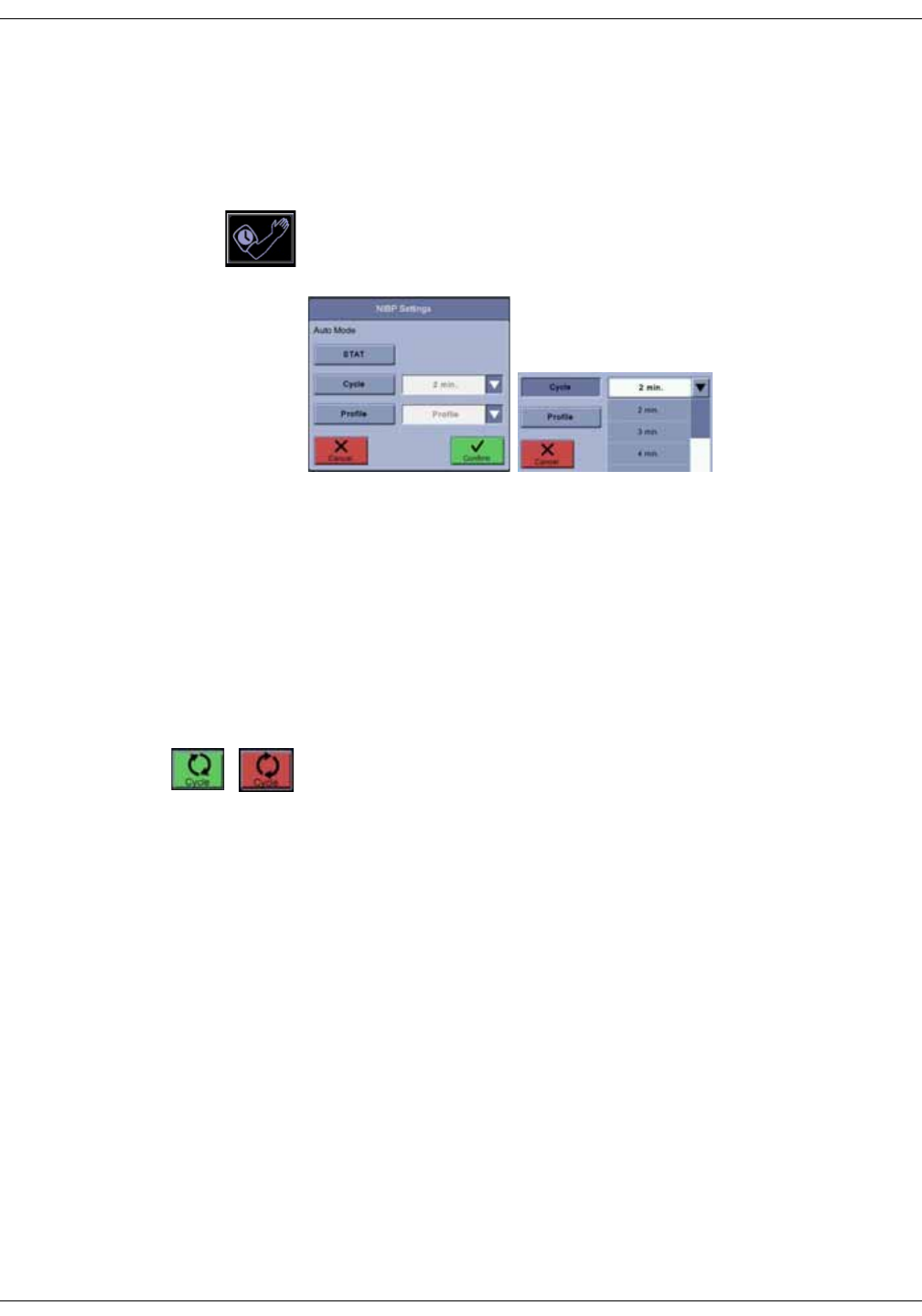
6-10 VC150 Vital Signs Monitor KO00065K
NIBP: NIBP modes of operation
Auto cycle determinations
Auto cycle mode automatically starts determinations at user-defined intervals.
In the auto cycle mode, the pressure must be below 5 mmHg (neonate) or 15
mmHg (adult) for at least 30 seconds before the next auto determination will be
started.
1. Select the auto mode icon on home screen.
2. Select Cycle in the drop-down list.
3. Select the cycle length (measurement at every 2 min, 3 min, 4 min, 5 min, 10
min, 15 min, 20 min, 30 min, 60 min, 90 min and 120 min).
NOTE
Single determinations can be taken while in auto or profile cycle mode
without affecting the starting time for the next auto or profile determination.
However, venous return time will be honored before the next auto or profile
determination starts. If a single measurement lasts longer than when the
next auto cycle is supposed to start, the next auto cycle measurement is
skipped. You can also change the time interval while in auto cycle mode.
4. Select Confirm to confirm the selection or select Cancel to cancel selection.
5. Select the green Cycle auto mode icon on the left side of the screen to start
the cycle. When a determination is complete, the time till the next
determination appears above the auto mode icon. If it becomes necessary
to stop the determination at any point, select the red Cycle auto mode icon.
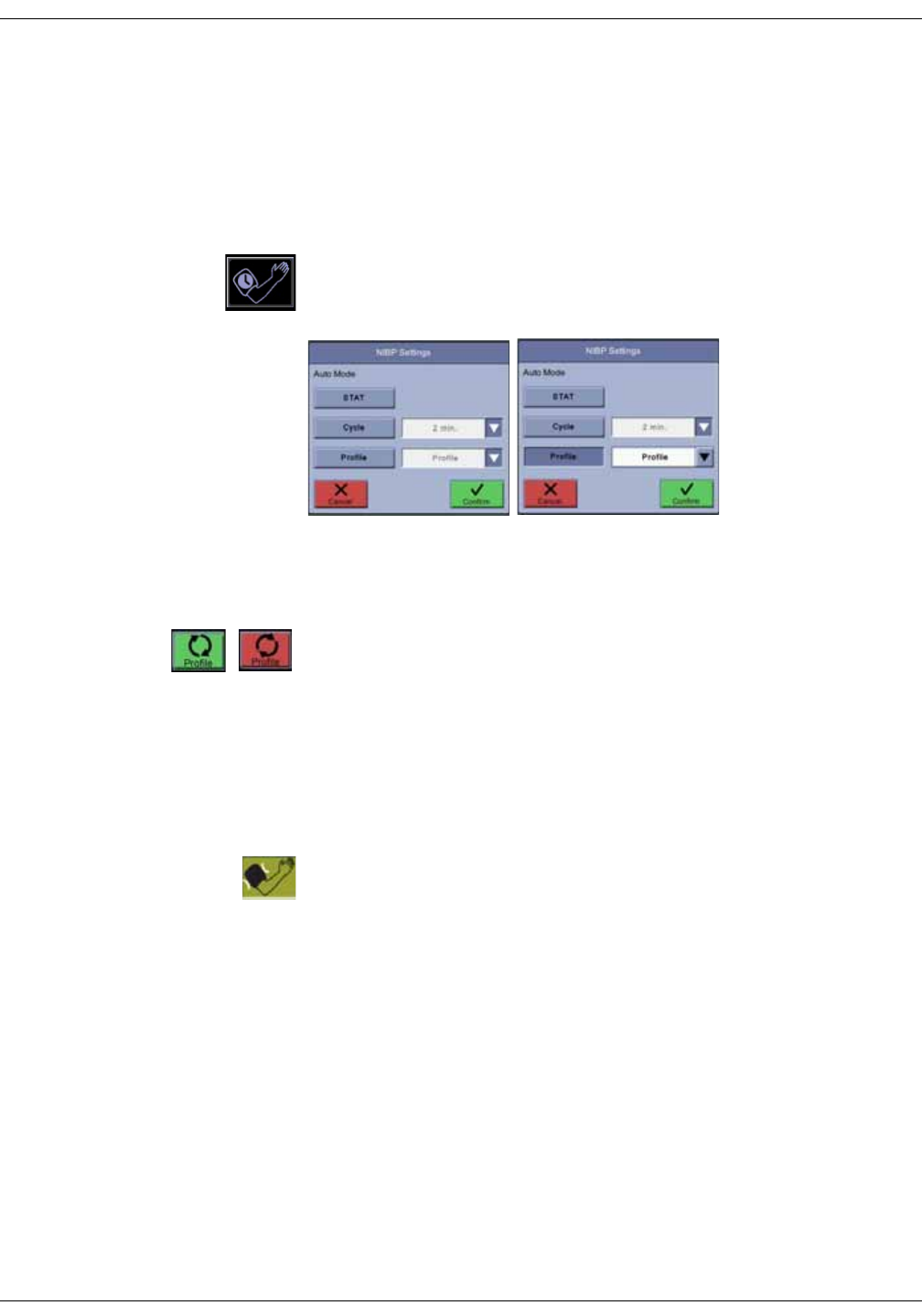
KO00065K VC150 Vital Signs Monitor 6-11
NIBP: NIBP modes of operation
Profile cycle determinations
A profile cycle is a pre-defined set of intervals for a series of NIBP measurements.
The number of determinations and time for an interval can be adjusted in
configuration mode. Five available profiles can be renamed in configuration
mode to make these descriptive. If a profile does not have any number of
determinations and time intervals, its name is not displayed. If no profiles are
defined, the Profile icon is not available.
1. Select the auto mode icon on the home screen.
2. Select Profile.
3. Select a profile in the drop-down list. The names may differ from sample
profiles in the image above.
4. When you have selected a profile name, select Confirm.
5. Select the Profile auto mode icon on the left side of the screen to start the
cycle. When a determination is complete, the time till the next determination
appears above the auto mode icon. If it becomes necessary to stop the
determination at any point, select the red Profile auto mode icon.
Venous return for cycle and profile
If a cycle or profile measurement is still in process when the next cycle
measurement should take place, the next cycle measurement will be skipped. In
case the next cycle measurement should take place right after the current
measurement, the monitor will delay the measurement for venous return. If
there is too much pressure or another problem, a lime green cuff image is
displayed. Selecting this icon will acknowledge the error condition and return the
green inflate icon on screen.

6-12 VC150 Vital Signs Monitor KO00065K
NIBP: NIBP alarm limits
NIBP alarm limits
The NIBP alarm limits are displayed as stated below:
• When a new patient is admitted, dashes are displayed instead of NIBP alarm
limits.
• When a cuff is detected, corresponding NIBP alarm limits (adult or neonatal)
are displayed.
NOTE
The NIBP alarm limit shortcut on the home screen becomes available when
the monitor detects either neonate or adult/pediatric hose and a first NIBP
determination has been completed.
• When a determination is complete, the NIBP alarm limits for the detected
cuff are displayed for a predefined expiration time (set in configuration
mode).
• When latching is selected for an NIBP alarm, the NIBP alarm limits will not
expire.
• Alarm limits remain on screen while the patient is admitted.
• Numeric key pad shortcut for alarm limits is disabled when the limits are not
displayed.
NIBP settings
You should always check the NIBP technology configuration setting before using
the monitor. Monitors located in the same clinical area may have different NIBP
technology configuration settings that could result in operational differences
and a delay in performing vital signs measurements. Refer to “NIBP setup” on
page 3-21 for items to check.
Taking NIBP measurements
During the whole NIBP procedure, the operator should remain in a position
where the patient and the monitor are within easy reach.
Procedure
1. For improved measurement accuracy, have patient in a comfortable
position with legs uncrossed and back and arms supported. The middle of
the cuff should be at the level of the heart during the measurement. The
patient should relax for 5 minutes before the first measurement is
performed. The patient should not talk during the procedure.
NOTE
If the patient is pregnant or is pre-eclamptic, consult with the doctor about
whether NIBP can be performed.
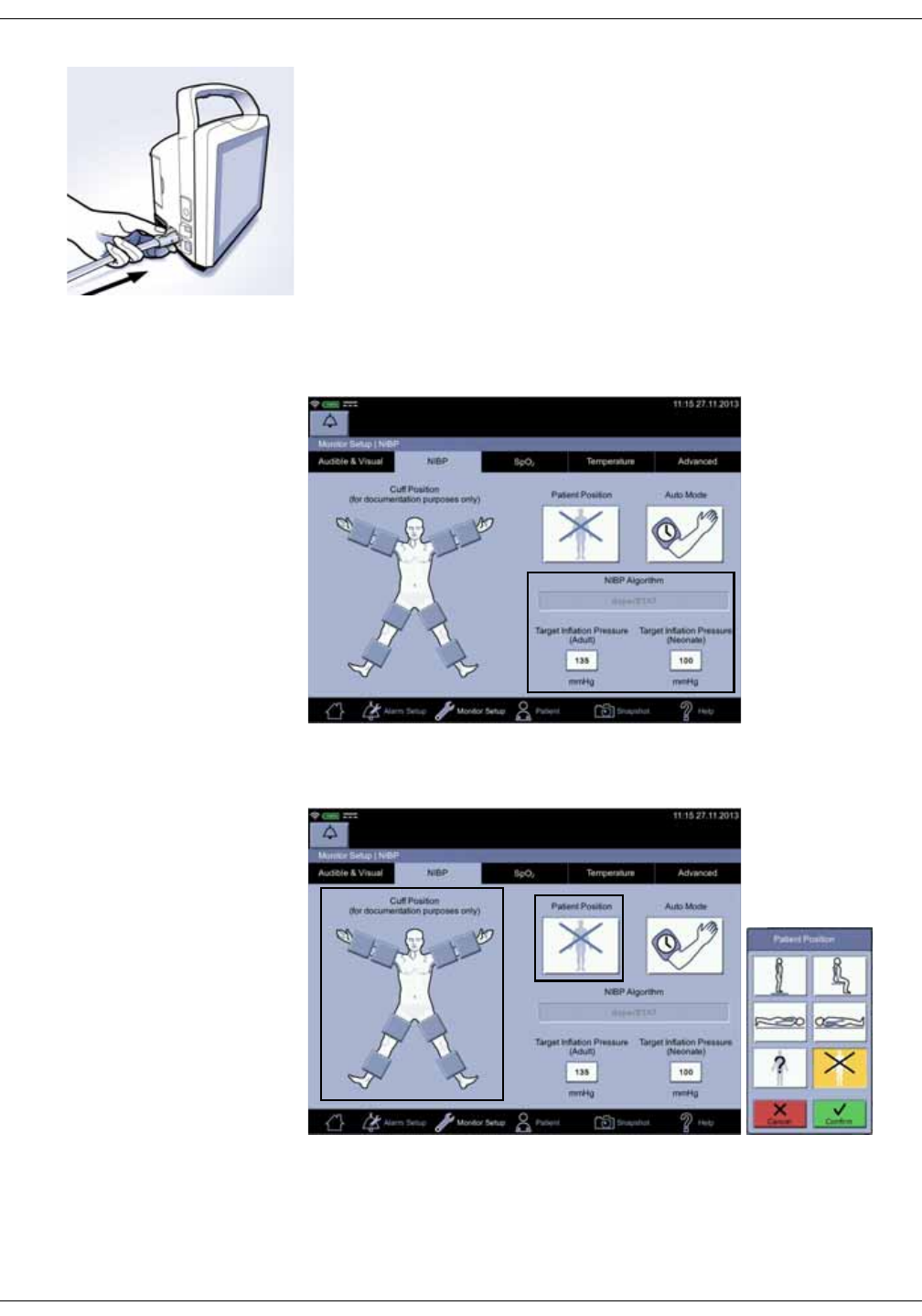
KO00065K VC150 Vital Signs Monitor 6-13
NIBP: Taking NIBP measurements
2. Connect the end of the air hose with quick-release clips to the NIBP
connector on the left side of the monitor. Make sure that the hose is not
kinked or compressed.
NOTE
To disconnect the hose from the monitor, squeeze the quick-release clips
together and pull the plug from the NIBP connector.
3. Set patient-specific Upper and Lower limits (possible only in monitoring
mode). Refer to “Alarm limit setup” on page 3-14 for instructions and to
“Physiological alarm conditions” on page 4-8 for limit ranges.
NOTE
If you are performing a measurement with a neonatal or pediatric cuff,
adjust the limits.
4. Choose the appropriate blood pressure measurement site and patient
position.

6-14 VC150 Vital Signs Monitor KO00065K
NIBP: Taking NIBP measurements
5. For the upper arm, measure the circumference of the upper arm midway
between the elbow and shoulder to determine what size of upper arm cuff
should be used. Proper cuff sizing is crucial for an accurate BP
measurement. When cuff sizes overlap for a specified cuff, it is
recommended to use the larger size cuff. Familiarize yourself with the
operator warnings.
DANGER
Selecting a correct hose and cuff is very important. Do not mix neonatal
and adult hoses! An adult hose pressure is extremely dangerous for
neonates. The air hoses are color-coded according to patient
population. The gray 12- or 24-foot hose (3.66 m or 7.3 m) is required on
patients who require cuff sizes from infant through thigh cuffs. The light
blue 12-foot hose (3.66 m) is required for the neonatal cuff sizes #1
through #5.
Accuracy of NIBP measurement depends on using a cuff of the proper
size. It is essential to measure the circumference of the limb and to
select the proper size cuff. If it becomes necessary to move the cuff to
another limb, make sure the appropriate size cuff is used.
NOTE
Use only GE BP cuffs. The size, shape, and bladder characteristics can
affect the performance of the instrument. Inaccurate readings may
occur unless GE BP cuffs are used.
6. Check the cuff, tubing, adapters, and hose for any signs of damage or wear.
Replace if any signs of damage. Do not inflate cuff when unwrapped. If
accessories are not clean, obtain clean accessories for this measurement or
refer to “Cleaning” on page B-4.
CAUTION
Do not use the cuff if structural integrity is suspect.
7. Connect the cuff to the air hose. Make sure the connections are secure.
Refer to the instructions on GE BP cuffs and hoses.
CAUTION
Never connect cuffs or hoses made by other manufacturers to GE BP
accessories.
8. Inspect the limb for skin integrity.
WARNINGS
Do not apply cuff to areas where skin is not intact or tissue is injured, or
where dermal disruption is at greater risk. Ensure the rough side of the
closure does not contact the skin; it may cause irritation.
Do not apply cuff to limb used for intravenous infusion, oximetry
measurement, arterial monitoring, where AV fistulas are present, or
areas where circulation is compromised. Assess limb for risk of
lymphedema (due to mastectomy, etc). It is always good clinical
practice to document the site of the limb where the BP is taken.
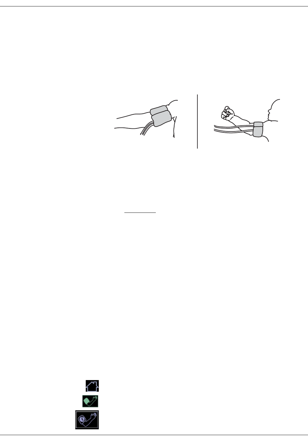
KO00065K VC150 Vital Signs Monitor 6-15
NIBP: Taking NIBP measurements
9. Palpate artery and align the artery mark on the cuff over the patient's
brachial or appropriate artery.
10. Squeeze all air from the cuff and confirm that the connection is secure and
unoccluded and that tubing is not kinked.
NOTE
Avoid compressing or constricting the NIBP pressure tubes.
11. For the upper arm, wrap the cuff around the bicep ensuring the index line
falls between the range marks on the cuff.
12. Ensure the cuff is snug enough to allow only two fingers to be inserted
between the cuff and patient's arm. Ensure that hook and loop closures are
properly engaged so that pressure is evenly distributed throughout cuff.
Cuff should not be so tight as to prevent venous return between
determinations. Always refer to the instructions for use for complete
information on the proper use of your BP cuff.
CAUTION
Using a cuff that is too tight will cause venous congestion and
discoloration of the limb, but using a cuff that is too loose may result in
no readings and/or inaccurate readings.
13. Select the Patient Position and Target Inflation Pressure (if necessary) in
the Monitor Setup > NIBP screen.
NOTES
If the patient is standing, sitting, or inclined, ensure that the cuffed limb is
supported to maintain cuff at level of patient’s heart. If the cuff is not at
heart level, the difference in systolic and diastolic values due to hydrostatic
effect must be considered. To correct for the hydrostatic effect on values not
measured not at the heart level, add 1.90 mmHg to the values for every 2.54
cm (one inch) above heart level or subtract 1.90 mmHg from the values for
every 2.54 cm (one inch) below heart level.
The initial target pressure may need to be adjusted if the patient bruises
easily, is elderly, or for another reason. As there are Target Inflation
Pressure limits for adults and neonates, make sure you adjust the correct
limit.
Choosing the position of the cuff is for documentation purposes only. Please
refer to the cuff’s instructions for use for further information.
14. Select the home icon.
15. If you want to perform a single determination, select the inflate icon to
inflate the cuff and start the measurement process.
16. If you want to perform an automated determination, select the auto mode
icon.
Adult Neonate
Pediatric

6-16 VC150 Vital Signs Monitor KO00065K
NIBP: Taking NIBP measurements
17. Select Cuff position and Auto Mode in the NIBP Settings screen. The mode
must be selected for each measurement. The selected mode is displayed on
the auto mode icon.
18. Select Confirm to confirm the changes and to start the determination or
select Cancel to cancel the changes.
NOTES
If you want to terminate any NIBP measurement when the cuff is inflating,
select the red inflate icon.
If the green inflation waiting icon is selected between cycle or profile
measurements, the monitor will initiate an NIBP determination. This does
not change the previous cycle or profile schedule of NIBP determinations.
When the measurement is complete, the monitor will sound two beeps,
automatically create a snapshot, and display measurement values on screen for
a period defined in configuration mode. Service personnel can change the
display time upon request.
19. To review patient data, enter the Patient screen and select Measurements
to launch a screen with historical patient-related data. The newest
measurement data is posted on the left side of the matrix.
20. Clean and disinfect the NIBP cuffs as instructed in “Cleaning and disinfecting
blood pressure cuffs and air hoses” on page B-6”.
Taking NIBP measurements on different patients
When an NIBP determination is initiated on a new patient, the previous patient
must be discharged first. The monitor will then clear previous NIBP values and
use a default target inflation pressure for this new patient. If several NIBP
determinations are taken, the monitor starts to adjust the target inflation
pressure.
When NIBP measurements are performed: 1) the monitor will use a previous
NIBP value for adaptive target inflation pressure as long as this is displayed on
the screen. 2) the NIBP values are displayed for a maximum of 30 minutes or
until another determination is initiated. When the values on the screen expire or
the patient is discharged, the adaptive target pressure will be automatically
cleared. If a patient’s condition changes between one determination and the
next, the monitor will not detect the change or indicate an alarm condition until
the next NIBP determination values are published on the display.
In auto mode, the previous NIBP systolic pressure is used for adaptive target
inflation pressure independent of the length of time the values are displayed.
NOTES
The adaptive target inflation pressure is cleared when 1) the patient is
discharged or 2) the values on screen expire.
The value will not be cleared if an auto mode measurement is active.

KO00065K VC150 Vital Signs Monitor 6-17
NIBP: Alarms
Alarms
Upon completion of a determination (the monitor has to be in monitoring mode)
that results in systolic, diastolic and MAP values, these values are checked
against the appropriate set of patient type limits based upon the hose type
detected. The final STAT result is checked against alarm limits. When the limit
alarms are active, they can be silenced by selecting the silence icon or
acknowledging an alarm message.
If an auto cycle or profile cycle determination results in a limit alarm, a message
is displayed on screen and a single repeat determination is taken to verify the
alarm. If an auto cycle or profile cycle measurement results in other failure than
NIBP Not Available or NIBP Overpressure, the monitor attempts to perform
maximum of ten consecutive measurements to achieve a proper measurement.
NIBP specifications
Cuff pressure range
(Normal operating range)
0 to 290 mmHg (adult/ped)
0 to 145 mmHg (neonate)
Blood pressure accuracy (Auscultatory) Complies with ANSI/AAMI Standard SP-10:2002 (mean error 5 mmHg,
standard deviation 8 mmHg).
Blood pressure accuracy (SuperSTAT) Complies with ANSI/AAMI Standard SP-10:2002 (mean error 5 mmHg,
standard deviation 8 mmHg).
Maximum determination time 120 s (adult/ped)
85 s (neonate)
Overpressure cutoff 300 to 330 mmHg (adult/ped)
150 to 165 mmHg (neonate)
BP range (Auscultatory)
Systolic 30 to 245 mmHg (adult/ped)
MAP 15 to 215 mmHg (adult/ped)
Diastolic 10 to 195 mmHg (adult/ped)

6-18 VC150 Vital Signs Monitor KO00065K
NIBP: NIBP troubleshooting
NIBP troubleshooting
Overpressure
If an overpressure condition occurs, the word Overpressure appears below the
diastolic value and the pressure is released. Then a blue error message appears
in the notification area.
1. Select the message to acknowledge it. The icon will turn a green inflate icon.
A STAT or Cycle measurement will not continue before this measurement is
terminated.
2. Check for hose and tubing blockage.
3. Try to measure the NIBP again.
Increase in determination time
Arrhythmias will increase the time required by the NIBP parameter to determine
a blood pressure.
Ask the patient whether there is need for medical consultation due to
arrhythmias.
BP range (SuperSTAT)
Systolic 30 to 290 mmHg (adult/ped)
30 to 140 mmHg (neonate)
MAP 20 to 260 mmHg (adult/ped)
20 to 125 mmHg (neonate)
Diastolic 10 to 220 mmHg (adult/ped)
10 to 110 mmHg (neonate)
Pulse rate range (Auscultatory) 30 to 200 beats/min (adult/ped)
Pulse rate range (SuperSTAT) 30 to 240 beats/min (adult/ped)
30 to 240 beats/min (neonate)
Pulse rate accuracy ± 3.5% or 3 bpm, whichever is higher
NOTES
NIBP performance and accuracy have only been confirmed using GE hoses and cuffs.
The SuperSTAT algorithm is used for all neonate NIBP determinations.

KO00065K VC150 Vital Signs Monitor 6-19
NIBP: NIBP troubleshooting
No determination
If an NIBP determination was unable to be completed, the following may be the
cause:
• Determination failed (no complexes). Reapply cuff and restart the NIBP
determination.
• Inflation timeout. Pressure leak. Check or replace hose or cuff.
• Determination cannot be made due to an excess amount of air in the cuff.
• Maximum allowed time reached for a single determination.
• Timeout at single level. Maximum allowed time reached for a single cuff
pressure time.
• Total timeout. Maximum allowed time reached for a total cuff pressure time.

6-20 VC150 Vital Signs Monitor KO00065K
NIBP: NIBP troubleshooting
This page is intentionally left blank.

KO00065K VC150 Vital Signs Monitor 7-1
7GE TruSignal SpO2
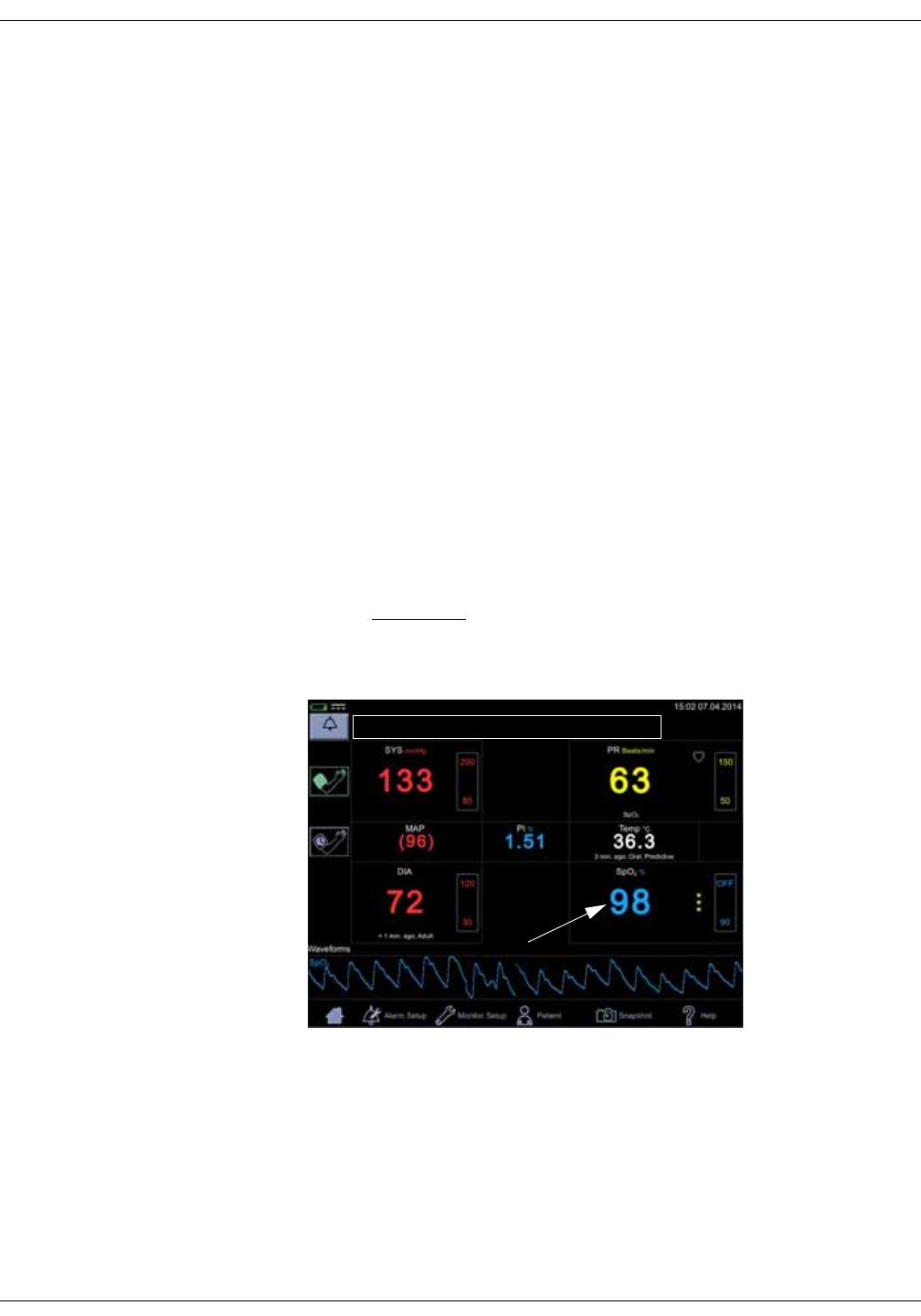
7-2 VC150 Vital Signs Monitor KO00065K
GE TruSignal SpO2: Description
Description
The SpO2 parameter in the monitor is available in three different technologies:
• GE TruSignal
• Nellcor OxiMaxTM
• Masimo rainbow® SET®
The SpO2 technology logo on the left side of the monitor, above the physical
connector, will disclose which technology the monitor is equipped with. If you
want to use a different SpO2 technology than your monitor is currently equipped
with, contact service to discuss the procedure.
The SpO2 function is calibrated to read functional arterial oxygen saturation.
When a suitable SpO2 sensor is connected to the monitor and to the patient, the
measurement values will be shown on the screen. Pulse rate derived from SpO2
appears in the PR (Pulse Rate) window and updates continuously. The primary
source of pulse rate is always SpO2, i.e., if SpO2 is measuring when an NIBP
determination is completed, the pulse rate derived from NIBP is not displayed. A
tone sounds at a rate corresponding to the pulse rate and at a pitch
corresponding to the SpO2 saturation level. The pitch is highest at 100% oxygen
saturation, and it continuously decreases as the saturation level falls.
CAUTION
The pulse rate derived from SpO2 is a value calculated from oxygen
levels. The pulse rate is not equal to the patient’s actual heart rate.
Audible and visual alarms occur when SpO2 levels are outside the alarm limits.
and the monitor is in monitoring mode. When a parameter status alarm occurs,
an alarm message appears at the top of the screen (rectangle in the image
above).

KO00065K VC150 Vital Signs Monitor 7-3
GE TruSignal SpO2: Description
SpO2 safety
WARNINGS
Many factors may cause inaccurate readings and alarms, decreased
perfusion, and/or low signal strength:
Interfering substances:
- Carboxyhemoglobin may erroneously increase SpO2 readings.
- Methemoglobin (MetHb) usually represents less than 1% of the total
Hgb, but in the case of methemoglobinemia that can be congenital or
induced by some IV dyes, antibiotics (such as sulphas), inhaled gases,
etc., this level increases sharply. Methemoglobin may cause inaccurate
SpO2 readings.
- Intravascular dyes (such as indocyanine green, methylene blue, etc.) at
certain concentrations may cause inaccurate SpO2 readings and/or
decreased perfusion and corresponding signal strength, potentially
causing inaccurate SpO2 readings.
-Nail polish and artificial nails may cause inaccurate readings.
Physiological characteristics:
Some physiological characteristics may cause decreased perfusion
and/or low signal strength and may potentially cause inaccurate SpO2
readings:
- Cardiac arrest, hypotension, shock, severe vasoconstriction, severe
anemia, hypothermia, venous pulsations, congestions, darkly
pigmented skin, ventricular septal defects (VSDs)
Environmental conditions:
Some environmental conditions may cause interference or artifact and
may potentially cause inaccurate SpO2 readings.
- Excessive ambient light sources (e.g., infrared heat lamps, strobe
lights, bilirubin lights, direct sunlight, operating room lights). To prevent
such interference, cover the sensor with opaque material.
- Electrical interference/Electrosurgery
- Defibrillation - May cause inaccurate reading for a short amount of
time.
- Excessive patient/sensor motion. Artifact can simulate an SpO2
reading, so that the monitor fails to sound an alarm. In order to ensure
reliable patient monitoring, the proper application of the probe and the
signal quality must be checked at regular intervals.
Sensor placement:
- Sensor placement on the same extremity as a blood pressure cuff,
arterial catheter or intravascular line; or arterial occlusion proximal to
the sensor; or a sensor below the heart level may cause decreased
perfusion and/or low signal strength and potentially cause inaccurate
SpO2 readings.
- Poor sensor fit may cause decreased or low signal strength and
potentially cause inaccurate SpO2 readings.
- Do not allow tape to block the sensor light emitter and detector as this
may cause decreased perfusion and/or low signal strength and
potentially cause inaccurate SpO2 readings.
- Before using the GE TruSignal sensor, carefully read the GE sensor
instructions for use.

7-4 VC150 Vital Signs Monitor KO00065K
GE TruSignal SpO2: Description
WARNING
As with any wrap or clip-on sensor, pressure is exerted. Be cautious in
using a wrap or clip-on sensor on patients with compromised
circulation (e.g., peripheral vascular disease or vasoconstricting
medications).
Allow sensor and cable to dry completely after cleaning. Moisture and
dirt on the connector can affect the measurement accuracy.
Inaccurate SpO2 data can result if a sensor is past its useful life.
Therefore, re-evaluate the measurement periodically by performing
additional assessment of the patient equipment, including
consideration of use of alternate monitoring methods such as direct
measurement of arterial oxyhemoglobin saturation (SaO2).
If the accuracy of any measurement does not seem reasonable, first
check the patient’s vital signs, then check for conditions that may cause
inaccurate SpO2 readings. If the problem is still not resolved, check the
SpO2 module or sensor for proper functioning.
Oximetry performance may be impaired when patient perfusion is low
(less than 0.3%) or signal attenuation is high.
A pulse oximeter or CO-oximeter should not be used as an apnea
monitor.
A pulse oximeter should be considered an early warning device. As a
trend toward patient deoxygenation is indicated, blood samples should
be analyzed by a laboratory CO-oximeter to completely understand the
patient's condition. Check that the pulse oximetry waveform is
physiological in shape to ensure waveform quality and minimize noise
spikes caused by motion conditions.
If you deactivate the SpO2 Sensor Off alarm, keep the patient under
close surveillance.
Single-use products are not designed to be reused. Reuse may cause a
risk of cross-contamination, affect the measurement accuracy and/or
system performance, and cause a malfunction as a result of the
product being physically damaged due to cleaning, disinfection, re-
sterilization and/or reuse.
Clean the surface of the probe before and after each patient use.
Do not loop the sensor cable into a tight coil or wrap around the device,
as this can damage the sensor cable.

KO00065K VC150 Vital Signs Monitor 7-5
GE TruSignal SpO2: Description
CAUTIONS
Do not sterilize reusable sensors by irradiation, steam, or ethylene
oxide. See the sensor manufacturer's instructions for cleaning,
sterilization, or disinfecting methods.
Do not place SpO2 sensor on patient during magnetic resonance
imaging (MRI). Adverse reactions include potential burns to patients as a
result of contact with attachments heated by the MRI radio frequency
pulse, potential degradation of the magnetic resonance image, and
potential reduced accuracy of SpO2 measurements. Always remove
oximetry devices and attachments from the MRI environment before
scanning a patient.
Pulse oximetry readings and pulse signals can be affected by certain
environmental conditions, sensor application errors, and certain patient
conditions. See the appropriate sections of this manual for specific
safety information.
Placing a sensor distal to an arterial line may interfere with adequate
arterial pulsation and compromise the measurement of SpO2.
The sensor disconnect error message and associated alarm indicate
that the sensor is either disconnected or the wiring is faulty. The user
should check the sensor connection and, if necessary, replace the
sensor, interconnect cable, or both.
Placing a sensor on a polished or an artificial nail may affect accuracy.
Patient safety:
Do not place any clip-on sensor in a patient’s mouth, on their nose or
toes, on their thumb, or across a child’s foot or hand.
Prolonged monitoring or incorrect sensor application can cause skin
irritation or impaired circulation. Observe the sensor site frequently to
assure adequate distal circulation. Sensor sites should be checked at
least every 2 hours and rotated at least every 4 hours. Refer to
instructions supplied with sensor.
If the sensor is not applied properly, the patient’s skin could be injured or
the ability of the monitor to measure oxygen saturation could be
compromised. For example, a clip-on sensor should never be taped
shut. Taping the sensor could damage the patient’s skin or impair the
venous return, thus causing venous pulsation and inaccurate
measurement of oxygen saturation.
Excessive pressure from the sensor may cause necrosis of the skin.

7-6 VC150 Vital Signs Monitor KO00065K
GE TruSignal SpO2: Description
CAUTIONS
Monitor performance:
Place the sensor so that the LEDs and the photodiode are opposite each
other.
Monitor performance:
When an SpO2 sensor is located on the same limb as the NIBP cuff, SpO2
readings will not be valid while the cuff is inflated. If valid SpO2 readings
are required during the entire blood pressure determination, attach the
SpO2 sensor to the limb opposite the one with the blood pressure cuff.
NOTES
• A patient’s vital signs may vary dramatically during the use of
cardiovascular agents such as those that raise or lower blood pressure or
those that increase or decrease pulse rate.
•SpO
2 and pulse rate values are filtered by an averaging technique, which
determines how quickly the reported values respond to changes in the
patient’s saturation. The averaging time effects time to alarm for SpO2
saturation and pulse rate limits. For TruSignal SpO2 technology, the
averaging time is 8 seconds and cannot be changed by the user.
• Pulse rate measurement is based on the optical detection of a peripheral
flow pulse and therefore may not detect certain arrhythmias. The pulse
oximeter should not be used as a replacement or substitute for ECG based
arrhythmia analysis.
• Software development, software validation, and risk and hazard analysis
have been performed to a registered quality system.
• GE TruSignal sensors are not made with natural rubber latex or known
environmental contaminants.
• A functional tester cannot be used to assess the accuracy of a pulse
oximeter probe or a pulse oximeter monitor.
• The pulse oximeter cannot distinguish between oxyhemoglobin and
dyshemoglobins.
• Poor perfusion may affect the accuracy of measurement, especially when
using an ear sensor.
• Check that the red light is lit in the sensor.
• Check that the waveforms (if enabled in monitor setup) and parameter
values are displayed when the sensor is connected to the patient.
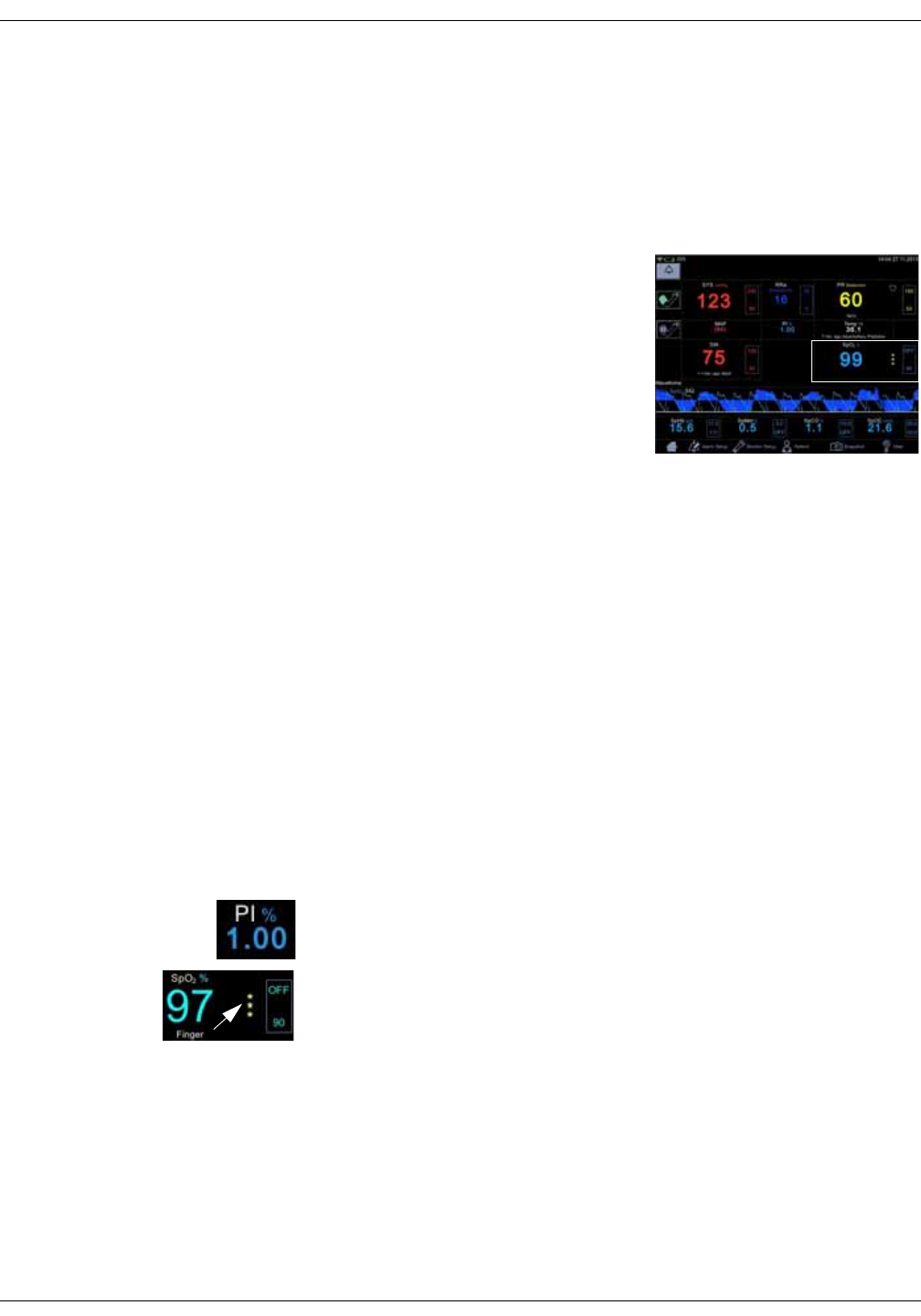
KO00065K VC150 Vital Signs Monitor 7-7
GE TruSignal SpO2: SpO2 on the screen
SpO2 on the screen
When SpO2 is not receiving measurement data, a double dash (--) appears in this
window. When the sensor switches to operation mode, the SpO2 parameter
starts to receive data. If the data is valid, the derived SpO2 value appears in this
window and updates continuously. The values are displayed in %.
SpO2 values are displayed on the lower right
side of the monitor screen. The SpO2 and PI
values are displayed in cyan color by
default. This can be changed in
configuration mode. If the monitor is
providing the temperature measurement
the SpO2 value will be located under the
displayed temperature value.
The SpO2 field consists of the SpO2 label, the
measured value in the middle and the measurement site underneath the
parameter value. The measurement site choices are: Finger, Nose, Toe, Earlobe.
The site name Other can be used to indicate it was none of the above. The
default site is None. Next to the measured value is a column of asterisks
representing signal quality, as well as upper and lower limits for the SpO2 value.
If the sensor is detached from the patient, the SpO2 status switches to ‘off
patient’ and displays --.
NOTES
If pulse rate data from SpO2 data is available, the Pulse Rate window is
associated with this parameter and a heart symbol is displayed on screen.
Refer to “Pulse rate” on page 10-1 for more information.
If accuracy for a SpO2 derived parameter is not yet guaranteed, a dimmed
value is displayed on screen.
Perfusion index measurement
The perfusion index (PI) measurement is a clinical tool that provides a dynamic
numeric reflection of perfusion at the sensor site. PI is a relative value that varies
from patient to patient. The perfusion index value appears in its own field under
the label PI. The user can use the PI value to compare the strength of the pulse
signal at different sites on a patient in order to locate the best site for the sensor,
i.e., the site with the strongest pulse signal.
Signal quality values are mathematically calculated perfusion values
represented by asterisks. The SpO2 signal strength should be adequate. This is
indicated by the display of two or three asterisks or the absence of a Low Signal
Quality message. The more asterisks there are the better the signal quality. The
better the arterial blood flow is, the better signal quality is obtained. A strong
pulse signal increases the validity of SpO2 and pulse rate data.
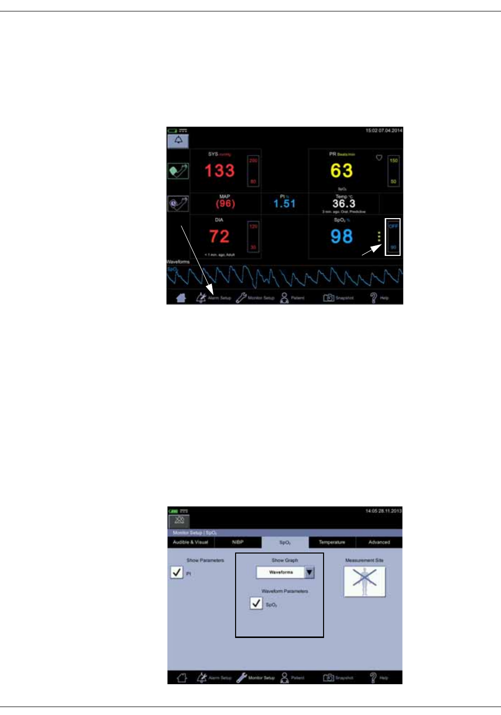
7-8 VC150 Vital Signs Monitor KO00065K
GE TruSignal SpO2: SpO2 on the screen
Changing the SpO2 alarm limits
SpO2 alarm limit adjustments can be set either A) by entering upper and lower
limit values directly in a limit box on the home screen as instructed in “Using the
numeric keypad” on page 3-12 or B) by adjusting limit values in the Alarm Setup
screen as instructed in “Procedure for testing alarms” on page 3-11.
Pleth
The Plethysmographic waveform (Pleth) represents a real-time waveform for the
relative SpO2 pulsatile amplitude. The Pleth waveform is always automatically
scaled to fit the window for the best display quality. The waveform uses the
same color as the SpO2 field.
Pleth waveform settings
Select Waveforms in the drop-down menu under Show Graph in the Monitor
Setup > SpO2 to display the Pleth. Also select parameters to be displayed as
waveforms (availability depends on which SpO2 technology the monitor is
equipped with and which options have been purchased).
A
B
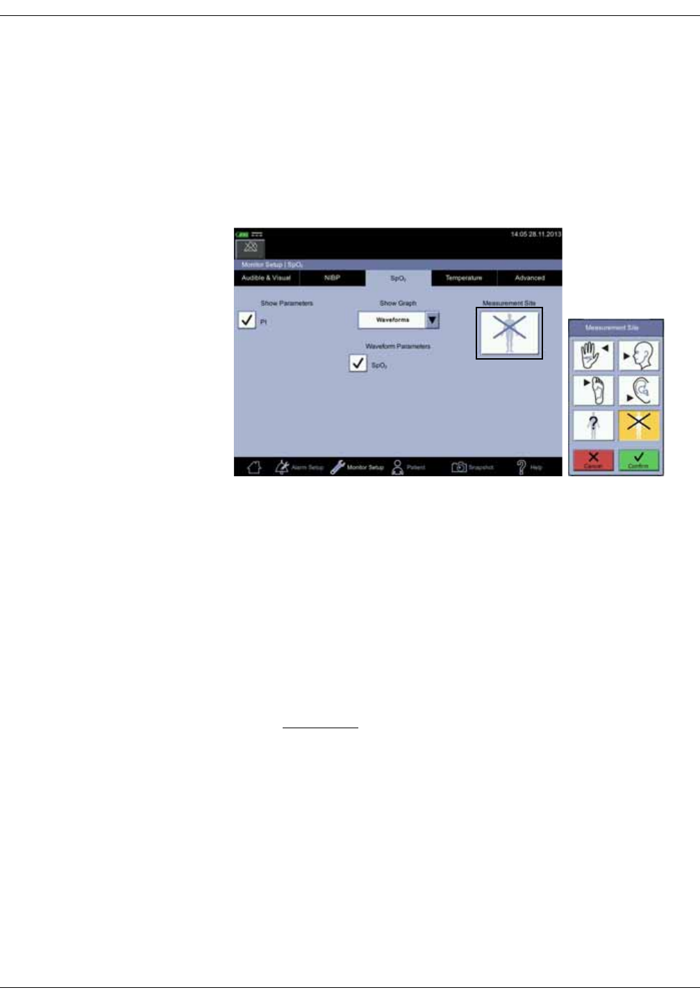
KO00065K VC150 Vital Signs Monitor 7-9
GE TruSignal SpO2: SpO2 procedure
SpO2 measurement site
For documentation purposes, you can select the measurement site for SpO2 in
Monitor Setup > SpO2 before you start measuring SpO2. A pop-up screen with
the following images will appear: Finger, Nose, Toe, Earlobe, Other or None. It
does not matter whether the site is on the left or right side of the patient. After
the site is selected, it will be displayed on the home screen in the SpO2
parameter window. The selection can be changed between the measurements.
Admitting a new patient will reset the selection of the measurement site.
SpO2 procedure
1. Check the label on the monitor to determine which SpO2 technology the
monitor is using. To assure optimal performance, use only accessories that
are intended for that technology. If you cannot read the label, ask the nurse
manager or service which SpO2 technology is used.
2. Select a sensor that is appropriate for the patient, the clinical situation and
for the SpO2 technology used. Do not use an adult sensor on a neonatal/
pediatric patient and vice versa.
WARNING
Do not use a sensor, cables, or connectors that appear damaged or
with exposed electrical contacts.
Never repair a damaged sensor or cable; never use a sensor or cable
repaired by others.
3. Ensure the VC150 is connected to power or the battery is fully charged.
4. Ensure the VC150 is powered on. The monitor has to display clinical mode
and SpO2 parameter on screen.
5. Connect an interface cable to the monitoring system sensor port.

7-10 VC150 Vital Signs Monitor KO00065K
GE TruSignal SpO2: SpO2 sounds
6. Follow the manufacturer’s guide to plug in the SpO2 cable into the monitor
and apply the proper SpO2 sensor. The VC150 reports the appropriate
sensor type in the message field when it detects the sensor.
7. Following the directions for use supplied with the sensor, apply the sensor to
the patient.
8. Select the measurement site in Monitor Setup > SpO2, if desired. A shortcut:
Select SpO2 parameter area on the home screen to jump to the SpO2 screen.
9. Proceed with monitoring. SpO2 measurements run continuously and can run
simultaneously with other measurements.
10. Clean the sensor as instructed in “Cleaning SpO2 sensors” on page B-8”.
SpO2 sounds
The monitor provides an audible tone for each pulse detected by the SpO2
parameter. The pitch of the audible tone is directly related to the calculated
saturation value. As the saturation value increases, the pitch rises. As the
saturation value decreases, the pitch frequency goes down. This audible tone is
silenced while an alarm sounds or the Day Volume or Night Volume is set to 0.
Refer to “Audible & Visual” on page 3-19 in this section.
Alarms
If the SpO2 parameter determines the signal to be valid, SpO2 values are
displayed. In case the signal quality deteriorates to a questionable level, the
SpO2 or Pulse Rate values disappear from the screen and an alarm message for
lost pulse signal is generated.
Alarm timer
The user can select between monitoring mode and spot-check mode. In spot-
check mode, clinical alarms and related functions are not available. If an SpO2
measurement continues for 5 minutes uninterrupted, the monitor automatically
moves from spot-check mode to monitoring mode. The alarms will be enabled in
monitoring mode.
If the probe is taken off and you want to measure the same patient without
alarms, select spot-check mode again.
NOTE
To prevent misuse of the device, duration of the SpO2 spot-check mode is
limited to 5 minutes.

KO00065K VC150 Vital Signs Monitor 7-11
GE TruSignal SpO2: TruSignal compatible accessories
If SpO2 is unable to be measured for some reason, then a technical status
message that indicates the reason for not measuring will appear below the
parameter value. If an abnormal technical status remains for ten seconds, then
a low priority alarm is created.
An abnormal technical status will create an alarm in both spot-check and
monitoring mode.
TruSignal compatible accessories
All approved and VC150 compliant accessories are listed in the VC150 supplies
and accessories document. Use only accessories listed in that document. If you
already have an accessory that you want to use with the VC150 monitor, check
whether it is listed in that document. If it not listed, do not use it with the VC150
monitor.
GE TruSignal enhanced SpO2
GE TruSignal uses a clinically developed algorithm to perform during weak or
motion-induced signals for reliable saturation readings.
WARNING
GE TruSignal technology-labeled monitors are compatible only with the
GE TruSignal interconnect cables, sensors and accessories, which are
available from your Innokas Medical representative. Other sensors may
cause improper SpO2 performance. Use of another pulse oximetry cable
will have an adverse effect on performance. Do not attach any cable
that is intended for computer use to the sensor port.
NEONATAL - The display of inaccurate pulse oximetry (SpO2) values has
been linked to the presence of poor signal strength or artifact due to
patient motion during signal analysis. This condition is most likely to be
encountered when the monitor is used on neonates or infants. These
same conditions in adults do not impact the SpO2 values to the same
extent. We recommend the application of the following criterion when
using the pulse oximetry function on neonates and infants: The SpO2
signal strength should be adequate. This is indicated by the display of
two or three asterisks or the absence of a Low Signal Quality message.
Procedures or devices previously applied in your facility for SpO2
monitoring should be used in the event the SpO2 value from the monitor
cannot be validated by the above criterion.
The pulse oximeter cannot distinguish between oxyhemoglobin and
dyshemoglobins.
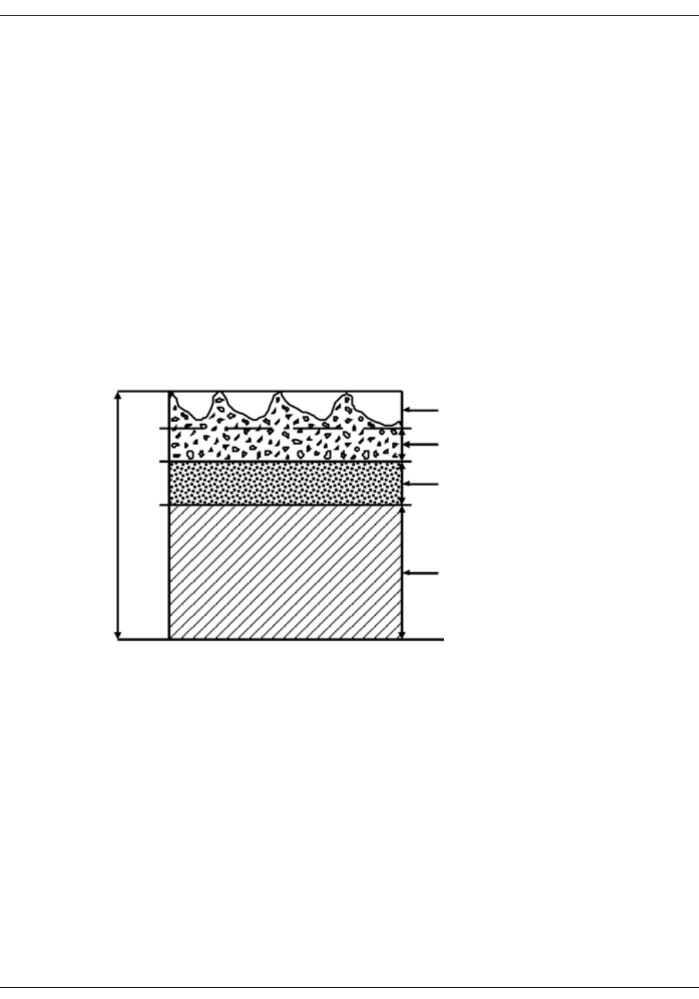
7-12 VC150 Vital Signs Monitor KO00065K
GE TruSignal SpO2: GE TruSignal enhanced SpO2
TruSignal SpO2 measurement characteristics
The TruSignal pulse oximetry measurement uses a two-wavelength pulsatile
system - red and infrared light - to distinguish between oxyhemoglobin (O2Hb)
and reduced hemoglobin (HHb).
The light is emitted from the oximeter sensor, which contains the light source
and a photodetector.
The light source consists of red and infrared light-emitting diodes (LEDs).
The photodetector is an electronic device that produces an electrical current
proportional to incident light intensity.
The two light wavelengths generated by the LEDs are transmitted through the
tissue at the sensor site and are modulated by arterial blood pulsation. Since
other fluids and tissues present generally do not pulsate, they do not modulate
the light. The pulsatile portion of the incoming signal is used to detect and isolate
the attenuation of light energy due to arterial blood flow.
Figure 7-1. Comparative light absorption
The photodetector in the sensor converts the light intensity information into an
electronic signal. Since O2Hb and HHb absorb different amounts of the light that
is emitted from the oximeter sensor, different amounts of light reach the
photodetector at the selected wavelengths. The electronic signal varies
according to which light source is “on” (red or infrared) and the oxygenation of
the arterial hemoglobin. This information is used to calculate the relative
percentage of O2Hb and HHb.
Absorption
Time
Variable absorption (due to arterial pulse)
Arterial blood absorption
Venous blood absorption
Other tissue absorption
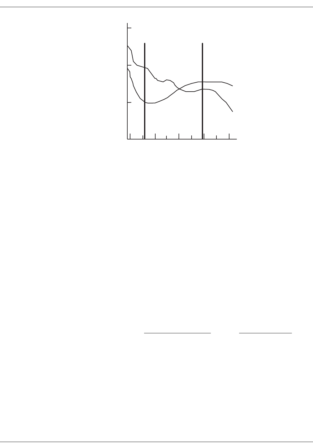
KO00065K VC150 Vital Signs Monitor 7-13
GE TruSignal SpO2: GE TruSignal enhanced SpO2
Figure 7-2. Extinction versus wavelength graph
Interfering substances
Increased patient carboxyhemoglobin may falsely increase SpO2 readings in all
brands of pulse oximeters. Therefore, saturation readings may be higher for
smokers, victims of smoke inhalation, and patients with carbon monoxide (CO)
intoxication. The level of increase is approximately equal to the amount of
carboxyhemoglobin present.
Methemoglobin from certain therapies, dyes that change arterial pigmentation,
and substances at the sensor site that contain dyes (fingernail polish, for
example) may also cause erroneous readings.
Calibration
TruSignal technology uses the functional calibration method. Functional
saturation is represented mathematically as the percentage of hemoglobin
capable of carrying oxygen that is carrying oxygen.
The calculation of SpO2 assumes 1.6% carboxyhemoglobin (COHb), 0.4%
methemoglobin (MetHb), and no interfering dyes. Appreciable variation from
these values will influence SpO2 accuracy.
NOTE
A hospital-grade CO-oximeter, which requires a sample of arterial blood and
typically uses four or more wavelengths of light, calculates
carboxyhemoglobin (COHb) and methemoglobin (MetHb) as well as O2Hb
and HHb. CO-oximeter readings and pulse oximeter readings will differ
when COHb or MetHb is present.
Wavelength (nm)
Extinction (10x)
Red
660 nm
Infrared
890 nm
1.0
10
0.1
HHb
HbO
800 900 1000700600
O2Hb
HbTOTAL- COHb - MetHb O2Hb
O2Hb + HHb
) x 100 = (Functional SpO2 = ( ) x 100

7-14 VC150 Vital Signs Monitor KO00065K
GE TruSignal SpO2: GE TruSignal SpO2 default settings
GE TruSignal SpO2 configuration
Refer to “SpO2 setup” on page 3-23 to view or change the settings for Waveform
and Site.
Recommended actions
• Consult the sensor instructions for use for proper sensor application.
• Inspect extension cables and sensors periodically for damage and
discontinue the use of these if damage is found.
• Implement a periodic testing strategy.
• Review safety labeling based on the intended use of the equipment.
GE TruSignal SpO2 default settings
GE TruSignal SpO2 specifications
GE Trusignal SpO2 - Default Setup > Alarm Defaults
SpO2Upper limit: OFF
Lower limit: 90%
Priority: Medium
Latching/Non-latching: Latching
PI Upper limit: OFF
Lower limit: OFF
Priority: OFF
Latching/Non-latching: Non-latching
Measurement range
SpO20 to 100%
Pulse rate 30 to 300 bpm
Perfusion Index Value (PI) 0.1 to 32.0%
Data update
Data update period <2 s

KO00065K VC150 Vital Signs Monitor 7-15
GE TruSignal SpO2: GE TruSignal SpO2 specifications
Accuracy
Accuracy, Arms (root mean square of paired values; previously represented by ± 1 SD)
Saturation Accuracy
Adult* 70 to 100% ±2 digits
Neonate* 70 to 100% ±3 digits (without motion)
Adult/Neonate** 70 to 100% ±3 digits (during motion)
Low perfusion 70 to 100% ±2 digits
Pulse Rate Accuracy
Adult /Neonate 30 to 250 bpm ± 2 bpm (rms, without motion)
30 to 250 bpm ± 5 bpm (rms, during motion)
Low perfusion 30 to 250 bpm ± 3 bpm (rms)
*Test methods used to establish SpO2 accuracy: GE Trusignal Technology with OxyTip+/GE TruSignal sensors have
been validated for no motion and motion accuracy in controlled hypoxia studies with healthy non-smoking adult
volunteers over the specified SpO2 range. SpO2 readings were compared to SaO2 values of drawn blood samples
measured by CO-oximetry. Subjects comprised both adult men and women and spanned a range of skin
pigmentation. GE TruSignal technology with OxyTip+/GE TruSignal sensors have been validated for low perfusion SpO2
accuracy over the specified range in a bench top testing against BioTek Index 2 patient simulator with 0.3% signal
amplitude.
**GE TruSignal Technology with GE OXY-AF (equivalent to TS-AF) and GE OXY-SE (equivalent to TS-SE) sensors have
been clinically validated for neonatal accuracy. Test subjects included 28 neonates and 1 infant (15 females and 14
males) with ages ranging from newborn to 37 days, weights from 560g to 3060g and skin tones from light to dark.
Accuracy (Arms) of the collected convenience samples was 2.7 for the OXY-AF sensor (52 data points were collected in
the range of 87%-100%) and 2.7 for the OXY-SE sensor (53 data points were collected in the range of 81%-100%).
***GE TruSignal Technology with GE Oxy-AF (equivalent to TS-AF) and GE Oxy-AP (equivalent to TS-AP) sensors have
been validated for motion accuracy in controlled hypoxia studies with healthy non-smoking adult volunteers over the
specified saturation SpO2 range(s). The following motion types were used: mechanically induced 3 Hz tapping motion
at an amplitude of 1-2 cm, patient induced non-repetitive rubbing motion, and patient induced non-repetitive hand
motion in supine position. Pulse oximeter SpO2 readings were compared to SaO2 values of drawn blood samples
measured by CO-oximetry. Subjects comprised both adult men and women and spanned a range of skin
pigmentations.
****GE TruSignal technology with OxyTip+/GE TruSignal sensors have been validated for pulse rate accuracy over the
specified range in bench top testing against a patient simulator. Accuracy was calculated as the root-mean-square
(rms) difference between paired pulse rate data recorded with the pulse oximeter equipment and with the patient
simulator.
NOTE
Accuracy may vary for some sensors; always check the instructions for the sensor.

7-16 VC150 Vital Signs Monitor KO00065K
GE TruSignal SpO2: GE TruSignal SpO2 sensor accuracy specifications
GE TruSignal SpO2 sensor accuracy specifications
NOTE
For detailed information on patient population, sensor site and application
refer to GE Trusignal sensor instructions for use.
Part Sensor
model Part description SpO2 range 70% to 100%
SpO2 - Cable TS-G3 GE TruSignal Interconnect cable with GE connector
SpO2 - Sensor TS-F2-GE GE TruSignal Finger Sensor with integrated cable,
2m
±2 digits without motion
SpO2 - Sensor TS-F4-GE GE TruSignal Finger Sensor with integrated cable,
4m
±2 digits without motion
SpO2 - Sensor TS-F-D GE TruSignal Finger Sensor ±2 digits without motion
SpO2 - Sensor TS-SA-D GE TruSignal Soft Adult Sensor with integrated
cable and D connector, 1m
±2 digits without motion
SpO2 - Sensor TS-SA4-GE GE TruSignal Soft Adult Sensor with integrated
cable and GE connector, 4m
±2 digits without motion
SpO2 - Sensor TS-W-D GE TruSignal Wrap Sensor ±2 digits without motion
SpO2 - Sensor TS-E4-GE GE TruSignal Ear Sensor with integrated cable, 4m ±3 digits without motion
SpO2 - Sensor TS-E2-GE GE TruSignal Ear Sensor with integrated cable, 2m ±3 digits without motion
SpO2 - Sensor TS-E-D GE TruSignal Ear Sensor ±3 digits without motion
SpO2 - Sensor TS-SE-3 GE TruSignal Sensitive Skin Sensor ±2 digits without motion
SpO2 - Sensor TS-AF-10 GE TruSignal AllFit Sensor, 10/box ±2 digits without motion
SpO2 - Sensor TS-AF-25 GE TruSignal AllFit Sensor, 25/box ±2 digits without motion
SpO2 - Sensor TS-SP-D GE TruSignal Soft Pediatric Sensor, 1m ±2 digits without motion
SpO2 - Sensor TS-SP3-GE GE TruSignal Soft Pediatric Sensor with integrated
cable, 3m
±2 digits without motion
SpO2 - Sensor TS-AP-10 GE TruSignal AP Sensor, 10/box ±2 digits without motion
SpO2 - Sensor TS-AP-25 GE TruSignal AP Sensor, 25/box ±2 digits without motion

KO00065K VC150 Vital Signs Monitor 7-17
GE TruSignal SpO2: GE TruSignal SpO2 sensor accuracy specifications
SpO2 -
Accessory
OXY-RTW OxyTip+ wide replacement tape, adhesive
SpO2 -
Accessory
OXY-RWL Foam wrap replacement, large, weight range > 3
kg
SpO2 -
Accessory
OXY-RWM Foam wrap replacement, medium, weight range >
3 kg
SpO2 - Kit OXY-BC-5 Bedside clip -5/box
SpO2 - Kit OXY-HB Replacement headband
SpO2 -
Accessory
OXY-RWS Foam wrap replacement, small, weight range < 3
kg
SpO2 -
Accessory
OXY-RTB OxyTip+ replacement tape, AllFit Sensor, Bears -
100/box
SpO2 -
Accessory
OXY-RT OxyTip+ replacement tape, AllFit Sensor, Blue - 100/
box
SpO2 -
Accessory
OXY-SND Infant Foam Sandal, use with OxyTip+ Sensitive
Skin sensor - 3/box
OXY- Sensor (No Longer Sold)
SpO2 - Cable OXY-ES3 OxyTip+ Interconnect cable, Ohmeda, 3 m
SpO2 - Sensor OXY-F-UN Finger Sensor with UN connector, 1 m ±2 digits without motion
SpO2 - Sensor OXY-W-UN Wrap Sensor with UN connector, 1 m ±2 digits without motion
SpO2 - Sensor OXY-E-UN Ear Sensor with UN connector, 1 m ±3 digits without motion
SpO2 - Sensor OXY- SE-3 Sensitive Skin Sensor with UN connector, 4 m ±2 digits without motion
SpO2 - Sensor OXY-AP-25 Adult/Pediatric Adhesive Sensor - 25/box ±2 digits without motion
SpO2 - Sensor OXY-AP-10 Adult/Pediatric Adhesive Sensor - 10/box ±2 digits without motion
SpO2 - Sensor OXY-AF-10 AllFit Adhesive Sensor, 0.9 m - 10/box ±2 digits without motion
SpO2 - Sensor OXY-F4-GE Integrated finger sensor, 4 m ±2 digits without motion
SpO2 - Sensor OXY-E4-GE Integrated ear sensor ±3 digits without motion

7-18 VC150 Vital Signs Monitor KO00065K
GE TruSignal SpO2: Troubleshooting
Troubleshooting
This section discusses potential difficulties and suggestions for resolving them. If
the difficulty persists, contact service or your local Innokas Medical
representative.
SpO2 -
Accessory
OXY-F2-GE OxyTip+ Integrated Finger Care connector 2 m
SpO2 -
Accessory
OXY-E2-GE OxyTip+ Integrated Ear Care connector 2 m
Note: Sensor Accuracy
Because SpO2 measurements are statistically distributed, only about 2/3 of the measurements can be expected to fall
within ±1 Arms of the value measured by a CO-oximeter.
Test methods used to establish SpO2 accuracy: GE TruSignal SpO2 measurement have been validated for no motion
and motion accuracy in a controlled hypoxia studies with healthy non-smoking adult volunteers over the specified
SpO2 range.
SpO2 readings were compared to SaO2 values of drawn blood samples measured by CO-oximetry. Subjects comprised
both adult men and women and spanned a range of skin pigmentation.
Sensor light source
Wavelength of SpO2 probe LEDs Infrared: 880 to 900 nm (nominal)
Red 650 to 670 nm (nominal)
NOTE
This information may be useful
to clinicians, such as those
performing photodynamic
therapy.
Maximum energy of SpO2 probe LEDs Infrared LED 42 µJ/pulse
Red LED 62 µJ/pulse
Problem Cause Solution
The heart icon
indicates a pulse,
but no oxygen
saturation or pulse
rate values appear
on the screen.
• Excessive patient motion may be
making it impossible for the SpO2
function to find a pulse pattern.
• The sensor may be damaged.
• The patient’s perfusion may be too
low to allow the SpO2 function to
measure saturation and pulse rate.
• Check the patient.
• Check instructions provided by the sensor
manufacturer for proper placement.
• If possible, keep the patient still; check whether the
SpO2 sensor is applied securely and properly, and
replace it if necessary; use the PI value to determine
the strength of the signal and move the sensor to a
new site; or use an adhesive sensor.
• Replace the sensor.

KO00065K VC150 Vital Signs Monitor 7-19
GE TruSignal SpO2: Troubleshooting
Large sudden
changes in the
SpO2 or the pulse
rate values.
Asterisks or signal
quality unstable.
• Excessive patient motion may be
making it difficult for the SpO2
function to find a pulse pattern.
• An electrosurgical unit (ESU) may
be interfering with performance.
• Check the patient.
• If possible, keep the patient still; check whether the
sensor is applied securely and properly, and replace
it if necessary; use the PI value to determine the
strength of the signal and move the sensor to a new
site.
If an ESU is interfering:
• Move the SpO2 cable as far from the ESU as possible.
• Plug the monitor and the ESU into different AC
circuits.
• Move the ESU ground pad as close to the surgical
site as possible.
• The sensor may need to be replaced with a new
sensor.
The oxygen
saturation
measurement does
not correlate with
the value
calculated from a
blood gas
determination.
•The SpO
2 calculation may not have
correctly adjusted for the effects of
pH; temperature; CO2; or 2.3-DPG.
• Accuracy can be affected by
incorrect sensor application or use;
intravascular dyes; bright light;
excessive patient movement;
venous pulsations; electrosurgical
interference; and placement of a
sensor on an extremity that has a
blood pressure cuff, arterial
catheter, or intravascular line.
• The VC150 monitor calculates the
displayed values whereas devices
such as an anesthesia unit do the
actual measurement and analysis.
• Check that calculations have been corrected
appropriately for the relevant variable. In general,
calculated saturation values are not as reliable as
direct laboratory hemoximeter measurements.
• If there is excessive light, cover the sensor with
opaque material.
• Circulation distal to the sensor site should be
checked routinely. Refer to the sensor’s directions
for use supplied with the sensor for requirements on
moving the sensor to another site to ensure
adhesion, skin integrity, and correct optical
alignment. If skin integrity changes, move the sensor
to another site.
• Try to keep the patient still, or change the sensor site
to one with less motion.
• Observe all instructions, warnings, and cautions in
this manual and in the directions for use of the
sensor.
• If a device such as an anesthesia unit displays
different values, use that information instead.
A valid SpO2 signal
was present but
has disappeared.
• An NIBP determination on the
same limb is in progress.
• Check the patient.
• An alarm message code appears on the screen, and
the audible alarm will sound immediately.
• Move the sensor to the arm that is not connected to
a blood pressure cuff.
An error message
for sensor
replacement
appears.
• The sensor or cable may be the
wrong type or defective, the
cabling may be improperly
connected.
• Check the patient.
• If possible, keep the patient still; check whether the
proper sensor/cable is applied securely and
properly, and replace it if necessary.
• Disconnect and reconnect the sensor.
Problem Cause Solution

7-20 VC150 Vital Signs Monitor KO00065K
GE TruSignal SpO2: Troubleshooting
An error message
for sensor
connection
problem appears.
• The sensor is not completely
connected. The interconnect cable
or sensor wiring is faulty.
• Ensure the appropriate sensor and
cable are being used.
• Check the patient.
• Check the sensor connection to the interconnect
cable and the interconnect cable connection to the
monitor. Then, if needed, replace the sensor or the
interconnect cable.
• Use only compatible sensors and cables.
Problem Cause Solution

KO00065K VC150 Vital Signs Monitor 8-1
8Masimo SpO2
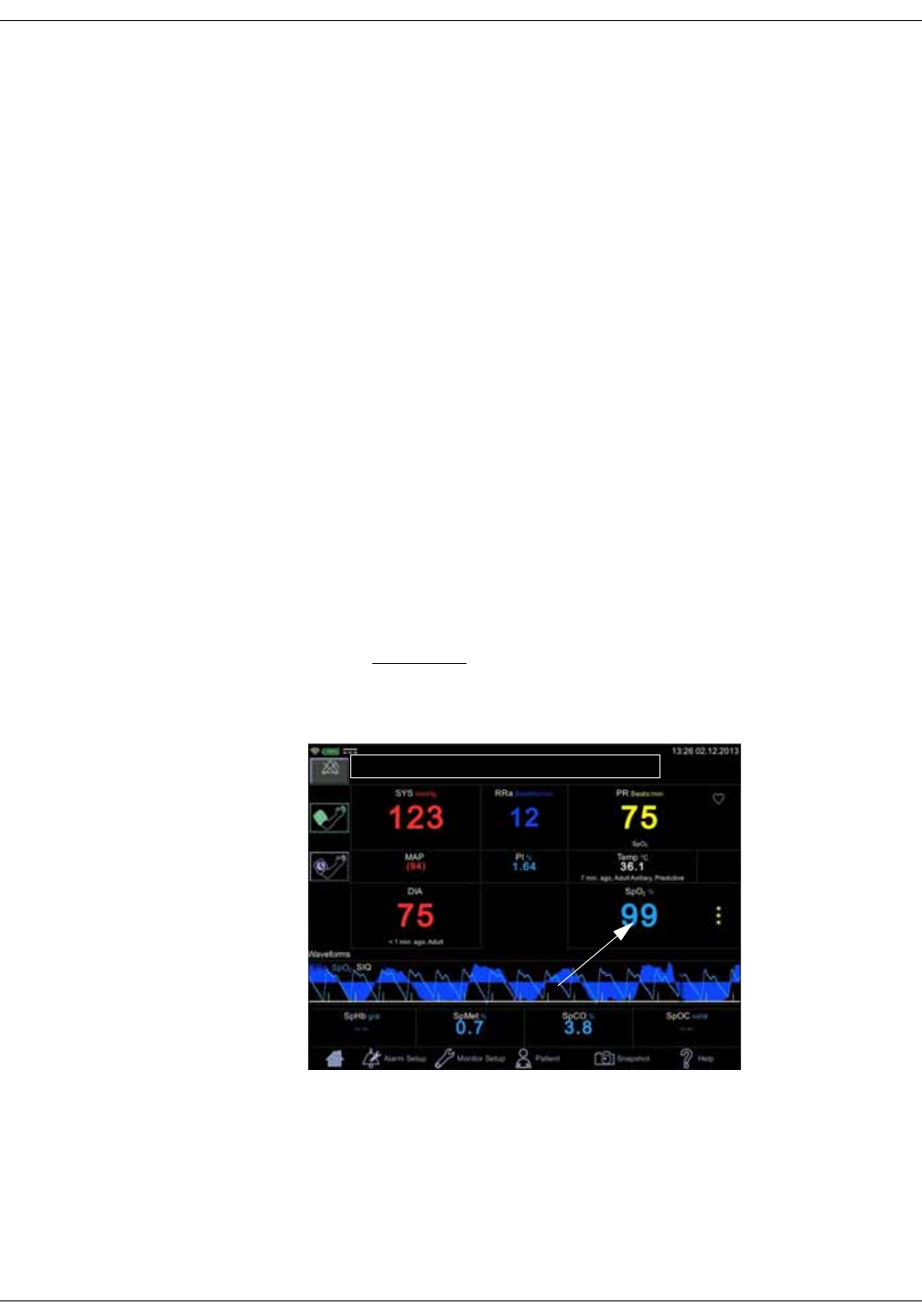
8-2 VC150 Vital Signs Monitor KO00065K
Masimo SpO2: Description
Description
The SpO2 parameter in the monitor is available in three different technologies:
• GE TruSignal
• Nellcor OxiMaxTM
• Masimo rainbow® SET®
The SpO2 technology logo on the left side of the monitor, above the physical
connector, will disclose which technology the monitor is equipped with. If you
want to use a different SpO2 technology than your monitor is currently equipped
with, contact service to discuss the procedure. Use of Masimo rainbow® SET®
parameters or Masimo RRa requires licenses that can be purchased separately
and may need specific accessories.
The SpO2 function is calibrated to read functional arterial oxygen saturation.
When a suitable SpO2 sensor is connected to the monitor and to the patient, the
measurement values will be shown on the screen. Pulse rate derived from SpO2
appears in the PR (Pulse Rate) window and updates continuously. The primary
source of pulse rate is always SpO2, i.e., if SpO2 is measuring when an NIBP
determination is completed, the pulse rate derived from NIBP is not displayed. A
tone sounds at a rate corresponding to the pulse rate and at a pitch
corresponding to the SpO2 saturation level. The pitch is highest at 100% oxygen
saturation, and it continuously decreases as the saturation level falls.
CAUTION
The pulse rate derived from SpO2 is a value calculated from oxygen
levels. The pulse rate is not equal to the patient’s actual heart rate.
Audible and visual alarms occur when SpO2 levels are outside the alarm limits.
and the monitor is in monitoring mode. When a parameter status alarm occurs,
an alarm message appears at the top of the screen (rectangle in the image
above).

KO00065K VC150 Vital Signs Monitor 8-3
Masimo SpO2: Description
SpO2 safety
WARNINGS
Many factors may cause inaccurate readings and alarms, decreased
perfusion, and/or low signal strength:
Interfering substances:
- Carboxyhemoglobin may erroneously increase SpO2 readings.
- Methemoglobin (MetHb) usually represents less than 1% of the total
Hgb, but in the case of methemoglobinemia that can be congenital or
induced by some IV dyes, antibiotics (such as sulphas), inhaled gases,
etc., this level increases sharply. Methemoglobin may cause inaccurate
SpO2 readings.
- Intravascular dyes (such as indocyanine green, methylene blue, etc.) at
certain concentrations may cause inaccurate SpO2 readings and/or
decreased perfusion and corresponding signal strength, potentially
causing inaccurate SpO2 readings.
-Nail polish and artificial nails may cause inaccurate readings.
Physiological characteristics:
Some physiological characteristics may cause decreased perfusion
and/or low signal strength and may potentially cause inaccurate SpO2
readings:
- Cardiac arrest, hypotension, shock, severe vasoconstriction, severe
anemia, hypothermia, venous pulsations, congestions, darkly
pigmented skin, ventricular septal defects (VSDs)
Environmental conditions:
Some environmental conditions may cause interference or artifact and
may potentially cause inaccurate SpO2 readings.
- Excessive ambient light sources (e.g., infrared heat lamps, strobe
lights, bilirubin lights, direct sunlight, operating room lights). To prevent
such interference, cover the sensor with opaque material.
- Electrical interference/Electrosurgery
- Defibrillation - May cause inaccurate reading for a short amount of
time.
- Excessive patient/sensor motion. Artifact can simulate an SpO2
reading, so that the monitor fails to sound an alarm. In order to ensure
reliable patient monitoring, the proper application of the probe and the
signal quality must be checked at regular intervals.
Sensor placement:
- Sensor placement on the same extremity as a blood pressure cuff,
arterial catheter or intravascular line; or arterial occlusion proximal to
the sensor; or a sensor below the heart level may cause decreased
perfusion and/or low signal strength and potentially cause inaccurate
SpO2 readings.
- Poor sensor fit may cause decreased or low signal strength and
potentially cause inaccurate SpO2 readings.
- Do not allow tape to block the sensor light emitter and detector as this
may cause decreased perfusion and/or low signal strength and
potentially cause inaccurate SpO2 readings.
- Before using the Masimo sensor, carefully read the Masimo sensor
instructions for use.

8-4 VC150 Vital Signs Monitor KO00065K
Masimo SpO2: Description
WARNING
As with any wrap or clip-on sensor, pressure is exerted. Be cautious in
using a wrap or clip-on sensor on patients with compromised
circulation (e.g., peripheral vascular disease or vasoconstricting
medications).
Allow sensor and cable to dry completely after cleaning. Moisture and
dirt on the connector can affect the measurement accuracy.
Inaccurate SpO2 data can result if a sensor is past its useful life.
Therefore, re-evaluate the measurement periodically by performing
additional assessment of the patient equipment, including
consideration of use of alternate monitoring methods such as direct
measurement of arterial oxyhemoglobin saturation (SaO2).
If the accuracy of any measurement does not seem reasonable, first
check the patient’s vital signs, then check for conditions that may cause
inaccurate SpO2 readings. If the problem is still not resolved, check the
SpO2 module or sensor for proper functioning.
Oximetry performance may be impaired when patient perfusion is low
or signal attenuation is high.
If the perfusion index falls below 0.02%, SpO2 values will not be
displayed.
A pulse oximeter or CO-oximeter should not be used as an apnea
monitor.
If you deactivate the SpO2 Sensor Off alarm, keep the patient under
close surveillance.
Single-use products are not designed to be reused. Reuse may cause a
risk of cross-contamination, affect the measurement accuracy and/or
system performance, and cause a malfunction as a result of the
product being physically damaged due to cleaning, disinfection, re-
sterilization and/or reuse.
Clean the surface of the probe before and after each patient use.
Do not loop the sensor cable into a tight coil or wrap around the device,
as this can damage the sensor cable.
CAUTION
Do not sterilize reusable sensors by irradiation, steam, or ethylene
oxide. See the sensor manufacturer's instructions for cleaning,
sterilization, or disinfecting methods.

KO00065K VC150 Vital Signs Monitor 8-5
Masimo SpO2: Description
CAUTIONS
Do not place SpO2 sensor on patient during magnetic resonance
imaging (MRI). Adverse reactions include potential burns to patients as a
result of contact with attachments heated by the MRI radio frequency
pulse, potential degradation of the magnetic resonance image, and
potential reduced accuracy of SpO2 measurements. Always remove
oximetry devices and attachments from the MRI environment before
scanning a patient.
Pulse oximetry readings and pulse signals can be affected by certain
environmental conditions, sensor application errors, and certain patient
conditions. See the appropriate sections of this manual for specific
safety information.
Placing a sensor distal to an arterial line may interfere with adequate
arterial pulsation and compromise the measurement of SpO2.
The sensor disconnect error message and associated alarm indicate
that the sensor is either disconnected or the wiring is faulty. The user
should check the sensor connection and, if necessary, replace the
sensor, interconnect cable, or both.
Placing a sensor on a polished or an artificial nail may affect accuracy.
Patient safety:
Do not place any clip-on sensor in a patient’s mouth, on their nose or
toes, on their thumb, or across a child’s foot or hand.
Prolonged monitoring or incorrect sensor application can cause skin
irritation or impaired circulation. Observe the sensor site frequently to
assure adequate distal circulation. Sensor sites should be checked at
least every 2 hours and rotated at least every 4 hours. Refer to
instructions supplied with sensor.
If the sensor is not applied properly, the patient’s skin could be injured or
the ability of the monitor to measure oxygen saturation could be
compromised. For example, a clip-on sensor should never be taped
shut. Taping the sensor could damage the patient’s skin or impair the
venous return, thus causing venous pulsation and inaccurate
measurement of oxygen saturation.
Excessive pressure from the sensor may cause necrosis of the skin.
Monitor performance:
Place the sensor so that the LEDs and the photodiode are opposite each
other.
Monitor performance:
When an SpO2 sensor is located on the same limb as the NIBP cuff, SpO2
readings will not be valid while the cuff is inflated. If valid SpO2 readings
are required during the entire blood pressure determination, attach the
SpO2 sensor to the limb opposite the one with the blood pressure cuff.

8-6 VC150 Vital Signs Monitor KO00065K
Masimo SpO2: SpO2 on the screen
NOTES
• A patient’s vital signs may vary dramatically during the use of
cardiovascular agents such as those that raise or lower blood pressure or
those that increase or decrease pulse rate.
•SpO
2 and pulse rate values are filtered by an averaging technique, which
determines how quickly the reported values respond to changes in the
patient’s saturation. Increased averaging time effects time to alarm for SpO2
saturation and pulse rate limits.
• Pulse rate measurement is based on the optical detection of a peripheral
flow pulse and therefore may not detect certain arrhythmias. The pulse
oximeter should not be used as a replacement or substitute for ECG based
arrhythmia analysis.
• Software development, software validation, and risk and hazard analysis
have been performed to a registered quality system.
• A functional tester cannot be used to assess the accuracy of a pulse
oximeter probe or a pulse oximeter monitor.
• The pulse oximeter cannot distinguish between oxyhemoglobin and
dyshemoglobins.
• Poor perfusion may affect the accuracy of measurement, especially when
using an ear sensor.
• Check that the red light is lit in the sensor.
• Check that the waveforms (if enabled in monitor setup) and parameter
values are displayed when the sensor is connected to the patient.
• Additional information specific to the Masimo sensors compatible with the
VC150, including information about parameter/measurement performance
during motion and low perfusion, may be found in the sensor's directions for
use (DFU).
SpO2 on the screen
When SpO2 is not receiving measurement data, a double dash (--) appears in this
window. When the sensor switches to operation mode, the SpO2 parameter
starts to receive data. If the data is valid, the derived SpO2 value appears in this
window and updates continuously. The values are displayed in %.
SpO2 values are displayed on the lower right
side of the monitor screen. The SpO2 and PI
values are displayed in cyan color by
default. This can be changed in
configuration mode. If the monitor is
providing the temperature measurement
the SpO2 value will be located under the
displayed temperature value.
The SpO2 field consists of the SpO2 label, the
measured value in the middle and the measurement site underneath the
parameter value. The measurement site choices are: Finger, Nose, Toe, Earlobe.
The site name Other can be used to indicate it was none of the above. The
default site is None. Next to the measured value is a column of asterisks
representing signal quality, as well as upper and lower limits for the SpO2 value.
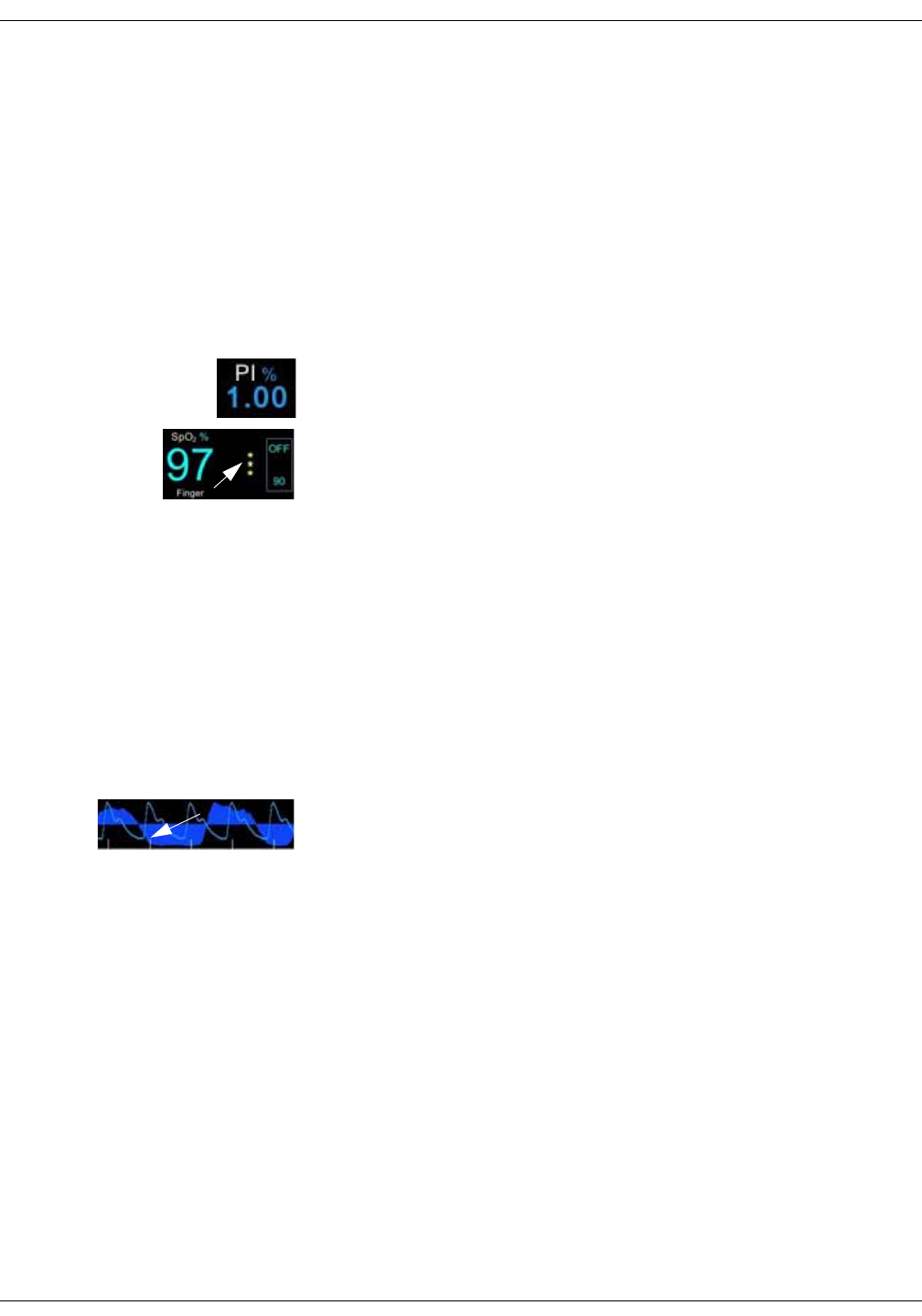
KO00065K VC150 Vital Signs Monitor 8-7
Masimo SpO2: SpO2 on the screen
If the sensor is detached from the patient, the SpO2 status switches to ‘off
patient’ and displays --.
NOTES
If pulse rate data from SpO2 data is available, the Pulse Rate window is
associated with this parameter and a heart symbol is displayed on screen.
Refer to “Pulse rate” on page 10-1 for more information.
If accuracy for a SpO2 derived parameter is not yet guaranteed, a dimmed
value is displayed on screen.
Perfusion index measurement
The perfusion index (PI) measurement is a clinical tool that provides a dynamic
numeric reflection of perfusion at the sensor site. PI is a relative value that varies
from patient to patient. The perfusion index value appears in its own field under
the label PI. The user can use the PI value to compare the strength of the pulse
signal at different sites on a patient in order to locate the best site for the sensor,
i.e., the site with the strongest pulse signal.
Signal quality values are mathematically calculated perfusion values
represented by asterisks.1 The SpO2 signal strength should be adequate. This is
indicated by the display of two or three asterisks or the absence of a Low Signal
Quality message. The more asterisks there are the better the signal quality. The
better the arterial blood flow is, the better signal quality is obtained. A strong
pulse signal increases the validity of SpO2 and pulse rate data.
1In Masimo equipped monitors signal quality is represented by asterisks, however signal quality is
not associated with the perfusion value. Refer to Signal IQ waveform (Masimo) section for further
information regarding Masimo signal quality representation.
Signal IQ (SIQ)
The Signal IQ provides an indicator of the assessment of the confidence in the
displayed SpO2 value. The SpO2 SIQ can be also used to identify the occurrence
of a patient's pulse.
With motion, the plethysmographic waveform is often distorted and may be
obscured by artifact. Shown as a vertical line, the SpO2 SIQ coincides with the
peak of an arterial pulsation. Even with a plethysmographic waveform obscured
by artifact, the Signal IQ identifies the timing that the algorithms have
determined for the arterial pulsation. The pulse tone (when enabled) coincides
with the vertical line of the SpO2 SIQ.
The height of the vertical line of the SpO2 SIQ provides an assessment of the
confidence in the measurement displayed. A high vertical bar indicates higher
confidence in the measurement. A small vertical bar indicates lower confidence
in the displayed measurement. When the Signal IQ is very low, this suggests that
the accuracy of the displayed measurement may be compromised.
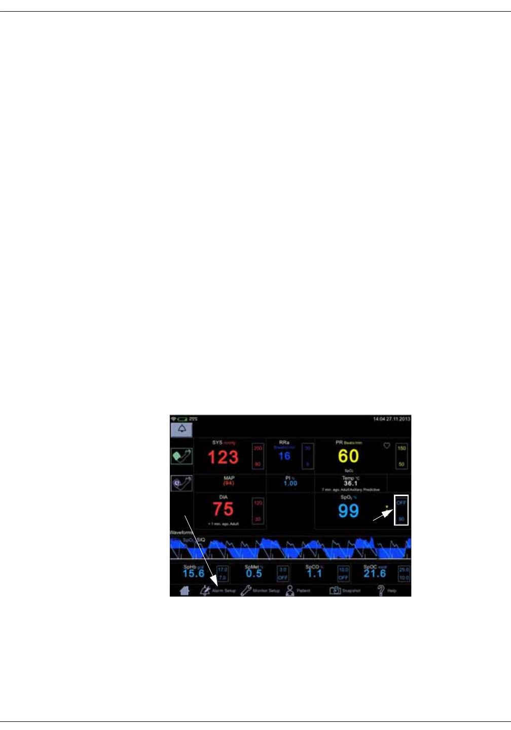
8-8 VC150 Vital Signs Monitor KO00065K
Masimo SpO2: SpO2 on the screen
When parameters are dimly lit, proceed with caution and do the following:
• Assess the patient.
• Check the sensor and ensure proper sensor application. The sensor must be
well secured to the site for the monitor to maintain accurate readings.
Misalignment of the sensor's emitter and detector can result in smaller
signals and cause erroneous readings.
• Determine if an extreme change in the patient's physiology and blood flow
at the monitoring site occurred, (e.g. an inflated blood pressure cuff, a
squeezing motion, sampling of an arterial blood specimen from the hand
containing the pulse oximetry sensor, severe hypotension, peripheral
vasoconstriction in response to hypothermia, medications, or an episode of
Raynaud's syndrome.)
• With neonates or infants, check that the peripheral blood flow to the sensor
site is not interrupted. Interruption, for example, may occur while lifting or
crossing their legs during a diaper change.
• After performing the above, if the parameter remains dimly lit frequently or
continuously, obtaining an arterial blood specimen for CO-Oximetry analysis
may be considered to verify the oxygen saturation value.
VC150 displays the signal quality also with 0 to 3 asterisks next to the SpO2
parameter.
Changing the SpO2 alarm limits
SpO2 alarm limit adjustments can be set either A) by entering upper and lower
limit values directly in a limit box on the home screen as instructed in “Using the
numeric keypad” on page 3-12 or B) by adjusting limit values in the Alarm Setup
screen as instructed in “Procedure for testing alarms” on page 3-11.
Pleth
The Plethysmographic waveform (Pleth) represents a real-time waveform for the
relative SpO2 pulsatile amplitude. The Pleth waveform is always automatically
scaled to fit the window for the best display quality. The waveform uses the
same color as the SpO2 field.
A
B
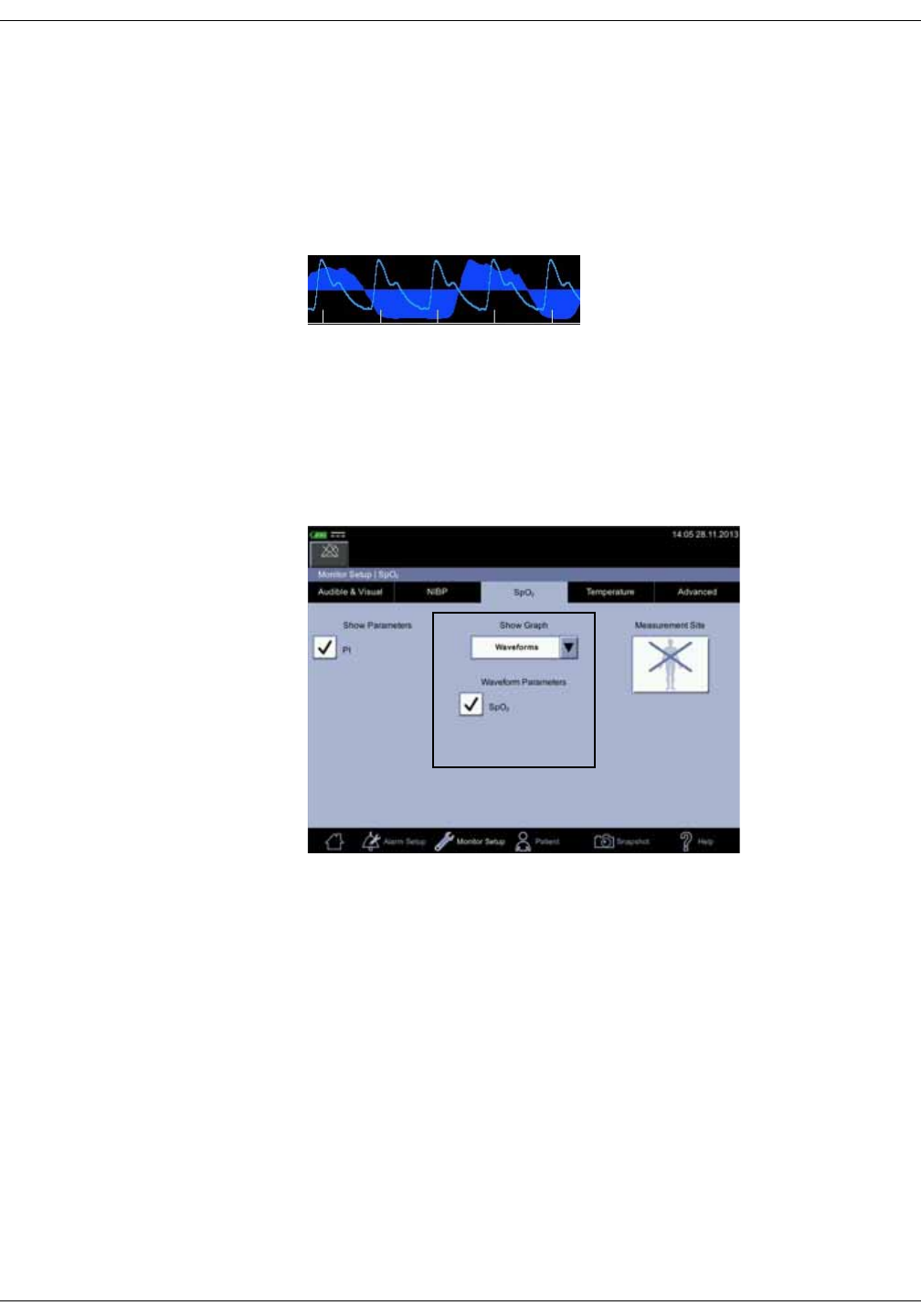
KO00065K VC150 Vital Signs Monitor 8-9
Masimo SpO2: SpO2 on the screen
Graphic representation of RRa (Masimo)
The RRa waveform data provides users with a visual indication of respiratory
activity. This requires an acoustic sensor. The RRa curve is slightly asymmetrical
as the airflow sounds generated in the upper airway are different during
different stages of breathing. Graphic representation can be selected in Monitor
Setup > SpO2. The RRa curve can be displayed simultaneously with the Pleth
curve.
Pleth waveform settings
Select Waveforms in the drop-down menu under Show Graph in the Monitor
Setup > SpO2 to display the Pleth. Also select parameters to be displayed as
waveforms (availability depends on which SpO2 technology the monitor is
equipped with and which options have been purchased).
SpO2 measurement site
For documentation purposes, you can select the measurement site for SpO2 in
Monitor Setup > SpO2 before you start measuring SpO2. A pop-up screen with
the following images will appear: Finger, Nose, Toe, Earlobe, Other or None. It
does not matter whether the site is on the left or right side of the patient. After
the site is selected, it will be displayed on the home screen in the SpO2
parameter window. The selection can be changed between the measurements.
Admitting a new patient will reset the selection of the measurement site.
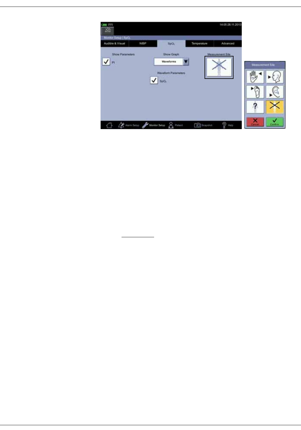
8-10 VC150 Vital Signs Monitor KO00065K
Masimo SpO2: SpO2 procedure
SpO2 procedure
1. Check the label on the monitor to determine which SpO2 technology the
monitor is using. To assure optimal performance, use only accessories that
are intended for that technology. If you cannot read the label, ask the nurse
manager or service which SpO2 technology is used.
2. Select a sensor that is appropriate for the patient, the clinical situation and
for the SpO2 technology used. Do not use an adult sensor on a neonatal/
pediatric patient and vice versa.
WARNING
Do not use a sensor, cables, or connectors that appear damaged or
with exposed electrical contacts.
Never repair a damaged sensor or cable; never use a sensor or cable
repaired by others.
3. Ensure the VC150 is connected to power or the battery is fully charged.
4. Ensure the VC150 is powered on. The monitor has to display clinical mode
and SpO2 parameter on screen.
5. Connect an interface cable to the monitoring system sensor port.
6. Follow the manufacturer’s guide to plug in the SpO2 cable into the monitor
and apply the proper SpO2 sensor. The VC150 reports the appropriate
sensor type in the message field when it detects the sensor. If you use RRa
sensor, place it as instructed in the direction of use of the sensor. Refer also
to “Acoustic Sensor placement” on page 8-11. If RRa sensor is used: contact
Innokas Medical service to upgrade the VC150 if the RRa parameter does
not appear on the screen.
7. Select the measurement site in Monitor Setup > SpO2, if desired. A shortcut:
Select SpO2 parameter area on the home screen to jump to the SpO2 screen.
8. Following the directions for use supplied with the sensor, apply the sensor to
the patient.

KO00065K VC150 Vital Signs Monitor 8-11
Masimo SpO2: SpO2 sounds
9. Proceed with monitoring. SpO2 measurements run continuously and can run
simultaneously with other measurements.
10. Clean the sensor as instructed in “Cleaning SpO2 sensors” on page B-8”.
SpO2 sounds
The monitor provides an audible tone for each pulse detected by the SpO2
parameter. The pitch of the audible tone is directly related to the calculated
saturation value. As the saturation value increases, the pitch rises. As the
saturation value decreases, the pitch frequency goes down. This audible tone is
silenced while an alarm sounds or the Day Volume or Night Volume is set to 0.
Refer to “Audible & Visual” on page 3-19 in this section.
Acoustic sensors
Masimo SpO2 technology uses acoustic sensors to capture breathing sounds
that are relayed to the monitor and transformed into a respiration rate. A Dual
rainbow® cable with two sensors at the end of the cable is connected to the
monitor. Then place the RRa sensor over the patient’s airway on either side of
their neck and the other on some part of the body for SpO2 measurement.
Respiration rate is provided only if SpO2 data is also measured.
Acoustic Sensor placement
The Acoustic sensor has a small black arrow on the front (item 1 in figure below),
when placing the sensor the black arrow should point forward to the anterior of
subject’s body.
1. Ensure placement site is hair-free, clean of debris, and dry prior to sensor
placement. Use an alcohol swab to clean the neck area, if needed.
2. The sensor pad (item 2 in the figure above) should be placed to either side of
the larynx, in the area just above the thyroid cartilage and below the jaw line
(see figure below). Ensure that there are no skin folds under the sensor pad.
1
2
3

8-12 VC150 Vital Signs Monitor KO00065K
Masimo SpO2: SpO2 sounds
NOTE
For pediatric subjects that have limited neck space, the sensor may be
placed on the right side of chest (dotted oval in the image above),
underneath clavicle. The sensor should not be touching the clavicle.
3. Place sensor tape on skin.
4. Gently press on sensor tape from center outward so adhesive forms a good
contact with patient's skin.
5. Ensure there are no skin folds or air gaps under sensor pad.
6. Remove the release liner from the anchor pad and place the anchor pad on
patient’s side of the neck; route the sensor cable in front of patient. Do not
place anchor pad on clothing.

KO00065K VC150 Vital Signs Monitor 8-13
Masimo SpO2: Alarms
Alarms
If the SpO2 parameter determines the signal to be valid, SpO2 values are
displayed. In case the signal quality deteriorates to a questionable level, the
SpO2 or Pulse Rate values disappear from the screen and an alarm message for
lost pulse signal is generated.
Alarm timer
The user can select between monitoring mode and spot-check mode. In spot-
check mode, clinical alarms and related functions are not available. If an SpO2
measurement continues for 5 minutes uninterrupted, the monitor automatically
moves from spot-check mode to monitoring mode. The alarms will be enabled in
monitoring mode.
If the probe is taken off and you want to measure the same patient without
alarms, select spot-check mode again.
NOTE
To prevent misuse of the device, duration of the SpO2 spot-check mode is
limited to 5 minutes.
If SpO2 is unable to be measured for some reason, then a technical status
message that indicates the reason for not measuring will appear below the
parameter value. If an abnormal technical status remains for ten seconds, then
a low priority alarm is created.
An abnormal technical status will create an alarm in both spot-check and
monitoring mode.
Compatible Masimo accessories
All approved and VC150 compliant accessories are listed in the VC150 supplies
and accessories document. Use only accessories listed in that document. If you
already have an accessory that you want to use with the VC150 monitor, check
whether it is listed in that document. If it not listed, do not use it with the VC150
monitor.
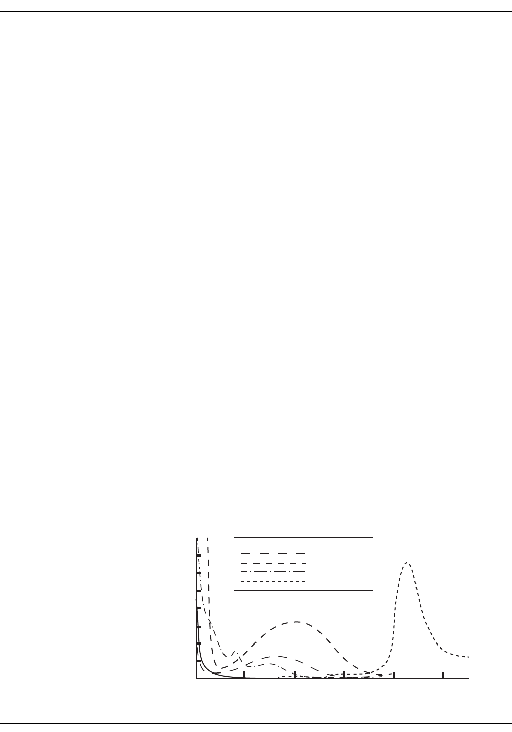
8-14 VC150 Vital Signs Monitor KO00065K
Masimo SpO2: Masimo rainbow® SET® SpO2 and special features
Masimo rainbow® SET® SpO2 and special features
Masimo Signal Extraction Technology (SET) pulse oximetry utilizes parallel
engines and adaptive digital filtering. The Masimo SET signal processing
algorithm, Discrete Saturation Transform® (DST®), in parallel with Fast Saturation
Transform (FST®), identifies the noise, isolates it and, using adaptive filters,
cancels it. It then reports the true arterial oxygen saturation for display on the
monitor.
Functional oxygen saturation (SpO2) of arterial blood is noninvasively and
continuously monitored using pulse oximetry technology from Masimo
rainbow® SET®. Functional SpO2 is the ratio of oxygenated hemoglobin to
hemoglobin that is capable of transporting oxygen. This ratio, expressed as a
percentage, is shown in the SpO2 window, which is continually updated. If the
signal quality is low for any Masimo parameter, the corresponding
measurement value is dimmed. This is typical when the sensor is connected to a
patient and a new measurement begins. As the signal quality is determined to
be reliable, the values turn to normal brightness.
The SpO2 parameter is indicated for use in continuous, noninvasive monitoring
of functional oxygen saturation and in providing pulse rate data as a component
of the monitor. This device is not designed, sold, or intended for use except as
indicated.
rainbow Pulse CO-Oximetry Technology
rainbow Pulse CO-Oximetry technology is governed by the following principles:
1. Oxyhemoglobin (oxygenated blood), deoxyhemoglobin (non-oxygenated
blood), carboxyhemoglobin (blood with carbon monoxide content),
methemoglobin (blood with oxidized hemoglobin) and blood plasma
constituents differ in their absorption of visible and infrared light (using
spectrophotometry).
2. The amount of arterial blood in tissue changes with pulse
(photoplethysmography). Therefore, the amount of light absorbed by the
varying quantities of arterial blood changes as well.
600 800 1000 1200 1400 1600
Wavelength (nm)
Carboxyhemoglobin
Oxyhemoglobin
Methemoglobin
Absorption (l/mm)
4.0
3.5
3.0
2.5
2.0
1.5
1.0
0.5
0
Deoxyhemoglobin
Plasma
Absorption Spectra

KO00065K VC150 Vital Signs Monitor 8-15
Masimo SpO2: Masimo rainbow® SET® SpO2 and special features
Masimo rainbow sensors use a multi-wavelength sensor to distinguish between
oxygenated blood, deoxygenated blood, blood with carbon monoxide, oxidized
blood and blood plasma.
Masimo rainbow sensors utilize various light-emitting diodes (LEDs) that pass
light through the site to a diode (detector). Signal data is obtained by passing
various visible and infrared lights (LEDs, 500 to 1400nm) through a capillary bed
(for example, a fingertip, a hand, a foot) and measuring changes in light
absorption during the blood pulsatile cycle. This information may be useful to
clinicians. The maximum radiant power of the strongest light is rated at 25
mW. The detector receives the light, converts it into an electronic signal and
sends it to the Masimo circuit board for calculation.
Once the Masimo board receives the signal from the sensor, it utilizes
proprietary algorithms to calculate the patient’s functional oxygen saturation
(SpO2 [%]), blood levels of carboxyhemoglobin (SpCO [%]), methemoglobin
(SpMet [%]), total hemoglobin concentration (SpHb [g/dL]) and pulse rate (PR).
The SpCO, SpMet and SpHb measurements rely on a multi-wavelength
calibration equation to quantify the percentage of carbon monoxide and
methemoglobin and the concentration of total hemoglobin in arterial blood.
In an ambient temperature of 35° C the maximum skin surface temperature has
been measured at less than 106° F (41° C), verified by Masimo sensor skin
temperature test procedure.
Pulse CO-Oximetry vs. Drawn Whole Blood Measurements
When SpO2, SpCO, SpMet, and SpHb measurements obtained by Masimo
rainbow technology (noninvasive) are compared to drawn whole blood (invasive)
measurements by blood gas and/or laboratory CO-Oximetry methods, caution
should be taken when evaluating and interpreting the results.
The blood gas and/or laboratory CO-Oximetry measurements may differ from
the SpO2, SpCO, SpMet, SpHb, and SpOC measurements made by Masimo
rainbow technology. Any comparisons should be simultaneous, meaning the
measurement on the device should be noted at the exact time that blood is
drawn.
1. Light Emitting Diodes (LEDs)
(7 or more wavelengths)
2. Detector
1
2

8-16 VC150 Vital Signs Monitor KO00065K
Masimo SpO2: Masimo rainbow® SET® SpO2 and special features
In the case of SpO2, different results are usually obtained from the arterial blood
gas sample if the calculated measurement is not appropriately corrected for the
effects of variables that shift the relationship between the partial pressure of
oxygen (PO2) and saturation, such as: pH,temperature, the partial pressure of
carbon dioxide (PCO2), 2,3-DPG, and fetal hemoglobin. In the case of SpCO,
different results are also expected if concentration of methemoglobin in the
blood gas sample is abnormal (greater than 2% for methemoglobin
concentration).
High levels of bilirubin may cause erroneous SpO2, SpMet, SpCO, and SpHb
readings. As blood samples are usually taken over a period of 20 seconds (the
time it takes to draw the blood) a meaningful comparison can only be achieved if
the oxygen saturation, carboxyhemoglobin, and methemoglobin concentration
of the patient are stable and not changing over the period of time that the blood
gas sample is taken. Subsequently, blood gas and laboratory CO-Oximetry
measurements of SpO2, SpCO, SpMet, SpHb, and SpOC may vary with the rapid
administration of fluids and in procedures such as dialysis. Additionally, drawn
whole blood testing can be affected by sample handling methods and time
elapsed between blood draw and sample testing.
Measurements with Low Signal IQ should not be compared to laboratory
measurements.
General Description for Total Arterial Oxygen Content (CaO2)
Oxygen (O2) is carried in the blood in two forms, either dissolved in plasma or
combined with hemoglobin. The amount of oxygen in the arterial blood is
termed the oxygen content (CaO2) and is measured in units of ml O2/dL blood.
One gram of hemoglobin (Hb) can carry 1.34 ml of oxygen, whereas 100 ml of
blood plasma may carry approximately 0.3 ml of oxygen*. The oxygen content is
determined mathematically as:
CaO2 = 1.34 (ml O2/g Hb) x Hb (g/dL) x HbO2 + PaO2 (mm Hg) x (0.3 ml O2/100
mm Hg/dL)
Where HbO2 is the fractional arterial oxygen saturation and PaO2 is the partial
pressure of arterial oxygen.
For typical PaO2 values, the second part of the above equation (PaO2 [mm Hg] x
[0.3 ml O2/ 100 mm Hg/dL]) is approximately 0.3 ml/dL. Furthermore, for typical
carboxyhemoglobin and methemoglobin levels, the functional saturation (SpO2)
as measured by a pulse oximeter is given by:
SpO2 = 1.02 x HbO2
*Martin, Laurence. All You Really Need to Know to Interpret Arterial Blood Gases,
Second Edition. New York: Lippincott Williams & Wilkins, 1999.

KO00065K VC150 Vital Signs Monitor 8-17
Masimo SpO2: Masimo rainbow® SET® SpO2 and special features
General Description for SpOC
The above approximations result in the following reduced equation for oxygen
content via the Pulse CO-Oximeter:
SpOC (ml/dL*) = 1.31 (ml O2/g Hb) x SpHb (g/dL) x SpO2 + 0.3 ml/dL
*When ml O2/g Hb is multiplied by g/dL of SpHb, the gram unit in the
denominator of ml/g cancels the gram unit in the numerator of g/dL resulting in
ml/dL (ml of oxygen in one dL of blood) as the unit of measure for SpOC.
Description for Carboxyhemoglobin (SpCO)
Pulse CO-Oximetry is a continuous and noninvasive method of measuring the
levels of carboxyhemoglobin concentration (SpCO) in arterial blood. It relies on
the same basic principles of pulse oximetry (spectrophotometry) to make its
SpCO measurement.
The measurement is obtained by placing a sensor on a patient, usually on the
fingertip for adults and the hand or foot for infants. The sensor connects either
directly to the Pulse CO-Oximetry instrument or through an instrument patient
cable.
The sensor collects signal data from the patient and sends it to the instrument.
The instrument displays the calculated data as percentage value for the SpCO,
which reflect blood levels of carbon monoxide bound to hemoglobin.
Successful Monitoring for SpCO
A stable SpCO reading is associated with correct sensor placement, small
physiological changes during the measurement and acceptable levels of arterial
perfusion in the patient’s fingertip (measurement site). Physiological changes at
the measurement site are mainly caused by fluctuations in the oxygen
saturation, blood concentration and perfusion.
General Description for Total Hemoglobin (SpHb)
Pulse CO-Oximetry is a continuous and noninvasive method of measuring the
levels of total hemoglobin (SpHb) in arterial blood. It relies on the same principles
of pulse oximetry to make its SpHb measurement. The measurement is taken by
a sensor capable of measuring SpHb, usually on the fingertip for adult and
pediatric patients.
The sensor connects directly to the Pulse CO-Oximeter or with a patient cable.
The sensor collects signal data from the patient and sends it to the instrument.
The instrument displays the calculated data as measurement of total
hemoglobin concentration.

8-18 VC150 Vital Signs Monitor KO00065K
Masimo SpO2: Masimo rainbow® SET® SpO2 and special features
Successful Monitoring for SpHb
A stable SpHb reading is associated with correct sensor placement, small
physiological changes during the measurement and acceptable levels of arterial
perfusion at the measurement site. Physiological changes at the measurement
site are mainly caused by fluctuations in the oxygen saturation, blood
concentration and perfusion.
General Description for Methemoglobin (SpMet)
Pulse CO-Oximetry is a continuous and noninvasive method of measuring the
levels of methemoglobin concentration (SpMet) in arterial blood. It relies on the
same basic principles of pulse oximetry (spectrophotometry) to make its SpMet
measurement.
The measurement is obtained by placing a sensor on a patient, usually on the
fingertip for adults and the hand or foot for infants. The sensor connects either
directly to the Pulse CO-Oximetry instrument or through a patient cable.
The sensor collects signal data from the patient and sends it to the instrument.
The instrument displays the calculated data as percentage value for the SpMet.
Successful Monitoring for SpMet
A stable SpMet reading is associated with correct sensor placement, small
physiological changes during the measurement and acceptable levels of arterial
perfusion in the patient’s fingertip (measurement site).
Physiological changes at the measurement site are mainly caused by
fluctuations in the oxygen saturation, blood concentration and perfusion.
WARNINGS
Masimo labeled monitors are compatible only with Masimo sensors and
cables, which are available from your Innokas Medical representative or
from Masimo or its local representative. Other oxygen transducers
(sensors) may cause improper SpO2 performance.
Pulse rate measurement is based on the optical detection of a
peripheral flow pulse and therefore may not detect certain arrhythmias.
The pulse oximeter should not be used as a replacement or substitute
for ECG-based arrhythmia analysis.
A pulse CO-oximeter should be considered an early warning device. As a
trend towards patient hypoxemia is indicated, blood samples should be
analyzed by laboratory instruments to completely understand the
patient’s condition.
For measurements of high or low SpHb readings, blood samples should
be analyzed by laboratory instruments to completely understand the
patient’s condition.

KO00065K VC150 Vital Signs Monitor 8-19
Masimo SpO2: Masimo rainbow® SET® SpO2 and special features
WARNINGS
SpO2 is empirically calibrated to functional arterial oxygen saturation in
healthy adult volunteers with normal levels of carboxyhemoglobin
(COHb) and methemoglobin (MetHb). A pulse oximeter cannot measure
elevated levels of COHb or MetHb. Increases in either COHb or MetHb
will affect the accuracy of the SpO2 measurement.
For increased COHb: COHb levels above normal tend to increase
the level of SpO2. The level of increase is approximately equal to the
amount of COHb that is present.
NOTE! High levels of SpCO may occur with a seemingly normal
SpO2. When elevated levels of SpCO are suspected, laboratory
analysis (CO-oximetry) of a blood sample should be performed.
For increased MetHb: the SpO2 may be decreased by levels of MetHb of
up to approximately 10% to 15%. At higher levels of MetHb, the SpO2
may tend to read in the low to mid 80s. When elevated levels of MetHb
are suspected, laboratory analysis (CO-oximetry of a blood sample
should be performed.
Interfering substances: Dyes, or any substance containing dyes, that
change usual blood pigmentation may cause erroneous readings.
Hemoglobin synthesis disorders may cause erroneous SpHb readings.
Elevated levels of total bilirubin may lead to inaccurate SpO2, SpMet,
SpCO, SpHb, and SpOC measurements.
Motion artifact may lead to inaccurate SpMet, SpCO, SpHb, SpOC
measurements.
Severe anemia may cause erroneous SpO2 readings.
Very low arterial oxygen saturation (SpO2) levels may cause inaccurate
SpCO and SpMet measurements.
With very low perfusion at the monitored site, readings may read lower
than core arterial oxygen saturation.
Do not use tape to secure the sensor to the site; this can restrict blood
flow and cause inaccurate readings. Use of additional tape can cause
skin damage or damage the sensor.
If the sensor is wrapped too tightly or supplemental tape is used,
venous congestion/pulsations may occur, causing erroneous readings.
Venous congestion may cause under reading of actual arterial oxygen
saturation. Therefore, assure proper venous outflow from the monitored
site. Sensor should not be below heart level (e.g. sensor on hand of a
patient in bed with arm dangling to the floor).
Venous pulsations may cause erroneous readings (e.g. tricuspid valve
regurgitation).

8-20 VC150 Vital Signs Monitor KO00065K
Masimo SpO2: Masimo rainbow® SET® SpO2 and special features
WARNINGS
Loss of pulse signal can occur when:
• Sensor is too tight.
• The patient has hypotension, severe vasoconstriction, severe
anemia, or hypothermia.
• There is arterial occlusion proximal to the sensor.
• The patient is in cardiac arrest or is in shock.
The pulsations from intra-aortic balloon support can be additive to the
pulse rate on the oximeter pulse rate display. Verify patient’s pulse rate
against the ECG heart rate.
Misapplied sensors or sensors that become partially dislodged may
cause either over or under reading of actual arterial oxygen saturation.
Avoid placing the sensor on any extremity with arterial catheter or
blood pressure cuff.
High intensity extreme lights (including pulsating strobe lights) directed
on the sensor may not allow the pulse CO-oximeter to obtain readings.
The pulse CO-oximeter can be used during defibrillation, but the
readings may be inaccurate for up to 20 seconds.
Before use, carefully read the sensor’s directions for use.
Tissue damage can be caused by incorrect application or use of a
sensor, for example by wrapping the sensor too tightly. Inspect the
sensor site as directed in the sensor’s directions for use to ensure skin
integrity and correct positioning and adhesion of the sensor.
To avoid cross contamination only use Masimo single use sensors on
the same patient.
Unless otherwise specified, do not sterilize sensors or patient cables by
irradiation, steam, autoclave or ethylene oxide. See the cleaning
instructions in the directions for use for the Masimo re-useable sensors.
SpO2 monitoring is required when monitoring RRa (acoustic respiration).
Excessive ambient noise may affect the accuracy of the respiration rate
reading from the acoustic respiration sensor.
Do not attempt to reprocess, recondition or recycle any Masimo sensors
or patient cables as these processes may damage the electrical
components, potentially leading to harm.
For SpHb, the VC150 should be considered an early warning device.
Blood samples should be analyzed by laboratory instruments prior to
clinical decision making to completely understand the patient’s
condition.

KO00065K VC150 Vital Signs Monitor 8-21
Masimo SpO2: Masimo rainbow® SET® SpO2 and special features
WARNINGS
Variation in hemoglobin measurements may be profound and may be
affected by sample type, body positioning, as well as other physiological
conditions. As with most hemoglobin tests, VC150 test results should be
scrutinized in light of a specific patient’s condition. Any results
exhibiting inconsistency with the patient’s clinical status should be
repeated and/or supplemented with additional test data.
Inaccurate SpHb and SpOC readings may be caused by:
• Intravascular dyes such as indocyanine green or methylene blue
• Externally applied coloring and texture such as nail polish, acrylic
nails, glitter, etc.
• Elevated levels of bilirubin
• Low arterial perfusion
•Motion artifact
• Low arterial oxygen saturation levels
• Elevated carboxyhemoglobin levels
• Elevated methemoglobin levels
• Difference between patient's finger skin and finger core
temperature
• Hemoglobin synthesis disorders
• Hemoglobinopathies and synthesis disorders such as thalassemias,
Hb s, Hb c, sickle cell, etc.
• Vasospastic disease such as Raynaud's
• Elevated altitude
• Peripheral vascular disease
• Liver disease
• EMI radiation interference
Inaccurate SpCO and SpMet readings may be caused by:
• Intravascular dyes such as indocyanine green or methylene blue
• Abnormal hemoglobin levels
• Low arterial perfusion
• Low arterial oxygen saturation levels including altitude induced
hypoxemia
• Elevated total bilirubin levels
•Motion artifact
• SpCO readings may not be provided if SpO2 readings are less than
90%
• SpCO readings may not be provided if SpMet readings are greater
than 2%

8-22 VC150 Vital Signs Monitor KO00065K
Masimo SpO2: Masimo rainbow® SET® SpO2 and special features
WARNING
Inaccurate SpCO readings can be caused by:
• Levels of methemoglobin approximately 1.5% or above
Inaccurate respiration rate measurements may be caused by:
• Low arterial perfusion
•Motion artifact
• Low arterial oxygen saturation
• Excessive ambient or environmental noise
• Improper sensor placement
The Desat Index alarm is intended as an adjunct rather than in place of
the Low Saturation alarm.
CAUTIONS
Do not use the pulse CO-oximeter or oximetry sensors during magnetic
resonance imaging (MRI) scanning. Induced current could potentially
cause burns. The pulse CO-oximeter may affect the MRI image, and the
MRI unit may affect the accuracy of the oximetry measurements.
If using pulse CO-oximetry during full body irradiation, keep the sensor
out of the irradiation field. If the sensor is exposed to the radiation, the
reading might be inaccurate or the unit might read zero for the duration
of the active irradiation period.
Exercise caution when applying a sensor to a site with compromised
skin integrity. Applying tape or pressure to such a site may reduce
circulation and/or cause further skin deterioration.
Circulation distal to the sensor site should be checked routinely.
A functional tester cannot be utilized to assess the accuracy of the
pulse CO-oximeter or any sensors.
Do not modify or alter the sensor in any way. Alterations or modification
may affect performance and/or accuracy.
The dual rainbow® cable is designed to directly interface with validated
rainbow® acoustic monitoring enabled devices or with validated
rainbow® acoustic monitoring enabled multiparameter monitors.
CAUTIONS
Failure to properly connect a dual rainbow® cable to the rainbow®
acoustic monitoring enabled device or multiparameter monitor may
result in intermittent readings, inaccurate results or no reading.
If the SpO2 Perfusion Low message is frequently displayed, find a better
perfused monitoring site. In the interim, assess the patient and, if
indicated, verify oxygenation status through other means.

KO00065K VC150 Vital Signs Monitor 8-23
Masimo SpO2: Masimo rainbow® SET® SpO2 and special features
rainbow Acoustic Monitoring (RAM) Technology
rainbow Acoustic Monitoring (RAM) continuously measures a patient’s
respiration rate based on airflow sounds generated in the upper airway. The
Acoustic Sensor translates airflow sounds generated in the upper airway to an
electrical signal that can be processed to produce a respiration rate, measured
as breaths per minute.
Respiratory sounds include sounds related to respiration such as breath sounds
(during inspiration and expiration), adventitious sounds, cough sounds, snoring
sounds, sneezing sounds, and sounds from the respiratory muscles [1].
These respiratory sounds often have different characteristics depending on the
location of recording [2] and they originate in the large airways where air
velocity and air turbulence induce vibration in the airway wall. These vibrations
are transmitted, for example, through the lung tissue, thoracic wall and trachea
to the surface where they may be heard with the aid of a stethoscope, a
stethoscope, a microphone or more sophisticated devices.
rainbow Acoustic Monitoring Architecture
The following figure illustrates how a respiratory sound produced by a patient
can be turned into a numerical measurement that corresponds to a respiratory
parameter.
Patient
The generation of respiratory sounds is primarily related to turbulent respiratory
airflow in upper airways. Sound pressure waves within the airway gas and
airway wall motion contribute to the vibrations that reach the body surface and
are recorded as respiratory sounds.
Although the spectral shape of respiratory sounds varies widely from person to
person, it is often reproducible within the same person, likely reflecting the
strong influence of individual airway anatomy [2-6].
Patient
Signal
Sensor
Envelope
Acquisition
RRa Estimation
System
Processing
Respiratory airflow
to sound
Sound to electrical
signal
Electrical signal to
digital signal
Digital signal to
respiratory
measurement
Detection

8-24 VC150 Vital Signs Monitor KO00065K
Masimo SpO2: Masimo rainbow® SET® SpO2 and special features
Sensor
The sensor captures respiratory sounds (and other biological sounds) much like
a microphone does. When subjected to a mechanical strain, (e.g., surface
vibrations generated during breathing), the sensor becomes electrically
polarized.
The degree of polarization is proportional to the applied strain. The output of the
sensor is an electric signal that includes a sound signal that is modulated by
inspiratory and expiratory phases of the respiratory cycle.
Acquisition System
The acquisition system converts the electric signal provided by the sensor into a
digital signal. This format allows the signal to be processed by a computing
device.
Signal Processing
The digital signal produced by the acquisition system is converted into a
measurement that corresponds to the respiratory parameter of interest. As
shown in the previous figure, this can be performed by, for example, determining
the digital signal envelope or outline which in turn may be utilized to determine
the respiratory rate. In this way, a real-time, continuous breath rate parameter
can be obtained and displayed on a monitor which, in many cases, may be real-
time and continuous.
The respiratory cycle envelope signal processing principle is similar to methods
that sample airway gasses and subsequently determine a respiratory rate.
[1] A.R.A. Sovijärvi, F. Dalmasso, J. Vanderschool, L.P. Malmberg, G. Righini, S.A.T.
Stoneman. Definition of terms for applications of respiratory sounds. Eur Respir
Rev 2000; 10:77, 597-610.
[2] Z. Moussavi. Fundamentals of respiratory sounds analysis. Synthesis lectures
on biomedical engineering #8. Morgan & Claypool Publishers, 2006.
[3] Olsen, et al. Mechanisms of lung sound generation. Semin Respir Med 1985; 6:
171-179.
[4] Pastercamp H, Kraman SS, Wodicka GR. Respiratory sounds – Advances
beyond the stethoscope. Am J Respir Crit Care Med 1977; 156: 974-987.
[5] Gavriely N, Cugell DW. Airflow effects on amplitude and spectral content of
normal breath sounds. J Appl Physiol 1996; 80: 5-13.
[6] Gavrieli N, Palti Y, Alroy G. Spectral characteristics of normal breath sounds. J
Appl Physiol 1981; 50: 307-314.

KO00065K VC150 Vital Signs Monitor 8-25
Masimo SpO2: Masimo rainbow® SET® SpO2 and special features
Masimo rainbow® SET® SpO2 configuration
There are multiple configuration settings associated with this parameter. Refer
to the following table for details and then configure as necessary.
Masimo rainbow® SET®
feature Description
Acoustic Resp Rate RRa This feature uses acoustic technology to continually measure a patient's respiration
rate based on airflow sounds generated during the breathing cycle of inspiration and
expiration.
Desat Index 3D Alarm This feature alerts for an increasing quantity of smaller desaturations that may not
exceed the low SpO2 alarm threshold and that may provide an early indication that
the patient's respiratory status is declining. The user enters the period of time over
which to look at desaturations, desired delta threshold (% from baseline), and number
of desaturations before being alerted.
Current number of desaturations is displayed by Desaturation Index. The number of
Desat Occurrences can be reset by 1) adjusting the Desat Threshold, or 2) removing
the sensor from the patient or the monitor.
Options:
•Desat Occurrences can range from 1 to 24.
•Desat Threshold range change from 2-10% in 1% increments.
•Desat Time period range from 1 to 4 hours in 1 hr increments.
Configure in Alarm Setup or Monitor Setup > Advanced > Default Setup > Alarm
Defaults.
FastSat Algorithm FastSat enables rapid tracking of arterial oxygen saturation changes. Arterial oxygen
saturation data is averaged using pulse oximeter averaging algorithms to smooth the
trend.
FastSat is always on when 2 - 4 and 4 - 6 averaging modes are activated.
FastSat is not recommended for routine use as the increased fidelity of this mode may
also increase the frequency of alarms caused by rapid but transitory changes in SpO2.
FastSat enables rapid response to, and display of, fast changes in SpO2 by giving
priority to the most recent data.
Oxygen Content SpOC During some seizures, oxygen levels may drop to dangerous levels. SpOC is a non-
invasive measure of the total oxygen content present in the blood.
Perfusion Index (PI) The Perfusion Index (PI) is the ratio of the pulsatile blood flow to the non-pulsatile or
static blood in peripheral tissue. PI thus represents a noninvasive measure of
peripheral perfusion that can be continuously and noninvasively obtained from a
pulse oximeter.

8-26 VC150 Vital Signs Monitor KO00065K
Masimo SpO2: Masimo rainbow® SET® SpO2 and special features
Perfusion Index Averaging This feature allows you to select the desired level of visibility to subtle variations in the
measured value. Depending on the patient acuity and area of care, shorter averaging
times are sometimes preferred (trauma) over longer averaging times (neonates) and
vice versa. This benefits patient care by fine tuning PI responsiveness to physiological
changes.
Options: Short, Long.
Configure in Monitor Setup > Advanced > Default Setup > Measurement Settings.
PI Delta 3D Alarm This feature alerts you to changes in perfusion. When enabled, the PI Delta alarm
notifies you if the patient's perfusion index (PI) declines by a user-selectable
percentage from the patient's baseline PI value over a user-selectable time period.
This alarm is intended to help you identify early changes in peripheral perfusion that
may otherwise be difficult to identify and are often missed despite being a potentially
valuable indicator of illness severity. The PI Delta Index baseline is continually being
calculated by the board while the sensor is on a patient.
NOTE
PI Delta 3D Alarm is a latching alarm that is not automatically dismissed when a
new patient is admitted. The alarm must always be acknowledged by selecting
the alarm message.
Options:
•PI Delta Range from 10% to 99% in 1% increments.
•PI Delta Time Period range from NONE, to 1, 5, and 30 min, plus 1, 4, 8, 12, 24, 36,
and 48 hours.
•Set Baseline PI to establish a level that PI Delta Index values are measured against.
Configure in Alarm Setup or Monitor Setup > Advanced > Default Setup > Alarm
Defaults.
Rapid Desat Alarm
Threshold This setting is intended to allow the clinician to feel comfortable setting longer alarm
delay periods - to minimize nuisance alarms for real but transitory events - by
overriding the alarm delay period when rapid desaturations exceed the alarm limit
threshold by a larger, user-selectable percentage.
This setting cannot be used with SpO2 alarm delay. The Rapid Desat Alarm Threshold
feature includes a built-in alarm delay for 15 seconds. For example, if Rapid Desat
Alarm Threshold is set at 5%, the SpO2 percentage can fall 5% below the lower limit
for less than 15 seconds. If the SpO2 percentage falls lower than 5% down from the
lower limit, an alarm will occur immediately. Also if SpO2 percentage remains 0.1-5%
down from the lower limit for over 15 seconds an alarm will occur immediately.
Options: 5%, 10%, Off.
Configure in Alarm Setup or Monitor Setup > Advanced > Default Setup > Alarm
Defaults.
Masimo rainbow® SET®
feature Description

KO00065K VC150 Vital Signs Monitor 8-27
Masimo SpO2: Masimo rainbow® SET® SpO2 and special features
RRa Alarm Delay Many changes in RRa are real but transitory and in some cases, such transitory
changes, may not require clinical action or intervention ("non-actionable"). This feature
allows you to set an audible alarm delay of a certain number of seconds before
sounding an RRa audible alarm. The delay setting only affects RRa audible alarm
limits. This option allows you to require that the RRa value exceeds the alarm limit for
a user-selectable duration before an audible alarm, minimizing the risk that caregivers
will become desensitized to audible alarms due to non-actionable events.
Options: 0, 10, 15, 30, 60 seconds.
Configure in Alarm Setup or Monitor Setup > Advanced > Default Setup >
Measurement Settings.
RRa Averaging Time This feature allows you to select the desired level of visibility to subtle variations in the
measured value.
Options: 10, 20, 30, 60 seconds (approximately).
Configure in Monitor Setup > Advanced > Default Setup > Measurement Settings.
RRa Freshness Timeout This feature allows you to adjust RRa alarms to accommodate various breathing
patterns (talking, eating, etc.). The feature refers to the maximum amount of time the
monitor will display the last known RRa value before the next measurement becomes
available or an alarm condition is triggered. When the desired freshness timeout is set,
the monitor will provide audible and visual notification if the freshness time is
exceeded.
Options: 0, 1, 5, 10, 15 minutes.
Configure in Monitor Setup > Advanced > Default Setup > Measurement Settings.
RRa Pause Time This feature allows you to adjust the alarm system to accommodate various breathing
patterns by setting the maximum pause time. The monitor will provide audible and
visual notification to the user if the pause time is exceeded.
Options: 15, 20, 25, 30, 35, 40 seconds.
Configure in Monitor Setup > Advanced > Default Setup > Measurement Settings.
Smart Tone Smart Tone affects pulse beep and allows a pulse beep to continue even when the
Pleth waveform is corrupt due to motion. When Smart Tone is off, the pulse beep is
suppressed during signs of motion.
SpCO Pulse CO-Oximetry is a continuous and noninvasive method of measuring the levels of
carboxyhemoglobin concentration (SpCO) in arterial blood. The measurement is
obtained by placing a sensor on a patient, usually on the fingertip for adults and the
hand or foot for infants.
SpHb Pulse CO-Oximetry is a continuous and noninvasive method of measuring the levels of
total hemoglobin (SpHb) in arterial blood. The measurement is taken by a sensor
capable of measuring SpHb, usually on the fingertip for adult and pediatric patients.
Masimo rainbow® SET®
feature Description

8-28 VC150 Vital Signs Monitor KO00065K
Masimo SpO2: Masimo rainbow® SET® SpO2 and special features
SpHb Arterial /
Venous Mode While monitoring Hb levels, there are two blood sample sources from which Hb
readings can be obtained: Arterial and Venous. Arterial Hb measurements can be
expected to be slightly lower than the Hb measurement derived from venous blood.
This feature allows you to tailor the SpHb measurement to clinical practice and/or
setting.
Options: Arterial, Venous.
Configure in Monitor Setup > Advanced > Default Setup > Measurement Settings.
SpHb Averaging This feature allows you to fine tune SpHb responsiveness to achieve the desired level
of visibility to rapid variations in SpHb values.
Options: Short (1 minute), Medium (3 minutes), Long (6 minutes)
Configure in Monitor Setup > Advanced > Default Setup > Measurement Settings.
SpHb Precision Allows you to select preferred level of SpHb value granularity/precision:
• Nearest 0.1 (default)
•Nearest 0.5
• Whole number
This feature allows you to easily track SpHb value fluctuations and to configure to
clinical practice and/or setting.
NOTE
Ask service to setup a preferred level of precision.
SpHb Sensor Life The reusable SpHb sensor is intended for spot-check SpHb measurements rather than
continuous SpHb measurements (rainbow® single patient adhesive or resposable
adhesive sensors are designed for continuous measurements).
The reusable SpHb sensor includes a limited amount of time (or number of spot-check
measurements). The purpose of the sensor life message is to tell the user how much
time or how many spot-check measurements are still available on this SpHb sensor.
The user is notified well in advance of sensor end of life so as to ensure they do not run
out of measurements.
NOTE
With no time remaining, the sensor will allow SpHb monitoring until it has been off
the patient for more than 5 minutes.
SpHb UOM (unit of
measurement) This feature allows you to adjust unit of measurement options for the SpHb values to
be displayed with either g/dl or mmol/l, according to regional unit of measure.
NOTE
Ask service to change the unit of measurement if necessary.
Masimo rainbow® SET®
feature Description

KO00065K VC150 Vital Signs Monitor 8-29
Masimo SpO2: Masimo rainbow® SET® SpO2 and special features
SpMet Pulse CO-Oximetry is a continuous and noninvasive method of measuring the levels of
methemoglobin concentration (SpMet) in arterial blood. The measurement is obtained
by placing a sensor on a patient, usually on the fingertip for adults and the hand or
foot for infants.
SpO2 Alarm Delay Many desaturations are real, but transitory, and as such, may not require clinical
intervention ("non-actionable alarms"). This option allows you to require that the SpO2
value exceeds the alarm limit for a predetermined duration before an audible alarm,
minimizing the risk that caregivers will be desensitized to audible alarms due to non-
actionable events. The delay only affects audible alarms for SpO2. It does not delay the
on-screen visual indication of an SpO2 alarm limit violation.
This setting is automatically turned off if Rapid Desat Alarm Threshold is set active.
Also, if nurse call is used, this setting will not delay remote alarm.
Options (seconds): 0, 5, 10, 15.
Configure in Alarm Setup or Monitor Setup > Advanced > Default Setup >
Measurement Settings.
SpO2 Averaging Time This feature allows you to select the desired level of visibility to subtle variations in the
measured value. Depending on the patient acuity and area of care, shorter averaging
times are sometimes preferred (sleep testing) over longer averaging times (neonates)
and vice versa.
8-second averaging is generally considered the most common averaging interval and
recommended for most patients since it is short enough to provide visibility to subtle
desaturations while also being long enough to minimize major changes in SpO2 due to
quick, transitory desaturations. Although averaging times greater than 10 seconds are
more likely to reduce visibility to rapid, brief desaturations, this may be desirable in
care areas where brief desaturations that do not require clinician intervention occur
more often (for example, NICU).
Options (seconds): 2-4, 4-6, 8, 10, 12, 14, 16.
Configure in Monitor Setup > Advanced > Default Setup > Measurement Settings.
Masimo rainbow® SET®
feature Description

8-30 VC150 Vital Signs Monitor KO00065K
Masimo SpO2: Masimo rainbow® SET® SpO2 and special features
SpO2 Sensitivity Mode Three sensitivity levels enable a clinician to tailor the response of the VC150 to the
needs of the particular patient situation.
NORM (Normal Sensitivity)
NORM is the recommended sensitivity mode for patients who are experiencing some
compromise in blood flow or perfusion. It is advisable for care areas where patients
are observed frequently.
APOD (Adaptive Probe Off Detection Sensitivity)
APOD is the recommended sensitivity mode where there is a high probability of the
sensor becoming detached. This mode delivers enhanced protection against
erroneous pulse rate and arterial oxygen saturation readings when a sensor becomes
inadvertently detached from a patient due to excessive movement.
Max. (Maximum Sensitivity)
Max. is recommended sensitivity mode for patients with low perfusion or when a low
perfusion message displays in APOD or NORM mode. Max. mode is not recommended
for care areas where patients are not monitored visually, such as general wards. It is
designed to interpret and display data at the measuring site when the signal may be
weak due to decreased perfusion. When a sensor becomes detached from a patient, it
will have compromised protection against erroneous pulse rate and arterial
saturation readings. When using the Maximum Sensitivity setting, performance of the
Sensor Off detection may be compromised. If the VC150 uses Max. setting and the
sensor becomes dislodged from the patient, the potential for false readings may
realize due to environmental "noise" such as light, vibration, and excessive air
movement.
Configure default Normal or APOD in Monitor Setup > Advanced > Default Setup >
Measurement Settings.
Configure patient-specific Max./Normal/APOD in Monitor Setup > SpO2.
Masimo rainbow® SET®
feature Description

KO00065K VC150 Vital Signs Monitor 8-31
Masimo SpO2: Masimo rainbow SET® SpO2 default settings
Masimo rainbow SET® SpO2 default settings
Masimo SpO2 - Default Setup > Alarm Defaults
SpO2Upper limit: OFF
Lower limit: 90%
Priority: Medium
Latching/Non-latching: Latching
SpHb Upper limit: 17 g/dL
Lower limit: 7 g/dL
Priority: Low
Latching/Non-latching: Non-latching
RRa Upper limit: 30 br/min
Lower limit: 6 br/min
Priority: Medium
Latching/Non-latching: Non-latching
SpMet Upper limit: 3%
Lower limit: OFF
Priority: Medium
Latching/Non-latching: Non-latching
SpCO Upper limit: 10%
Lower limit: OFF
Priority: Medium
Latching/Non-latching: Non-latching
SpOC Upper limit: 25%
Lower limit: 10%
Priority: Low
Latching/Non-latching: Non-latching
PI Upper limit: OFF
Lower limit: OFF
Priority: OFF
Latching/Non-latching: Non-latching
Rapid desat alarm threshold OFF
Desat Index 3D Alarm OFF
Desat occurrences 2
Desat threshold 2%
Desat time period 1 hour
PI delta time period None

8-32 VC150 Vital Signs Monitor KO00065K
Masimo SpO2: Masimo rainbow SET® SpO2 specifications
Masimo rainbow SET® SpO2 specifications
PI delta range 50
Masimo SpO2 - Default Setup > Measurement settings
SpO2 sensitivity mode Normal
FastSat Off
Perfusion index averaging Short
SpO2 Averaging Time 8 s
RRa averaging Time ~ 30 sec
RRa Pause Time 30 sec
RRa Freshness Timeout 5 min
SpHb mode Arterial
SpHb Averaging Medium
Smart tone OFF
SpO2 alarm delay 5 sec
RRa alarm delay 30 sec
Measurement range
Oxygen Saturation (SpO2) 0 to 100%
Pulse rate (beat per minute or bpm) 25 to 240 bpm
Carboxyhemoglobin Saturation (SpCO) 0 to 99%
Methemoglobin Saturation (SpMet) 0 to 99.9%
Total Hemoglobin (SpHb) 0 to 25 g/dl
Respiratory Rate (RRa) 0 to 70 breaths per minute
Total Oxygen Concentration (SpOC) 0 - 35 ml/dl
Perfusion Index (PI) 0.02 to 20%

KO00065K VC150 Vital Signs Monitor 8-33
Masimo SpO2: Masimo rainbow SET® SpO2 specifications
Data update
Data update period <2 seconds
Accuracy and motion tolerance (applies to adult/pediatric/infant/neonate unless otherwise indicated)
Refer to notes 1, 2, 3, 4, 5, 6, 7
Resolution
SpO2 1%
Pulse rate 1 bpm
SpCO 1%
SpMet 0.1%
SpHb - adult/pediatric/infant 0.1 g/dl
RRa 1 breath per minute
Saturation accuracy
Without motion - adult/pediatric/infant 60 to 80% ± 3%
Without motion - adult/pediatric/infant 70 to 100% ± 2%, with neonates ± 3%
With motion 70 to 100% ± 3%
Low perfusion 70 to 100% ± 2%
SpCO - adult/pediatric/infant 1 - 40 ± 3%
SpMet 1 - 15 ± 1%
SpHb - adult/pediatric 8 - 17 ± 1 g/dl (arterial or venous)
RRa - adult/pediatric (> 10 kg) 4 - 70 ± 1 breath per minute
Pulse rate accuracy
Without motion 25 to 240 bpm ± 3 bpm (rms)
With motion 25 to 240 bpm ± 5 bpm (rms)
Low perfusion 25 to 240 bpm ± 3 bpm (rms)

8-34 VC150 Vital Signs Monitor KO00065K
Masimo SpO2: Masimo rainbow SET® SpO2 specifications
1SpO2, SpCO and SpMet accuracy was determined by testing on healthy adult volunteers in the range of 60-100%
SpO2, 0-40% SpCO, and 0-15% SpMet against a laboratory CO-oximeter. SpO2 and SpMet accuracy was determined
on 16 neonatal NICU patients ranging in age from 7-135 days old and weighing between 0.5-4.25 kg. Seventy-nine
(79) data samples were collected over a range of 70-100% SaO2 and 0.5-2.5% MetHb with a resultant accuracy of
2.9% SpO2 and 0.9% SpMet.
2The Masimo sensors have been validated for no motion accuracy in human blood studies on healthy adult male and
female volunteers with light to dark skin pigmentation in induced hypoxia studies in the range or 70-100% SpO₂
against a laboratory CO-oximeter and EGG monitor. This variation equals plus or minus one standard deviation. Plus
or minus one standard deviation encompasses 68% of the population.
3The Masimo sensors have been validated for motion accuracy in human blood studies on healthy adult male and
female volunteers with light to dark skin pigmentation in induced hypoxia studies in the range or 70-100% SpO₂
against a laboratory CO-oximeter and EGG monitor. This variation equals plus or minus one standard deviation which
encompasses 68% of the population.
4The Masimo SET® Technology has been validated for low perfusion accuracy in bench top testing against a Biotek
Index 2 simulator and Masimo‘s simulator with signal strengths of greater than 0.02% and transmission of greater
than 5% for saturations ranging from 70 to 100%. This variation equals plus or minus one standard deviation which
encompasses 68% of the population.
5The Masimo sensors have been validated for pulse rate accuracy for the range of 25-240 bmp in bench top testing
against a Biotek Index 2 simulator. This variation equals plus or minus one standard deviation which encompasses
68% of the population.
6SpHb accuracy has been validated on healthy adult male and female volunteers and on surgical patients with light to
dark skin pigmentation in the range of 8-17 g/dl SpHb against a laboratory CO-oximeter. This variation equals plus or
minus one standard deviation which encompasses 68% of the population. The SpHb accuracy has not been validated
with motion or low perfusion.
7The following substances may interfere with pulse CO-oximetry measurements:
• Elevated levels of Methemoglobin (MetHb) may lead to inaccurate SpO2 and SpCO measurements.
• Elevated levels of Carboxyhemoglobin (COHb) may lead to inaccurate SpO2 measurements.
• Very low arterial oxygen saturation (SpO2) levels may cause inaccurate SpCO and SpMet measurements.
• Severe anemia may cause erroneous SpO2 readings.
• Dyes, or any substance containing dyes, that change usual blood pigmentation may cause erroneous readings.
• Elevated levels of total bilirubin may lead to inaccurate SpO2 SpMet and SpHb readings.
Note: Sensor Accuracy
Arms (root mean square of paired values; previously represented by 1 SD).
Sensor accuracy specified when used with Masimo SET® MX board using a Masimo patient cable for LNOP sensors,
the LNCS sensors, or the M-LNCS sensors. Numbers represent Arms (rms error compared to the reference). Because
pulse oximeter measurements are statistically distributed, only about two-thirds of the measurements can be
expected to fall within a range of ±Arms compared to the reference value. SpO2 accuracy is specified from 70% to
100%. Pulse Rate accuracy is specified from 25 to 240 bpm.

KO00065K VC150 Vital Signs Monitor 8-35
Masimo SpO2: Masimo sensor accuracy specification
Masimo sensor accuracy specification
NOTE
For detailed information on patient population, sensor site and application
refer to Masimo sensor instructions for use.
MASIMO
PN Part description SpO2 range
70% to 100%
2069 rainbow® DCIP-dc3 Pediatric Reusable Direct Connect
Sensor, 3 ft. (SpO2, SpCO, SpMet) 1/box,
± 2% without motion (with motion ± 3%)
2070 rainbow® DCIP-dc12 Pediatric Reusable Direct Connect
Sensor, 12 ft. (SpO2, SpCO, SpMet) 1/box,
± 2% without motion (with motion ± 3%)
2201 rainbow® DCI-dc3 Adult Reusable Direct Connect Sensor, 3
ft. (SpO2, SpCO, SpMet) 1/box,
± 2% without motion (with motion ± 3%)
2202 rainbow® DCI-dc12 Adult Reusable Direct Connect Sensor,
12 ft. (SpO2, SpCO, SpMet) 1/box,
± 2% without motion (with motion ± 3%)
2219 rainbow® R25-L Adult / Neonatal Adhesive Sensors (SpO2,
SpCO, SpMet) Single patient use 10/box, Use replacement
tape 2623.
± 2% without motion (with motion ± 3%)
2220 rainbow® R20-L Infant Adhesive Sensors (SpO2, SpCO,
SpMet) Single patient use 10/box, Use replacement tape
2624.
± 2% without motion (with motion ± 3%)
2221 rainbow® R25 Adult Adhesive Sensors (SpO2, SpCO, SpMet)
Single patient use 10/box,
± 2% without motion (with motion ± 3%)
2222 rainbow® R20 Pediatric Adhesive Sensors (SpO2, SpCO,
SpMet) Single patient use 10/box,
± 2% without motion (with motion ± 3%)
2407 rainbow® DCI-dc8 Adult Reusable Direct Connect Sensor, 8
ft. (SpO2, SpCO, SpMet) 1/box,
± 2% without motion (with motion ± 3%)
2414 rainbow® R1 25L Adult Adhesive Sensors (SpHb, SpO2,
SpMet) Single patient use 10/box, Use replacement tape
2623.
± 2% without motion (with motion ± 3%)
2415 rainbow® R1 20L Infant Adhesive Sensors (SpHb, SpO2,
SpMet) Single patient use 10/box, Use replacement tape
2624.
± 2% without motion (with motion ± 3%)
2501 M-LNCS™ DCI Adult Reusable Sensor, 3 ft. 1/box, ± 2% without motion (with motion ± 3%)

8-36 VC150 Vital Signs Monitor KO00065K
Masimo SpO2: Masimo sensor accuracy specification
2502 M-LNCS™ DCIP Pediatric/Slender Digit Reusable Sensor, 3 ft.
1/box,
± 2% without motion (with motion ± 3%)
2508 M-LNCS™ Adtx Adult SpO2 Adhesive Sensor, 18 in. Single
Patient Use 20/box, Sterilizable.
± 2% without motion (with motion ± 3%)
2509 M-LNCS™ Adtx-3 Adult SpO2 Adhesive Sensor, 3 ft. Single
Patient Use 20/box, Sterilizable.
± 2% without motion (with motion ± 3%)
2511 M-LNCS™ Pdtx-3 Pediatric SpO2 Adhesive Sensor, 3 ft. Single
Patient Use 20/box, Sterilizable.
± 2% without motion (with motion ± 3%)
2505 M-LNCS™ YI Multisite Reusable Sensor, 3 ft. 1/box,
Nonsterile Multiple Foam and Adhesive Wraps.
± 2% without motion (with motion ± 3%)
2507 M-LNCS® DBI Adult Soft Reusable Sensor, 3 ft. 1/box, ± 2% without motion (with motion N/A)
2512 M-LNCS™ Inf Infant SpO2 Adhesive Sensor, 18 in. Single
Patient Use 20/box, Sterilizable. Use replacement tape 2307.
± 2% without motion (with motion ± 3%)
2513 M-LNCS™ Inf-3 Infant SpO2 Adhesive Sensor, 3 ft. Single
Patient Use 20/box, Sterilizable. Use replacement tape 2307.
± 2% without motion (with motion ± 3%)
2514 M-LNCS™ Neo Neonatal/Adult SpO2 Adhesive Sensor, 18 in.
Single Patient Use 20/box, Sterilizable. Use replacement
tape 2308.
± 2% without motion (with motion ± 3%)
2515 M-LNCS™ Neo-3 Neonatal/Adult SpO2 Adhesive Sensor, 3 ft.
Single Patient Use 20/box, Sterilizable. Use replacement
tape 2308.
± 2% without motion (with motion ± 3%)
2516 M-LNCS™ NeoPt Neonatal SpO2 Adhesive Sensor, 18 in.
Single Patient Use 20/box, Sterilizable. Use replacement
wrap 2309.
± 3% without motion (with motion ± 3%)
2517 M-LNCS™ NeoPt-3 Neonatal SpO2 Adhesive Sensor, 3 ft.
Single Patient Use 20/box, Sterilizable. Use replacement
wrap 2309.
± 3% without motion (with motion ± 3%)
2518 M-LNCS™ NeoPt-500 Neonatal SpO2 Non-Adhesive Sensor,
18 in. Single Patient Use 20/box, Sterilizable. Use
replacement wrap 2322.
± 3% without motion (with motion ± 3%)
2519 M-LNCS™ Newborn Neonatal SpO2 Sensor Single Patient
Use 20/box, Sterilizable. Use replacement wrap 2309.
± 3% without motion (with motion ± 3%)
2520 M-LNCS™ Newborn Infant/Pediatric Infant/Pediatric SpO2
Sensor Single Patient Use 20/box, Sterilizable. Use
replacement wrap 2322.
± 2% without motion (with motion ± 3%)

KO00065K VC150 Vital Signs Monitor 8-37
Masimo SpO2: Masimo sensor accuracy specification
2521 M-LNCS™ Trauma Adult SpO2 Sensor Single Patient Use 20/
box, Sterilizable. Use replacement wrap 2309.
± 2% without motion (with motion ± 3%)
2640 rainbow® DCIP-dc8 Pediatric Reusable Direct Connect
Sensor, 8 ft. (SpO2, SpCO, SpMet) 1/box, Nonsterile.
± 2% without motion (with motion ± 3%)
2696 rainbow® DCI Adult Reusable Sensor, 3 ft. (SpCO, SpMet,
SpO2) 1/box, Nonsterile.
± 2% without motion (with motion ± 3%)
2697 rainbow® DCIP Pediatric Reusable Sensor, 3 ft. (SpCO,
SpMet, SpO2) 1/box, Nonsterile.
± 2% without motion (with motion ± 3%)
2753 rainbow® ReSposable™ R2-25a Sensors Adult R2-25a
disposable optical sensors (SpO2, SpHb, SpMet) Single
patient use 25-R2-25a /box (DOS) Nonsterile.
± 2% without motion
2755 rainbow® ReSposable™ R2-20a Sensors Pediatric/Slender
Digit R2-20a disposable optical sensors (SpO2, SpHb, SpMet)
Single patient use 25-R2-20a /box (DOS) Nonsterile.
± 2% without motion
2815 Masimo Ambient Shield Accessory For use with rainbow
Sensors. 10/pack.
N/A
3379 Optical Test Sensor 3ft. Direct Connect, used with Fluke
simulator to validate rainbow parameter values.
N/A
3380 Optical Test Sensor 12ft. Direct Connect, used with Fluke
simulator to validate rainbow parameter values.
N/A
3395 rainbow® ReSposable™ R2-25r Sensors Adult R2-25r
reusable optical sensors (SpO2, SpHb, SpMet). 20 patient
uses 5-R2-25r /box (ROS) Nonsterile.
± 2% without motion
3411 rainbow® ReSposable™ R2-20r Sensors Pediatric/Slender
Digit R2-20r reusable optical sensors (SpO2, SpHb, SpMet).
20 patient uses 5-R2-20r /box (ROS) Nonsterile.
± 2% without motion
3418 rainbow® DCI SC 200 Adult reusable sensor, 3 ft. (SpHb,
SpO2 and SpMet). 200 Spot Checks or 33 hours continuous
monitoring.
± 2% without motion (with motion ± 3%)
3419 rainbow® DCIP SC 200 Pediatric reusable sensor, 3 ft. (SpHb,
SpO2 and SpMet). 200 Spot Checks or 33 hours continuous
monitoring.
± 2% without motion (with motion ± 3%)
3420 rainbow® DCI SC 400 Adult reusable sensor, 3 ft. (SpHb,
SpO2 and SpMet). 400 Spot Checks or 66 hours continuous
monitoring.
± 2% without motion (with motion ± 3%)

8-38 VC150 Vital Signs Monitor KO00065K
Masimo SpO2: Masimo sensor accuracy specification
3421 rainbow® DCIP SC 400 Pediatric reusable sensor, 3 ft. (SpHb,
SpO2 and SpMet). 400 Spot Checks or 66 hours continuous
monitoring.
± 2% without motion (with motion ± 3%)
3456 Acoustic Respiration Sample Pack 1-RAS-125/1-RAS-125C
Sensor.
4 to 70 ± 1 breath per minute
3457 rainbow® ReSposable™ R2-25 Sensor System Adult R2-25a
disposable optical sensors & R2-25r reusable optical
sensors (SpO2, SpHb, SpMet). Single patient use 20-R2-25a /
box (DOS) 1-R2-25r /box (ROS) Nonsterile.
± 2% without motion (with motion ± 3%)
3458 rainbow® ReSposable™ R2-20 Sensor System Pediatric R2-
20a disposable optical sensors & R2-20r reusable sensors
(SpO2, SpHb, SpMet). Single patient use 20-R2-20a /box
(DOS) 1-R2-20r /box (ROS) Nonsterile.
± 2% without motion (with motion ± 3%)
3647 rainbow® DCI SC-1000 Adult reusable sensor, 3 ft. (SpHb,
SpO2 and SpMet). 1000 spot-check uses of up to 10 minutes
each or 168 hours of continuous monitoring).
± 2% without motion (with motion ± 3%)
3648 rainbow® DCIP SC-1000 Pediatric reusable sensor, 3 ft.
(SpHb, SpO2 and SpMet). 1000 spot-check uses of up to 10
minutes each or 168 hours of continuous monitoring).
± 2% without motion (with motion ± 3%)
1859 LNCS Adtx, Adult Adhesive Sensor, 18" ± 2% without motion (with motion ± 3%)
1860 LNCS Pdtx, Pediatric Adhesive Sensor, 18" ± 2% without motion (with motion ± 3%)
2328 LNCS Inf, Infant Adhesive Sensor, 18" ± 2% without motion (with motion ± 3%)
2329 LNCS Neo, Neonatal/Adult Adhesive Sensor, 18" ± 2% without motion (with motion ± 3%)
2330 LNCS NeoPt, Neonatal Preterm Adhesive Sensor, 18" ± 3% without motion (with motion ± 3%)
2317 LNCS Adtx-3, Adult Adhesive Sensor, 3 ft ± 2% without motion (with motion ± 3%)
2318 LNCS Pdtx-3, Pediatric Adhesive Sensor, 3 ft ± 2% without motion (with motion ± 3%)
2319 LNCS Inf-3, Infant Adhesive Sensor, 3 ft ± 2% without motion (with motion ± 3%)
2320 LNCS Neo-3, Neonatal/Adult Adhesive Sensor, 3 ft ± 2% without motion (with motion ± 3%)
2321 LNCS NeoPt-3, Neonatal Preterm Adhesive Sensor, 3 ft ± 3% without motion (with motion ± 3%)
2331 LNCS NeoPt-500 ± 3% without motion (with motion ± 3%)
2411 LNCS Trauma Sensor ± 2% without motion (with motion ± 3%)
2412 LNCS Newborn Neonatal Sensor ± 3% without motion (with motion ± 3%)

KO00065K VC150 Vital Signs Monitor 8-39
Masimo SpO2: Masimo sensor accuracy specification
2413 LNCS Newborn Infant/Pediatric Sensor ± 2% without motion (with motion ± 3%)
1863 LNCS DCI, Adult Reusable Sensor ± 2% without motion (with motion ± 3%)
1864 LNCS DCIP, Pediatric Reusable Sensor ± 2% without motion (with motion ± 3%)
2258 LNCS YI, Multisite Reusable Sensor ± 2% without motion (with motion ± 3%)
2653 LNCS DBI, Adult Reusable Soft Finger Sensor ± 2% without motion (with motion N/A )
1829 LNOP Adtx, Adult Adhesive Sensor, transparent tape ± 2% without motion (with motion ± 3%)
1025 LNOP Pdt, Pediatric Adhesive Sensors ± 2% without motion (with motion ± 3%)
1830 LNOP Pdtx, Pediatric Adhesive Sensor, transparent tape ± 2% without motion (with motion ± 3%)
1798 LNOP Neo-L, Neonatal Adhesive Sensors ± 2% without motion (with motion ± 3%)
1651 LNOP NeoPt-L, Neonatal Sensitive Skin Adhesive Sensors ± 3% without motion (with motivation ±
3%)
1800 LNOP Inf-L, Infant Adhesive Sensors ± 2% without motion (with motion ± 3%)
2203 LNOP Newborn Neonatal, Neonatal Sensors ± 3% without motion (with motivation ±
3%)
2204 LNOP Newborn Infant, Neonatal Sensors ± 2% without motion (with motion ± 3%)
1970 LNOP Blue, Neonatal/Infant/Pediatric Sensors ± 3.3% without motion
2358 LNOP Trauma Sensor ± 2% without motion (with motion ± 3%)
1269 LNOP DCI, Adult Reusable Sensor ± 2% without motion (with motion ± 3%)
1276 LNOP DCIP, Pediatric Reusable Sensor ± 2% without motion (with motion ± 3%)
1544 LNOP YI, Multisite Reusable Sensor ± 2% without motion (with motion ± 3%)
1560 LNOP DC-195 (LNOP Pv-150), 1/Box ± 2% without motion (with motion ± 3%)
3401 RAS-125c, Short Term Monitoring Acoustic Respiration Cloth
Sensor. Adult Adhesive Sensors (RRa) Single patient use 10/
box, Nonsterile. Available in the US only.
4 to 70 ± 1 breath per minute
3403 Optical Test Sensor MLNCS Connector, used with Fluke
simulator to validate rainbow parameter values.
N/A
2308 Replacement Tapes For LNCS®/M-LNCS™ Neo Series
Sensors For use with LNCS/M-LNCS Neo/Neo-3 102/box,
sensor accessory; spare parts

8-40 VC150 Vital Signs Monitor KO00065K
Masimo SpO2: Masimo sensor accuracy specification
2309 Replacement Wraps for LNCS®/M-LNCS™ NeoPt, NeoPt-3,
Trauma and Newborn Neonatal Sensors For use with LNCS/
M-LNCS NeoPt/ NeoPt-3/ Trauma and Newborn Neonatal
10/pack,
sensor accessory; spare parts
2322 Replacement SofTouch Wraps for LNCS®/M-LNCS™ NeoPt-
500, Newborn Infant / Pediatric For use with LNCS/M-LNCS
NeoPt-500/Newborn Infant/Pediatric 10/pack,
sensor accessory; spare parts
2822 Replacement Tape for M-LNCS™ Blue. For use with M-LNCS
Blue 50/pack, Nonsterile This product does not contain
natural rubber latex.
sensor accessory; spare parts
2623 Replacement Tapes For rainbow® R1 25L and R25-L For use
with rainbow R1 25L and R25-L 50/box, Nonsterile
sensor accessory; spare parts
2624 Replacement Tapes rainbow® R1 20L and R20-L For use
with rainbow R1 20L and R20-L 50/box, Nonsterile
sensor accessory; spare parts
3475 RAS-125c, Acoustic Respiration Cloth Sensor Adult/Pediatric
Adhesive Sensors (RRa) Single patient use 10/box,
Nonsterile. Available in countries where cleared.
4 to 70 ± 1 breath per minute
3483 RAS-125c, Short Term Monitoring Acoustic Respiration Cloth
Sensor Adult/Pediatric Adhesive Sensors (RRa) Single patient
use 10/box, Nonsterile. Available in countries where cleared.
4 to 70 ± 1 breath per minute
2659 M-LNCS® Sensor Training Kit. Includes 1 LNCS Adtx, 1 LNCS
Pdtx, 1 LNCS Inf, 1 LNCS Neo, 1 LNCS NeoPt sensor and 1
neonatal foot with application card, direction for use.
(adult, ped, inf, neo) ± 2% without motion
(with motion ± 3%);
(neoPt) ± 3% without motion (with motion
± 3%)
2654 M-LNCS™ to LNC Adapter Cable M-LNCS Series to LNC
Patient Cable, 1.5 ft.
cable; no measuring function
3660 Dual Channel rainbow® Acoustic Monitoring Cable II for use
with rainbow and M-LNCS SpO2 sensor, and acoustic
respiration sensors.
cable; no measuring function
3661 Dual Channel rainbow® Acoustic Monitoring Cable II for use
with LNCS SpO2, and acoustic respiration sensors.
cable; no measuring function
2404 rainbow® RC-12 rainbow 20-pin Patient Cable, 12 ft For use
with rainbow and M-LNCS SpO2 Only sensors.
cable; no measuring function
2405 rainbow® RC-1 rainbow 20-pin Patient Cable, 1 ft For use
with rainbow and M-LNCS SpO2 Only sensors.
cable; no measuring function
2406 rainbow® RC-4 rainbow 20-pin Patient Cable, 4 ft For use
with rainbow and M-LNCS SpO2 Only sensors.
cable; no measuring function

KO00065K VC150 Vital Signs Monitor 8-41
Masimo SpO2: Masimo sensor accuracy specification
2055 Masimo cable red LNC-04 cable; no measuring function
2056 Masimo cable red LNC-10 cable; no measuring function
2057 Masimo cable red LNC-14 cable; no measuring function
2058 Masimo cable red PC-04 cable; no measuring function
2059 Masimo cable red PC-08 cable; no measuring function
2060 Masimo cable red PC-12 cable; no measuring function

8-42 VC150 Vital Signs Monitor KO00065K
Masimo SpO2: Patent information
Patent information
Masimo patents
For patent information, please visit www.masimo.com/patents.htm
Note: Sensor Accuracy
Sensor accuracy specified when used with Masimo SET® MX Board using a Masimo patient cable for LNOP sensors,
the LNCS sensors, or the M-LNCS sensors. Numbers represent Arms (rms error compared to the reference). Because
pulse oximeter measurements are statistically distributed, only about two-thirds of the measurements can be
expected to fall within a range of ±Arms compared to the reference value. SpO2 accuracy is specified from 70% to
100%. Pulse Rate accuracy is specified from 25 to 240 bpm.
Nominal Wavelengths NOTE
This information may be useful to
clinicians, such as those performing
photodynamic therapy.
Masimo’s LNOP and LNCS sensors use Red and Infrared light emitting diodes. The wavelengths for all of the sensors
except LNOP tip clip (LNOP TC-I), LNCS tip clip (LNCS TC-I), LNOP transflectance (LNOP TF-I), and LNCS transflectance
(LNCS TF-I), are identified as follows:
Wavelength Infrared: 905 nm
Red: 660 nm
The LNOP tip clip (LNOP TC-I) and LNCS tip clip (LNCS TC-I) sensors use different light emitting diodes. The wavelength
information is as follows:
Wavelength Infrared: 880 nm
Red: 653 nm
The LNOP transflectance (LNOP TF-I) forehead and LNCS transflectance (LNCS TF-I) forehead sensors use different
light
Wavelength Infrared: 880 nm
Red: 660 nm
The Masimo rainbow sensors use 7 or more different light emitting diodes. For SpO2 calculations with a rainbow
sensor, the wavelength values shown in the above tables are the same.
Power dissipation Infrared: 22.5 mW (max)
Red: 27.5 mW (max)

KO00065K VC150 Vital Signs Monitor 8-43
Masimo SpO2: Troubleshooting
Troubleshooting
This section discusses potential difficulties and suggestions for resolving them. If
the difficulty persists, contact service or your local Innokas Medical
representative.
Problem Cause Solution
The heart icon
indicates a pulse,
but no oxygen
saturation or pulse
rate values appear
on the screen.
• Excessive patient motion may be
making it impossible for the SpO2
function to find a pulse pattern.
• The sensor may be damaged.
• The patient’s perfusion may be too
low to allow the SpO2 function to
measure saturation and pulse rate.
• Check the patient.
• Check instructions provided by the sensor
manufacturer for proper placement.
• If possible, keep the patient still; check whether the
SpO2 sensor is applied securely and properly, and
replace it if necessary; use the PI value to determine
the strength of the signal and move the sensor to a
new site; or use an adhesive sensor.
• Replace the sensor.
Large sudden
changes in the
SpO2 or the pulse
rate values.
Asterisks or signal
quality unstable.
• Excessive patient motion may be
making it difficult for the SpO2
function to find a pulse pattern.
• An electrosurgical unit (ESU) may
be interfering with performance.
• Check the patient.
• If possible, keep the patient still; check whether the
sensor is applied securely and properly, and replace
it if necessary; use the PI value to determine the
strength of the signal and move the sensor to a new
site.
If an ESU is interfering:
• Move the SpO2 cable as far from the ESU as possible.
• Plug the monitor and the ESU into different AC
circuits.
• Move the ESU ground pad as close to the surgical
site as possible.
• The sensor may need to be replaced with a new
sensor.

8-44 VC150 Vital Signs Monitor KO00065K
Masimo SpO2: Troubleshooting
Masimo low perfusion
It has been suggested that at extremely low perfusion levels, pulse oximeters
can measure peripheral saturation, which may differ from central arterial
saturation. This "localized hypoxemia" may result from the metabolic demands
of other tissues extracting oxygen proximal to the monitoring site under
conditions of sustained peripheral hypoperfusion. This may occur even with a
pulse rate that correlates with the ECG heart rate.
The oxygen
saturation
measurement does
not correlate with
the value
calculated from a
blood gas
determination.
•The SpO
2 calculation may not have
correctly adjusted for the effects of
pH; temperature; CO2; or 2.3-DPG.
• Accuracy can be affected by
incorrect sensor application or use;
intravascular dyes; bright light;
excessive patient movement;
venous pulsations; electrosurgical
interference; and placement of a
sensor on an extremity that has a
blood pressure cuff, arterial
catheter, or intravascular line.
• The VC150 monitor calculates the
displayed values whereas devices
such as an anesthesia unit do the
actual measurement and analysis.
• Check that calculations have been corrected
appropriately for the relevant variable. In general,
calculated saturation values are not as reliable as
direct laboratory hemoximeter measurements.
• If there is excessive light, cover the sensor with
opaque material.
• Circulation distal to the sensor site should be
checked routinely. Refer to the sensor’s directions
for use supplied with the sensor for requirements on
moving the sensor to another site to ensure
adhesion, skin integrity, and correct optical
alignment. If skin integrity changes, move the sensor
to another site.
• Try to keep the patient still, or change the sensor site
to one with less motion.
• Observe all instructions, warnings, and cautions in
this manual and in the directions for use of the
sensor.
• If a device such as an anesthesia unit displays
different values, use that information instead.
A valid SpO2 signal
was present but
has disappeared.
• An NIBP determination on the
same limb is in progress.
• Check the patient.
• An alarm message code appears on the screen, and
the audible alarm will sound immediately.
• Move the sensor to the arm that is not connected to
a blood pressure cuff.
An error message
for sensor
replacement
appears.
• The sensor or cable may be the
wrong type or defective, the
cabling may be improperly
connected.
• Check the patient.
• If possible, keep the patient still; check whether the
proper sensor/cable is applied securely and
properly, and replace it if necessary.
• Disconnect and reconnect the sensor.
An error message
for sensor
connection
problem appears.
• The sensor is not completely
connected. The interconnect cable
or sensor wiring is faulty.
• Ensure the appropriate sensor and
cable are being used.
• Check the patient.
• Check the sensor connection to the interconnect
cable and the interconnect cable connection to the
monitor. Then, if needed, replace the sensor or the
interconnect cable.
• Use only compatible sensors and cables.
Problem Cause Solution

KO00065K VC150 Vital Signs Monitor 9-1
9Nellcor SpO2
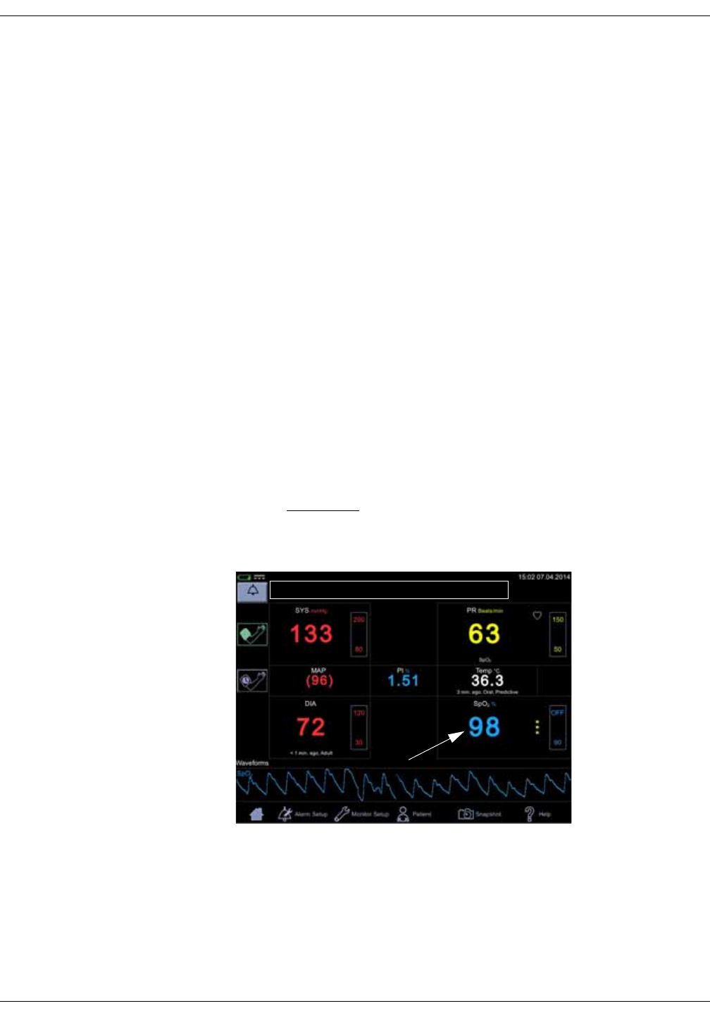
9-2 VC150 Vital Signs Monitor KO00065K
Nellcor SpO2: Description
Description
The SpO2 parameter in the monitor is available in three different technologies:
• GE TruSignal
• Nellcor OxiMaxTM
• Masimo rainbow® SET®
The SpO2 technology logo on the left side of the monitor, above the physical
connector, will disclose which technology the monitor is equipped with. If you
want to use a different SpO2 technology than your monitor is currently equipped
with, contact service to discuss the procedure. Use of Nellcor RR and Nellcor
Saturation Pattern Detection requires licenses that can be purchased separately
and may need specific accessories.
The SpO2 function is calibrated to read functional arterial oxygen saturation.
When a suitable SpO2 sensor is connected to the monitor and to the patient, the
measurement values will be shown on the screen. Pulse rate derived from SpO2
appears in the PR (Pulse Rate) window and updates continuously. The primary
source of pulse rate is always SpO2, i.e., if SpO2 is measuring when an NIBP
determination is completed, the pulse rate derived from NIBP is not displayed. A
tone sounds at a rate corresponding to the pulse rate and at a pitch
corresponding to the SpO2 saturation level. The pitch is highest at 100% oxygen
saturation, and it continuously decreases as the saturation level falls.
CAUTION
The pulse rate derived from SpO2 is a value calculated from oxygen
levels. The pulse rate is not equal to the patient’s actual heart rate.
Audible and visual alarms occur when SpO2 levels are outside the alarm limits.
and the monitor is in monitoring mode. When a parameter status alarm occurs,
an alarm message appears at the top of the screen (rectangle in the image
above).

KO00065K VC150 Vital Signs Monitor 9-3
Nellcor SpO2: Description
SpO2 safety
WARNINGS
Many factors may cause inaccurate readings and alarms, decreased
perfusion, and/or low signal strength:
Interfering substances:
- Carboxyhemoglobin may erroneously increase SpO2 readings.
- Methemoglobin (MetHb) usually represents less than 1% of the total
Hgb, but in the case of methemoglobinemia that can be congenital or
induced by some IV dyes, antibiotics (such as sulphas), inhaled gases,
etc., this level increases sharply. Methemoglobin may cause inaccurate
SpO2 readings.
- Intravascular dyes (such as indocyanine green, methylene blue, etc.) at
certain concentrations may cause inaccurate SpO2 readings and/or
decreased perfusion and corresponding signal strength, potentially
causing inaccurate SpO2 readings.
-Nail polish and artificial nails may cause inaccurate readings.
Physiological characteristics:
Some physiological characteristics may cause decreased perfusion
and/or low signal strength and may potentially cause inaccurate SpO2
readings:
- Cardiac arrest, hypotension, shock, severe vasoconstriction, severe
anemia, hypothermia, venous pulsations, congestions, darkly
pigmented skin, ventricular septal defects (VSDs)
Environmental conditions:
Some environmental conditions may cause interference or artifact and
may potentially cause inaccurate SpO2 readings.
- Excessive ambient light sources (e.g., infrared heat lamps, strobe
lights, bilirubin lights, direct sunlight, operating room lights). To prevent
such interference, cover the sensor with opaque material.
- Electrical interference/Electrosurgery
- Defibrillation - May cause inaccurate reading for a short amount of
time.
- Excessive patient/sensor motion. Artifact can simulate an SpO2
reading, so that the monitor fails to sound an alarm. In order to ensure
reliable patient monitoring, the proper application of the probe and the
signal quality must be checked at regular intervals.
Sensor placement:
- Sensor placement on the same extremity as a blood pressure cuff,
arterial catheter or intravascular line; or arterial occlusion proximal to
the sensor; or a sensor below the heart level may cause decreased
perfusion and/or low signal strength and potentially cause inaccurate
SpO2 readings.
- Poor sensor fit may cause decreased or low signal strength and
potentially cause inaccurate SpO2 readings.
- Do not allow tape to block the sensor light emitter and detector as this
may cause decreased perfusion and/or low signal strength and
potentially cause inaccurate SpO2 readings.
- Before using the Nellcor sensor, carefully read the Nellcor sensor
instructions for use (document produced by Covidien).

9-4 VC150 Vital Signs Monitor KO00065K
Nellcor SpO2: Description
WARNING
As with any wrap or clip-on sensor, pressure is exerted. Be cautious in
using a wrap or clip-on sensor on patients with compromised
circulation (e.g., peripheral vascular disease or vasoconstricting
medications).
Allow sensor and cable to dry completely after cleaning. Moisture and
dirt on the connector can affect the measurement accuracy.
Inaccurate SpO2 data can result if a sensor is past its useful life.
Therefore, re-evaluate the measurement periodically by performing
additional assessment of the patient equipment, including
consideration of use of alternate monitoring methods such as direct
measurement of arterial oxyhemoglobin saturation (SaO2).
If the accuracy of any measurement does not seem reasonable, first
check the patient’s vital signs, then check for conditions that may cause
inaccurate SpO2 readings. If the problem is still not resolved, check the
SpO2 module or sensor for proper functioning.
Oximetry performance may be impaired when patient perfusion is low
or signal attenuation is high.
If the perfusion index falls below 0.5%, the SpO2 values may be
inaccurate.
A pulse oximeter or CO-oximeter should not be used as an apnea
monitor.
A pulse oximeter should be considered an early warning device. As a
trend toward patient deoxygenation is indicated, blood samples should
be analyzed by a laboratory CO-oximeter to completely understand the
patient's condition. Check that the pulse oximetry waveform is
physiological in shape to ensure waveform quality and minimize noise
spikes caused by motion conditions.
If you deactivate the SpO2 Sensor Off alarm, keep the patient under
close surveillance.
Single-use products are not designed to be reused. Reuse may cause a
risk of cross-contamination, affect the measurement accuracy and/or
system performance, and cause a malfunction as a result of the
product being physically damaged due to cleaning, disinfection, re-
sterilization and/or reuse.
Clean the surface of the probe before and after each patient use.
Do not loop the sensor cable into a tight coil or wrap around the device,
as this can damage the sensor cable.

KO00065K VC150 Vital Signs Monitor 9-5
Nellcor SpO2: Description
CAUTIONS
Do not sterilize reusable sensors by irradiation, steam, or ethylene
oxide. See the sensor manufacturer's instructions for cleaning,
sterilization, or disinfecting methods.
Do not place SpO2 sensor on patient during magnetic resonance
imaging (MRI). Adverse reactions include potential burns to patients as a
result of contact with attachments heated by the MRI radio frequency
pulse, potential degradation of the magnetic resonance image, and
potential reduced accuracy of SpO2 measurements. Always remove
oximetry devices and attachments from the MRI environment before
scanning a patient.
Pulse oximetry readings and pulse signals can be affected by certain
environmental conditions, sensor application errors, and certain patient
conditions. See the appropriate sections of this manual for specific
safety information.
Placing a sensor distal to an arterial line may interfere with adequate
arterial pulsation and compromise the measurement of SpO2.
The sensor disconnect error message and associated alarm indicate
that the sensor is either disconnected or the wiring is faulty. The user
should check the sensor connection and, if necessary, replace the
sensor, interconnect cable, or both.
Placing a sensor on a polished or an artificial nail may affect accuracy.
Patient safety:
Do not place any clip-on sensor in a patient’s mouth, on their nose or
toes, on their thumb, or across a child’s foot or hand.
Prolonged monitoring or incorrect sensor application can cause skin
irritation or impaired circulation. Observe the sensor site frequently to
assure adequate distal circulation. Sensor sites should be checked at
least every 2 hours and rotated at least every 4 hours. Refer to
instructions supplied with sensor.
If the sensor is not applied properly, the patient’s skin could be injured or
the ability of the monitor to measure oxygen saturation could be
compromised. For example, a clip-on sensor should never be taped
shut. Taping the sensor could damage the patient’s skin or impair the
venous return, thus causing venous pulsation and inaccurate
measurement of oxygen saturation.
Excessive pressure from the sensor may cause necrosis of the skin.
The operating range for respiration rate is 4 to 40 breaths per minute.
Use on patients with respiration rates outside this range may result in
inaccurate displayed respiration rate values.

9-6 VC150 Vital Signs Monitor KO00065K
Nellcor SpO2: Description
CAUTIONS
Monitor performance:
Place the sensor so that the LEDs and the photodiode are opposite each
other.
Monitor performance:
When an SpO2 sensor is located on the same limb as the NIBP cuff, SpO2
readings will not be valid while the cuff is inflated. If valid SpO2 readings
are required during the entire blood pressure determination, attach the
SpO2 sensor to the limb opposite the one with the blood pressure cuff.
NOTES
• A patient’s vital signs may vary dramatically during the use of
cardiovascular agents such as those that raise or lower blood pressure or
those that increase or decrease pulse rate.
•SpO
2 and pulse rate values are filtered by an averaging technique, which
determines how quickly the reported values respond to changes in the
patient’s saturation. Increased averaging time effects time to alarm for SpO2
saturation and pulse rate limits.
• Pulse rate measurement is based on the optical detection of a peripheral
flow pulse and therefore may not detect certain arrhythmias. The pulse
oximeter should not be used as a replacement or substitute for ECG based
arrhythmia analysis.
• Software development, software validation, and risk and hazard analysis
have been performed to a registered quality system.
• A functional tester cannot be used to assess the accuracy of a pulse
oximeter probe or a pulse oximeter monitor.
• The pulse oximeter cannot distinguish between oxyhemoglobin and
dyshemoglobins.
• Poor perfusion may affect the accuracy of measurement, especially when
using an ear sensor.
• Check that the red light is lit in the sensor.
• Check that the waveforms (if enabled in monitor setup) and parameter
values are displayed when the sensor is connected to the patient.

KO00065K VC150 Vital Signs Monitor 9-7
Nellcor SpO2: Description
Inaccurate Sensor Measurement Conditions
A variety of conditions can cause inaccurate sensor measurements.
• Incorrect application of the recommended sensor
• Placement of the recommended sensor on an extremity with a blood
pressure cuff, arterial catheter, or intravascular line
•Ambient light
• Failure to cover the sensor site with opaque material in high ambient light
conditions
• Excessive patient activity
• Dark skin pigment
• Intravascular dyes or externally applied coloring, such as nail polish or
pigmented cream
• Excessive patient talking
• Respiration rate outside the range of 4 to 40 breaths per minute
• Significantly irregular cardiac rhythms (three or more events of irregularity
observed within 30 seconds)
Signal Loss
Loss-of-pulse signal can occur for several reasons.
• Recommended sensor applied too tightly
• Inflation of a blood pressure cuff on the same extremity as the attached
sensor
• Arterial occlusion proximal to the recommended sensor
• Poor peripheral perfusion
Recommended Usage
Select an appropriate recommended sensor, apply it as directed, and observe all
warnings and cautions presented in the Instructions for Use accompanying the
sensor. Clean and remove any substances such as nail polish from the
application site. Periodically check to ensure that the recommended sensor
remains properly positioned on the patient.
High ambient light sources such as surgical lights (especially those with a xenon
light source), bilirubin lamps, fluorescent lights, infrared heating lamps, and
direct sunlight can interfere with sensor performance. To prevent interference
from ambient light, ensure the recommended sensor is properly applied and
cover the sensor with opaque material.

9-8 VC150 Vital Signs Monitor KO00065K
Nellcor SpO2: Description
If patient activity presents a problem, try one or more of the following remedies
to correct the problem.
• Verify the sensor is properly and securely applied.
• Move the sensor to a less active site.
• Use an adhesive sensor that improves patient skin contact.
• Use a new sensor with fresh adhesive backing.
• Keep the patient quiet and still, if possible.
Patient Conditions
Application issues and certain patient conditions can affect the measurements
of the monitoring system and cause the loss of the pulse signal.
•Anemia — Anemia causes decreased arterial oxygen content.
Although SpO2 readings may appear normal, an anemic patient
may be hypoxic. Correcting anemia can improve arterial oxygen
content. The pulse oximeter may fail to provide an SpO2 reading if
hemoglobin levels fall below 5 gm/dl.
•Dysfunctional hemoglobins — Dysfunctional hemoglobins such as
carboxyhemoglobin, methemoglobin, and sulphemoglobin are
unable to carry oxygen. SpO2 readings may appear normal;
however, a patient may be hypoxic because less hemoglobin is
available to carry oxygen. Further assessment beyond pulse
oximetry is recommended.
•Additional possible patient conditions may also influence
measurements.
– Poor peripheral perfusion
– Excessive patient activity
– Venous pulsations
– Dark skin pigment
– Intravascular dyes, such as indocyanine green or methylene blue
– Externally applied coloring agents (nail polish, dye, pigmented
cream)
– Defibrillation
– Excessive patient talking
– Respiration rate outside the range of 4 to 40 breaths per minute
– Significantly irregular cardiac rhythms (three or more events of
irregularity observed within 30 seconds)
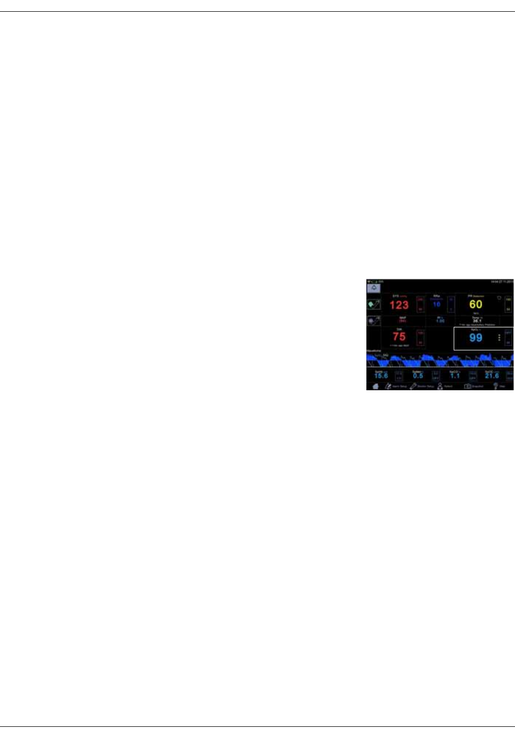
KO00065K VC150 Vital Signs Monitor 9-9
Nellcor SpO2: Related documents
Related documents
•Pulse Oximetry Sensor Instructions for Use — Guides sensor selection and
usage. Before attaching any of the various Covidien-approved Nellcor™
sensors to the monitoring system, refer to their Instructions for Use.
•Saturation Accuracy Grid — Provides sensor-specific guidance related to
desired SpO2 saturation accuracy measurements. Available online at
www.covidien.com.
SpO2 on the screen
When SpO2 is not receiving measurement data, a double dash (--) appears in this
window. When the sensor switches to operation mode, the SpO2 parameter
starts to receive data. If the data is valid, the derived SpO2 value appears in this
window and updates continuously. The values are displayed in %.
SpO2 values are displayed on the lower right
side of the monitor screen. The SpO2 and PI
values are displayed in cyan color by
default. This can be changed in
configuration mode. If the monitor is
providing the temperature measurement
the SpO2 value will be located under the
displayed temperature value.
The SpO2 field consists of the SpO2 label, the
measured value in the middle and the measurement site underneath the
parameter value. The measurement site choices are: Finger, Nose, Toe, Earlobe.
The site name Other can be used to indicate it was none of the above. The
default site is None. Next to the measured value is a column of asterisks
representing signal quality, as well as upper and lower limits for the SpO2 value.
If the sensor is detached from the patient, the SpO2 status switches to ‘off
patient’ and displays --.
NOTES
If pulse rate data from SpO2 data is available, the Pulse Rate window is
associated with this parameter and a heart symbol is displayed on screen.
Refer to “Pulse rate” on page 10-1 for more information.
If accuracy for a SpO2 derived parameter is not yet guaranteed, a dimmed
value is displayed on screen.
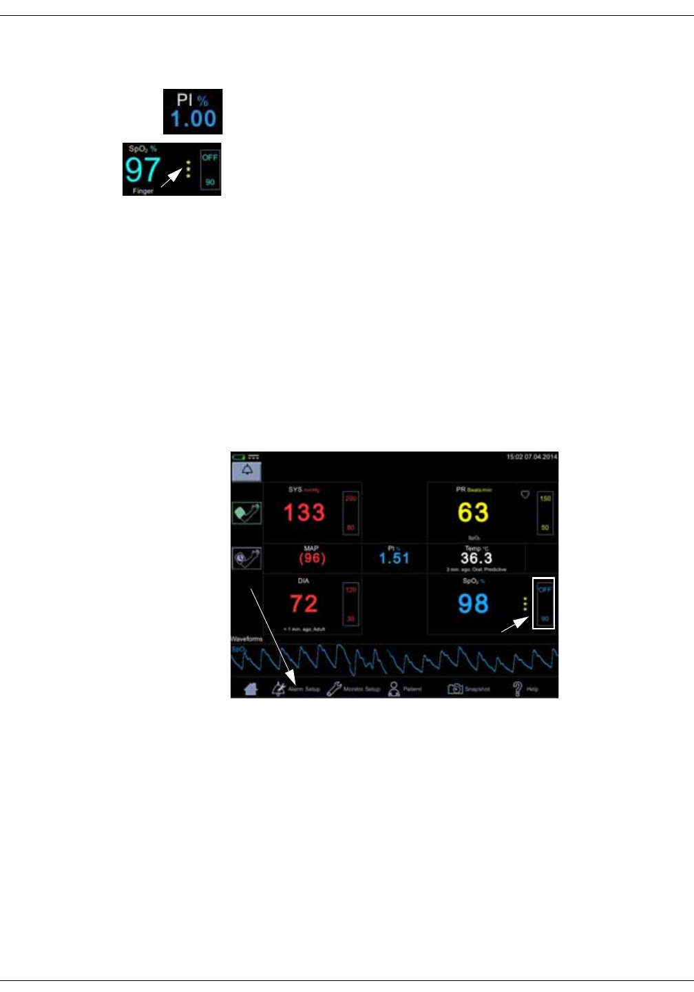
9-10 VC150 Vital Signs Monitor KO00065K
Nellcor SpO2: SpO2 on the screen
Perfusion index measurement
The perfusion index (PI) measurement is a clinical tool that provides a dynamic
numeric reflection of perfusion at the sensor site. PI is a relative value that varies
from patient to patient. The perfusion index value appears in its own field under
the label PI. The user can use the PI value to compare the strength of the pulse
signal at different sites on a patient in order to locate the best site for the sensor,
i.e., the site with the strongest pulse signal.
Signal Strength values are mathematically calculated perfusion values
represented by asterisks. The SpO2 signal strength should be adequate. This is
indicated by the display of two or three asterisks or the absence of a Low Signal
Quality message. The more asterisks there are the better the signal quality. The
better the arterial blood flow is, the better signal quality is obtained. A strong
pulse signal increases the validity of SpO2 and pulse rate data.
Changing the SpO2 alarm limits
SpO2 alarm limit adjustments can be set either A) by entering upper and lower
limit values directly in a limit box on the home screen as instructed in “Using the
numeric keypad” on page 3-12 or B) by adjusting limit values in the Alarm Setup
screen as instructed in “Procedure for testing alarms” on page 3-11.
Pleth
The Plethysmographic waveform (Pleth) represents a real-time waveform for the
relative SpO2 pulsatile amplitude. The Pleth waveform is always automatically
scaled to fit the window for the best display quality. The waveform uses the
same color as the SpO2 field.
A
B
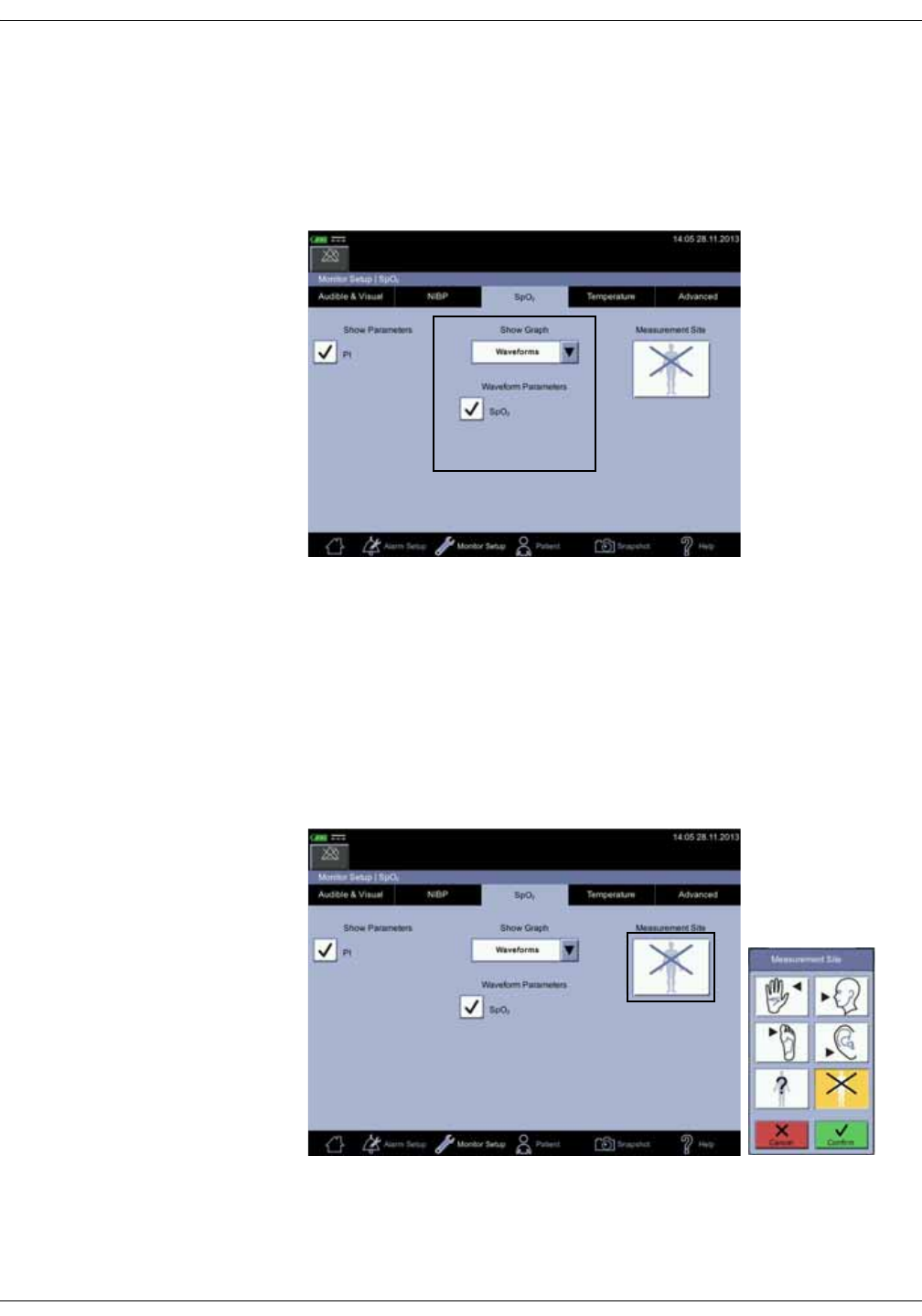
KO00065K VC150 Vital Signs Monitor 9-11
Nellcor SpO2: SpO2 on the screen
Pleth waveform settings
Select Waveforms in the drop-down menu under Show Graph in the Monitor
Setup > SpO2 to display the Pleth. Also select parameters to be displayed as
waveforms (availability depends on which SpO2 technology the monitor is
equipped with and which options have been purchased).
SpO2 measurement site
For documentation purposes, you can select the measurement site for SpO2 in
Monitor Setup > SpO2 before you start measuring SpO2. A pop-up screen with
the following images will appear: Finger, Nose, Toe, Earlobe, Other or None. It
does not matter whether the site is on the left or right side of the patient. After
the site is selected, it will be displayed on the home screen in the SpO2
parameter window. The selection can be changed between the measurements.
Admitting a new patient will reset the selection of the measurement site.

9-12 VC150 Vital Signs Monitor KO00065K
Nellcor SpO2: SpO2 procedure
SpO2 procedure
1. Check the label on the monitor to determine which SpO2 technology the
monitor is using. To assure optimal performance, use only accessories that
are intended for that technology. If you cannot read the label, ask the nurse
manager or service which SpO2 technology is used.
2. Select a sensor that is appropriate for the patient, the clinical situation and
for the SpO2 technology used. Do not use an adult sensor on a neonatal/
pediatric patient and vice versa.
WARNING
Do not use a sensor, cables, or connectors that appear damaged or
with exposed electrical contacts.
Never repair a damaged sensor or cable; never use a sensor or cable
repaired by others.
3. Ensure the VC150 is connected to power or the battery is fully charged.
4. Ensure the VC150 is powered on. The monitor has to display clinical mode
and SpO2 parameter on screen.
5. Connect an interface cable to the monitoring system sensor port.
6. Connect a correct sensor is connected to the interface cable and correctly
applied to the patient as described in the Instructions for Use. The VC150
reports the appropriate sensor type in the message field when it detects the
sensor. To obtain respiration rate, caregivers must use a Nellcor™
Respiratory Sensor and place it on the finger as described in sensor
instructions. If Respiration Sensor is used: contact Innokas Medical service to
upgrade the VC150 if the respiration rate parameter does not appear on the
screen.
7. Select the measurement site in Monitor Setup > SpO2, if desired. A shortcut:
Select SpO2 parameter area on the home screen to jump to the SpO2 screen.
8. Following the directions for use supplied with the sensor, apply the sensor to
the patient.
9. Proceed with monitoring. SpO2 measurements run continuously and can run
simultaneously with other measurements.
10. Clean the sensor as instructed in “Cleaning SpO2 sensors” on page B-8”.
SpO2 sounds
The monitor provides an audible tone for each pulse detected by the SpO2
parameter. The pitch of the audible tone is directly related to the calculated
saturation value. As the saturation value increases, the pitch rises. As the
saturation value decreases, the pitch frequency goes down. This audible tone is
silenced while an alarm sounds or the Day Volume or Night Volume is set to 0.
Refer to “Audible & Visual” on page 3-19 in this section.

KO00065K VC150 Vital Signs Monitor 9-13
Nellcor SpO2: Alarms
Alarms
If the SpO2 parameter determines the signal to be valid, SpO2 values are
displayed. In case the signal quality deteriorates to a questionable level, the
SpO2 or Pulse Rate values disappear from the screen and an alarm message for
lost pulse signal is generated.
NOTE
The advanced signal processing of the Nellcor OxiMax™ algorithm
automatically extends the amount of data required for measuring SpO2 and
pulse rate depending on the measurement conditions. The OxiMax™
algorithm automatically extends the dynamic averaging time required
beyond seven (7) seconds during degraded or difficult measurement
conditions caused by low perfusion, signal artifact, ambient light,
electrocautery, other interference, or a combination of these factors, which
results in an increase in the dynamic averaging. The OxiMax™ algorithm
continues to display SpO2 and Pulse Rate values under such conditions. If
the data update period exceeds 20 seconds, a Pulse search message is
displayed in SpO2 parameter window. If the data update period exceeds 30
seconds and the monitor alarms are enabled in monitoring mode, a low
priority alarm is generated. If the data update period exceeds 40 seconds
for SpO2 or 50 seconds for Pulse Rate, the values disappear from the display,
indicating a loss-of-pulse condition.
Alarm timer
The user can select between monitoring mode and spot-check mode. In spot-
check mode, clinical alarms and related functions are not available. If an SpO2
measurement continues for 5 minutes uninterrupted, the monitor automatically
moves from spot-check mode to monitoring mode. The alarms will be enabled in
monitoring mode.
If the probe is taken off and you want to measure the same patient without
alarms, select spot-check mode again.
NOTE
To prevent misuse of the device, duration of the SpO2 spot-check mode is
limited to 5 minutes.
If SpO2 is unable to be measured for some reason, then a technical status
message that indicates the reason for not measuring will appear below the
parameter value. If an abnormal technical status remains for ten seconds, then
a low priority alarm is created.
An abnormal technical status will create an alarm in both spot-check and
monitoring mode.

9-14 VC150 Vital Signs Monitor KO00065K
Nellcor SpO2: Compatible Nellcor accessories
Compatible Nellcor accessories
All approved and VC150 compliant accessories are listed in the VC150 supplies
and accessories document. Use only accessories listed in that document. If you
already have an accessory that you want to use with the VC150 monitor, check
whether it is listed in that document. If it not listed, do not use it with the VC150
monitor.
Nellcor SpO2 and special features
Theoretical principles
The Nellcor SpO2 uses pulse oximetry to measure functional oxygen saturation
in the blood. Pulse oximetry works by applying a Nellcor™ sensor to a pulsating
arteriolar vascular bed, such as a finger or toe. The sensor contains a dual light
source and a photodetector. Bone, tissue, pigmentation, and venous vessels
normally absorb a constant amount of light over time. The arteriolar bed
normally pulsates and absorbs variable amounts of light during the pulsations.
The ratio of light absorbed is translated into a measurement of functional
oxygen saturation (SpO2).
Ambient conditions, sensor application, and patient conditions can influence the
ability of the monitoring system to accurately measure SpO2. Pulse oximetry is
based on two principles: oxyhemoglobin and deoxyhemoglobin differ in their
absorption of red and infrared light (measured using spectrophotometry), and
the volume of arterial blood in tissue (and hence, light absorption by that blood)
changes during the pulse (registered using plethysmography).
A monitoring system determines SpO2 by passing red and infrared light into an
arteriolar bed and measuring changes in light absorption during the pulsatile
cycle. Red and infrared low-voltage light-emitting diodes (LED) in the sensor
serve as light sources; a photo diode serves as the photo detector.
Since oxyhemoglobin and deoxyhemoglobin differ in light absorption, the
amount of red and infrared light absorbed by blood is related to hemoglobin
oxygen saturation.
The monitoring system uses the pulsatile nature of arterial flow to identify the
oxygen saturation of arterial hemoglobin. During systole, a new pulse of arterial
blood enters the vascular bed, and blood volume and light absorption increase.
During diastole, blood volume and light absorption reach their lowest point. The
monitoring system bases its SpO2 measurements on the difference between
maximum and minimum absorption (measurements at systole and diastole). By
doing so, it focuses on light absorption by pulsatile arterial blood, eliminating the
effects of nonpulsatile absorbers such as tissue, bone, and venous blood.
This signal is processed by the pulse oximeter to determine patient SpO2 and
pulse rate data, which are displayed on the monitor user interface, system
status, and alarm information. These data are stored on the monitor and
available for subsequent export.
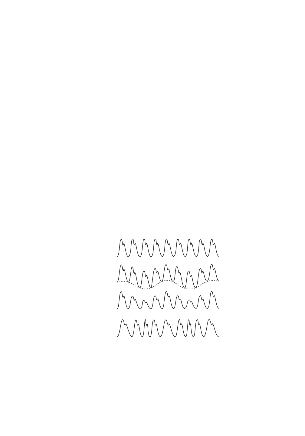
KO00065K VC150 Vital Signs Monitor 9-15
Nellcor SpO2: Nellcor SpO2 and special features
Nellcor Respiration Rate theory of operations
The Respiration Rate parameter, when used in conjunction with the VC150 and a
Nellcor™ Respiratory Sensor, provides continuous non-invasive monitoring of
arterial oxygen saturation, pulse rate and respiration rate using a single sensor.
The Respiration Rate parameter provides an indication of central ventilatory
drive by processing and interpreting the photoplethysmogram, or pleth.
The pleth signal is used to measure arterial oxygen saturation (SpO2). A typical
pleth pattern includes a regular cardiac 'pulse' waveform on top of a large
constant baseline component, or DC component. Refer to A in figure below.
In clinical settings, both the cardiac pulse and baseline components may vary
over time due to physiologic conditions and changes. In standard pulse
oximetry, these variations are typically filtered out in order to accurately
measure arterial oxygen saturation (SpO2). These same subtle variations,
however, may be used to derive respiration rate by tracking three types of
changes associated with the respiratory cycle.
1. Baseline (DC) variation — Changes in intrathoracic pressure during the
respiratory cycle influence venous return to the heart and result in baseline
DC variation in the pleth. Refer to B in figure below.
2. Pulse amplitude variation — Changes in intrathoracic pressure during
inspiration also lead to variation in cardiac stroke volume and result in pulse
amplitude variations. Refer to C in figure below.
3. Respiratory sinus arrhythmia (RSA) — During the respiratory cycle, heart rate
generally increases during inspiration and decreases during expiration. RSA
results in pulse frequency variations. Refer to D in figure below.
Variations of the pleth due to respiration
The Respiration Rate parameter utilizes these subtle pleth variations to measure
respiration rate. Note that the Respiration Rate parameter is an indicator of
central ventilatory drive and is not a direct measure of ventilation.
A
B
C
D

9-16 VC150 Vital Signs Monitor KO00065K
Nellcor SpO2: Nellcor SpO2 and special features
Nellcor™ Sensor Technology
Use Nellcor™ sensors, which are specifically designed for use with the
monitoring system. Identify Nellcor™ sensors by the Nellcor™ logo on the plug.
All Nellcor™ sensors contain a memory chip carrying information about the
sensor which the monitoring system needs for correct operation, including the
sensor’s calibration data, model type, troubleshooting codes, and error
detection data.
This unique oximetry architecture enables several new features. When a
Nellcor™ sensor is connected to the monitoring system, the monitoring system
reads the information from the sensor memory chip, ensures it is error free, and
then loads the sensor data prior to monitoring for new information. As the
monitoring system reads sensor information, it sends the sensor model number
to the monitoring screen. This process may take a few seconds. The sensor
model number disappears after the monitoring system starts tracking the
patient’s SpO2 and pulse rate.
Any monitoring system containing OxiMax technology uses calibration data
contained in the sensor in calculating the patient’s SpO2. With sensor calibration,
the accuracy of many sensors is improved, since the calibration coefficients can
be tailored to each sensor.
Contact Covidien or a local Covidien representative for a Sensor Accuracy Grid
listing all of the sensors used with the monitoring system. Covidien retains a soft
copy at www.covidien.com.
The monitoring system uses the information in the sensor, tailoring messages to
better help the clinician troubleshoot client or data issues. The sensor
automatically identifies its sensor type to the monitoring system when attached.
SatSeconds™ Alarm Management Parameter
The monitoring system monitors the percentage of hemoglobin binding sites
saturated with oxygen in the blood. With traditional alarm management, upper
and lower alarm limits are set to alarm at specific SpO2 levels. When the SpO2
level fluctuates near an alarm limit, the alarm sounds each time it violates the
alarm threshold. SatSeconds monitors both degree and duration of desaturation
as an index of desaturation severity. Thus, the SatSeconds parameter helps
distinguish clinically significant events from minor and brief desaturations that
may result in nuisance alarms.
Consider a series of events leading to a violation of the SatSeconds alarm limit.
An adult patient experiences several minor desaturations, then a clinically
significant desaturation.
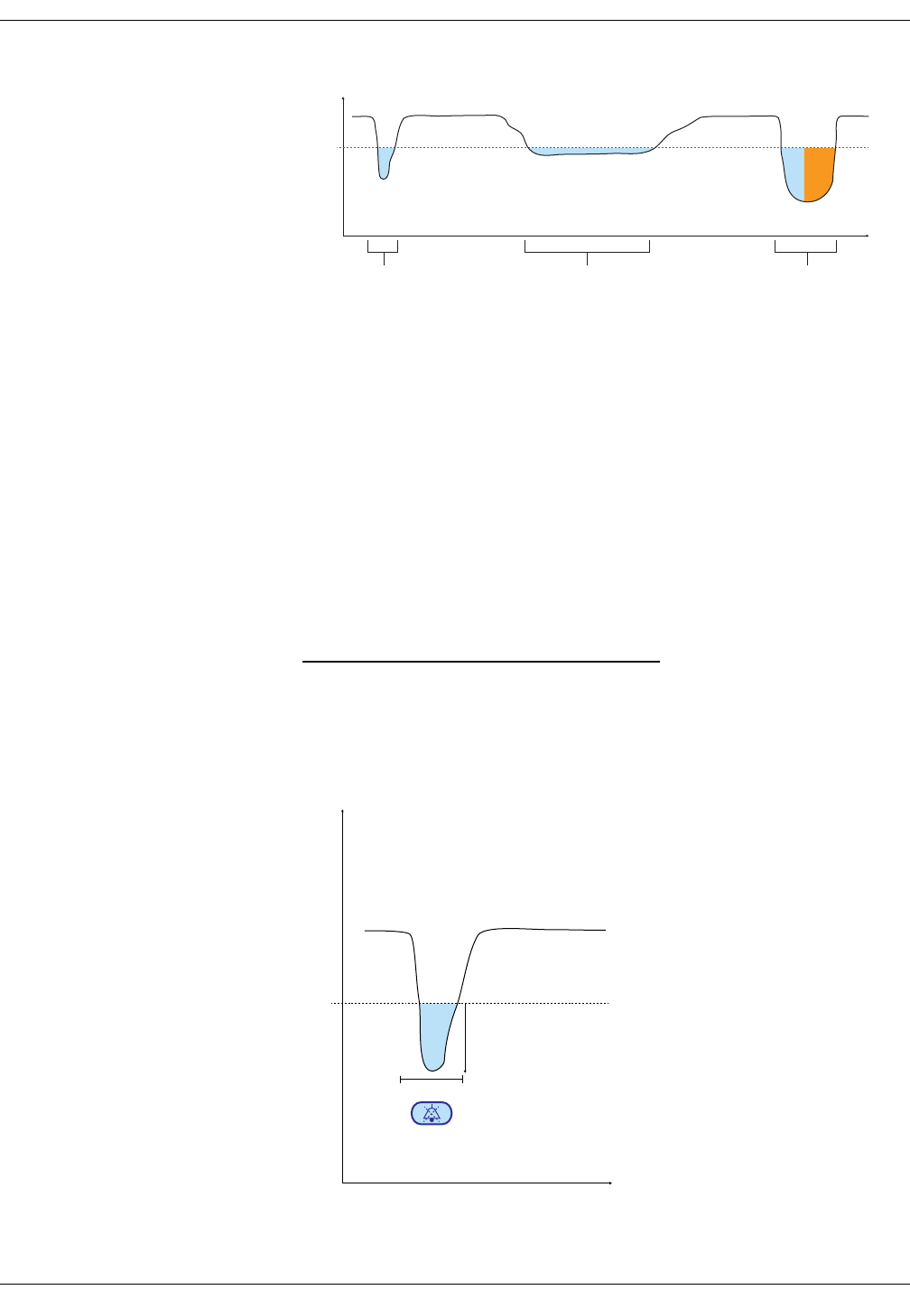
KO00065K VC150 Vital Signs Monitor 9-17
Nellcor SpO2: Nellcor SpO2 and special features
Series of SpO2 Events
a. First SpO2 Event
b. Second SpO2 Event
c. Third SpO2 Event
First SpO2 Event
Consider the first event. Suppose the SatSeconds alarm limit is set to 25. The
patient’s SpO2 drops to 79% and the duration of the event is two (2) seconds
before saturation again exceeds the lower alarm threshold of 85%.
Because the SatSeconds alarm limit is set to 25 and the actual number of Sat-
Seconds equals 12, there is no audible alarm.
First SpO2 Event: No SatSeconds Alarm
85
SpO2
s
ab c
6% drop below the lower alarm limit threshold
x 2 second duration below the lower threshold
12 SatSeconds; no alarm
2 s
12 SatSeconds
6%
0 2 4 6 8 10 S
100
98
96
94
92
90
88
86
84
82
80
78
76
74
SpO
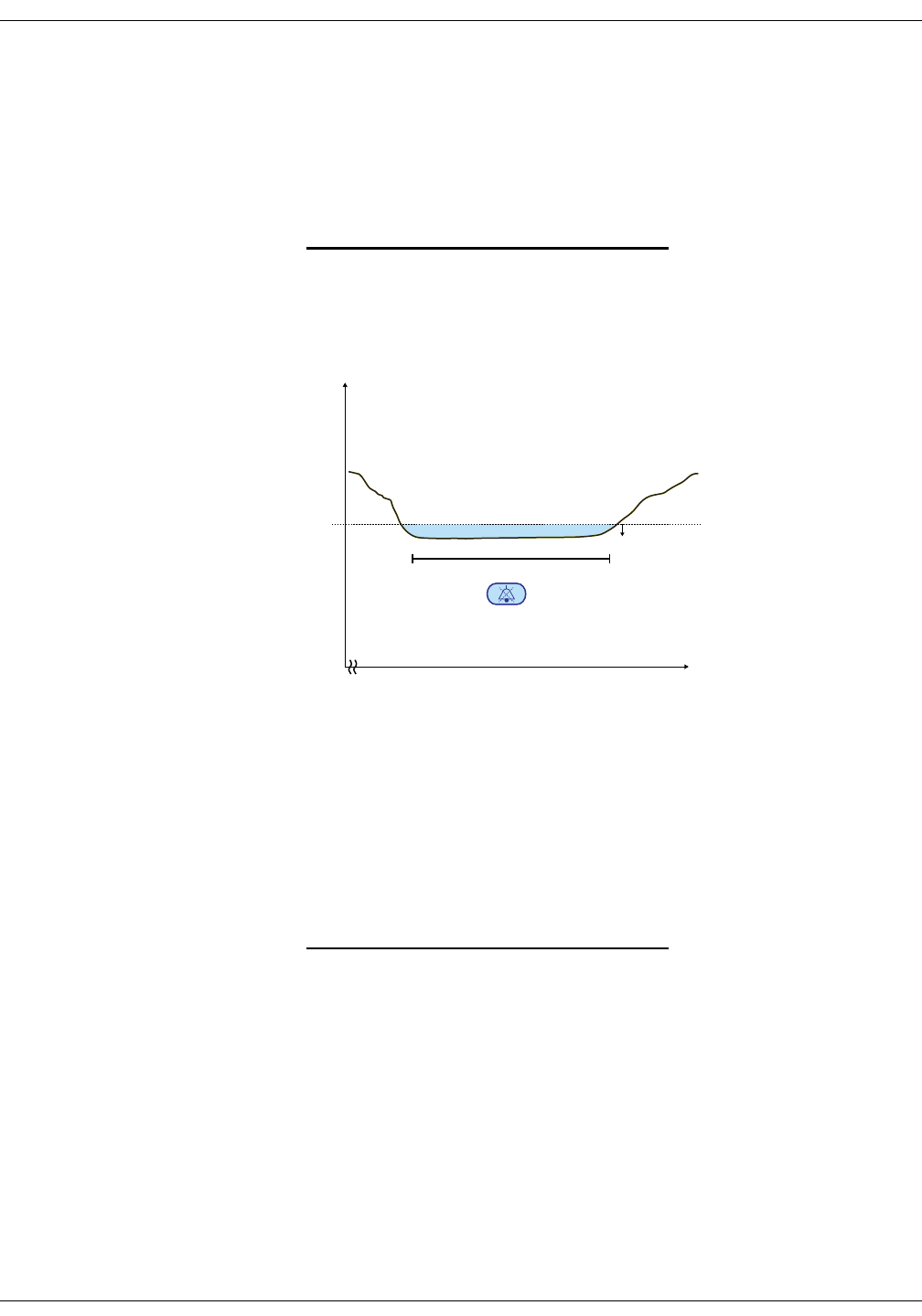
9-18 VC150 Vital Signs Monitor KO00065K
Nellcor SpO2: Nellcor SpO2 and special features
Second SpO2 Event
Consider the second event. Suppose the SatSeconds alarm limit is still set to 25.
The patient’s SpO2 drops to 84% and the duration of the event is 15 seconds
before saturation again exceeds the lower alarm threshold of 85%.
Because the SatSeconds alarm limit is set to 25 and the actual number of Sat-
Seconds equals 15, there is no audible alarm.
Second SpO2 Event: No SatSeconds Alarm
Third SpO2 Event
Consider the third event. Suppose the SatSeconds alarm limit is still set to 25.
During this event, the patient’s SpO2 drops to 75%, which is 10% below the lower
alarm threshold of 85%. Since the patient’s saturation does not return to a value
over the lower alarm threshold within 2.5 seconds, an alarm sounds.
At this level of saturation, the event cannot exceed 2.5 seconds without invoking
a SatSeconds alarm.
1% drop below the lower alarm limit threshold
x 15 second duration below the lower threshold
15 SatSeconds; no alarm
15 s
15 SatSeconds
0 16 18 20 22 24 S
100
98
96
94
92
90
88
86
84
82
80
78
76
74
SpO
1%
26 28 30 32 34
10% drop below the lower alarm limit threshold
x 2.5 second duration below the lower threshold
25 SatSeconds; results in an alarm
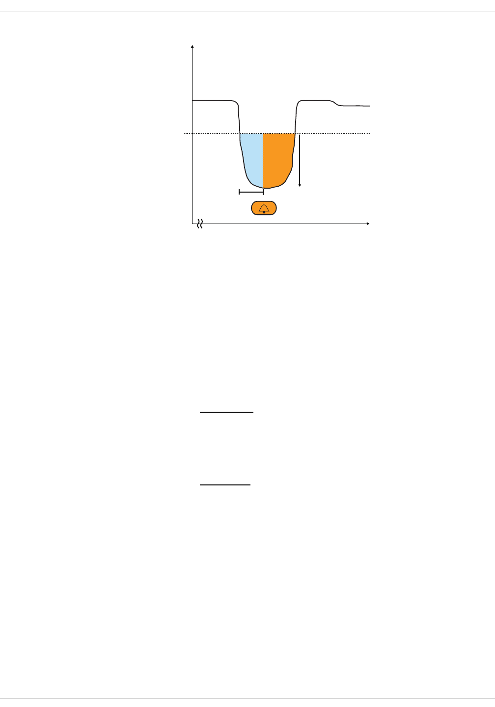
KO00065K VC150 Vital Signs Monitor 9-19
Nellcor SpO2: Nellcor SpO2 and special features
Third SpO2 Event: Triggers SatSeconds Alarm
The SatSeconds Safety Net
The SatSeconds “Safety Net” is for patients with saturation levels frequently
falling below the limit, but not staying below the limit long enough for the Sat-
Seconds time setting to be reached. When three or more limit violations occur
within 60 seconds, an alarm sounds even if the SatSeconds time setting has not
been reached.
OxiMax SPD™ Alert Parameter
WARNING
Supplemental oxygen will attenuate patterns of desaturation. A
patient’s respiratory compromise can be proportionally more severe
before patterns appear in the saturation trend. Remain vigilant when
monitoring a patient on supplemental oxygen.
CAUTION
Do not modify any other alarm settings while using the SPD™
parameter.
The OxiMax SPD™ Alert (SPD) method of detecting patterns of desaturation in
adults is a function of the software within the monitoring system, which detects
repetitive occurrences of desaturation followed by resaturation. These patterns
are indicative of repetitive reductions in airflow through the upper airway and
into the lungs. With the SPD parameter enabled, the default value for
SatSeconds alarms is 100.
2.5 s
25 SatSeconds
0 40 42 44 46 48 S
100
98
96
94
92
90
88
86
84
82
80
78
76
74
SpO
10%
50 52 54
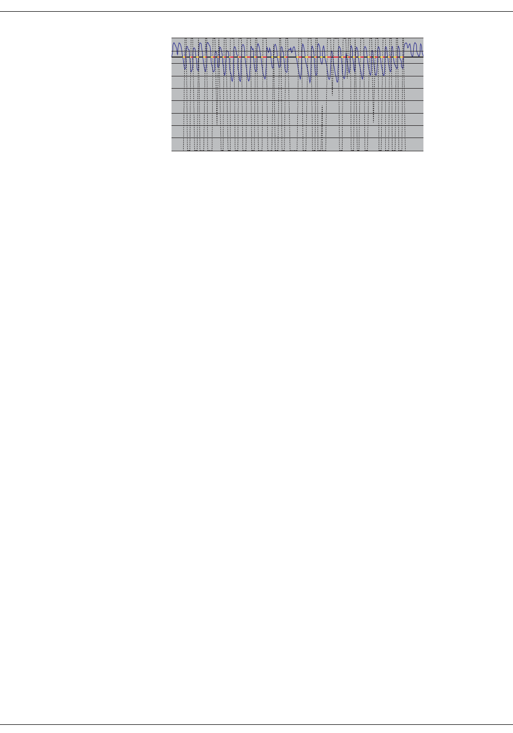
9-20 VC150 Vital Signs Monitor KO00065K
Nellcor SpO2: Nellcor SpO2 and special features
Clinically Significant Desaturation Patterns
The OxiMax SPD™ Alert (SPD) parameter detects patterns of desaturation in
adults that are indicative of repetitive reductions in airflow through a patient's
upper airway into the lungs. Relative reductions in a patient's minute ventilation
over a period of time may cause a progressive drop in alveolar partial pressure
of oxygen, leading to arterial desaturation. If these decreases in ventilation are
repetitive, they generate distinct patterns in the saturation trend. Patterns of
repetitive desaturation often develop gradually over time, increasing in severity.
Detection of patterns indicates that a patient might be suffering progressively
severe decrements in airflow that may increase in acuity if left untreated.
Patterns of desaturation are multiple, sequential occurrences of a desaturation
followed by a resaturation. The SPD™ parameter qualifies patterns of
desaturation resulting from such repetitive reductions in airflow based on
specific characteristics.
The SPD™ parameter qualifies these patterns of desaturation over a period of six
(6) minutes. Depending on the sensitivity setting for SPD, patterns that persist
may result in an SPD alarm, alerting the caregiver to the condition.
• The severity of the desaturation event (the depth of the desaturation during
the event) and the extent of the following resaturation
• The regularity of the desaturation events (how often the pattern repeats)
• The slope of the desaturation/resaturation trends that form the events
The SPD™ parameter communicates information to the caregiver about these
patterns of desaturation in a variety of ways with icons and alarms.
When the indicator reaches capacity, indicating the SPD™ limit has been
reached, an audible alarm sounds and an alarm message flashes. The default
setting of one (1) is the most sensitive to desaturation patterns and results in
more frequent alarms. For less frequent alarms, use a less sensitive setting of
two (2) or three (3).
NOTE
Unrecognized repetitive reductions in airflow through the upper airway
occur in some clinically significant scenarios. Patients exhibiting sleep
apnea symptoms were used in studies to validate the SPD™ Alert
parameter. The presence of repetitive reductions in airflow was scored using
a standard diagnostic polysomnogram. Study results indicate SPD is a
sensitive marker in detecting repetitive reductions in airflow.

KO00065K VC150 Vital Signs Monitor 9-21
Nellcor SpO2: Nellcor SpO2 and special features
Pulse Rate Delay Alarm Management Parameter
The monitoring system also monitors pulse rate by determining the number of
pleth waves over unit time. With traditional alarm management, upper and
lower alarm limits are set for monitoring pulse rate. When pulse rates fluctuate
near an alarm limit, alarms trigger with each violation. Pulse Rate Delay allows a
period of threshold violation before the pulse rate alarm sounds. Thus, it
distinguishes clinically significant events from minor and brief pulse rate limit
violations that result in nuisance alarms.
To use Pulse Rate Delay, set the traditional alarm management upper and lower
pulse rate alarm limits. Then, set Pulse Rate Delay. The Pulse Rate Delay limit
controls the time the pulse rate level crosses either limit before an audible alarm
sounds.
Required Pulse Oximetry Sensor Usage (for respiration rate)
To obtain respiration rate, caregivers must use a Nellcor™ Respiratory Sensor. If
caregivers use alternate sensors, listed in the Operator's Manual, the monitor
continues to post both SpO2 and pulse rate data and dashes in the RR field. If
caregivers use a respiratory sensor, the monitor will post both SpO2 and pulse
rate and respiration rate will be posted when enough data are available. The
monitor will display dashes in the RR field for instances where it is unable
calculate a respiration rate. If such is the case, examine all possible performance
considerations.
Prerequisites
Before starting a monitoring session, confirm the following:
• The monitoring system is powered on, has successfully completed its power-
on self-test, and has the respiration rate parameter enabled. Contact a qualified
service technician to have the monitoring system upgraded if the respiration
rate parameter does not appear on the screen.
• The monitoring system is connected to power or the battery is fully charged.
• An interface cable is connected to the monitoring system sensor port as
described in the Operator’s Manual.
• A respiratory sensor is connected to the interface cable and correctly applied
to the patient as described in the Instructions for Use. The monitoring system
reports the appropriate sensor type in the message field when it detects the
sensor.
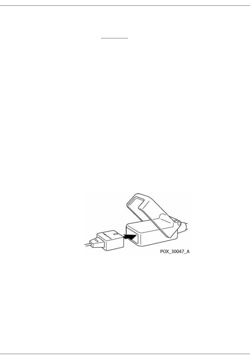
9-22 VC150 Vital Signs Monitor KO00065K
Nellcor SpO2: Nellcor SpO2 and special features
Connection to Nellcor™ Sensors
WARNING
Use only Covidien-approved sensors and interface cables when
connecting to the sensor port. Connecting any other cable or sensor
influences the accuracy of sensor data, which may lead to adverse
results.
The top of the monitoring system screen indicates the sensor type when
connecting a recommended sensor to the monitoring system or when the
monitoring system completes POST with an attached sensor.
NOTES
Physiological conditions such as excessive patient movement, medical
procedures, or external agents such as dysfunctional hemoglobin, arterial
dyes, low perfusion, dark pigment, and externally applied coloring agents
such as nail polish, dye, or pigmented cream may interfere with the
monitoring system¡¦s ability to detect and display measurements.
Sensor LED light emissions fall within Class 1 level, according to IEC 60825-
1:2001.
To fully connect a Nellcor sensor
1. Firmly connect a Nellcor interface cable to the monitoring system¡¦s sensor
port. Reference “Rear view and left side” on page 2-2, to identify the port.
2. Open the plastic latch at the other end of the interface cable.
3. Plug the interface cable and recommended sensor together.
4. Snap the plastic latch down over the connectors.
5. When the monitoring system detects a valid pulse, it enters the monitoring
mode and displays real-time patient data.
6. Apply the recommended sensor to the patient after reading the Instructions
for Use accompanying the sensor.
7. Detach the recommended sensor from the patient on completion of
monitoring.

KO00065K VC150 Vital Signs Monitor 9-23
Nellcor SpO2: Nellcor SpO2 and special features
WARNINGS
Nellcor-labeled monitors are only compatible with NellcorTM sensors
and accessories, which are available from your Innokas Medical
representative or from Nellcor or its local representative. Other sensors
or accessories may cause improper SpO2 performance. Use only
NellcorTM sensors with purple, white or navy blue plugs (connectors) and
cables. Use of another pulse oximetry cable will have an adverse effect
on performance. Do not attach any cable that is intended for computer
use to the sensor port.
For monitors with Nellcor technology, use only Covidien (Nellcor)TM
sensors and accessories. Incompatible components can result in
degraded performance and/or device malfunction.
Intravascular dyes (such as indocyanine green, methylene blue, etc.)
and darkly pigmented skin can adversely affect SpO2 readings.
Significant amounts of dysfunctional hemoglobins (such as
carboxyhemoglobin, methemoglobin, etc.) may adversely affect
oximetry performance.
Oximetry performance may be impaired when patient perfusion is low
or signal attenuation is high.
Long cables (such as the sensor or extension cable) may cause patient
strangulation if routed incorrectly.
Unless accessories and the monitor are used according to the
operator’s manual and in compliance with EMC standards,
electromagnetic interference by defibrillators, MRIs or electro-surgical
units may disturb the measurement process and cast doubt on its
reliability.
Nellcor™ Respiration Rate parameter is intended for the continuous
noninvasive monitoring of respiration rate in adult patients who are well
perfused during non-motion conditions. Oximax SPD™ Alert (SPD)
feature is intended only for facility-use care of adults to detect patterns
of desaturation indicative of repetitive reductions in airflow through the
upper airway and into the lungs.
RR is not a direct measure of ventilation; the clinician should always
consider clinical signs and symptoms when assessing the patient.
Do not use RR with patients with significantly irregular cardiac rhythms.
Certain types of disturbances may degrade RR accuracy or result in no
display.
The operating range for RR is 4 to 40 breaths per minutes. Use of RR on
patients who are breathing outside this range may result in inaccurate
RR values.
The RR software may give inaccurate readings due to aliasing
conditions, when patient's BRPM exceeds 50% of pulse rate.

9-24 VC150 Vital Signs Monitor KO00065K
Nellcor SpO2: Nellcor SpO2 and special features
WARNINGS
Supplemental oxygen will attenuate patterns of desaturation. A
patient’s respiratory compromise can be proportionally more severe
before patterns appear in the saturation trend. Remain vigilant when
monitoring a patient on supplemental oxygen.
Do not modify any other alarm settings while using the SPD™
parameter.
Use of the SPD™ parameter does not change the need to set threshold
limits appropriate to the patient being monitored.
Should the caregiver acknowledge an SPD™ alarm, this resets the index
that tracks repetitive patterns of desaturation.
External factors, including certain ambient conditions, sensor
application errors, and certain patient conditions, may compromise the
accuracy of the displayed respiration rate value. Always consider
clinical signs and symptoms when assessing the patient and before
intervening in response to a respiration rate alarm.
Respiration Rate is not intended for use as an apnea monitor. During
apnea, Respiration Rate may post a non-zero number.
Respiration Rate should not be used on patients with significantly
irregular cardiac rhythms (defined as three or more events of
irregularity observed within 30 seconds) because the presence of these
irregular cardiac rhythms may cause inaccurate respiration rate values
or the loss of displayed respiration rate information. Safety and
effectiveness of Respiration Rate in patients with significantly irregular
cardiac rhythms have not been established. Use an alternate means of
monitoring ventilatory status for patients with significant cardiac
dysrhythmia.
Safety and effectiveness of respiration rate in patients on mechanical
ventilation have not been established.
Safety and effectiveness of respiration rate in pediatric and neonatal
patients have not been established.
Safety and effectiveness of respiration rate in pregnant or lactating
women have not been established.
Use of the Respiration Rate parameter does not change the need to set
threshold limits appropriate to the patient being monitored.

KO00065K VC150 Vital Signs Monitor 9-25
Nellcor SpO2: Nellcor SpO2 and special features
CAUTIONS
The respiration rate value is generated from SpO2 to provide a reference
for respiration rate. It is not the actual value for the respiration rate.
SPD™ (Saturation Pattern Detection) can be used only if SatSeconds is
active. It cannot be used without SatSeconds.
Do not use NIBP or constricting instruments on the same appendage as
the sensor.
Do not simultaneously be in contact with device connectors and the
patient.
Do not immerse sensors.
Utilize hospital grade line cords in AC-powered systems.
Treat SPD™ alarm as lower priority than SatSeconds.
A low SpO2 alarm limit of at least 90% is recommended when
monitoring patients on supplemental oxygen.
Accuracy of Respiration Rate was established using bench-top testing
and clinical studies in 26 healthy volunteers and 53 hospitalized
patients. Hospital studies were conducted using convenience sampling
and did not necessarily include all patient conditions found in hospitals
and hospital-type settings. These clinical study results may not
generalize to all patient conditions. Use caution in patient populations
in which a displayed respiration rate value outside of the stated
accuracy specification could present a serious risk or hazard.
An SpO2 alarm may be the first indication of hypoventilation.
Respiration rate may present inaccurate respiration rate values when
respiration rate exceeds 50% of heart rate. This situation, though rare,
may occur under conditions including, but not limited to, any of the
following: patients with high respiration rate and low heart rate,
patients taking beta blockers, or patients with specific medical
conditions such as sick sinus syndrome.
Respiration rate provides an indicator of central ventilatory drive and
not a direct indication that air is moving through the upper airway.
Always consider clinical signs and symptoms when assessing the
patient and before intervening in response to a respiration rate alarm.
NOTE
Respiration Rate values are calculated every five seconds. Users should be
aware that the reported respiration rate represents an average over a
period of time and does not necessarily represent the instantaneous
respiration rate. Low and high respiration rate alarms are triggered
immediately when the reported rate falls outside the alarm limits and no
further alarm delay is applied.

9-26 VC150 Vital Signs Monitor KO00065K
Nellcor SpO2: Nellcor SpO2 default settings
Nellcor SpO2 default settings
Nellcor SpO2 - Default Setup > Alarm Defaults
SpO2Upper limit: OFF
Lower limit: 90%
Priority: Medium
Latching/Non-latching: Latching
RR Upper limit: 30 br/min
Lower limit: 6 br/min
Priority: Medium
Latching/Non-latching: Non-latching
PI Upper limit: OFF
Lower limit: OFF
Priority: OFF
Latching/Non-latching: Non-latching
Response Mode Normal
SPD Sensitivity OFF
SatSeconds OFF
Pulse Rate Alarm Delay OFF

KO00065K VC150 Vital Signs Monitor 9-27
Nellcor SpO2: Nellcor SpO2 default settings
Nellcor SpO2 configuration
Settings for specific Nellcor features can be selected in Alarm Setup (the monitor
must be in monitoring mode). Refer to the table below for more information.
Nellcor feature Description
Pulse Rate Alarm Delay
management parameter
The oximeter monitors pulse rate by determining the number of pleth waves over
unit time. With traditional alarm management, upper and lower alarm limits are set
for monitoring pulse rate. When the pulse rate fluctuates near an alarm limit, the
alarm sounds each time it violates an alarm limit. Use the Pulse Rate Delay feature to
distinguish clinically significant events from minor and brief pulse rate limit
violations that result in nuisance alarms. The Pulse Rate Delay feature allows a period
of threshold violation before the pulse rate alarm sounds. Thus, the Pulse Rate Delay
feature distinguishes clinically significant events from minor and brief pulse rate limit
violations that may result in nuisance alarms.
To use the Pulse Rate Delay feature, set the traditional alarm management upper and
lower pulse rate alarm limits. Then, set the Pulse Rate Delay. The Pulse Rate Delay
limit controls the time the pulse rate level crosses either limit before an audible alarm
sounds.
Options: Off, 5, 10 seconds
Response mode
The response mode establishes the frequency the oximeter uses to calculate, record,
and display SpO2 saturation levels, but does not affect the calculation of pulse rate.
The response mode, however, may impact the SPD™ (saturation pattern detection)
alarm. When in FAST response mode, the monitoring system may produce more SpO2
and pulse rate alarms.
Normal
The default response mode responds to changes in blood oxygen saturation in 5 to 7
seconds when calculating % SpO2. When in the normal mode, the screen does not
display the fast mode icon.
Fast
Fast mode responds to changes in blood oxygen saturation levels in 2 to 4 seconds
when calculating % SpO2. This can be particularly helpful for situations that require
close monitoring. The fast mode text in italics appears above the SpO2 parameter
value when in fast mode.

9-28 VC150 Vital Signs Monitor KO00065K
Nellcor SpO2: Nellcor SpO2 default settings
SatSeconds
alarm management
parameter
With traditional alarm management, upper and lower alarm limits are set for
monitoring SpO2. During monitoring, as soon as an alarm limit is violated by as little as
one percentage point, an audible alarm immediately sounds. When the percent SpO2
fluctuates near an alarm limit, the alarm sounds each time the limit is violated.
To prevent these nuisance alarms, the SatSeconds alarm management feature
controls the time that the percent SpO2 level may fall outside the alarm limits before
an audible alarm sounds. Choose either Off, 10, 25, 50, or 100 seconds. SatSeconds is
always 100 when SPD™ is active. The SatSeconds number is calculated by taking the
amount the current saturation value is out of limits and multiplying it by the amount of
time it has been out of those limits. For example, at a SatSeconds setting of 50, an
alarm goes off if the patient is:
• 5 points below the threshold × 10 seconds
• 10 points below the threshold × 5 seconds
The SatSeconds “safety net” is for patients with saturation levels frequently falling
below the limit, but not staying below the limit long enough for the SatSeconds time
setting to be reached. If the patient has had three or more SpO2 threshold violations
within a 60-second period, the alarm will sound whether or not the patient has
exceeded the SatSeconds setting.
For mild or brief SpO2 limit violations, use the Sat-Seconds parameter to reduce
nuisance alarms. With the SatSeconds parameter enabled, the monitoring screen
includes a circle icon and its setting. The SatSeconds alarm limit value appears just
below the circle icon. When the SatSeconds parameter is enabled, the circle icon fills
in the clockwise direction as the alarm management system detects SpO2 readings
outside of the limit setting. The circle icon empties in counterclockwise direction when
SpO2 readings are within limits. When the icon fills completely, a medium-priority
alarm sounds.
The SatSeconds feature is indicated by a dashed circle icon with the current limit
value below the icon. The icon fills clockwise in one-sixteenth increments by the ratio
of current SatSeconds value to the current SpO2 alarm limit.
Nellcor feature Description
KO00065K VC150 Vital Signs Monitor 9-29
Nellcor SpO2: Nellcor SpO2 default settings
NOTE
Unrecognized repetitive reductions in airflow through the upper airway
occur in some clinically significant scenarios. Patients exhibiting sleep
apnea symptoms were used in studies to validate the SPD™ Alert
parameter. The presence of repetitive reductions in airflow was scored using
a standard diagnostic polysomnogram. Study results indicate SPD is a
sensitive marker in detecting repetitive reductions in airflow.
Recommended actions for the use of Nellcor SpO2
• Consult sensor directions for use for proper sensor application.
• Inspect extension cables and sensors periodically for damage and
discontinue the use of these if damage is found.
• Implement a periodic testing strategy. Hand-held, battery-operated pulse
simulation testers (SRC-MAX) are available from Covidien (Nellcor). Contact
Nellcor’s Technical Services Department at 1.800.635.5267 (U.S. only), or
your local Nellcor representative.
• Review safety labeling based on the intended use of the equipment.
OxiMax SPD™ Alert
Parameter
Use the SPD™ alert (saturation pattern detection, SPD) parameter to detect patterns of
desaturation in adults that are indicative of repetitive reductions in airflow through a
patient's upper airway into the lungs. Patterns of desaturation are multiple, sequential
occurrences of a desaturation followed by a resaturation. The SPD parameter qualifies
patterns of desaturation resulting from such repetitive reductions in airflow based on
specific characteristics. The SPD parameter qualifies these patterns of desaturation
over a period of six (6) minutes. Depending on the sensitivity setting for SPD, patterns
that persist may result in an SPD alarm, alerting the caregiver to the condition.
• The severity of the desaturation event (the depth of the desaturation during the
event) and the extent of the following resaturation
• The regularity of the desaturation events (how often the pattern repeats)
• The slope of the desaturation/resaturation trends that form the events
The SPD™ alert uses a dashed triangle icon that is filled in one-third increments. When
the triangle is filled up, it triggers an alarm to alert staff about these suspicious
patterns.
Using the SPD™ Alert parameter also triggers the SatSeconds parameter. With the
SPD parameter enabled, the monitoring screen includes both triangle and circle icons
and their settings. The SPD alarm sensitivity value appears just below the triangle icon.
When the SPD parameter is enabled, the triangle icon fills from bottom to top as
desaturation patterns develop. The triangle icon empties from top to bottom as
patterns dissipate. When the icon fills completely, a low-priority alarm sounds. The
monitoring system will sound the SPD alarm sooner if the SPD alarm sensitivity is set
to the default value of one (1). A less sensitive setting will result in less frequent alarms.
Options: Off, 1 - Most sensitive, 2 - Moderately, 3 - Least
Nellcor feature Description

9-30 VC150 Vital Signs Monitor KO00065K
Nellcor SpO2: Nellcor SpO2 specifications
Nellcor SpO2 specifications
NOTE
For detailed information on patient population, sensor site and application
refer to Nellcor sensor instructions for use.
Measurement range
SpO21 to 100%
Pulse rate 20 to 250 bpm
Perfusion range 0.03 to 20%
RR measurement range and accuracy 4 to 40 breaths/minute, ±1 breath/minute
Data update
Data update period <2 seconds
Averaging Time
During normal measurement conditions in the Normal mode, the SpO2 averaging time is six (6) to seven (7) seconds or
approximately three (3) seconds in Fast mode.
Oxygen Saturation Accuracy1
Sensor Model Type LoSAT Range 60% to Standard Range 70% to
MAX-A, MAX-AL ± 3.0 digits ± 2.0 digits
MAX-N2 (Adult and Neonatal) ± 3.0 digits ± 2.0 digits
MAX-P, MAX-I, Forehead SpO2 Sensor ± 3.0 digits ± 2.0 digits
SpO2 Non-adhesive, Adult, Neonatal, Preemie3N/A ± 3.5 digits
MAX-R N/A ± 2.0 digits
Low perfusion 4N/A ± 2.0 digits
The root mean square of the difference (rmsd) for set SpO2 and displayed SpO2 was 0.727. Seventy data points were
taken in the test in the 70 to 100% saturation range. The root mean square of the difference (rmsd) for set PR and
displayed PR was 1.581. Seventy data points were taken in the test in the 40 to 250 BPM pulse rate. All data for this
test is stored at Nellcor/Covidien.

KO00065K VC150 Vital Signs Monitor 9-31
Nellcor SpO2: Nellcor SpO2 specifications
Pulse Rate Accuracy
Normal range 20 to 250 bpm ±3 bpm (rms)
Low perfusion** 20 to 250 bpm ±3 bpm (rms)
*Adult specifications are shown for OXIMAX MAX-A and MAX-N sensors with the N-600.
Saturation accuracy will vary by sensor type. This variation equals plus or minus one standard deviation. Plus or minus
one standard deviation encompasses 68% of the population. Accuracy is based on deep hypoxia studies on healthy
adult volunteer subjects. Arterial blood samples were analyzed simultaneously on multiple CO-oximeters.
**Applicability: OXIMAX MAX-A, MAX-AL, MAX-P, MAX-I, and MAX-N sensors.
1 Subjects used to validate SpO2 measurement accuracies were healthy and recruited from the local population.
Comprised of both men and women, subjects spanned a range of skin pigmentations and ranged in age from 18-50
years old. Accuracy specifications are based on controlled hypoxia studies with healthy non-smoking adult volunteers
over the specified saturation SpO2 range(s). Pulse oximeter SpO2 readings were compared to SaO2 values of drawn
blood samples measured by hemoximetry. All accuracies are expressed as ±1 SD. Pulse oximeter equipment
measurements are statistically distributed; about two-thirds of pulse oximeter measurements can be expected to fall
in this accuracy (Arms) range. Because scatter and bias of pulse oximeter SpO2 and blood SaO2 comparison
commonly increase as the saturation decreases, and accuracy specifications are calculated from data spanning the
stated range, different accuracy values may result when describing partially overlapping ranges.
2 Clinical functionality of the MAX-N has been demonstrated on a population of hospitalized neonate patients. The
observed SpO2 accuracy was 2.5% in a study of 42 patients with ages of 1 to 23 days, weight from 750 to 4,100
grams, and 63 observations made spanning a range of 85% to 99% SaO2.
3 Clinical functionality has been demonstrated in a population of hospitalized neonate patients. The observed SpO2
accuracy was 3.0% in a study of 57 patients with ages of 24 to 40 weeks, weight from 710 to 5,000 grams, and 185
observations made spanning a range of 63% to 99% SaO2.
4 Specification applies to N-600x oximeter performance. Reading accuracy in the presence of low perfusion (detected
IR pulse modulation amplitude 0.03% - 1.5%) was validated using signals supplied by a patient simulator. SpO2 and
pulse rate values were varied across the monitoring range over a range of weak signal conditions and compared to
the known true saturation and pulse rate of the input signals.
Arms (root mean square of paired values; previously represented by 1 SD).

9-32 VC150 Vital Signs Monitor KO00065K
Nellcor SpO2: Nellcor OxiMax sensor accuracy specifications
Nellcor OxiMax sensor accuracy specifications
SpO2 Range
Part description Part number LoSat 60%
to 80% 70% to 100%
Max -A Adult Finger Adhesive Sensor - 24/box MAXA (I) ± 3 digits ± 2 digits
Max -AL Adult Long Finger Adhesive Sensor - 24/box MAXAL(I) ± 3 digits ± 2 digits
Max-P Pediatric Finger Adhesive Sensor - 24/box MAXP (I) ± 3 digits ± 2 digits
Max-N Neonate Foot Adhesive Sensor - 24/box MAXN(I) ± 3 digits ± 2 digits
Max-I Infant, Adhesive, Sensor - 24/box MAXI(I) ± 3 digits ± 2 digits
Max-R, Adhesive, Nasal - 24/box MAXR (I) ± 3.5 digits
OXIBAND (OXI-P/I) Pediatric/Infant Sensor OXI-P/I ± 3 digits
OXIBAND (OXI-A/N) Adult/Neonate Sensor OXI-A/N ± 3 digits
Nellcor Multisite Sensor D-YS Reusable D-YS ± 3 digits
Nellcor DuraSensor DS-100A DS100A (I) ± 3 digits
Forehead SpO2 Sensor MAXFAST(I) ± 3 digits ± 2 digits
Nellcor Adult Respiratory Sensor 10068119 ± 2 digits
Preemie SpO2 Sensor, Non-Adhesive (Box/24) SC-PR (I) ± 2 digits
Neonatal SpO2 Sensor, Non-Adhesive (Box/24) SCNEO (I) ± 2 digits
Adult SpO2 Sensor, Non-Adhesive (Box/24) SC-A (I) ± 2 digits
Pediatric SpO2 Sensor, Reusable (1/box) D-YSPD ± 3.5 digits
Nellcor Ear-Clip D-YSE Sensor for D-YS D-YSE ± 3.5 digits
Nellcor Tape ADH-A/N, use with OXI-A/N ADH-A/N N/A
Nellcor Tape ADH-P/I, use with Oxi-P/I Sensors ADH-P/I N/A
Cable Assy SpO2 Nellcor OxiMax 3 m - Smart 2021406-001 N/A
Cable Assy SpO2 Nellcor OxiMax 1.2 m - Smart 2021406-002 N/A

KO00065K VC150 Vital Signs Monitor 9-33
Nellcor SpO2: Patent information
Patent information
Nellcor patents
Covidien LP. US Patents: 5,485,847; 5,676,141; 5,743,263; 6,035,223;6,226,539;
6,411,833; 6,463,310; 6,591,123; 6,708,049; 7,016,715; 7,039,538;
7,120,479;7,120,480; 7,142,142; 7,162,288; 7,190,985;7,194,293; 7,209,774;
7,212,847; 7,400,919.
Troubleshooting
This section discusses potential difficulties and suggestions for resolving them. If
the difficulty persists, contact service or your local Innokas Medical
representative.
The MAX-N, D-YS, OXI-A/N, and OxiCliq N were tested on patients >40 kg.
Neonatal sensor accuracy When sensors are used on neonatal subjects as
recommended, the specified accuracy range is increased by
±1 digit, as compared to adult usage, to account for the
theoretical effect on oximeter measurements of fetal
hemoglobin in neonatal blood. For example, MAX-N accuracy
on neonates is ±3 digits, rather than ±2 digits.
Sensor light source
Wavelength Infrared: 890 nm
(nominal)
Red: 660 nm
(nominal)
NOTE
This information may be useful to
clinicians, such as those performing
photodynamic therapy.
Power dissipation Infrared: 22.5 mW
(max)
Red: 30 mW (max)
SpO2 Range
Problem Cause Solution
The heart icon
indicates a pulse,
but no oxygen
saturation or pulse
rate values appear
on the screen.
• Excessive patient motion may be
making it impossible for the SpO2
function to find a pulse pattern.
• The sensor may be damaged.
• The patient’s perfusion may be too
low to allow the SpO2 function to
measure saturation and pulse rate.
• Check the patient.
• Check instructions provided by the sensor
manufacturer for proper placement.
• If possible, keep the patient still; check whether the
SpO2 sensor is applied securely and properly, and
replace it if necessary; use the PI value to determine
the strength of the signal and move the sensor to a
new site; or use an adhesive sensor.
• Replace the sensor.

9-34 VC150 Vital Signs Monitor KO00065K
Nellcor SpO2: Troubleshooting
Large sudden
changes in the
SpO2 or the pulse
rate values.
Asterisks or signal
quality unstable.
• Excessive patient motion may be
making it difficult for the SpO2
function to find a pulse pattern.
• An electrosurgical unit (ESU) may
be interfering with performance.
• Check the patient.
• If possible, keep the patient still; check whether the
sensor is applied securely and properly, and replace
it if necessary; use the PI value to determine the
strength of the signal and move the sensor to a new
site.
If an ESU is interfering:
• Move the SpO2 cable as far from the ESU as possible.
• Plug the monitor and the ESU into different AC
circuits.
• Move the ESU ground pad as close to the surgical
site as possible.
• The sensor may need to be replaced with a new
sensor.
The oxygen
saturation
measurement does
not correlate with
the value
calculated from a
blood gas
determination.
•The SpO
2 calculation may not have
correctly adjusted for the effects of
pH; temperature; CO2; or 2.3-DPG.
• Accuracy can be affected by
incorrect sensor application or use;
intravascular dyes; bright light;
excessive patient movement;
venous pulsations; electrosurgical
interference; and placement of a
sensor on an extremity that has a
blood pressure cuff, arterial
catheter, or intravascular line.
• The VC150 monitor calculates the
displayed values whereas devices
such as an anesthesia unit do the
actual measurement and analysis.
• Check that calculations have been corrected
appropriately for the relevant variable. In general,
calculated saturation values are not as reliable as
direct laboratory hemoximeter measurements.
• If there is excessive light, cover the sensor with
opaque material.
• Circulation distal to the sensor site should be
checked routinely. Refer to the sensor’s directions
for use supplied with the sensor for requirements on
moving the sensor to another site to ensure
adhesion, skin integrity, and correct optical
alignment. If skin integrity changes, move the sensor
to another site.
• Try to keep the patient still, or change the sensor site
to one with less motion.
• Observe all instructions, warnings, and cautions in
this manual and in the directions for use of the
sensor.
• If a device such as an anesthesia unit displays
different values, use that information instead.
A valid SpO2 signal
was present but
has disappeared.
• An NIBP determination on the
same limb is in progress.
• Check the patient.
• An alarm message code appears on the screen, and
the audible alarm will sound immediately.
• Move the sensor to the arm that is not connected to
a blood pressure cuff.
An error message
for sensor
replacement
appears.
• The sensor or cable may be the
wrong type or defective, the
cabling may be improperly
connected.
• Check the patient.
• If possible, keep the patient still; check whether the
proper sensor/cable is applied securely and
properly, and replace it if necessary.
• Disconnect and reconnect the sensor.
Problem Cause Solution

KO00065K VC150 Vital Signs Monitor 9-35
Nellcor SpO2: Troubleshooting
An error message
for sensor
connection
problem appears.
• The sensor is not completely
connected. The interconnect cable
or sensor wiring is faulty.
• Ensure the appropriate sensor and
cable are being used.
• Check the patient.
• Check the sensor connection to the interconnect
cable and the interconnect cable connection to the
monitor. Then, if needed, replace the sensor or the
interconnect cable.
• Use only compatible sensors and cables.
Problem Cause Solution

9-36 VC150 Vital Signs Monitor KO00065K
Nellcor SpO2: Troubleshooting

KO00065K VC150 Vital Signs Monitor 10-1
10 Pulse rate

10-2 VC150 Vital Signs Monitor KO00065K
Pulse rate: Description
Description
The PR (pulse rate) measurement displays heartbeats per minute (bpm), the
source of the heartbeat data, a blinking heart icon and upper and lower alarm
limits for the parameter. A beep provides an audible representation of the
heartbeat. Also, the heart icon and the beep follow suit with the actual rhythm of
the heart. The faster the heartbeat, the faster the icon blinks and the beep
sounds, and vice versa.
The PR parameter receives data and waveform either from the NIBP parameter
or the SpO2 parameter (Masimo SET®, Nellcor or GE TruSignal). The SpO2
parameter is always the primary data source for PR (displayed in yellow)
whereas NIBP is the secondary (the PR displayed in the same color as the NIBP).
If pulse rate data cannot be obtained from SpO2, two dashes ‘- - ’ are displayed
in the PR window. If there is a recent enough NIBP for PR, it is displayed. The data
source is also displayed in technical area underneath the parameter value. Refer
to the individual SpO2 and NIBP chapters for more details on NIBP and SpO2.
When the NIBP measurement is complete, a value is displayed in the PR window.
The value is displayed as long as the results of that determination are displayed
or until SpO2 switches to monitoring mode.
NOTES
If Masimo rainbow SET® is the data source, the pulse rate values are filtered
by an averaging technique that determines how quickly the reported values
respond to changes in the patient’s saturation. Increased averaging time
affects time to alarm for SpO2 saturation and pulse rate limits.
When NIBP is in STAT mode and is the source of pulse rate, the pulse rate
value is not checked against its limits upon completion of the measurement.
Due to the algorithms the various sources use to measure the heartbeat,
values in the PR window may differ when the monitor changes from one
source to another.
A patient’s vital signs may vary dramatically during the use of
cardiovascular agents such as those that raise or lower blood pressure or
those that increase or decrease heart rate.
If an SpO2-derived pulse rate is erratic, the pulse oximeter parameter may
be unable to measure the pulse. If the pulse beep tone does not sound with
each pulse, the pulse beep volume is turned off, or the speaker is
malfunctioning.
Pulse rate alarm limits
Refer to “Alarm limit setup” on page 3-14 to set up Upper and Lower alarm limits
for Pulse Rate. The range for all sources is the same: Upper is 35 to 235 bpm and
Lower is 30 to 230 bpm. The limits can be set in increments of 5 bpm.
When NIBP is the source for STAT mode measurement, the pulse rate value is
not checked against the limits.

KO00065K VC150 Vital Signs Monitor 10-3
Pulse rate: Pulse rate sound and settings
Pulse rate sound and settings
The monitor uses a light detector on the front panel to choose daytime or
nighttime settings for pulse beep volume. Sound levels for beeps can be
adjusted in the Monitor Setup > Audible & Visual screen anywhere between 0
and 100 (100 being the loudest). If you set the volume to zero, no tone will sound.
If SpO2 is the source, there is one sound associated with this parameter: a beat
detected sound. A pulse rate tone is indicated by an audible beep each time a
beat is detected by the SpO2 parameter.

10-4 VC150 Vital Signs Monitor KO00065K
Pulse rate: Pulse rate sound and settings
This page is intentionally left blank.

KO00065K VC150 Vital Signs Monitor 11-1
11 Welch Allyn
temperature

11-2 VC150 Vital Signs Monitor KO00065K
Welch Allyn temperature: Description
Description
You can measure oral, axillary or rectal temperatures with the Welch Allyn
SureTemp® Plus temperature parameter option. This parameter draws data
from an electronic thermometer with a temperature-sensing device known as a
thermistor at the tip of the probe. When the tip of the probe is brought in contact
with surrounding tissue, the electrical resistance is measured, the algorithm
calculates and displays the patient's temperature. The probe requires a probe
cover and should never be used without one.
The temperature is displayed on the upper right
corner of the monitor display. The temperature area
displays the temperature in degrees Celsius (° C) or
Fahrenheit (° F), time elapsed since last measurement
and measurement site. The Welch Allyn SureTemp®
Plus can operate in 2 different modes: predictive and
monitor.
NOTES
A monitor with the Welch Allyn temperature technology configuration
setting cannot perform Exergen temperature measurements and vice versa.
The thermometer case, connectors, and probe are not waterproof. Do not
immerse or drip fluids on these items. Should this occur, dry the device with
warm air. Check all operating functions for proper operation.
The Welch Allyn SureTemp® Plus thermometer consists of high quality
precision parts. Protect it from severe impact and shock. If the thermometer
has been dropped or if you notice any signs of damage to the probe or
instrument, do not use the thermometer. Contact service personnel to
ensure proper operation prior to further use.
Safety
WARNINGS
To ensure patient safety and accurate Welch Allyn temperature
measurement, use only Welch Allyn accessories and supplies.
Do not take a patient’s temperature without using a Welch Allyn
disposable probe cover. Doing so can cause patient discomfort, patient
cross-contamination, and erroneous temperature readings. Use only
Welch Allyn temperature probe covers.
Long-term continuous monitoring beyond three to five minutes is not
recommended in any mode.
Do not take an axillary temperature through patient’s clothing. Direct
probe cover to skin contact is required.
Do not reuse, or sterilize and reuse protective covers. Apply a new cover
before each use.

KO00065K VC150 Vital Signs Monitor 11-3
Welch Allyn temperature: Description
WARNINGS
Visually inspect the probe covers for contaminants or damage prior to
use.
Oral/axillary probes (blue ejection button at the top of the probe) and
blue oral/axillary removable probe wells are used for taking oral and
axillary temperatures only. Rectal probes (red ejection button) and red
rectal removable probe wells are used for taking rectal temperatures
only. Use of the incorrect removable probe well could result in patient
cross-contamination.
Keep accessories out of patient’s reach when not in use.
Do not leave the patient unsupervised during use of the probe and
probe covers.
Always dispose of probe covers properly to prevent potential injury due
to choking or slip-and-fall hazards. Ensure that probe covers are
disposed of according to facility requirements or local regulations.
CAUTIONS
Be careful not to overextend the coiled cord of the temperature probe.
Overextension can damage the probe coil connector interfaces.
Keep the temperature probe secured in the probe well when not in use.
Biting the probe tip while taking a temperature may result in damage to
the probe.
Do not use any Welch Allyn probe or probe cover to select items on the
touch screen: 1) The tip is sensitive and misusing it may damage the
probe. 2) Using the probe or the probe cover as selection tool may
scratch or damage the screen. 3) Using a used probe cover may
increase the risk of cross-contamination via the touch screen.
The SureTemp Plus feature operates only when the probe well is
correctly installed.
NOTE
Cross-contamination or nosocomial infection risk. Thorough handwashing
before and after the measurement greatly reduces the risk of cross-
contamination and nosocomial infection.
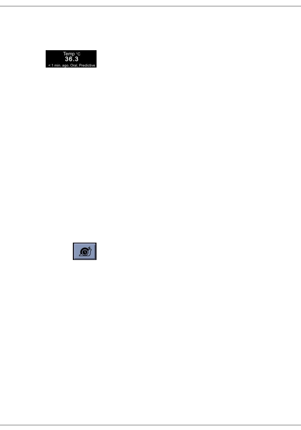
11-4 VC150 Vital Signs Monitor KO00065K
Welch Allyn temperature: Description
Measurement method
Predictive temperature measurement
When a new temperature measurement is initiated, the previous temperature
measurement, if still displayed, will be cleared. When the probe is removed from
the probe well, the temperature measurement starts with a predictive mode that
measures the rate of change in temperature of the probe (with the probe cover)
upon coming into contact with the patient's tissues. SureTemp® Plus
temperature calculates a final temperature by extrapolating a terminal
temperature from the measured warming rate without the need to wait for the
probe tip to warm up to the patient's tissue temperature. The final temperature
is stored in patient data.
The predictive temperature measurement ends when one of the following
occurs:
• A final value is determined.
• The probe is inserted into the probe well.
If predictive measurement is not successful, the monitor will display the Temp
No Determination alarm message. Select the snail icon to start monitor mode
and to display real-time measurement data.
NOTE
The monitor will sound two beeps when a snapshot is automatically created
after a measurement is completed and display the temperature value for a
period defined in Monitor Setup > Advanced > Default Setup > General/
Measurement Expiration Time.
Temperature measurement in monitoring mode
When the predictive measurement is complete, a snail icon appears next to the
temperature figure on the monitor. Select the snail icon to switch to monitor
mode, which measures the temperature continuously and displays it on the
monitor screen. When the monitor mode is selected, the snail icon will be
animated during the measurement.
It is recommended to hold the probe in place for at least 3 minutes (for oral and
rectal) or 5 minutes (for axillary) to ensure that the probe tip has warmed up to
the temperature of the surrounding tissues, giving a valid reading. The tip of the
temperature probe continuously measures the temperature, but does not store
it automatically. When the probe is properly positioned, and the temperature
has stabilized, select Snapshot to create a snapshot with the monitor
temperature measurement.
A monitor temperature measurement ends when the probe is inserted into the
probe well. Monitor mode is not intended for long-term monitoring of patient's
temperature; rather it is intended to produce a spot-check of the patient's
temperature in cases where the predictive algorithm is unable to produce a
result.
NOTE
Long-term continuous monitoring is not recommended in any mode. The
monitor mode is automatically terminated after 10 minutes of monitoring.
KO00065K VC150 Vital Signs Monitor 11-5
Welch Allyn temperature: Welch Allyn temperature measurement
Temperature probes
The temperature probes are color-coded to indicate which probes are used for
oral/axillary or rectal measurement sites.
Refer to the VC150 supplies and accessories document for temperature probe
and probe cover reorder part numbers.
Proper storage of thermometer probe covers
To reduce the risk of contamination, keep the thermometer
probe covers in their original 25-count box and store the
box in the storage well provided on the monitor.
Welch Allyn temperature measurement
NOTES
Do not allow the tip of the temperature probe to come into contact with a
heat source (e.g., hands or fingers) prior to taking a temperature
measurement. If this occurs, allow 5 seconds for the probe tip to cool before
proceeding.
Never insert a probe cover into the probe well.
Oral temperature measurement
1. Ensure that the patient has not done any of the following within 20 minutes
prior to taking a temperature, as these may result in inability to take an
accurate temperature:
• Ingesting hot or cold liquids
•Brushing teeth
•Eating
• Chewing gum or mints
•Smoking
• Activity such as climbing stairs or running
Color-coded temperature probes
Color of the probe ejection button Measurement site
Blue Oral or axillary
Red Rectal
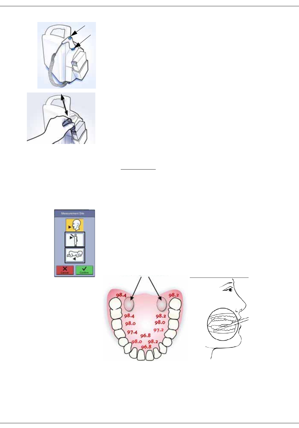
11-6 VC150 Vital Signs Monitor KO00065K
Welch Allyn temperature: Welch Allyn temperature measurement
2. Check that a blue probe well and a probe with a blue ejection button are
connected to the device. If not, obtain a blue probe well and a probe with
the blue ejection button and connect these to the device as instructed in
“Setting up temperature connection” on page 3-4. If these are already
connected, ensure that the probe is in the probe well.
3. Always place a new transparent protective temperature probe cover on the
probe before every oral measurement:
• Remove the probe from the probe well.
• Insert the probe shaft into a probe cover and firmly press down until
retaining rings of the probe cover seat securely over the retaining ring
barb of the probe shaft.
4. Verify that the probe cover fits snugly.
NOTE
Failure to firmly install the probe cover may result in the probe cover
becoming loose or disengaged during use. Unintended probe cover
ejection can lead to patient injury.
CAUTIONS
Injury may occur as a result of patient movement during the procedure.
Do not insert the probe cover into the probe well.
5. Select the temperature parameter to activate a shortcut to the Monitor
Setup > Temperature screen.
6. Select Measurement Site. Check that the temperature area displays Oral. If
this is not displayed, reselect the measurement site.
7. Have the patient open his/her mouth and carefully insert the probe tip deep
under the tongue in the right or left sublingual pocket. Temperatures in
other locations in the mouth can vary by more than 1° C or 2° F. Do not hand
the probe to the patient to place in his or her own mouth. Have the patient
close his or her lips over the probe.
Adult
Pediatric
axillary
axillary
Oral
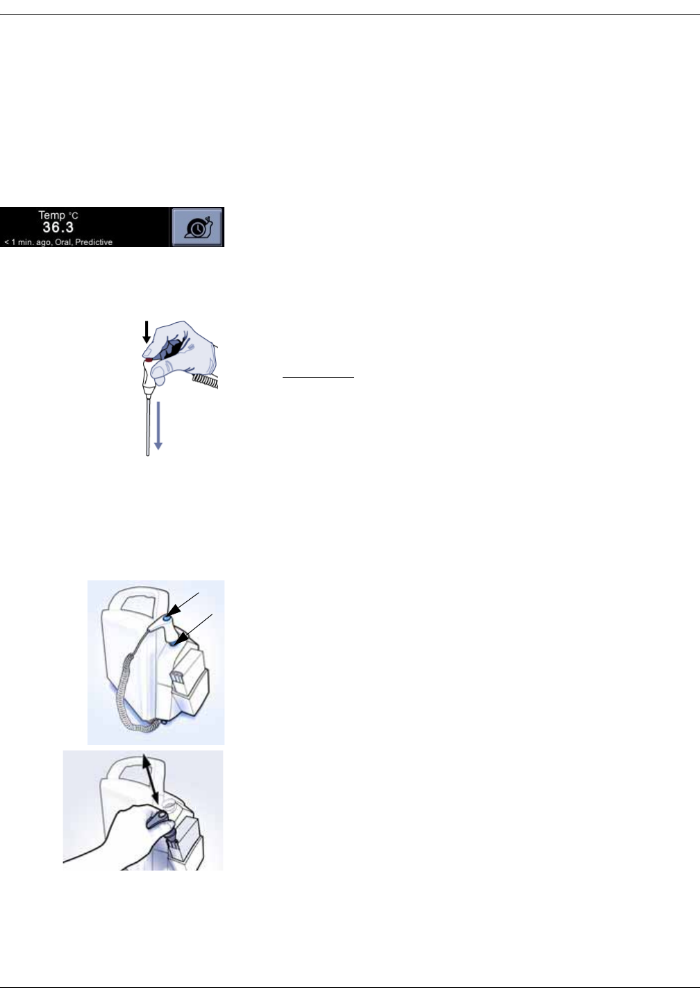
KO00065K VC150 Vital Signs Monitor 11-7
Welch Allyn temperature: Welch Allyn temperature measurement
NOTES
Do not insert the probe cover into the probe well.
Do not allow the probe tip to come into contact with the patient until the
probe is placed in the measurement site. Before this, any contact
between the probe tip and the tissue or other material may cause
inaccurate readings.
8. Always hold the probe in place, maintaining tissue contact until temperature
is complete. Do not allow the patient to reposition the probe.
9. When the predictive measurement is complete, the result is captured to
patient data automatically. If you question a reading, select the snail icon to
switch to monitor mode.
10. When the monitor mode temperature measurement has stabilized, select
Snapshot to create a snapshot and remove the probe from the patient.
11. Eject the disposable probe cover by firmly pressing the ejection button on
the top of the probe.
CAUTION
To prevent cross-contamination, properly dispose of the probe cover
when the measurement is complete.
12. Place the probe in the probe well. Once you place the probe in the probe
well, the temperature values will be cleared in 1 to 30 minutes, depending
on the measurement expiration time setting.
Axillary temperature measurement
1. Adjust clothing to access the entire axilla. Do not take an axillary
temperature through patient’s clothing. Direct probe cover to skin contact is
required.
2. Check that a blue probe well and a probe with a blue ejection button are
connected to the device. If not, obtain a blue probe well and a probe with
the blue ejection button and connect these to the device as instructed in
“Setting up temperature connection” on page 3-4. If these are already
connected, ensure that the probe is in the probe well.
3. Always place a new transparent protective temperature probe cover on the
probe before every axillary measurement:
• Remove the probe from the probe well.
• Insert the probe shaft into a probe cover and firmly press down until
retaining rings of the probe cover seat securely over the retaining ring
barb of the probe shaft.
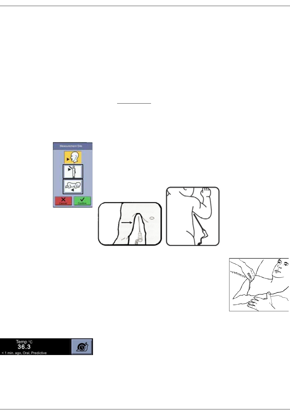
11-8 VC150 Vital Signs Monitor KO00065K
Welch Allyn temperature: Welch Allyn temperature measurement
4. Verify that the probe cover fits snugly.
NOTES
Failure to firmly install the probe cover may result in the probe cover
becoming loose or disengaged during use. Unintended probe cover
ejection can lead to patient injury.
Do not allow the probe tip to come into contact with the patient until the
probe is placed in the measurement site. Before this, any contact
between the probe tip and the tissue or other material may cause
inaccurate readings.
CAUTIONS
Injury may occur as a result of patient movement during the procedure.
Do not insert the probe cover into the probe well.
5. Select the temperature parameter to activate a shortcut to the Monitor
Setup > Temperature screen.
6. Select the adult or pediatric axillary icon on the Measurement Site screen.
7. Avoid folds in the axilla and place the probe tip as high as possible in the
mid-axilla. Left image below is for adults, right image for infants and
children.
8. Insert the probe in the patient's axilla, making
sure the tip of the probe is in contact with the
skin and positioned as close as possible to the
axillary artery.
9. Move the patient’s arm close to the body to seal
off the probe in the armpit. Keep the arm from
moving during the measurement cycle.
10. Always hold the probe in place, maintaining tissue contact until temperature
is complete. Do not allow the patient to reposition the probe.
11. When the predictive measurement is complete, the result is captured to
patient data automatically. If you question a reading, select the snail icon to
switch to monitor mode.
12. When the monitor mode temperature measurement has stabilized, select
Snapshot to create a snapshot and remove the probe from the patient.
Adult
Pediatric
axillary
axillary
Oral
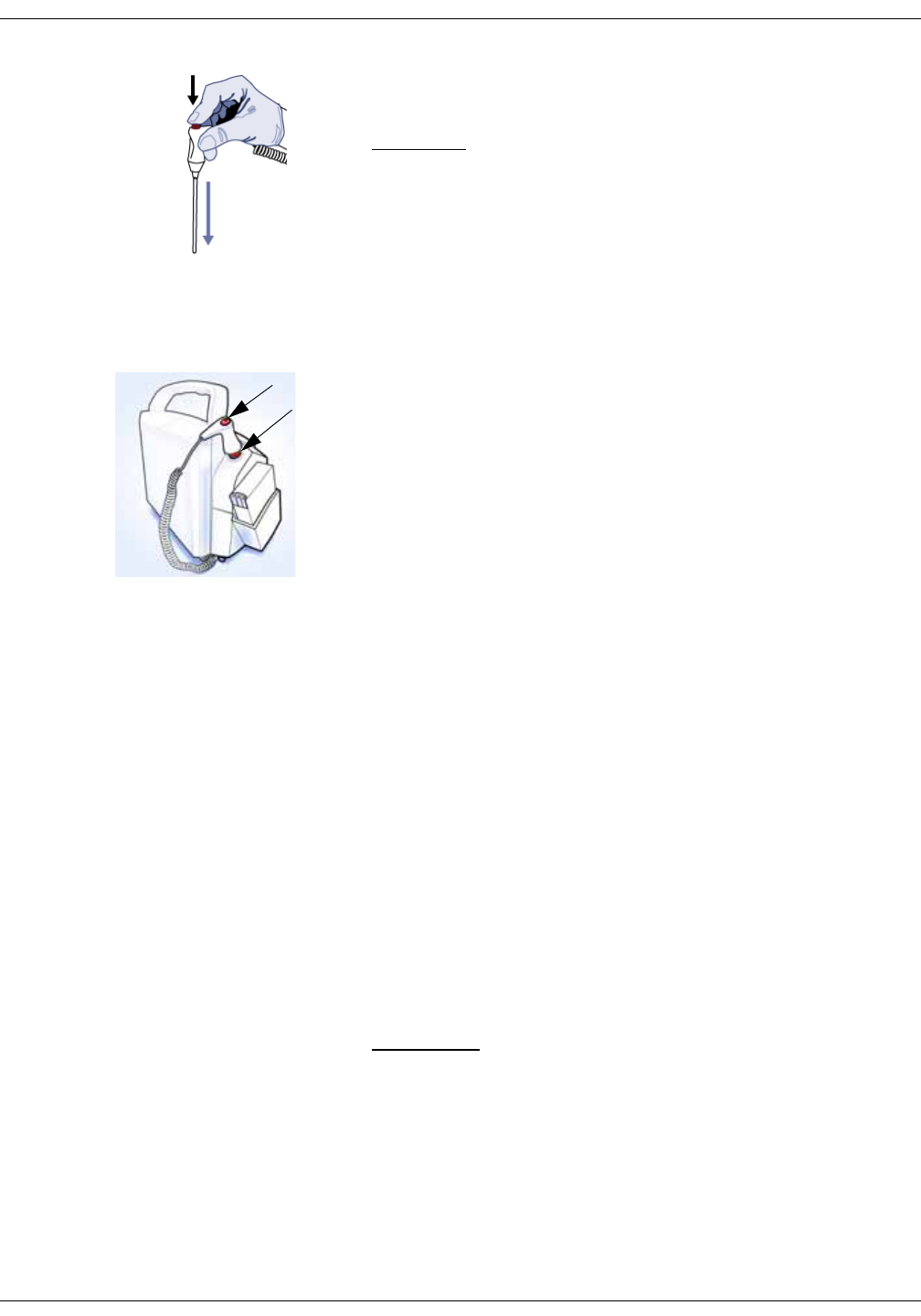
KO00065K VC150 Vital Signs Monitor 11-9
Welch Allyn temperature: Welch Allyn temperature measurement
13. Eject the disposable probe cover by firmly pressing the ejection button on
the top of the probe.
CAUTION
To prevent cross-contamination, properly dispose of the probe cover
when the measurement is complete.
14. Place the probe in the probe well. Once you place the probe in the probe
well, the temperature values will be cleared in 1 to 30 minutes, depending
on the measurement expiration time setting.
Rectal temperature measurement
Use gloves or other measures to reduce the risk of cross-contamination as
appropriate for good clinical practice and/or your institution's infection control
policies.
1. Check that a red probe well and a probe with red ejection button are
connected to the device. If not, obtain a red probe well and a probe with the
red ejection button and connect these to the device as instructed in “Setting
up temperature connection” on page 3-4. If these are already connected,
ensure that the probe is in the probe well.
2. Always place a new transparent protective temperature probe cover on the
probe before every rectal use:
• Remove the probe from the probe well.
• Insert the probe shaft into a probe cover and firmly press down until
retaining rings of the probe cover seat securely over the retaining ring
barb of the probe shaft.
3. Verify that the probe cover fits snugly.
NOTES
Failure to firmly install the probe cover may result in the probe cover
becoming loose or disengaged during use. Unintended probe cover
ejection can lead to patient injury.
Do not insert the probe cover into the probe well.
Do not allow the probe tip to come into contact with the patient until the
probe is placed in the measurement site. Before this, any contact
between the probe tip and the tissue or other material may cause
inaccurate readings.
CAUTIONS
Injury may occur as a result of patient movement during the procedure.
Do not insert the probe cover into the probe well.
4. Select the temperature parameter to activate a shortcut to the Monitor
Setup > Temperature screen.
5. Select Measurement Site. Check that the temperature area displays Rectal.
If this is not displayed, reselect the measurement site.
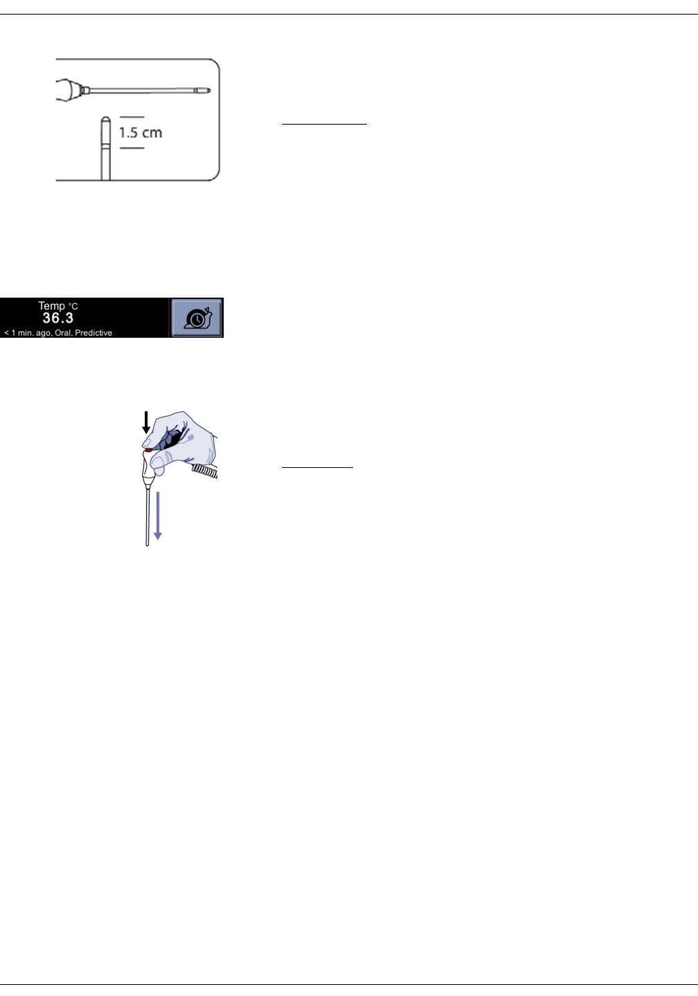
11-10 VC150 Vital Signs Monitor KO00065K
Welch Allyn temperature: Welch Allyn temperature calibration and self-checks
6. Separate the buttocks with one gloved hand and gently insert the probe tip
according to hospital protocol – but no further than 1.5 cm (0.6 inches) for
adults (less for infants and children).
WARNINGS
If the tip is inserted too far, patient tissue damage may occur and the
probe tip may not have good contact with tissue. Use of a lubricant on
the probe cover is optional.
Before performing rectal temperature measurement on neonates and
children, check hospital policy whether it is allowed and with what
conditions.
7. Always hold the probe in place, maintaining tissue contact until temperature
is complete. Do not allow the patient to reposition the probe.
8. When the predictive measurement is complete, the result is captured to
patient data automatically. If you question a reading, select the snail icon to
switch to monitor mode.
9. When the monitor mode temperature measurement has stabilized, select
Snapshot to create a snapshot and remove the probe from the patient.
10. Eject the disposable probe cover by firmly pressing the ejection button on
the top of the probe. Then remove gloves.
CAUTION
To prevent cross-contamination, properly dispose of the probe cover
and gloves when the measurement is complete.
11. Place the probe in the probe well. Once you place the probe in the probe
well, the temperature values will be cleared in 1 to 30 minutes, depending
on the measurement expiration time setting.
Welch Allyn temperature calibration and self-checks
When the monitor is powered on, the monitor automatically calibrates the
temperature circuit to account for ambient room temperature.
NOTE
If large changes occur in the ambient temperature, the temperature system
displays a technical error message. Turn the unit power off and on again.
Note that the patient will be discharged and non-default settings cleared
when the monitor is turned off. If the unit is not turned off after this
temperature error message, the temperature measurement may not be
accurate.

KO00065K VC150 Vital Signs Monitor 11-11
Welch Allyn temperature: Welch Allyn temperature specifications
Welch Allyn temperature specifications
Patent information
Welch Allyn patents
For patent information, please visit www.welchallyn.com/patents
Units of measure °Celsius (C) or °Fahrenheit (F)
Patient temperature Minimum: 26.7° C (80.0° F)
Maximum: 43.3° C (110.0° F)
Monitor mode accuracy ±0.1° C; ±0.2° F
(when tested in a calibrated liquid bath in monitor mode or with a
blackbody calibration tester); meets ASTM E1112, Table 1, in range
specified)
NOTE
If large changes occur in the ambient temperature, the temperature
system can be recalibrated by cycling the monitor’s power using the On/
Off button.
Temperature measurement time
Oral
Adult axillary (18 years and older)
Pediatric axillary (17 years and younger)
Rectal
Times are approximations only.
Approx. 4 -6 sec
Approx. 12 - 15 sec
Approx. 10 -13 sec
Approx. 10 -13 sec
NOTE
Use only Welch Allyn probe covers on the Welch Allyn temperature probes. The size, shape, and thermal
characteristics of the probe covers can affect the performance of the probe. Inaccurate readings or retention
problems may occur unless Welch Allyn temperature probes and Welch Allyn probe covers are used. Refer to the
VC150 supplies and accessories document for reorder part numbers.

11-12 VC150 Vital Signs Monitor KO00065K
Welch Allyn temperature: Troubleshooting
Troubleshooting
Problem Cause Solution
Temperature
readings are lower
than expected or
reading is not
obtained.
• The measurement may be
affected by external influences.
• The probe may not be in
consistent tissue contact.
• The probe may be incorrectly
positioned.
• Incorrect probe covers are used.
• The axillary position of the probe
may be too low to obtain a
predictive measurement or the
probe tip may be exposed to air
through the back of the axilla.
• Eliminate external influences caused by ambient
air temperature or the intake of any liquids or
physical matter by mouth before taking a
measurement.
• Verify the temperature probe is correctly
positioned for the site being measured:
• Oral measurement: Place the thermometer tip
in either the right or left sublingual pocket
(heat pocket) at the base of the tongue. Have
the patient close his or her lips over the probe.
Continue to hold the probe in place, as
motionless as possible until the final reading
is obtained.
• Axillary measurement: Insert the probe in the
patient's axilla, making sure the tip of the
probe is in contact with the skin and
positioned as close as possible to the axillary
artery with the patient's arm held close to his/
her side.
• Rectal measurement: Insert the probe, using
current hospital technique for penetration.
• Use Welch Allyn oral/axillary or rectal probe
covers on the Welch Allyn temperature probe.
Refer to the VC150 supplies and accessories
document for reorder part numbers.
Repeated error
messages appear
when taking a
rectal temperature.
• The lubricant applied to the
probe cover is too thick, reducing
the heat transfer from the
patient to the probe.
• The lubricant is too cool.
• The probe may not be in
consistent tissue contact.
• Do not over-apply lubricant to the probe.
• Allow the lubricant to warm to room temperature
before application to the probe cover.
• To take an accurate rectal temperature reading,
insert the probe tip according to hospital protocol
– but no further than 1.5 cm (0.6 inches) for adults,
less for pediatric patients. If the tip is inserted too
far, damage may occur and the probe tip may not
have good contact with tissue.

KO00065K VC150 Vital Signs Monitor 11-13
Welch Allyn temperature: Cleaning
Cleaning
Refer to “Cleaning” on page B-4 for instructions for cleaning and disinfecting
Welch Allyn device and its accessories.
Temperature
readings do not
register on
hypothermic
patients.
Wait until the predictive
measurement is complete. Then
switch manually to monitor mode.
Allow the temperature values to
stabilize before recording the
temperature. It will continue to
monitor the patient’s temperature
until the probe is removed from the
patient (the temperature reading will
change as soon as the probe is
removed from the patient; record the
temperature displayed at the
prescribed time before removing the
probe from the patient).
The monitor does not beep to indicate a final reading.
Leave the probe in place for the same length of time as
required by standard hospital procedure for taking a
continuous (monitor) temperature measurement.
Problem Cause Solution

11-14 VC150 Vital Signs Monitor KO00065K
Welch Allyn temperature: Cleaning
This page is intentionally left blank.

KO00065K VC150 Vital Signs Monitor 12-1
12 Exergen temperature
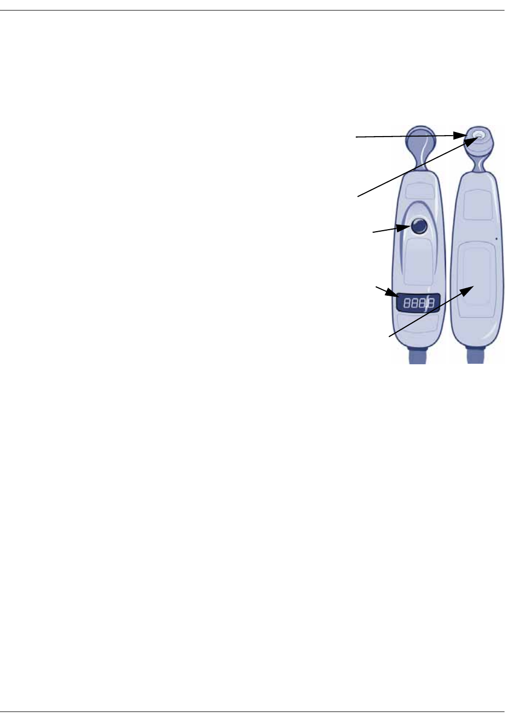
12-2 VC150 Vital Signs Monitor KO00065K
Exergen temperature: Description
Description
The monitor can use the Exergen Temporalscanner technology if it has the
Exergen temperature parameter (temperature parameter displayed on the
screen and Exergen connected to the monitor USB port).
Temporalscanner technology
provides a method of temperature
assessment based on infrared
measurement of the thermal
radiation of the skin. The temporal
artery is used as a sampling site
because of its relatively constant
perfusion rate. While the scanner
senses temperature from the area
of the temporal artery, it can
optionally report temperature
readings referenced to either
central arterial temperature or oral
temperature.
Temperature values are shown in
degrees Celsius or Fahrenheit on
the monitor screen and on the
scanner’s LED display screen. The
LED display screen displays the
temperature, but does not display
the unit of measurement.
The preset unit of temperature measurement on the monitor screen and the
Exergen LED display can be changed by service personnel only.
NOTES
Arterial temperature is close to rectal temperature, approximately 0.4° C
(0.8º F) higher than oral temps. Expect larger differences at times, however,
as the dynamics of thermoregulation favor the temporal artery method.
Arterial temperature is the same temperature as the blood flowing from the
heart via the pulmonary artery. It is the best determinant of body
temperature, and unaffected by the artifactual errors and time delays
present with oral and rectal methods.
The scanner takes a single instance of a temperature measurement.
Exergen technology does not support continuous monitoring.
A monitor with the Exergen temperature technology configuration setting
cannot perform Welch Allyn temperature measurements and vice versa.
Use this product only for its intended use as described in this manual.
Do not take temperature over scar tissue, open sores, or abrasions.
The thermometer is not shockproof. Do not drop it or expose it to electrical
shocks.
Do not autoclave. Please note cleaning and sterilizing procedures in this
manual.
Probe
cone
On button
LED display
screen
Probe
lens
Battery
compartment

KO00065K VC150 Vital Signs Monitor 12-3
Exergen temperature: Description
NOTES
Do not use the thermometer if it is not working properly, if it has been
exposed to temperature extremes, damaged, been subject to electrical
shocks or immersed in water.
There are no parts that you can service yourself except for the battery,
which you should replace when low by following the instructions in this
manual. For service, repair, or adjustments, return your thermometer to
Innokas Medical.
Never drop or insert any object into any opening, except for opening the
battery cover as described in this manual.
The VC150 monitor can be used with two Exergen thermometer options:
• Oral calibration
• Arterial calibration
One version has been calibrated to report measurements referenced to core
arterial blood temperature, while the other is calibrated to report measurements
referenced to oral equivalent temperature.
Temperature measurement mode
Upon initiation of a measurement, the previous temperature measurement, if
present, is cleared. A measurement is initiated when the user presses the On
button on the scanner. The Temperature window on the monitor remains blank
while a measurement is in progress. In measurement mode, a final temperature
is displayed and an audible double tone sounds.
A measurement is terminated when one of the following occurs:
• The user releases the On button and final value is determined.
• A technical alarm is issued.
WARNINGS
Keep accessories out of patient's reach when not in use.
Do not allow the scanner to come into contact with open wounds or
mucous membranes.
Keep the temperature scanner secured when it is not in use.
NOTES
Connect only one integrated Exergen TAT-5000S-USB scanner to the
monitor.
If the Exergen scanner is not used regularly, remove the battery to prevent
possible damage due to chemical leakage.
The scanner will issue an error code if a temperature determination is not
possible, and the monitor will also indicate an error in the temperature
window. In addition, at temperatures between 16.1° C and 26.7° C (61° F and
80° F), the scanner will display a value, and the monitor will indicate the
value is out of range with a ‘----’ in the temperature window.

12-4 VC150 Vital Signs Monitor KO00065K
Exergen temperature: Procedures for temperature determination
Additional indicators
If the scanner is unable to take a temperature determination or has a low
battery, the monitor will display a technical alarm on the monitor screen. Refer
to “Technical alarm conditions” on page 4-10 for additional indicators on the
scanner’s LED window.
Sounds
There are three sounds associated with the Exergen temporal scanner
parameter.
• Single tone: sounds upon detection of a temperature status alarm
regardless of the state of alarm silence.
• Double tone: sounds at the completion of a temperature measurement that
results in a final value.
• Audible selecting tone: Each fast click tone indicates a rise to a higher
temperature. A slow selecting tone indicates that the scanner is still
scanning, but not finding any higher temperature.
The VC150 will sound two beeps when a snapshot is automatically created after
completion of a measurement.
Procedures for temperature determination
Familiarize yourself with the scanner
• To scan: Press and hold the On button. The scanner will continually scan for
the highest temperature (peak) as long as the button is pressed.
NOTE
Be aware that if you accidentally press and release the On button
without applying the scanner to a patient’s forehead, the scanner will
include this erroneous ambient room temperature value in patient data.
• To view the displayed temperature value: After taking a temperature
measurement, the temperature value will remain on the scanner display for
30 seconds after button is released. If measuring room temperature, the
temperature value will remain on the scanner display for 30 seconds.
• To restart: Press the On button to restart. It is not necessary to wait until the
display is clear. The thermometer will immediately begin a new scan each
time the button is selected.
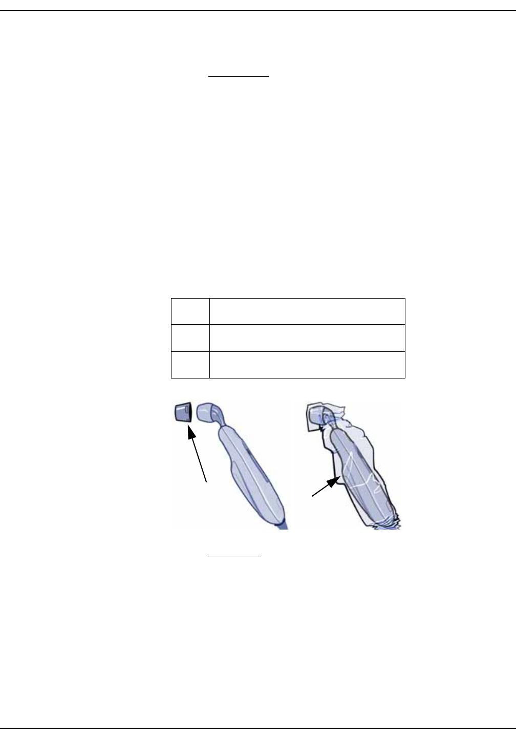
KO00065K VC150 Vital Signs Monitor 12-5
Exergen temperature: Procedures for temperature determination
Basics of using the temporal scanner
CAUTIONS
To prevent cross-contamination between patients, apply a fresh
disposable cap on the probe or clean the Exergen between patients as
instructed in “Cleaning the Exergen probe head and neck” on page B-6.
1. Confirm the temporal scanner is connected to the monitor. Refer to
“Connecting USB accessories” on page 3-6 for more information.
NOTE
Be careful not to overextend the coiled cord of the scanner.
Overextension can damage the scanner coil connector interfaces.
2. If needed, place a disposable cap over the probe head or a protective
sheath over the entire scanner. Be sure to inspect the protective cover or
sheath before every use to make sure the cover or sheath is defect free,
contamination free, and installed properly with a snug fit. When using a
protective disposable cap or sheath, always use a new protective cover or
sheath when taking a measurement on a different patient.
CAUTION
Patient movement during temperature measurement may result in
patient injury.
3. Brush patient’s hair aside if covering the temporal artery area or the ear
area.
Item Name
1 Protective disposable cap
2 Protective sheath
1
2
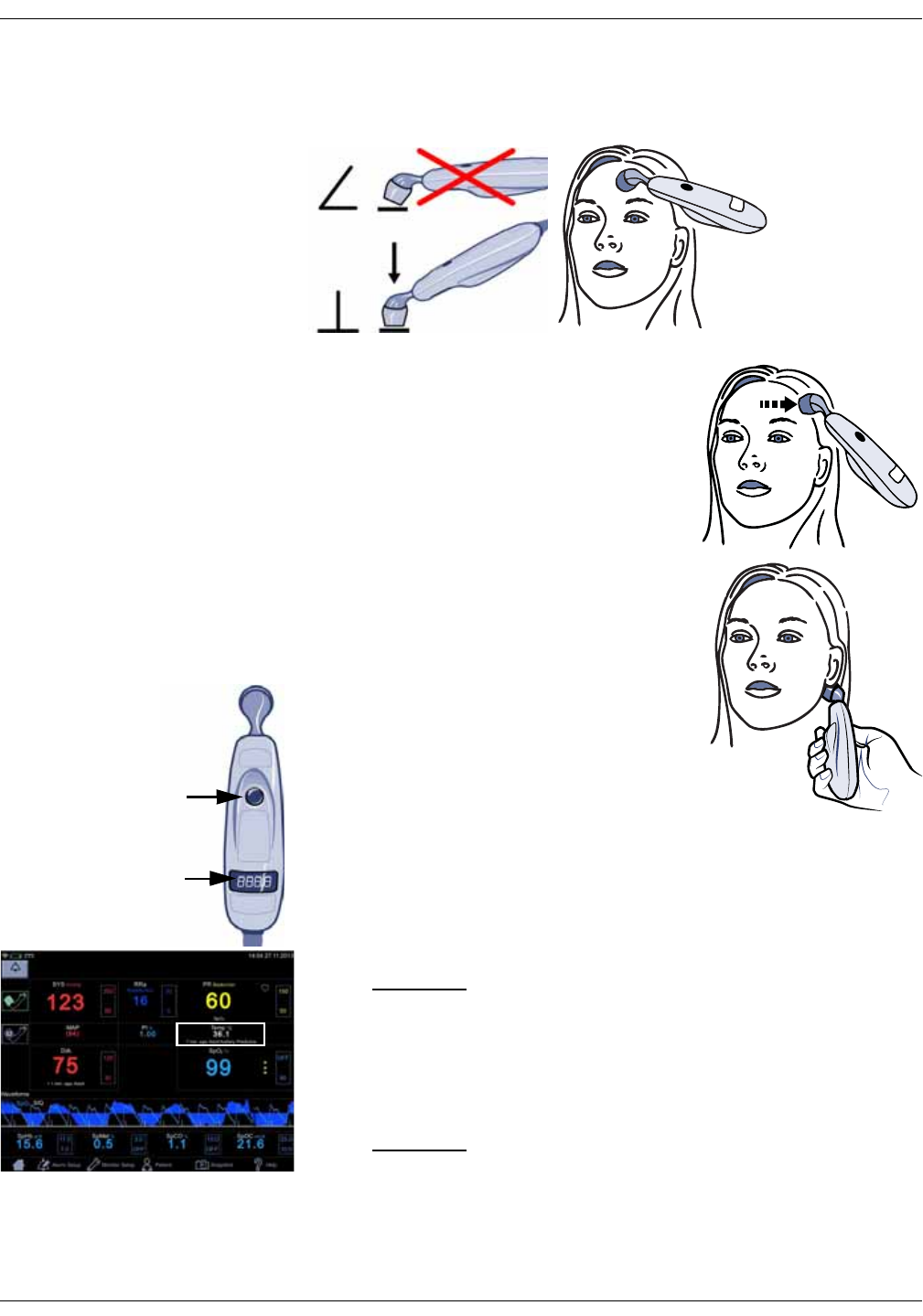
12-6 VC150 Vital Signs Monitor KO00065K
Exergen temperature: Procedures for temperature determination
4. Gently place the scanner on the center of forehead, press and hold down
the On button on the scanner. Keep the scanner head in flush contact with
the skin while sliding.
5. While still pressing the On button, slide the
scanner slowly and gently straight across
forehead to the patient’s hair line, not down
on the cheek.
6. Brush patient’s hair away if covering ear.
Keeping the button selected, lift probe from
forehead, gently touch behind ear halfway
down the mastoid process and slide down to
the soft impression behind the earlobe.
7. Release the On button and read the
temperature. When the determination is
complete, an audible double tone sounds
and the temperature displays on the
scanner’s LED display screen and on the
monitor. The reading will remain on LED
display screen of the scanner for 30 seconds
after the button is released. The reading will remain on the monitor’s display
for 1 to 30 minutes, depending on the monitor configuration.
8. If you placed a protective disposable cap or scanner sheath on the scanner,
dispose of the protective disposable cap or scanner sheath according to the
applicable waste control regulations of your facility.
CAUTION
To prevent cross-contamination, properly dispose of the disposable cap
when done with its use.
9. Clean the Exergen scanner as instructed in “Cleaning the Exergen sensor
lens” on page B-6.
CAUTION
Failure to clean the scanner between patients may increase the risk of
cross-contamination.

KO00065K VC150 Vital Signs Monitor 12-7
Exergen temperature: Exergen temperature specifications
Exergen temperature specifications
Exergen scanner battery specifications
Units of measure °Celsius (C) or °Fahrenheit (F). Defined by purchased Exergen scanner.
Range
Measurement mode Max: 43° C (110° F)
Min.: 16° C (61° F)
Accuracy ±0.1° C (±0.2° F)
complies with EN 12470-5
Predictive mode Not applicable
Monitoring mode Not applicable
Operating environment (ambient) 16° to 40° C (61° to 104° F)
Arterial head balance range for body
temperature1
34.5° to 43° C (94° to 110° F)
Resolution 0.1° C or 0.1° F
Response time Approximately 0.04 seconds, typical
Calibration Oral or Core
1 Automatically applied when temperature is within normal body temperature range, otherwise reads surface
temperature.
NOTE
Use only Exergen probe covers. The size and shape of the probe covers can affect the performance of the
scanner. Inaccurate readings occur unless the proper probe covers are used. Refer to the VC150 supplies and
accessories document for reorder part numbers.
Capacity One 9 volt alkaline
Battery life Approx. 15,000 readings
(When scanning for 5 seconds and reading the temperature display for 2
seconds before turning thermometer off.)

12-8 VC150 Vital Signs Monitor KO00065K
Exergen temperature: Patent information
Patent information
Exergen patents
For patent information, please visit www.exergen.com/patents
Troubleshooting
Problem Cause Solution
Unable to take a
measurement from
the patient’s
forehead.
The patient has bandages or
pressure dressings covering the
forehead or abrasions, burns, or
sweat on the forehead.
Use alternate measurement sites:
• If accessible and dry, measure on the area behind
the earlobe only.
• If the temporal artery (TA) area has been
traumatized by burns or lacerations, is
completely covered with dressings, or the
head has suffered surgical or accidental
trauma, the temperature can be obtained
from the alternative site behind the earlobe.
As with diaphoresis, the perfusion will be high
in the presence of head trauma.
• Behind the earlobe is the alternate site
because sweat causes evaporative cooling of
the skin on the forehead and may produce a
false low reading. During diaphoresis, the area
on the head behind the earlobe will always
exhibit the high blood flow necessary for the
arterial measurement.
• Measurement behind the earlobe is not the
sole recommended area because the arterial
branch is deeper behind the earlobe than at
the temple, and under normal conditions it is
less accurate because of its variability. But
under diaphoretic conditions, the blood flow
behind the earlobe is as high as at the TA,
making it as accurate as the TA, but only
during diaphoresis or with head trauma as
previously mentioned.
• If the temporal artery or the area behind the earlobe
is not accessible and dry, choose one of the
following alternate temperature measurement sites:
• Femoral artery: scan across the femoral
artery following the crease in the groin.
• Lateral thoracic artery: slowly scan side-to-
side in the area, midway between the axilla
and the waist. Mainly used for children.

KO00065K VC150 Vital Signs Monitor 12-9
Exergen temperature: Troubleshooting
Unable to get an
accurate
measurement.
The patient is agitated or combative. Consider using the alternate sites: femoral artery or
lateral thoracic.
Possible false
reading.
The patient's forehead is in a direct
draft from a vent or fan.
Remove the source of the draft. Each 10° difference in
ambient temperature can cause a 1° error in the
reading.
The thermometer is in a different
ambient temperature than patient
(e.g., window ledge directly exposed
to hot sun or cold weather, or in
direct line of air conditioning or fan).
Store the scanner at the same ambient temperature
as the patient for at least 20 minutes before taking a
temperature measurement. Each 10° difference in
ambient temperature can cause a 1° error in the
reading.
Scanner readings
are not
comparable to
current/traditional
methods.
Arterial temperature is close to rectal
temperature, approximately 0.4° C
(0.8º F) higher than oral temps.
Expect larger differences at times, as the dynamics of
thermoregulation favor the temporal artery method.
Scanner readings
are lower than
current/traditional
methods; false low
readings.
• A patient's temperature measured
with the scanner is normally not
appreciably lower than oral
temperature. Lower temperatures
are usually caused by improper
scanning techniques.
• A dirty scanner lens may result in
inaccurate measurement
determinations.
• Both a sweaty forehead and wet
behind ear.
• Multiple readings can cool the skin,
so if you take another
measurement immediately, expect
a slightly lower reading.
• The button was released before
the measurement was complete.
• Slide the scanner
straight across the
forehead, not down
the side of the face.
Do not scan too
quickly.
• Keep the probe cone
flush on the skin.
• Clean the lens.
• Return when patient
stops sweating.
• Keep the button
pressed down while
scanning.
• Refer to “Basics of
using the temporal scanner” on page 12-5 for user
instructions.
The measurement
appears on the
scanner window,
but does not
register in the
monitor.
• The scanner’s connector is not
secured to the monitor.
• The scanner’s battery cover is not
secured.
• Loss of electrical contact between
the scanner and the monitor (e.g.,
corrosion on the connector inside
the scanner).
• The monitor is not configured to
interface with an Exergen scanner.
• Confirm the scanner’s connector is secured to the
monitor.
• Confirm the scanner’s battery cover is secured.
•Contact service.
Problem Cause Solution

12-10 VC150 Vital Signs Monitor KO00065K
Exergen temperature: Batteries
Batteries
Refer to “Maintenance” on page B-1 for details on storage, care, replacement,
and disposal of batteries for the monitor and the Exergen temporal scanner.
Cleaning
Refer to “Cleaning” on page B-4” for details on cleaning and disinfecting the
Exergen temporal scanner.
Scanner readings
are higher than
current/traditional
methods; false high
readings.
• The forehead is covered during a
temperature measurement.
• Temperatures measured with
the scanner may be higher than
your current method, especially
if you are familiar with oral or
axillary temperatures.
• Any covering, hair, hat, bandages, etc., would
prevent the heat from dissipating, causing the
reading to be falsely high. Only measure skin that
is exposed to the environment.
• Oral and axillary temperatures can be
misleadingly lowered due to patient activity such
as mouth breathing, drinking, tachypnea,
coughing, talking, etc., and periods of
vasoconstriction during the fever process. Any or
all of these conditions may even mask fevers that
the scanner will detect.
Problem Cause Solution

KO00065K VC150 Vital Signs Monitor 13-1
13 Battery
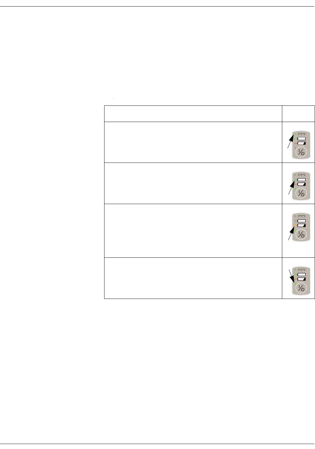
13-2 VC150 Vital Signs Monitor KO00065K
Battery: Description
Description
The monitor uses a rechargeable Lithium-ion (Li-Ion) battery that consists of Li-
Ion cells that can be charged at any time without reducing its charge capacity.
The battery reports its condition to the monitor and this is displayed by battery
indicators on the monitor screen. The monitor is designed to always derive its
power solely from the battery; and the battery is being charged whenever the
external DC charger is connected (refer to “Product specifications” on page 2-
19).
NOTES
• Due to moisture condensation risk, the monitor has to warm up to room
temperature after transportation or storage.
• Only trained and authorized service person may uninstall and install the
battery. The monitor cannot be used before the battery is installed.
• The monitor is designed to operate only when the battery is installed in the
monitor.
• When the monitor’s battery has been completely discharged, the monitor
must be connected to an external power supply before monitoring can
resume.
• Service must unplug the battery before transport or storage.
Description LED
Connected to mains. When a green LED is:
• On: Power cable is connected to mains
• Off: The power cable is disconnected
Battery OK. When power LED is:
• On: Battery full
• Blinking (every 2 seconds): Battery charging
• Off: No battery / Low charge
Low battery. When orange LED is:
•Off: OK state
• On: Charge remaining for at least 10 NIBP measurements.
• Blinking fast (every 0.2 seconds): Battery error / No battery
• Blinking slow (every second): Battery charge for 5 minutes or
less of unit operation time remaining
State of operation. When a green LED is:
• On: The monitor is switched on
•Off: The monitor is switched off
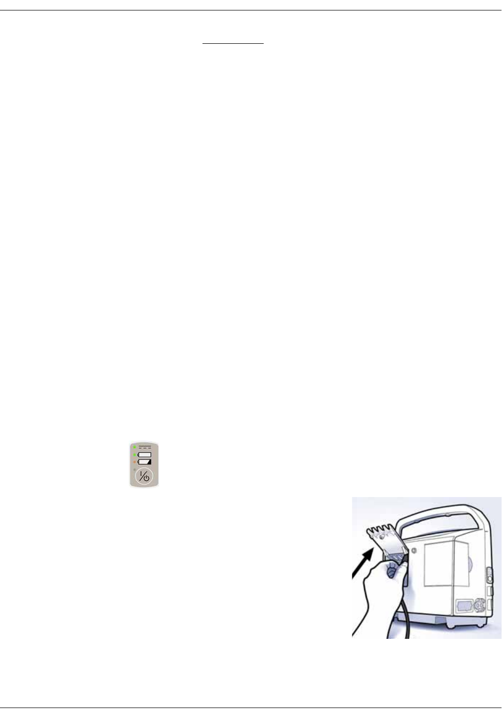
KO00065K VC150 Vital Signs Monitor 13-3
Battery: Battery charging
WARNINGS
Use only a battery type that has been specified for this monitor. Do not
use a damaged or leaking battery. Other batteries may not provide the
same operating time and may cause unexpected monitor shutdown.
Other batteries may be incompatible with the internal charger and may
cause battery acid leakage, fire, or explosion.
Do not disassemble, modify, crush or destroy the battery pack. Doing so
can cause battery fluid leakage, heat generation, burns, fire, and/or
explosion.
Do not incinerate the battery or store at high temperatures. Doing so
may cause the battery to explode.
Do not short-circuit the battery terminals by directly connecting the
metal terminals together. Be certain that no metal objects (e.g., coins,
paper clips, etc.) touch both battery terminals simultaneously. Doing so
can cause the battery to overheat and/or explode, resulting in possible
caustic burns and/or battery damage.
Charge the battery pack with the monitor's internal charger only. Use of
an unrecommended charger may cause battery fluid leakage,
overheating of the battery, or may cause the battery to explode.
The battery will completely discharge if the monitor is stored for a
prolonged period of time with the battery left inside and not periodically
recharged. Configuration settings may be lost as a result.
Battery charging
Prior to each use, inspect the power cord to ensure proper connection and
condition.
With external DC power connected, the battery charge icon and an LED on the
power on/off button indicate that the battery is charging. This indicator remains
active whether the unit is on or off. A tone sounds whenever the DC charger is
connected/disconnected.
Battery charging will take place as long as
the monitor remains connected to an
external DC power source.
• Charge the battery pack for 8 hours
before first use or after prolonged
periods of storage.
• If the monitor is idle for extended
periods, it should be fully charged at
least once a week to ensure optimum
performance. If the monitor is to be
stored for longer than one month, first
charge the battery and then have
service to unplug the battery connector.
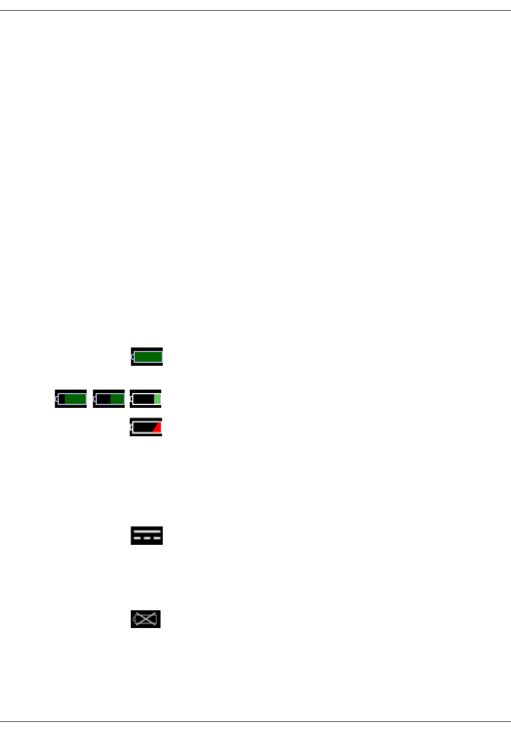
13-4 VC150 Vital Signs Monitor KO00065K
Battery: Battery charge level
• The battery pack should be charged before use, because a charged battery
loses charge when left in storage. Charging is done automatically by the
monitor when the external DC power is connected.
• The battery pack should be charged at room temperature, 5° C to 40° C
(41° F to 104° F).
• You can charge the battery pack at any time. You should not wait until
battery is fully discharged.
• Keep the monitor connected to a DC power supply whenever possible. Do
not allow the battery to become completely discharged.
• Keep the monitor plugged in when not in use to ensure maximal battery
charge.
• A fully charged battery will power the monitor for up to 8 hours in a heavy-
use scenario and up to 11 hours in a light-use scenario (refer to “Monitor
battery specifications” on page 13-6 for details). If the monitor is being used
very intensely, the operation time may be less than mentioned before.
• To ensure full charge cycles, replace only with a recommended battery.
• Replace the battery every three years. If the monitor displays a low battery
soon after charging or is unable maintain charge, contact service for
battery replacement.
Battery charge level
When the monitor is not connected to an external power supply and a green
battery indicator is displayed on the screen, the battery is fully or sufficiently
charged to perform 11 or more NIBP measurements.
The green battery indicator displays the remaining power as a percentage.
A red battery indicator and low priority battery alarm message on screen mean
that the battery is running out and the monitor may perform approximately 10
NIBP measurements. Use of the printer should be avoided. When there are five
minutes of monitor operation time available, both a red battery indicator and a
high priority battery alarm message are displayed on the screen. The battery
power level is low and the monitor must be connected to an external power
supply. Printing and NIBP measurements are no longer possible, but network
communication is still possible.
When the monitor is connected to the mains and the battery is charging, a
animated battery charge indicator is displayed on the information area of the
screen. The battery will be charged in about 8 hours if the monitor is being used
at the same time. If the monitor power is off, the battery will be charged in about
4 hours. Each time the monitor is connected to or disconnected from mains, an
audible signal sounds.
If the monitor is turned on without an installed battery, a missing battery
indicator is displayed on the screen and the monitor will not allow any operation.
If the battery becomes faulty during operation, a missing battery indicator is
displayed on the screen. If this icon appears on the screen, the monitor must not
be disconnected from an external power supply.
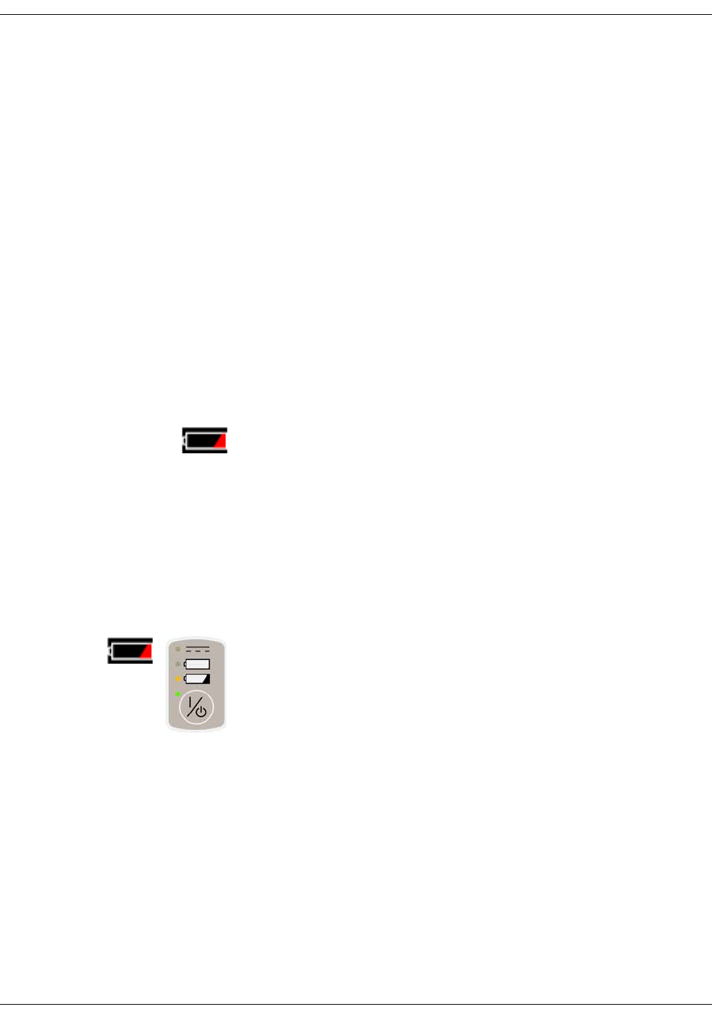
KO00065K VC150 Vital Signs Monitor 13-5
Battery: Storage, care, and replacement of batteries
Storage, care, and replacement of batteries
Refer to “Maintenance” on page B-1 for details on storage, care, and
replacement of batteries for the monitor and the Exergen temporal scanner.
Disposal of batteries
Refer to “Maintenance” on page B-1 for details on disposal of batteries for the
monitor and the Exergen temporal scanner.
Battery alarms
Battery low
When battery charge for at least 10 NIBP measurements remains:
• Battery icon will change to red when low priority battery alarm is triggered.
• The monitor continues to operate normally.
• A low priority alarm is displayed.
• An orange LED is displayed above the On/Off-button.
NOTE
It is strongly recommended that you plug the monitor into external DC
power when the low battery alarm is active.
When battery charge for about 5 minutes or less of unit operation time remains:
• A red battery indicator is displayed on the screen and an orange LED above
On/Off-button starts to blink slowly.
• A high priority alarm message is displayed.
• The user is not able to initiate:
• any new NIBP determinations of any type
•any printouts
NOTE
Monitor cannot be restarted when battery charge is critically low. This
means that if a high priority Low battery alarm is active and monitor is shut
down, it cannot be restarted before the charger is plugged in. This is to
protect the battery pack.

13-6 VC150 Vital Signs Monitor KO00065K
Battery: Monitor battery specifications
Monitor battery specifications
Troubleshooting
This section discusses potential difficulties and suggestions for resolving them. If
the difficulty persists, contact service or your local Innokas Medical
representative. The service manual, which is for use by service personnel,
provides additional troubleshooting information.
Capacity 5.2 Ah Li-Ion battery
Battery run time Up to 11 hours with a usage scenario of:
• NIBP determinations every 15 minutes
•SpO
2 or temperature parameter not active
•WLAN off
Up to 8 hours with a usage scenario of:
• NIBP determination every 5 minutes with an adult cuff
•SpO
2 and temperature parameter actively measuring
•WLAN on
The above battery run times are valid for a new battery and depend
heavily on display brightness settings. After approximately 300 full charge
and discharge cycles, the capacity of the battery is reduced to 70 percent
of its original rating.
Charge time Approximately 4 hours from full discharge when the monitor is off.
Approximately 4 hours when the monitor on.
Problem Cause Solution
The monitor
cannot be turned
on.
• Is the battery missing?
• Is the battery discharged?
• Check that the battery is installed.
• Charge the battery. Refer to “Battery charging” on
page 13-3.
The battery does
not work or does
not last very long.
• Has the battery been charged?
• Has the battery been in storage
or a nonuse condition for a few
months?
• Is the battery installed properly?
• Was the battery over-discharged
when it was last used?
• Battery may be bad.
• New batteries must be charged before use. Refer
to “Battery charging” on page 13-3.
• Bad battery must be replaced. Contact service.

KO00065K VC150 Vital Signs Monitor 13-7
Battery: Troubleshooting
The battery will not
charge.
• Are you trying to charge the
battery in unusually cold or hot
temperatures?
• Charging the battery should be done at a basic
room temperature of 10° C to 35° C (50° F to 95° F).
Slowly bring the battery to the basic room
temperature before charging. Batteries can be
fully charged only when their internal
temperatures are between 5° C to 40° C (41° F to
104° F).
The battery
missing indicator
appears on the
screen.
There is some fault in the battery. • Keep the monitor connected to an external power
supply. All operations of the unit are accessible
except clinical mode.
• Write down the error message.
• Discontinue all measurements and store data in
hospital network.
• Turn the monitor off.
•Contact service.
The battery low
indicators remain
lit.
The battery may be defective and
unable to recharge.
Try to charge the battery again. If unsuccessful,
replace the battery.
Problem Cause Solution

13-8 VC150 Vital Signs Monitor KO00065K
Battery: Troubleshooting
This page is intentionally left blank.

KO00065K VC150 Vital Signs Monitor 14-1
14 Default setup
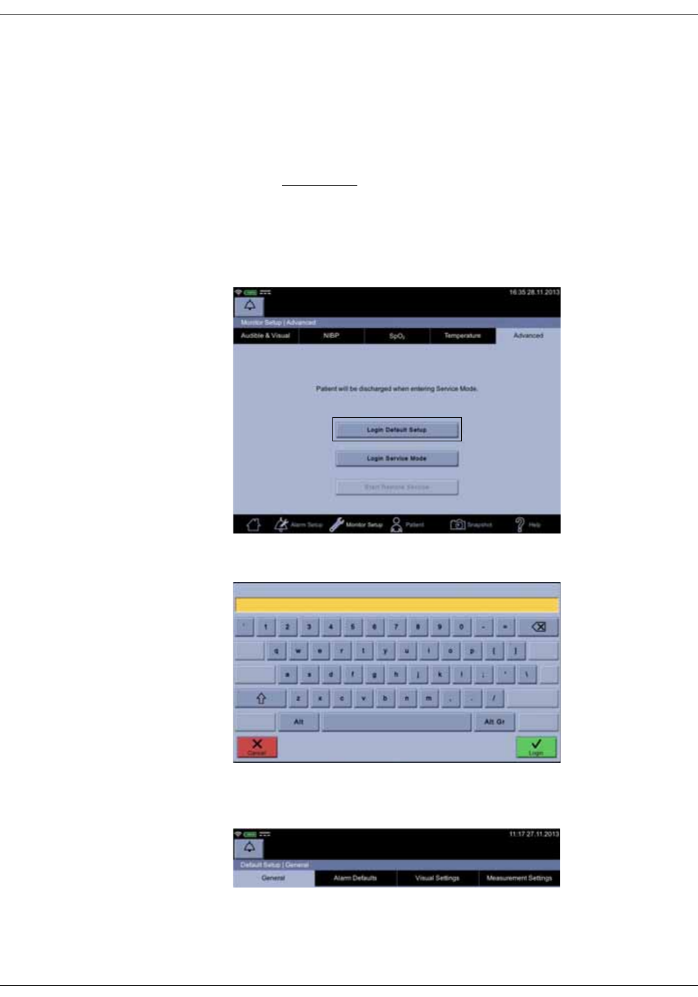
14-2 VC150 Vital Signs Monitor KO00065K
Default setup: Introduction
Introduction
Password-protected Default Setup is intended for someone at the hospital or
care unit that has the training and authority to configure default settings for the
monitor. Obtain the password from service.
WARNING
When you are done with the configuration, remember to press the
home icon to save settings and exit the Default Setup. Failure to do so
allows change of settings by unauthorized users.
1. Select Login Default Setup in the Monitor Setup > Advanced screen.
2. Enter the password and select Confirm.
3. Adjust the settings for General, Alarm Defaults, Visual Settings or
Measurement Settings.
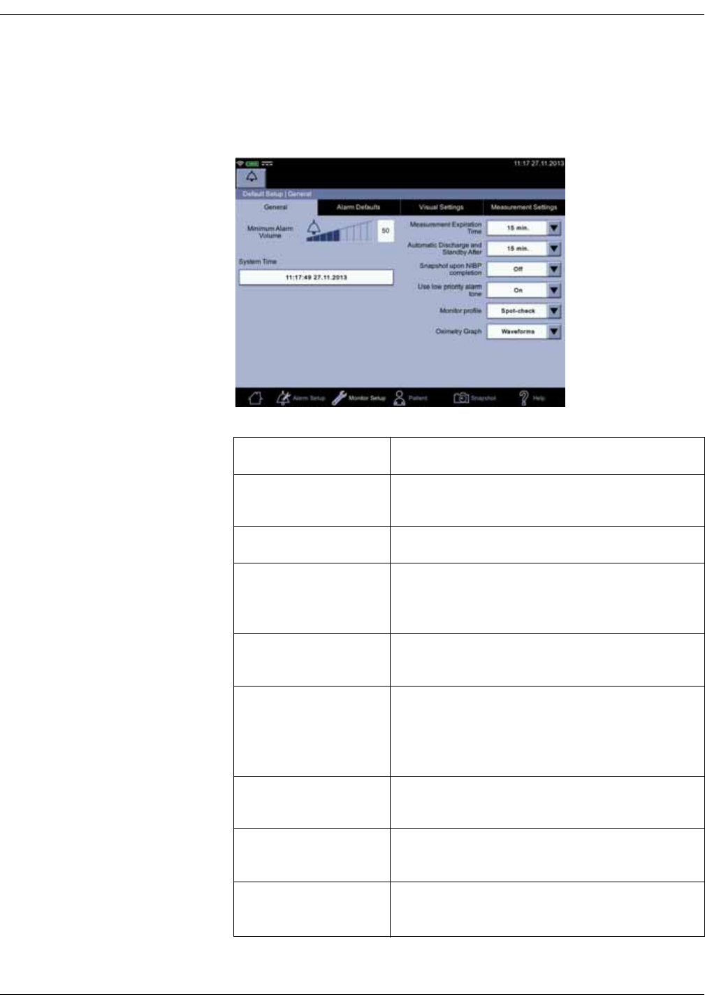
KO00065K VC150 Vital Signs Monitor 14-3
Default setup: Introduction
General
General screen items can be set in Monitor Setup > Advanced > Default Setup
> General. These settings affect all applicable monitor screens. Availability of the
choices may vary due to SpO2 technology and other purchased options.
General settings Description
Minimum Alarm
Volume Minimum level of alarm sound.
System Time Current date and time.
Measurement
Expiration Time
Amount of time for NIBP and temperature
measurement values to remain on screen after the
measurement is completed.
Automatic Discharge
and Standby After Idle period after which the monitor will enter
standby state.
Snapshot upon NIBP
Completion
Current values for SpO2, Welch Allyn temperature
(monitor mode), RR or RRa, and extra parameters
by Masimo SpO2 are stored as a snapshot upon
completion of NIBP determination.
Use low priority alarm
tone Determines whether low priority alarms are
audible.
Monitor Profile Selection for active profile (Spot-check or
Monitoring) upon start-up.
Oximetry Graph Type of graphic presentation of SpO2 data in the
Graph area.
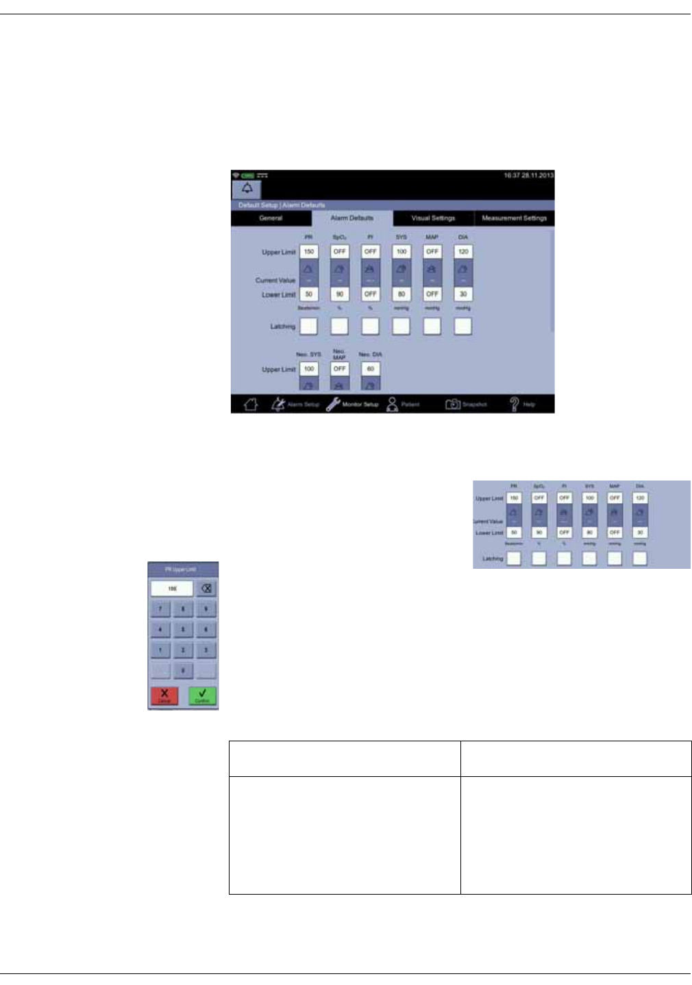
14-4 VC150 Vital Signs Monitor KO00065K
Default setup: Introduction
Alarm defaults
Parameter-specific upper and lower limits may be set up or enabled/disabled in
the Default Setup > Alarm Defaults screen. Limits set here will remain even if
the monitor is restarted. Alarm Defaults screen settings provide a starting point
that the user can then adjust in Alarm Setup as she/he wants to.
Change/enable/disable a single limit
1. Select Monitor Setup > Advanced >
Login Default Setup > Alarm
Defaults.
2. Select a single alarm limit.
3. Enter a value to set up or adjust a
limit. A value between upper and lower limits is the Current Value of the
parameter (the sensors must be attached to the monitor). It is provided to
assist in setting up or adjusting a limit.
NOTE
Adjust alarm limits cautiously.
4. Select whether the alarm is latching or non-latching. The table below
summarizes the differences.
Non-latching alarms Latching alarms
When an alarm limit is triggered,
visual and audible alarms remain
active until alarm condition ends or
times out, whichever takes place first.
When an alarm is triggered, visual
and audible alarms remain active
even after the alarm condition
disappears. Audible and visual
alarms will cease only after
acknowledging the alarm.
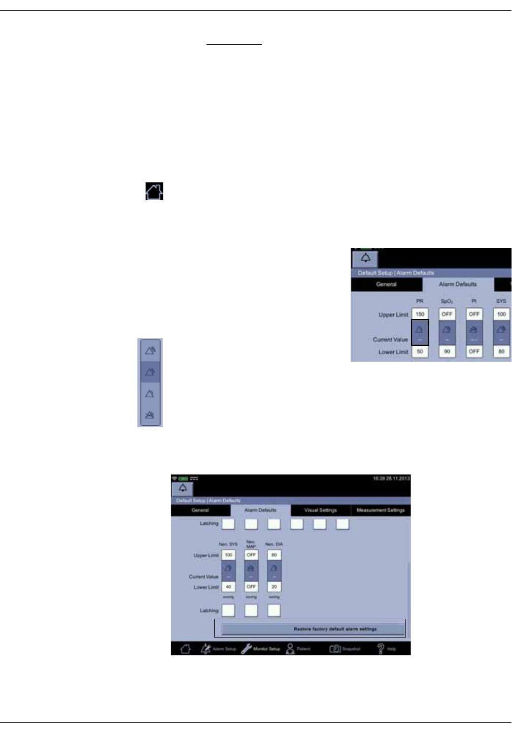
KO00065K VC150 Vital Signs Monitor 14-5
Default setup: Introduction
WARNING
SpO2 and Pulse Rate alarms are latching by default to prevent a
situation where alarms disappear from the display if a patient under
monitoring becomes asystolic. Consider carefully the possible impact if
setting these alarms to non-latching.
5. To disable a limit, keep selecting the backspace icon until the numeric field is
blank.
6. Select Confirm to confirm the change or select Cancel to cancel the change.
7. Adjust the limits for each patient, especially for neonates and children.
8. When you are finished with alarm setup, select the home icon to save the
settings and return to clinical mode.
Changing priority for the limit
1. Select Monitor Setup > Advanced >
Login Default Setup > Alarm
Defaults.
2. Select the middle section of a limit
bar to adjust priority for the alarm
limit. A disabled limit is displayed as
grayish-blue and cannot be
modified in clinical mode. An
enabled limit is displayed in dark
blue and can be modified in clinical
mode.
3. Select the required alarm priority level in the pop-up image. After the
selection, the pop-up disappears.
NOTE
Restore factory default alarm settings will remove all custom alarm
settings and return to the alarm settings set by the manufacturer.
4. Configure Nellcor or Masimo options, if necessary. Refer to “Nellcor SpO2
configuration” on page 9-27 or “Masimo rainbow® SET® SpO2 configuration”
on page 8-25 for more information on these options.
High
Medium
Low
OFF
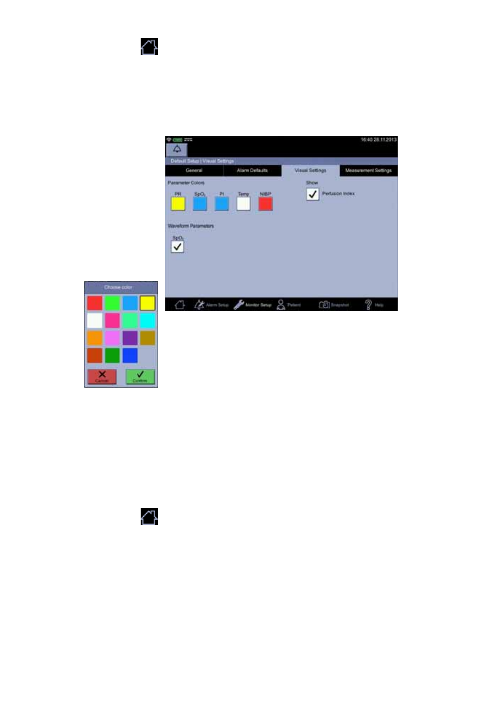
14-6 VC150 Vital Signs Monitor KO00065K
Default setup: Introduction
5. Select the home icon to save the settings and return to clinical mode.
Visual settings
Default colors and parameters displayed on the home screen in clinical mode
can be modified in the Monitor Setup > Advanced > Login Default Setup >
Visual Settings screen.
1. Select an item underneath Parameter colors to change the color of that
parameter on the screen.
2. Select Confirm to confirm the change and save the settings.
3. Select Waveform parameters to display parameter data. You can select
one, a few or all waveform parameters (RR, RRa, SIQ, SpO2).
4. Select items in Show that you want to display on the home screen in clinical
mode.
NOTE
The visual settings you just selected will be applied to the home screen
immediately. If you deselect an item in the Monitor Setup > SpO2 screen, it
will not be displayed on the home screen. If the monitor is restarted, the
monitor will revert to the default settings.
5. Select the home icon to save changes in the default settings and return to
clinical mode.
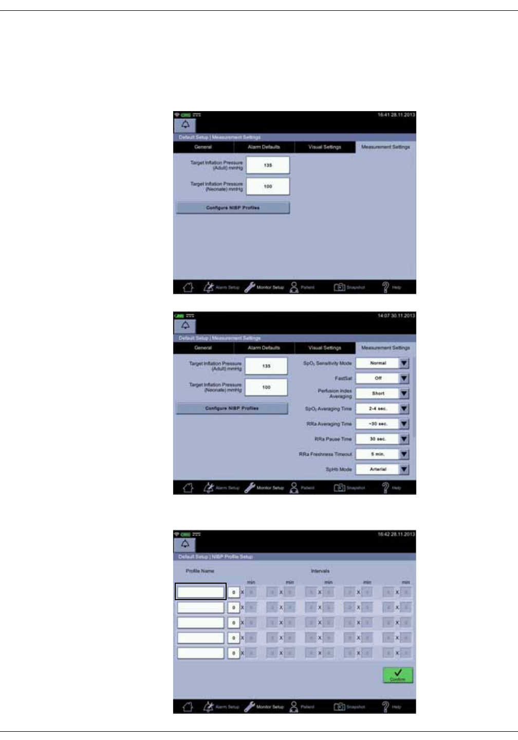
KO00065K VC150 Vital Signs Monitor 14-7
Default setup: Introduction
NIBP profile setup
1. Select Configure NIBP Profiles in the Monitor Setup > Advanced > Login
Default Setup > Measurement settings screen. A pop-up screen will appear
after the selection.
Screen with Masimo
2. Select an NIBP profile name.
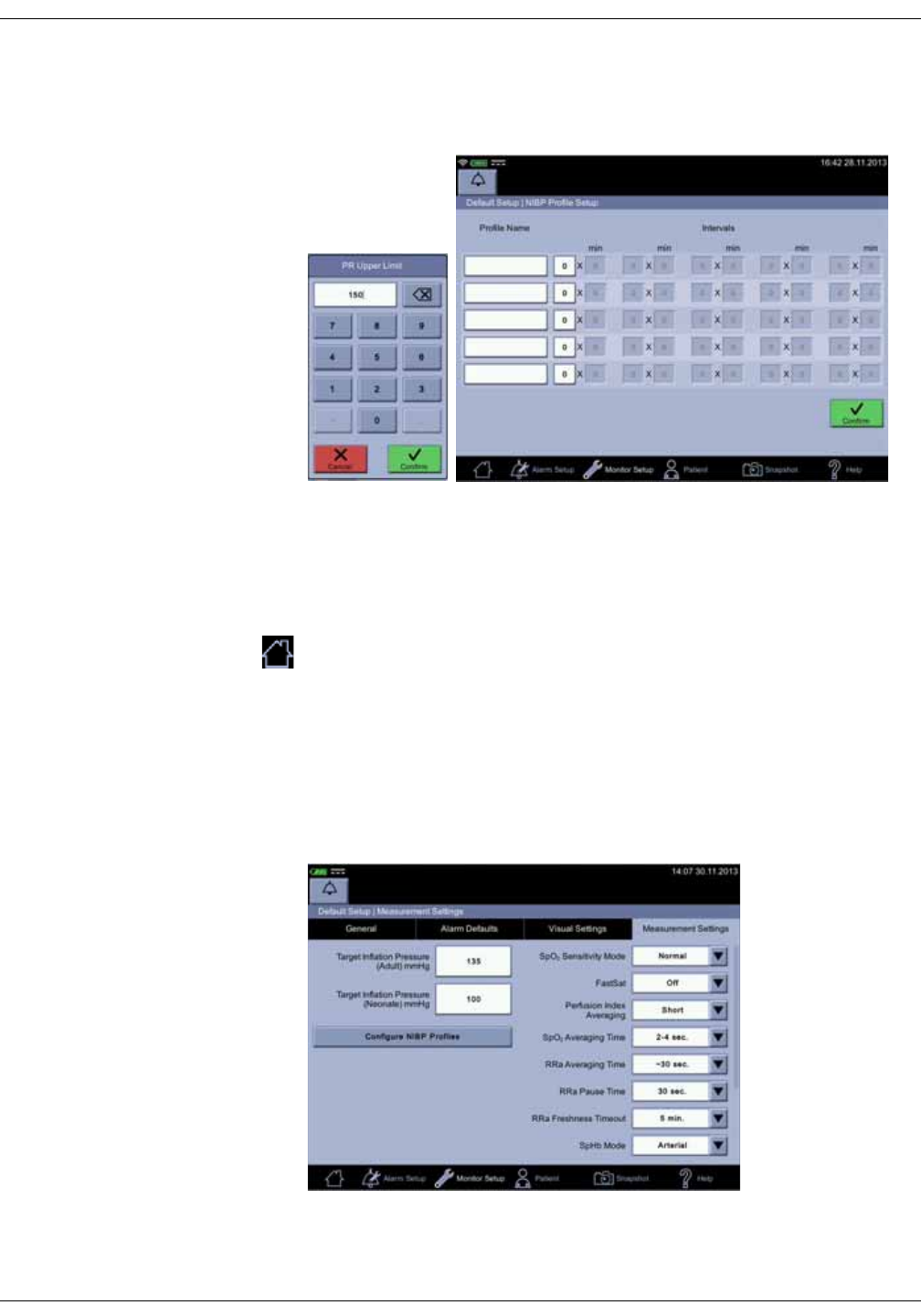
14-8 VC150 Vital Signs Monitor KO00065K
Default setup: Introduction
3. Enter a name for the profile and select Confirm.
4. Enter all interval values one by one, selecting Confirm after each entry. You
can cancel the process with Cancel.
5. Rename and reset other profiles if necessary.
6. If a profile name is incorrect, select that profile name. Then use backspace
to delete the old profile name and enter the correct name.
7. Select Confirm when all settings are complete.
When you are ready with the configuration, select the home icon to save the
settings and exit the configuration mode. When the home icon is selected, the
system will return to clinical mode.
Masimo default settings
Refer to “Masimo rainbow® SET® SpO2 configuration” on page 8-25 for more
information on optional Masimo features available if licenses for these were
purchased with the unit or afterwards.

KO00065K VC150 Vital Signs Monitor A-1
AConnections
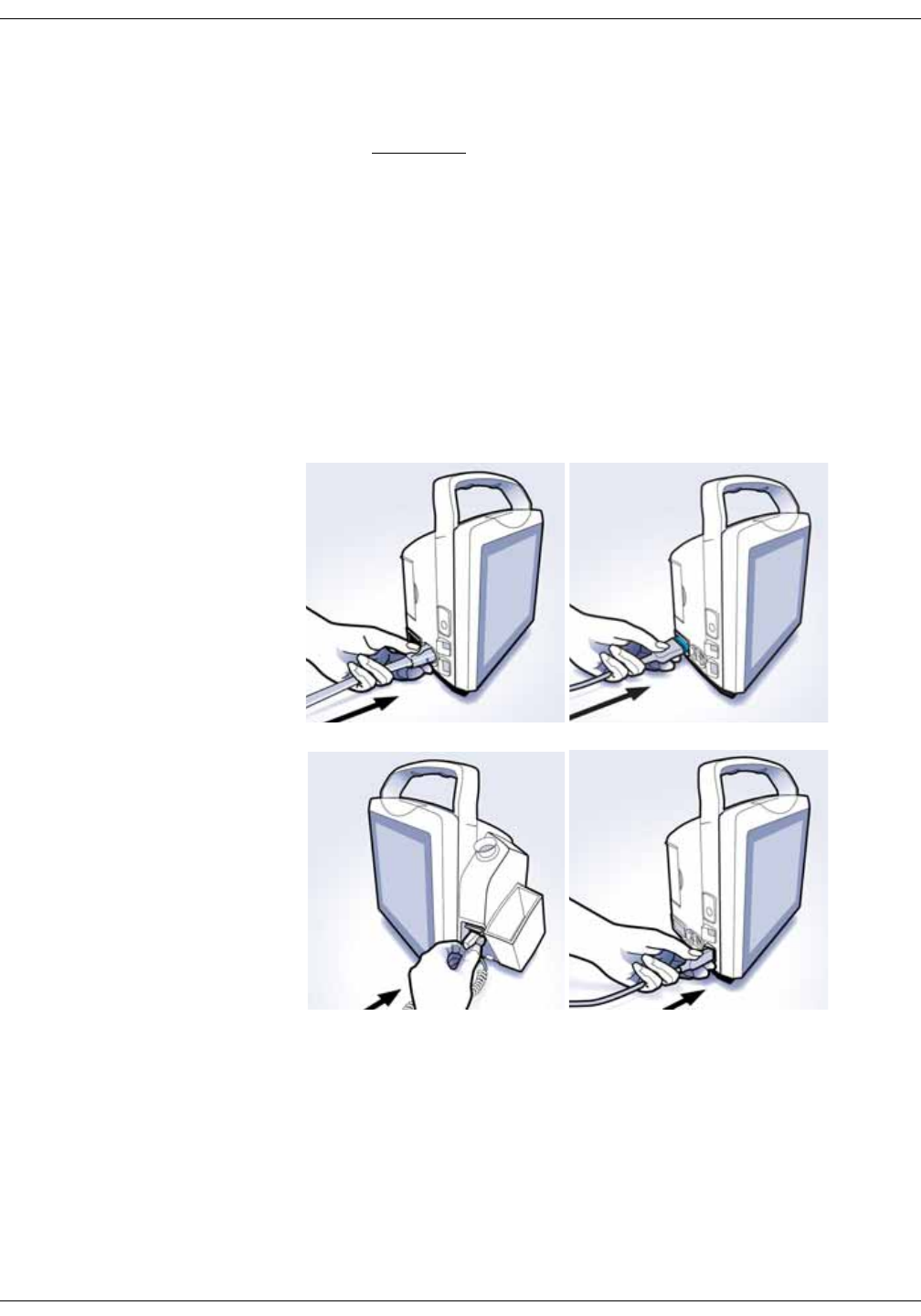
A-2 VC150 Vital Signs Monitor KO00065K
Connections: Connections
Connections
CAUTION
Auxiliary equipment connected to the VC150 vital signs monitor will
result in the formation of an electromedical system, and thus, must
comply with the requirements of IEC 60601-1-1. All host port signals
except for USB-B are non-isolated and should be connected to
equipment conforming to IEC-60601-1 or configured to comply with IEC
60601-1-1 only. Do not connect unapproved devices to the monitor.
Contact your Innokas Medical representative for the VC150 Hostcomm protocol
specification.
• The monitor provides connections for NIBP, SpO2, USB-B, Welch Allyn, three
regular USB-A connections, remote alarm and a power cord. One port is
reserved for a future Medical USB connection. This port is currently not
available.
NIBP
SpO2
Welch
Allyn
Medical
USB
(not currently
available)
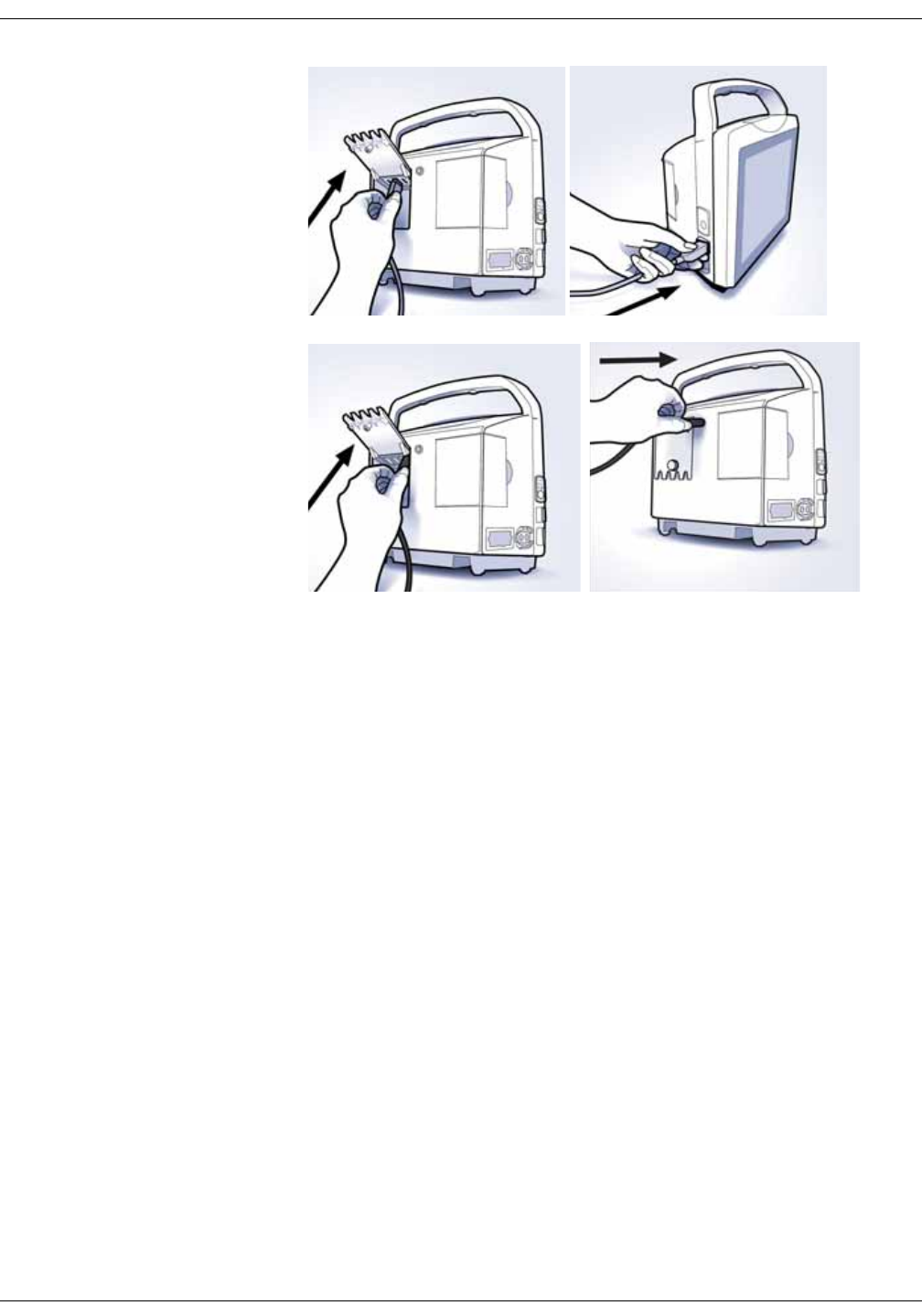
KO00065K VC150 Vital Signs Monitor A-3
Connections: Connections
Refer to “Setting up temperature connection” on page 3-4 for instructions on
how to plug in the Welch Allyn temperature probe.
When a USB-A cable is connected, the monitor tries to find an external USB
device. When a USB-B cable is connected, the monitor can be connected to a PC.
NOTE
If you want to have strain relief on USB-A cable, ask service to perform this.
USB
USB-A
USB-B
Power cord
Remote alarm
connection

A-4 VC150 Vital Signs Monitor KO00065K
Connections: Connections
This page is intentionally left blank.

KO00065K VC150 Vital Signs Monitor B-1
BMaintenance

B-2 VC150 Vital Signs Monitor KO00065K
Maintenance: Service and parts
Service and parts
There are no user-serviceable parts or replaceable fuses inside the monitor.
Refer all service work to service personnel.
If the product fails to function properly, or if assistance, service or spare parts
are required, contact Customer Support. Before contacting Customer Support,
try to duplicate the problem and check all accessories to ensure that they are
not the cause of the problem. If you are unable to resolve the problem after
checking these items, contact Innokas Medical. Prior to calling, please be
prepared to provide:
• product name, model number, and serial number
• a complete description of the problem
If repair parts or service are necessary, you will also be asked to provide:
• the facility's complete name, address
• a purchase order number if the product needs repair or when you order
spare parts
• the appropriate part number for spare or replacement parts
Maintenance
An effective maintenance schedule should be established for your monitoring
equipment and reusable supplies. This should include monthly visual inspection
as well as general monthly cleaning. The maintenance schedule must comply
with the policies of your institution’s infection control unit and/or biomedical
department.
WARNINGS
Failure on the part of the responsible individual, hospital, or institution
using this equipment to implement a satisfactory maintenance
schedule may cause undue equipment failure and possible health
hazards.
Calibration equipment should always be kept dry and free of particulate
matter. Moisture or foreign substances introduced to the pneumatic
system may cause damage to the monitor and/or the accessories,
leading to impaired performance and/or inaccurate readings.
NOTES
• Discard single-use accessories after use.
• There are no user-performed maintenance or calibration procedures for
Welch Allyn thermometry.
• Innokas Medical does not, in any manner, assume the responsibility for
performing the recommended maintenance schedule, unless an Equipment
Maintenance Agreement exists. The sole responsibility rests with the
individuals, hospitals, or institutions utilizing the device.
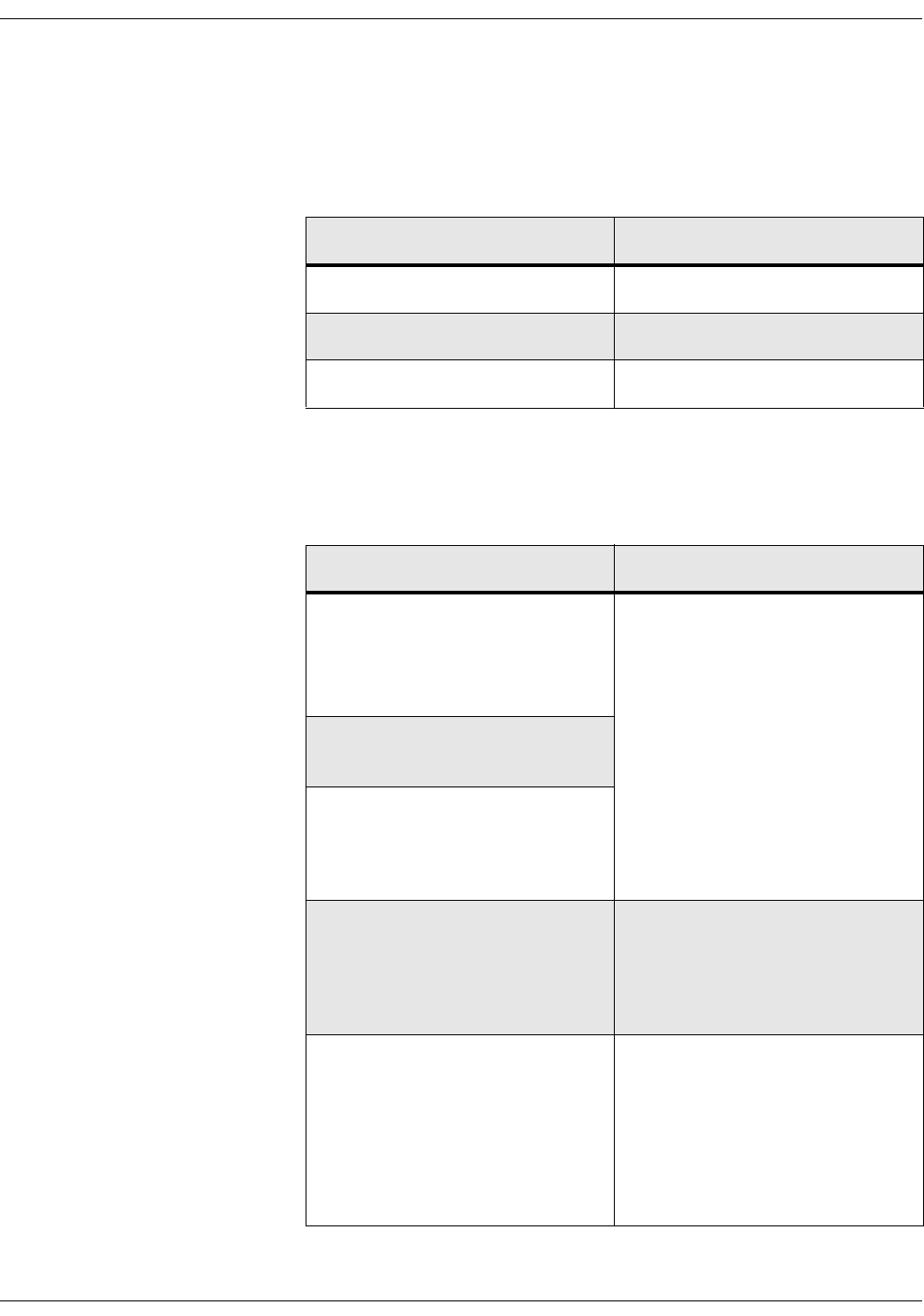
KO00065K VC150 Vital Signs Monitor B-3
Maintenance: Maintenance
User maintenance schedule
Maintenance procedures performed by the daily caregiver help keeping the
monitor uptime as high as possible. The following maintenance schedule is
recommended.
Visual inspection
Check following items and contact service if any of these checks fails.
Maintenance procedure Schedule
Visual Inspection Monthly or as usage requires.
Cleaning Monthly or as usage requires.
Speaker test Monthly or as usage requires.
Inspection item Notes
Any signs of physical damage to:
•the monitor case
• integrity of the display
• the power membrane button
Do not use the monitor if damage is
determined. Have service replace
any damaged parts of the unit.
NOTE
If parts of the display are not
legible or appear corrupt, do not
use the monitor. Have service
replace the display. If the touch
panel appears inaccurate, refer
to “Touch screen recalibration”
on page 3-9.
Loose connectors or frayed cables in
external connections
Safety labels and inscription on the
device clearly legible
Integrity of hoses and cuffs When the pneumatic integrity of any
NIBP cuff and hose is in doubt,
replace the cuff and hose and
discard the questionable
accessories.
Speaker test 1. Switch the monitor on and wait
to hear two beeps.
2. Unplug and plug the power
supply cord. A chirping sound is
heard.
If you do not hear either of these,
contact service.

B-4 VC150 Vital Signs Monitor KO00065K
Maintenance: Calibration
WARNING
Do not use damaged sensors, cables, or connectors.
Calibration
User can only recalibrate the touch screen. Refer to “Touch screen recalibration”
on page 3-9, if necessary. No other user-lever calibrations are required.
Cleaning
List of approved cleaning agents
Use only these cleaning agents to clean the monitor unit or the Welch Allyn
probe well. Periodically, Innokas Medical evaluates additional cleaning agents
for compatibility with the monitor. If your cleaning agent is not listed in this
section, contact your Innokas Medical representative to determine if additional
information is available.
NOTES
The touch screen surface is made of PET (polyethylene terephthalate) and
must not be cleaned with any solvent or any alkaline cleaning agent.
If you want to use other cleaning agents than those specifically approved
and listed in this section, you can do it at your own risk. However, bear in
mind that using non-approved cleaning agents voids the product warranty
on all monitor parts that may come in touch with non-approved cleaning
agents. If you still want to use a non-approved cleaning agent, first test it on
the corner of the touch screen, not on the whole screen. Remember to wipe
off possible residues or stains with a cloth dampened with water.
List of approved cleaning agents for VC150 monitor and accessories
(except Welch Allyn SureTemp® Plus)
Cavicide® Surface
Cleaner/Disinfectant
Sagrotan®
Alternative
Sani-Cloth® HB Sporicidin®
Virex 256 Water (distilled) Windex Blue
List of approved cleaning agents for Welch Allyn SureTemp® Plus
Probe well Warm water and a mild detergent solution.
Thermometry probe 70% Isopropyl alcohol 10% bleach solution and
Cavicide® or equivalent.

KO00065K VC150 Vital Signs Monitor B-5
Maintenance: Cleaning
Prohibited cleaning agents
Never use the following cleaning agents on the monitor, monitor accessories, or
the Exergen temporal scanner:
• Abrasive cleaners or solvents of any kind
•Acetone
•Ketone
• Betadine
• Alcohol-based cleaning agents. (However, an alcohol-based cleaning agent
can be used on the Welch Allyn temperature metal probe and plastic section
of the probe, Exergen scanner’s lens, probe head and metal neck only.)
• Petroleum-based cleaning agents
• Any type of solution that contains ammonium chloride, conductive
solutions, wax or wax compounds
• Sodium salts
NOTE
Never autoclave or steam clean the monitor, cuffs, or accessories.
Cleaning schedule
To prevent cross-contamination, clean exterior surfaces of the monitor, monitor
accessories, and reusable sensors on a regular basis in compliance with your
institution's infection control unit and/or biomedical department's local policy.
Procedure
WARNINGS
Always shut down the monitor and disconnect it from the electrical
network before any cleaning procedure.
Prior to using a cleaning agent, read the instructions for use and adhere
to provided safety precautions.
Never pour or spray water or any cleaning solution on the equipment or
permit fluids to run behind switches, into connectors, into the printer, or
into any ventilation openings in the equipment. Do not let fluid “pool”
around connection pins. Do not immerse the monitor, the sensors or the
hoses in liquids.
Use of unapproved cleaning agents can cause case damage resulting
in unintended fluid ingress and a potential for compromising electrical
safety.
Do not use steam, heat, chemical or gas sterilization on the monitor or
its accessories. Do not autoclave the accessories.
NOTE
Clean the monitor and sensors according to local policies.

B-6 VC150 Vital Signs Monitor KO00065K
Maintenance: Cleaning
Cleaning the exterior surfaces
Disconnect the monitor from AC power before cleaning or disinfecting its
surface. The exterior surfaces of the monitor, monitor accessories, and temporal
scanner may be cleaned with a lint-free cloth, dampened with a cleaning agent
listed in “List of approved cleaning agents” on page B-4. Wipe off all cleaning
solutions with a clean, dry cloth and let air dry for at least 15 minutes.
NOTE
Exergen temporal scanner only: Alcohol-based cleaning agents can be used
on the scanner’s lens, probe head and metal neck only.
Cleaning the screen
To clean the VC150 monitor screen or the Exergen screen, use a soft, clean cloth
dampened with a cleaning agent listed in “List of approved cleaning agents” on
page B-4. Never spray the cleaning agent directly onto the display.
Cleaning the Exergen sensor lens
Dirt, greasy film, or moisture on the scanner
lens will interfere with the accuracy of the
temperature reading. Regularly clean the lens
with a cotton swab dipped in alcohol and
follow the instruction label on the scanner.
Only use gentle pressure for cleaning to avoid
lens damage. Do not use bleach or other cleaning solutions on the sensor lens.
Cleaning the Exergen probe head and neck
Use an alcohol-based cleaning agent on the Exergen scanner’s probe head and
metal neck only.
Cleaning and disinfecting blood pressure cuffs and air hoses
General
Before reuse, the cuff and the air hose must be thoroughly cleaned with a
cleaning agent listed in “List of approved cleaning agents” on page B-4.
WARNINGS
Consult the manufacturer for specific cleaning or disinfection
instructions of the cuffs and air hoses. The user has the responsibility to
validate any deviations from the recommended method of cleaning and
disinfection.
Never autoclave or steam clean the monitor, cuffs, or accessories.

KO00065K VC150 Vital Signs Monitor B-7
Maintenance: Cleaning
Cleaning the Welch Allyn probe and probe well
Units that are in service on a regular basis should have the following preventive
maintenance performed every six months:
1. Visually inspect the thermometer probe for any physical damage that might
cause future product failure.
2. Clean the probe and the probe well according to instructions below. Use an
alcohol-based cleaning agent on the Welch Allyn metal probe or plastic
section of the probe only.
Cleaning the Welch Allyn probe
As needed, clean the probe with a 70% isopropyl alcohol solution or a 10%
chlorine bleach solution or a nonstaining disinfectant such as CaviCide® or its
equivalent.
WARNING
Do not immerse or soak the probe in any type of fluid. Do not use steam,
heat or gas sterilization on the probe. Do not autoclave the probe.
CAUTION
Never immerse any monitor accessories.
Cleaning the removable probe well
1. Remove the probe well from the unit.
2. Unplug the latching probe connector to prevent the monitor
from consuming battery power while you are cleaning the
probe well.
3. Clean the inner surface of the probe well by swabbing the
surface with a cloth dampened with a mild detergent
solution or a 70% isopropyl alcohol, or a 10% chlorine bleach solution, or a
nonstaining disinfectant such as CaviCide® or its equivalent.
4. Clean the probe well’s outer surface by swabbing or wiping the surface with
one of the solutions mentioned above. Immerse the probe well in mild
detergent solution as necessary for cleaning.
5. Thoroughly dry all surfaces before re-assembling the instrument.
6. Reconnect the latching probe connector to the monitor. Ensure that the
connector snaps into place.
7. Reinstall the probe well in the monitor and snap the probe well into place.
8. Insert the probe into the probe well.

B-8 VC150 Vital Signs Monitor KO00065K
Maintenance: Battery and monitor storage care
WARNING
Do not use hard or sharp objects to clean the probe well. This could
damage it and cause the unit to not function properly. Do not use
steam, heat or gas sterilization on the thermometer or probe. Do not
autoclave the probe well.
9. Periodically clean the probe’s surface by wiping it with a soft cloth, sponge
or soft brush dampened with a cleaning agent listed above for Welch Allyn.
Then wipe dry with a clean cloth or towel.
Cleaning SpO2 sensors
Adhesive sensors are sterile and for single use only. For reusable SpO2 sensors,
consult the sensor manufacturer instructions for cleaning, sterilization, or
disinfecting methods.
Battery and monitor storage care
Short-term storage
The monitor and its accessories should be stored in a clean and stable place
with no weight applied on them.
Keep the monitor connected to an external DC power source when not in use to
ensure maximum battery charge. As long as the monitor remains connected to
an external DC power source, the monitor will charge the battery whenever
software determines it necessary.
Batteries should always be connected and fully charged before being placed in
short-term storage. It is recommended that batteries should not be left in
storage more than 2 weeks without a full recharge. When the battery will no
longer hold a charge, contact service for battery replacement.
NOTE
After replacing batteries/battery discharge/patient discharge, the monitor
will clear user settings and revert to default settings set in the configuration
mode.
Extended storage
When storing the monitor for extended periods, contact service for battery
disconnection and packing of the monitor and the accessories.
Storage temperature
When packaged according to instructions in the Service Manual, the device
survives a storage temperature range of – 20° C to + 50° C (– 4° F to + 122° F).

KO00065K VC150 Vital Signs Monitor B-9
Maintenance: Repairs
Repairs
If your product requires warranty, extended warranty, or non-warranty repair
service, contact Innokas Medical Technical Support or your local Innokas
Medical representative.
Estimates for non-warranty repairs are provided at no charge; however, the
product must be sent to Innokas Medical for an estimate. To facilitate prompt
service in cases where the product has external chassis or case damage, please
advise the representative when you call.
The representative will record all necessary information and will provide a
Return Authorization Number. Prior to returning any product for repair, a Return
Authorization Number must be obtained.
Changing the Exergen temperature unit battery
Required tools and parts
• Paper clip or metal pin of equal thickness
• A new quality alkaline 9V battery
NOTE
If the Exergen scanner is not used regularly, remove the battery to prevent
possible damage due to chemical leakage.
Procedure
1. Unplug the scanner cable from the monitor USB port.
2. Bend a paper clip or obtain a metal pin of equal thickness and then insert it
into a small hole on the side of the Exergen frame (A).
3. Push the pin inside until the battery cover (B) is released.
4. Remove the cover.
5. Remove and disconnect the battery (C).
6. Replace the battery.
7. Place the lower end of the cover (D) in the groove.
8. Then push the upper part (E) down until it locks up.
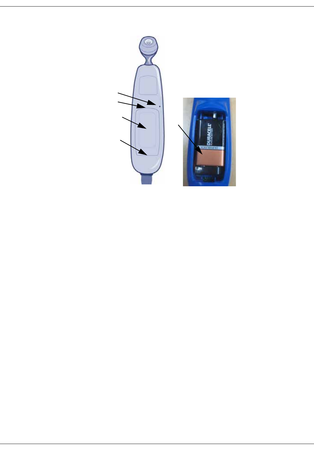
B-10 VC150 Vital Signs Monitor KO00065K
Maintenance: Packaging material
9. Plug the scanner cable into the USB port.
Verification
Check the LED display. The low battery error message should not be displayed.
Perform a temperature measurement to determine whether the Exergen unit is
powered correctly. Refer to “Disposal of product waste” on page B-11 for battery
disposal instructions.
Packaging material
Retain original packaging materials for future use in storing or shipping the
monitor and accessories. This recommendation includes corrugated shippers
and foam/corrugated spacers.
If you decide to dispose of these materials, we recommend recycling them.
Packing instructions
If you have to return goods for service, follow these instructions:
• Remove all hoses, cables, sensors, and power cords from the monitor before
packing.
• Clean the unit as instructed in “Cleaning” on page B-4.
• Ask service to pack the unit for shipping.
A
E
B
D
C

KO00065K VC150 Vital Signs Monitor B-11
Maintenance: Disposal of product waste
Disposal of product waste
As you use the monitor, you will accumulate solid wastes that require proper
disposal or recycling. These include batteries, patient applied parts, and
packaging material. Dispose of these materials according to local or national
regulations.
Batteries
The Li-Ion rechargeable battery can be recycled. Do not puncture or place the
battery in a trash compactor. Do not incinerate the battery or expose it to fire or
high temperatures. Dispose of these materials according to local or national
regulations.
Dispose any battery in accordance with local regulations on material recycle.
Patient-applied parts
Certain patient-applied parts, such as those with adhesive (disposable SpO2
sensors), are intended for single use and should be disposed of properly as
medical waste in accordance with regional body controlled guidelines.
Other patient-applied parts, such as blood pressure cuffs, should be cleaned
according to instructions. Inspect reusable applied parts for wear before each
use, replace as necessary, and dispose of used product as medical waste in
accordance with regional body controlled guidelines.
Monitor
At the end of its service life, the product described in this manual, as well as its
accessories, must be disposed of in compliance with the guidelines regulating
the disposal of such products. If you have questions concerning disposal of the
product, please contact Innokas Medical or its representatives.

B-12 VC150 Vital Signs Monitor KO00065K
Maintenance: Disposal of product waste
This page is intentionally left blank.

KO00065K VC150 Vital Signs Monitor C-1
CPrinciples of
noninvasive blood
pressure
determination (NIBP)

C-2 VC150 Vital Signs Monitor KO00065K
Principles of noninvasive blood pressure determination (NIBP): DINAMAP SuperSTAT algorithm
DINAMAP SuperSTAT algorithm
The oscillometric method of determining NIBP is accomplished by a sensitive
transducer which measures cuff pressure and pressure oscillations within the
cuff. For the first determination taken on a patient, the algorithm stores the
pattern of the patient's oscillation size as a function of the pressure steps.
When NIBP measurements are performed: 1) the monitor will use a previous
NIBP value for adaptive target inflation pressure as long as this is displayed on
the screen. 2) the NIBP values are displayed for a maximum of 30 minutes or
until another determination is initiated. When the values on the screen expire or
the patient is discharged, the adaptive target pressure will be automatically
cleared.
For subsequent single, auto, or STAT determinations taken before data of the
previous determination of the same patient has expired, as few as four pressure
steps may be necessary to complete the determination process. When
employing fewer pressure steps, the system uses the stored information from
the previous blood pressure determination to decide the best pressure steps to
take. The algorithm measures the consistency of pulse size to tell if the
oscillations taken at a step are good and if more steps are needed.
The first determination settles at an initial target pressure of 135 mmHg (adult
mode) and 100 mmHg (neonate mode), depending on initial target pressure
preset. To allow for rapid settling of cuff pressure, the monitor will momentarily
inflate to a higher pressure then immediately deflate to the target pressure. After
inflating the cuff, the NIBP parameter begins to deflate. The oscillations versus
cuff pressure are measured to determine the mean pressure and calculate the
systolic and diastolic pressures.
During an NIBP determination, the parameter deflates the cuff one step each
time it detects two pulsations of relatively equal amplitude. The time between
deflation steps depends on the frequency of these matched pulses (pulse rate of
the patient). However, if the monitor is unable to find any pulse within several
seconds, it will deflate to the next step. The process of finding two matched
pulses at each step provides artifact rejection due to patient movement and
greatly enhances the accuracy of the monitor. The figure shows a full
determination sequence for an adult patient.
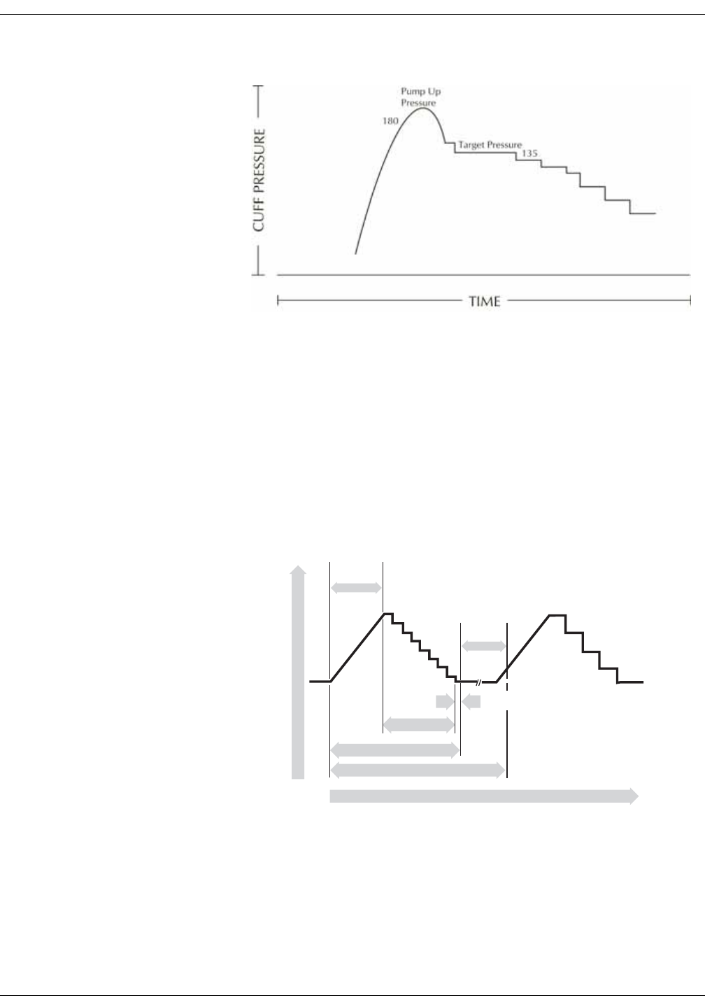
KO00065K VC150 Vital Signs Monitor C-3
Principles of noninvasive blood pressure determination (NIBP): DINAMAP SuperSTAT algorithm
Full NIBP determination sequence for adult
(specific pressure values are examples only)
At each step the microprocessor stores cuff pressure, the matched pulse
amplitude, and the time between successive pulses. The stepped deflation and
matched pulse detection continues until diastolic pressure is determined or total
cuff pressure falls below 8 mmHg. The parameter then deflates the cuff (to zero
detected pressure), analyzes the stored data, and updates the screen.
The operating cycle is composed of four parts: inflation time, deflation time,
evaluation time, and wait time. Wait time, which varies from mode to mode, is
affected by the cycle time (auto mode) or operator intervention (manual mode).
The figure shows the basic operating cycle for an NIBP determination.
SuperSTAT NIBP - auto mode
CUFF PRESSURE
TIME
Inflation
Time
Cycle Time
Determination Time
Deflation Time
Evaluation Time
Wait Time

C-4 VC150 Vital Signs Monitor KO00065K
Principles of noninvasive blood pressure determination (NIBP): DINAMAP auscultatory reference algorithm
Systolic search
NOTE
Arrhythmias will increase the time required by the NIBP parameter to
determine a blood pressure.
If systolic pressure is not found, the SuperSTAT algorithm can search at cuff
pressures higher than the initial target pressure. The algorithm will inflate above
the initial target pressure to obtain more data in the systolic region. The pressure
is limited to the maximum allowed for the selected patient type.
The SuperSTAT algorithm evaluates the data obtained during the determination,
and the prior determination if it is available, to determine if additional data is
needed to complete the determination. It can then selectively pump to a single
cuff pressure to obtain the data it needs and then return to the existing deflation
sequence. This search process makes SuperSTAT more efficient.
Accuracy of the SuperSTAT NIBP measurements was validated against the intra-
arterial method. Do not use the auscultatory method to verify the accuracy of
the SuperSTAT NIBP parameter. The auscultatory method (using the cuff and
stethoscope) determines the systolic and diastolic pressures from sounds that
occur during cuff deflation. Mean arterial pressure cannot be determined by the
auscultation method. The oscillometric method used with all DINAMAP
technologies determines systolic, mean and diastolic pressures from the
oscillation pattern that occurs in the cuff during deflation.
DINAMAP auscultatory reference algorithm
The oscillometric method of determining NIBP is accomplished by a sensitive
transducer, which measures cuff pressure and minute pressure oscillations
within the cuff. The first determination sequence initially pumps up to a cuff
pressure of about 160 mmHg for adult/pediatric patients depending on preset
initial target pressure. After inflating the cuff, the monitor begins to deflate it and
measures systolic pressure, mean arterial pressure, and diastolic pressure.
When the diastolic pressure has been determined, the monitor finishes deflating
the cuff and updates the screen.
The auscultatory reference is an algorithm based upon Korotkoff sounds and a
stethoscope. It is used only for adults/peds because neonates and babies/
toddlers under 3 years do not produce adequate Korotkoff sounds. The monitor
deflates the cuff one step each time it detects two pulsations of relatively equal
amplitude. The time between deflation steps depends on the frequency of these
matched pulses (pulse rate of the patient). However, if the monitor is unable to
find any pulse within several seconds, it will deflate to the next step. The process
of finding two matched pulses at each step provides artifact rejection due to
patient movement and greatly enhances the accuracy of the monitor. The figure
shows the NIBP determination sequence.
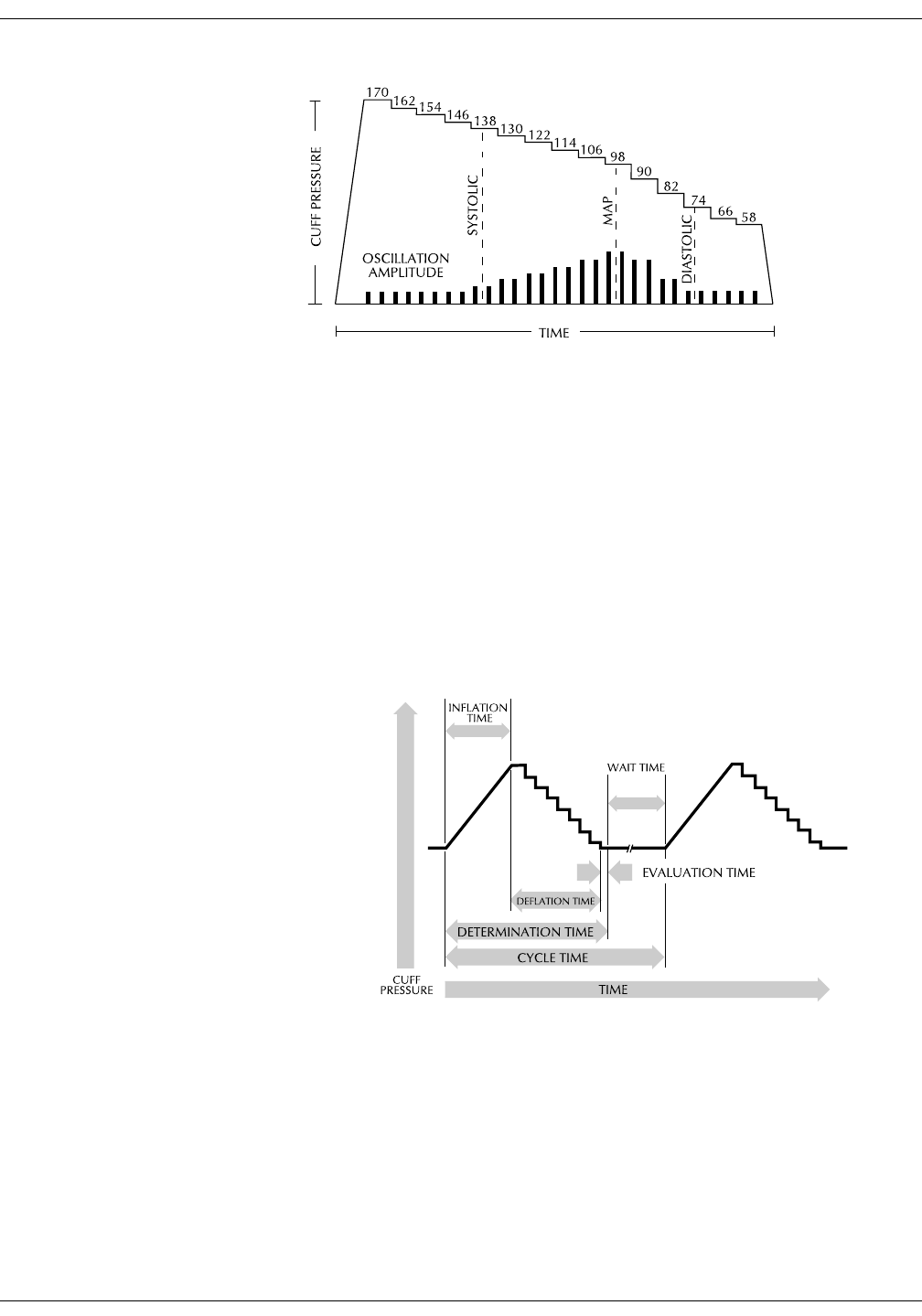
KO00065K VC150 Vital Signs Monitor C-5
Principles of noninvasive blood pressure determination (NIBP): DINAMAP auscultatory reference algorithm
NIBP determination sequence
(specific pressure values are examples only)
At each step the microprocessor stores cuff pressure, the matched pulse
amplitude, and the time between successive pulses. The stepped deflation and
matched pulse detection continues until diastolic pressure is determined or total
cuff pressure falls below 7 mmHg. The monitor then deflates the cuff (to zero
detected pressure), analyzes the stored data, and updates the screen.
The operating cycle is composed of four parts: inflation time, deflation time,
evaluation time, and wait time. Wait time, which varies from mode to mode, is
affected by the cycle time (auto mode) or operator intervention (manual mode).
The figure shows the basic operating cycle.
NIBP operating cycle

C-6 VC150 Vital Signs Monitor KO00065K
Principles of noninvasive blood pressure determination (NIBP): DINAMAP auscultatory reference algorithm
Systolic search
If systolic pressure is not found, the NIBP parameter can search at cuff pressures
higher than the initial target pressure. The parameter will inflate the cuff above
the initial target pressure to get more data in the systolic region. The pressure is
limited to the maximum allowed for the selected patient type.
In any operating mode, if a patient's systolic pressure exceeds the inflation
pressure of the monitor, the monitor will begin normal deflation sequence,
detect the absence of a systolic value, stop deflation, reinflate to a higher (than
initial) inflation pressure, and resume normal deflation sequence.
In manual mode, if a previous valid systolic pressure is displayed and less than 2
minutes old, and the new systolic pressure oscillations are compared with the
previous valid determination and the monitor "thinks" that the systolic was not
obtained, the monitor will inflate the cuff to a pressure above the immediately
preceding inflation.
Reference used to determine NIBP accuracy
To establish accuracy of an NIBP device, manufacturers have used several
different types of references. The reference blood pressures may be obtained by
invasive pressure monitoring at the central aortic region or at the radial sites.
The reference blood pressures may also be obtained by noninvasive methods
like auscultatory method (using cuff and stethoscope).
NOTE
For neonatal mode, the reference is always the intra-arterial pressure
monitoring method.
Monitors with intra-arterial reference (DINAMAP SuperSTAT technology)
In these monitors, the NIBP is referenced to the invasive blood pressure obtained
at the central aortic region.
Monitors with auscultatory reference (DINAMAP auscultatory reference technology)
In these monitors, the reference blood pressure is the auscultatory method for
adult and pediatric populations. For neonatal populations, the usual reference is
the invasive blood pressure obtained from the umbilical artery.
NOTE
For neonatal determinations the SuperSTAT algorithm is always used.

KO00065K VC150 Vital Signs Monitor D-1
DSupplemental
analysis of clinical
accuracy test data
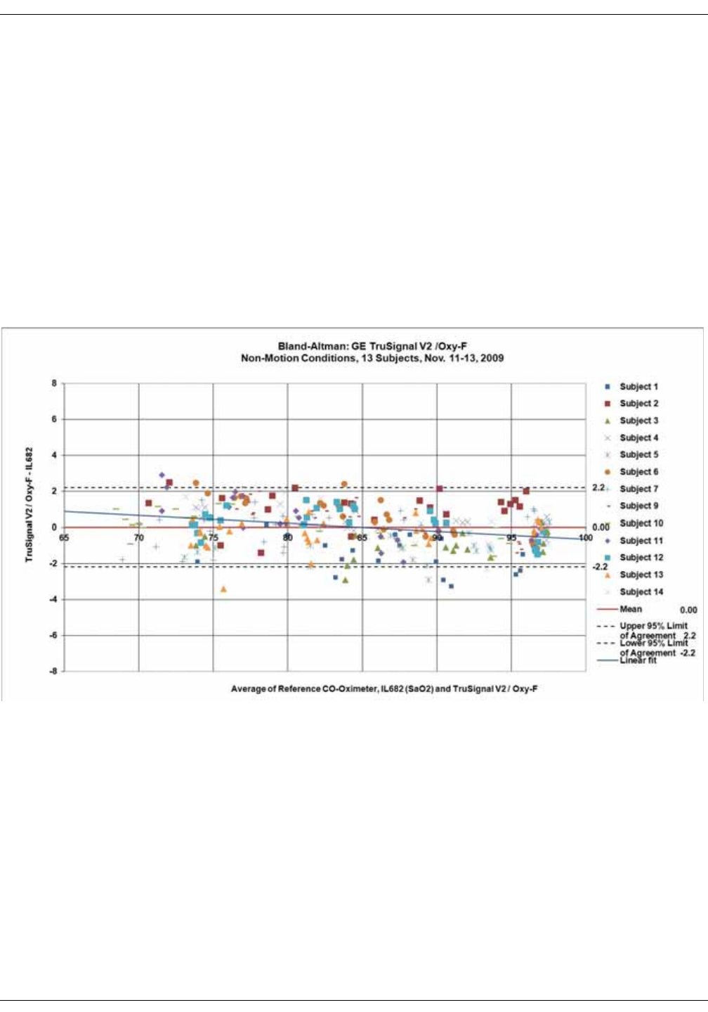
D-2 VC150 Vital Signs Monitor KO00065K
Supplemental analysis of clinical accuracy test data: GE TruSignal V2
GE TruSignal V2
Supplemental Analysis of Clinical Accuracy Test Data for GE TruSignal V2
SpO2 Measurement
The supplemental data analysis is performed to present the data per a format of
Bland-Altman1.
The supplemental analysis includes the Bland-Altman graph with a linear
regression fit and the upper 95% and lower 95% limits of agreement (Mean ±
1.96 * standard deviation). Additionally the sampled data points are
differentiated for each individual test subject by color and style. Figures 1 to 8
represent different sensors under test.
Figure 1. Bland-Altman plot of GE TruSignal V2 with Oxy-F sensor. Population
mean bias: 0.0, upper 95% limit of agreement: 2.2, lower 95% limit of agreement:
-2.2, between subject variance: 10.2, within-subject variance: 0.9.
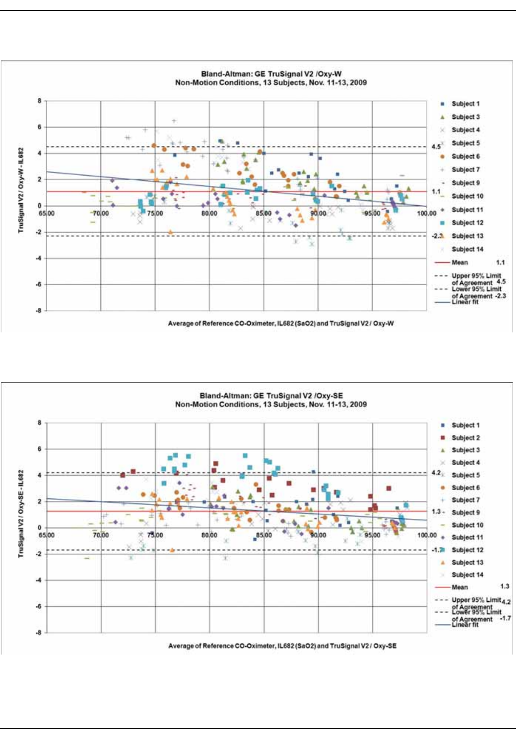
KO00065K VC150 Vital Signs Monitor D-3
Supplemental analysis of clinical accuracy test data: GE TruSignal V2
Figure 2 Bland-Altman plot of GE TruSignal V2 with Oxy-W sensor. Population
mean bias: 1.1, upper 95% limit of agreement: 4.5, lower 95% limit of agreement:
-2.3, between subject variance: 41.5, within-subject variance: 1.5.
Figure 3 Bland-Altman plot of GE TruSignal V2 with Oxy-SE sensor. Population
mean bias: 1.3, upper 95% limit of agreement: 4.2, lower 95% limit of agreement:
-1.7, between subject variance: 29.2, within-subject variance: 1.2.
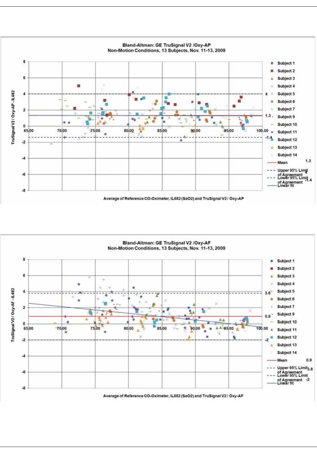
D-4 VC150 Vital Signs Monitor KO00065K
Supplemental analysis of clinical accuracy test data: GE TruSignal V2
Figure 4 Bland-Altman plot of GE TruSignal V2 with Oxy-AP sensor. Population
mean bias: 1.3. Upper 95% limit of agreement: 4.0, lower 95% limit of agreement:
-1.4. Between subject variance: 11.4, within-subject variance: 1.3.
Figure 5 Bland-Altman plot of GE TruSignal V2 with Oxy-AF sensor. Population
mean bias: 0.9, upper 95% limit of agreement: 3.8, lower 95% limit of agreement:
-2.0, between subject variance: 10.7, within-subject variance: 1.7.
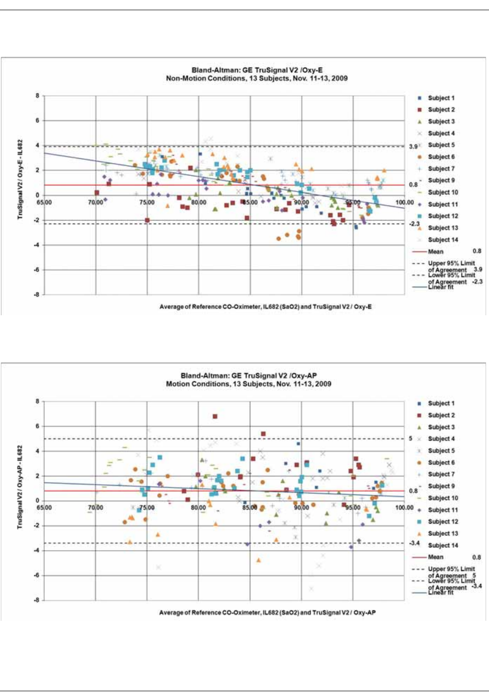
KO00065K VC150 Vital Signs Monitor D-5
Supplemental analysis of clinical accuracy test data: GE TruSignal V2
Figure 6 Bland-Altman plot of GE TruSignal V2 with Oxy-E sensor. Population
mean bias: 0.8, upper 95% limit of agreement: 3.9, lower 95% limit of agreement:
-2.3, between subject variance: 20.8, within-subject variance: 1.7.
Figure 7 Bland-Altman plot of GE TruSignal V2 with Oxy-AP sensor, motion
conditions. Population mean bias: 0.8. Upper 95% limit of agreement: 5.0, lower
95% limit of agreement:-3.4. Between subject variance: 22.6, within-subject
variance: 3.6.
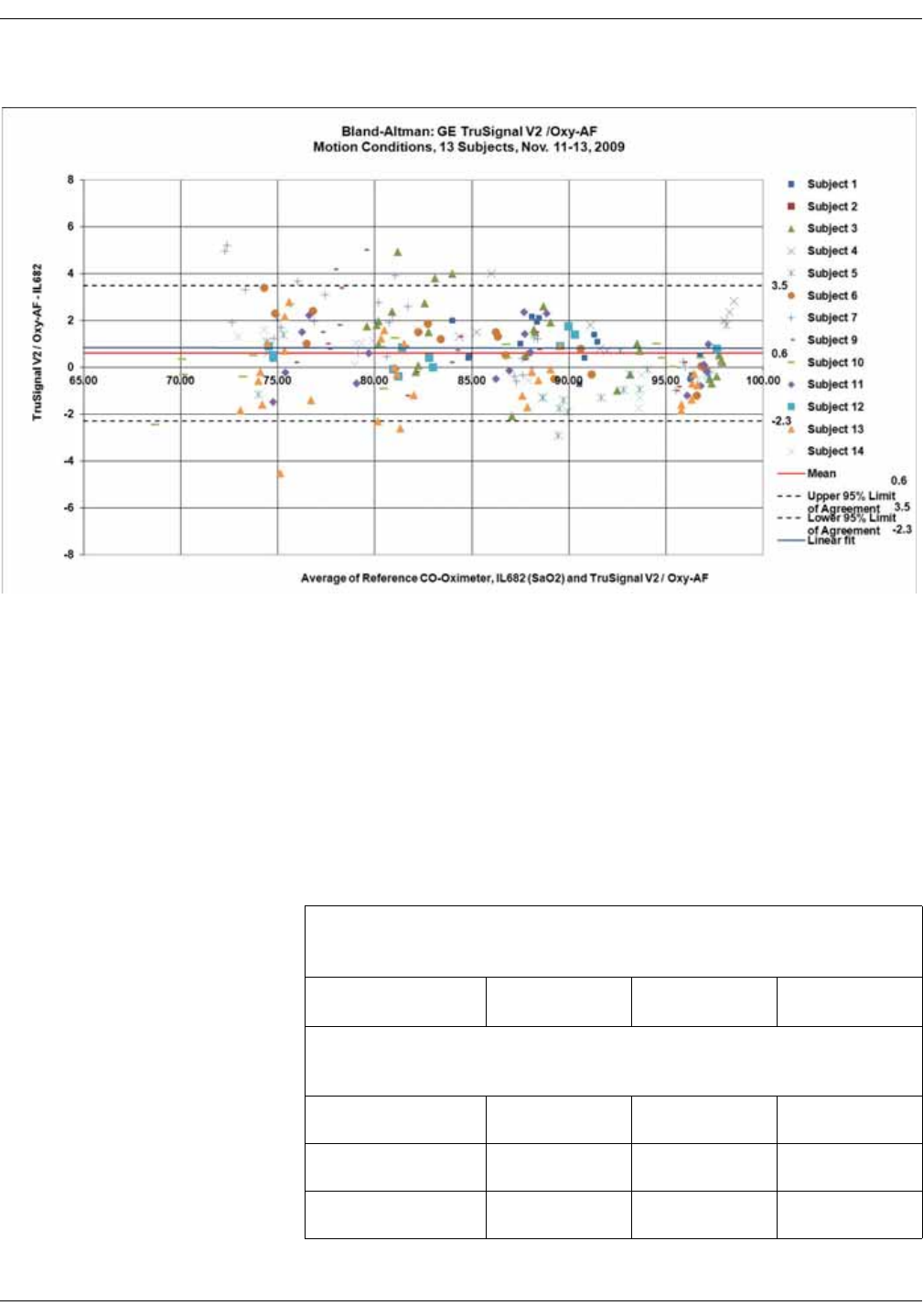
D-6 VC150 Vital Signs Monitor KO00065K
Supplemental analysis of clinical accuracy test data: GE TruSignal V2
Figure 8 Bland-Altman plot of GE TruSignal V2 with Oxy-AF sensor, motion
conditions. Population mean bias: 0.6. Upper 95% limit of agreement: 3.5, lower
95% limit of agreement:-2.3. Between subject variance: 10.5, within-subject
variance: 1.7.
Reference:
1 “Agreement Between Methods Of Measurement With Multiple Observations Per
Individual“, by Bland and Altman in 2007 Journal of Biopharmaceutical Statistics.
Section 3: Method Where the True Value Varies.
Clinical test results
Arms values measured using GE SpO2 sensors with GE CARESCAPETM V100
in a clinical study.*
GE SpO2 Sensor 70 - 80% 80 - 90% 90 - 100%
*The sensors were clinically tested for accuracy with the following
sensors:
OXY-E 2.3 digits 1.4 digits 1.3 digits
OXY-SE 2.5 digits 2.0 digits 1.1 digits
OXY-F 1.3 digits 1.0 digits 1.1 digits

KO00065K VC150 Vital Signs Monitor D-7
Supplemental analysis of clinical accuracy test data: GE TruSignal V2
OXY-W 2.9 digits 1.8 digits 1.0 digits
OXY-AP 2.0 digits 1.9 digits 1.7 digits
OXY-AF 2.5 digits 1.4 digits 0.9 digits
*The sensors were clinically tested for accuracy with the following
sensors:
OXY-E (equivalent to OXY-E-UN, TS-E-D, TS-E2-GE, TS-E4-GE)
OXY-SE (equivalent to OXY-SE-3, TS-SE-3)
OXY-F (equivalent to OXY-F-UN, TS-F-D, TS-F2-GE, TS-F4-GE, TS-SA-D, TS-SA4-
GE)
OXY-W (equivalent to OXY-W-UN, TS-W-D)
OXY-AP (equivalent to OXY-AP-10, OXY-AP-25, TS-AP-10, TS-AP-25)
OXY-AF (equivalent to OXY-AF-10, TS-AF-10, TS-AF-25)
*The sensors were clinically tested for neonatal accuracy with the
following sensors:
OXY-SE (equivalent to OXY-SE-3, TS-SE-3)
OXY-AF (equivalent to OXY-AF-10, TS-AF-10, TS-AF-25)
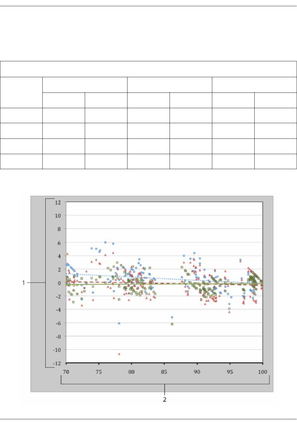
D-8 VC150 Vital Signs Monitor KO00065K
Supplemental analysis of clinical accuracy test data: Nellcor accuracy study results
Nellcor accuracy study results
Accuracy was calculated using the root mean square difference (RMSD).
SpO2 Accuracy for Nellcor™ Sensors vs. CO-oximeters
SpO2 decade MAX-A MAX-N MAX-FAST
Data Points Arms Data Points Arms Data Points Arms
60-70713.05712.89712.22
70-80552.35552.32551.28
80-90481.84481.73481.48
90-100 117 1.23 117 1.68 117 0.98

KO00065K VC150 Vital Signs Monitor D-9
Supplemental analysis of clinical accuracy test data: Masimo sensor accuracy
Modified Bland-Altman plot
Masimo sensor accuracy
Performance Specifications for Masimo M-LNCS, LNCS, and LNOP
Adhesive Sensors
Table information provides Arms values measured using the M-LNCS Series,
LNCS Series and LNOP Series sensors with Masimo SET Oximetry Technology in a
clinical study. SaO2 versus error (SpO2 – SaO2) with linear regression fit and upper
95% and lower 95% limits of agreement.
1 Test Sensor;
Avg CO-oximeter value
70-100% SpO2
271
Oximetry board with
MAX-A sensor
Trendline of MAX-A sensor
Oximetry board with
MAX-N sensor
Trendline of MAX-N sensor
Oximetry board with
MAX-FAST sensor
Trendline of MAX-FAST
sensor
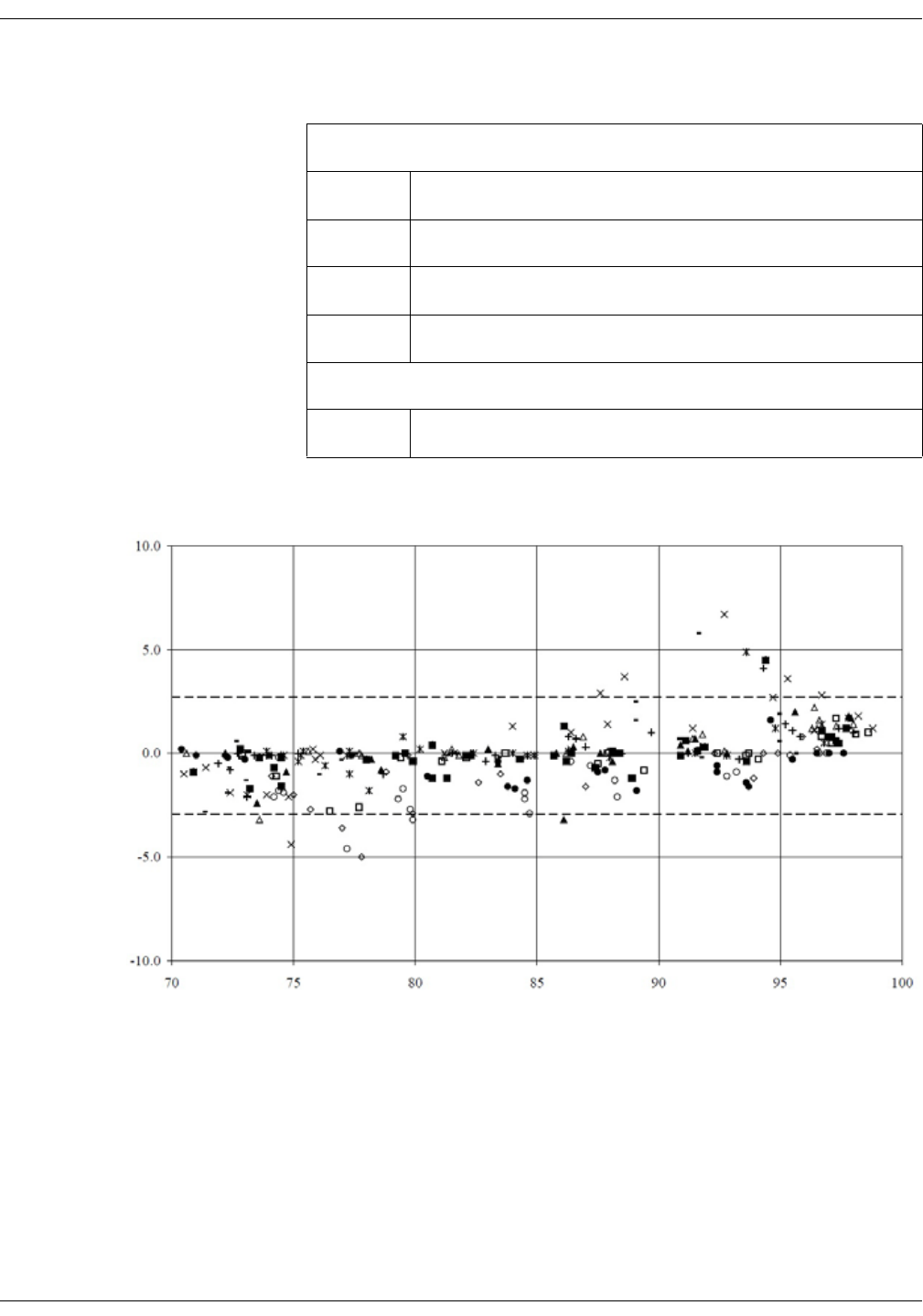
D-10 VC150 Vital Signs Monitor KO00065K
Supplemental analysis of clinical accuracy test data: Masimo sensor accuracy
M-LNCS/LNCS/LNOP - Adtx/Pdtx
M-LNCS/LNCS/LNOP - Adtx/Pdtx, measured values
Range Arms
90-100% 1.64%
80-90% 1.07%
70-80% 1.55%
Overall Claimed Accuracy Value
70-100% ± 2%
SaO2
Error (SpO2 - SaO2 )
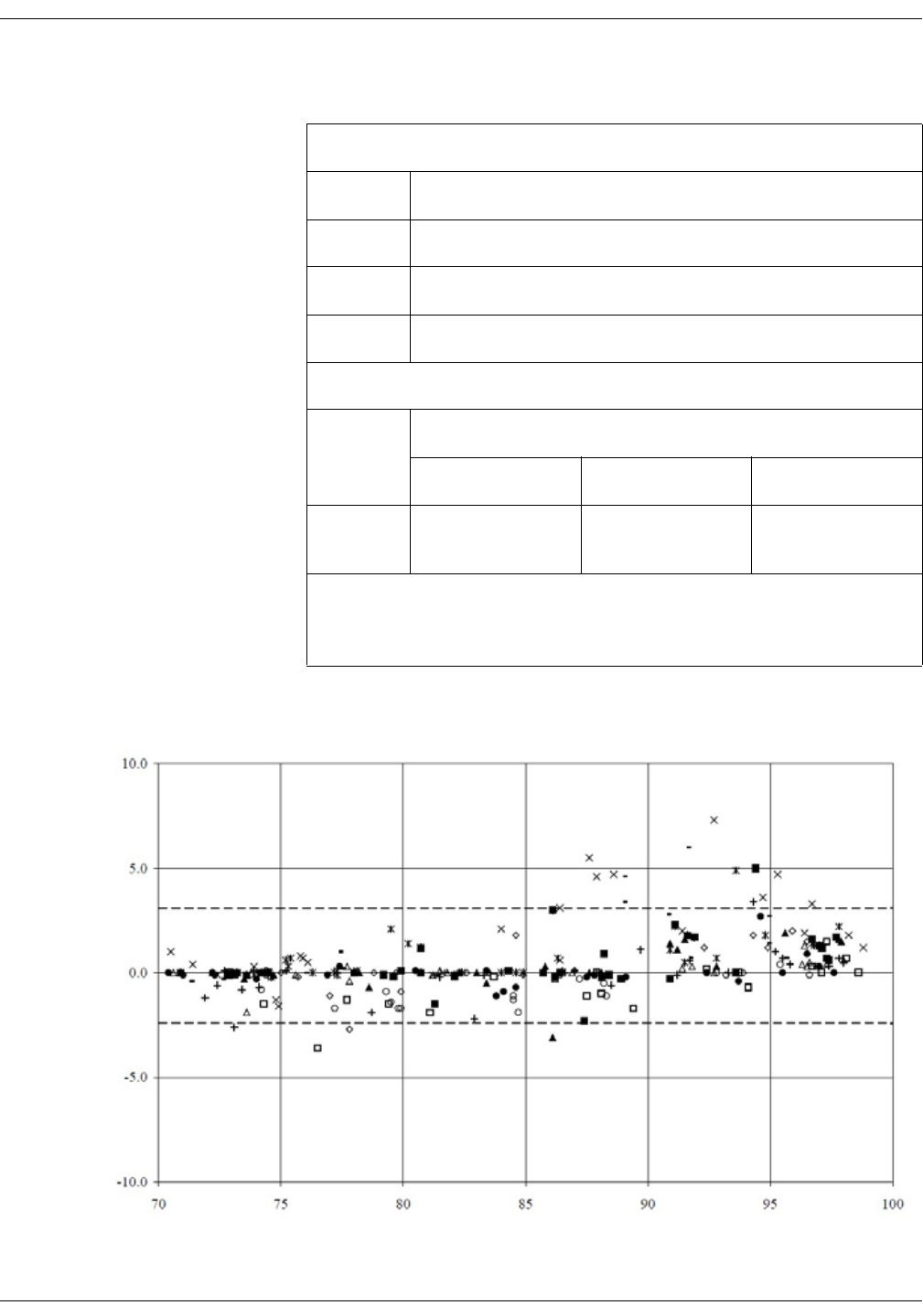
KO00065K VC150 Vital Signs Monitor D-11
Supplemental analysis of clinical accuracy test data: Masimo sensor accuracy
M-LNCS/LNCS/LNOP - Inf/Neo/NeoPt
M-LNCS/LNCS/LNOP - Inf/Neo/NeoPt, measured values
Range Arms
90-100% 1.85%
80-90% 1.44%
70-80% 0.89%
Overall Claimed Accuracy Value
Range Arms
Inf Neo* Neo Pt*
70-100% ± 2% ± 2% Adult
± 3% Neonatal
± 3%
*The saturation accuracy of the Neonate and Preterm sensors was validated
on adult volunteers and 1% was added to account for the properties of fetal
hemoglobin.
SaO2
Error (SpO2 - SaO2 )
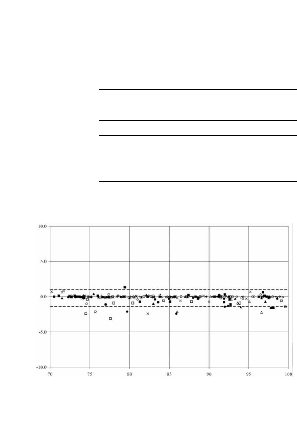
D-12 VC150 Vital Signs Monitor KO00065K
Supplemental analysis of clinical accuracy test data: Masimo sensor accuracy
M-LNCS/LNCS/LNOP DCI and DCIP
Table information provides Arms values measured using the M-LNCS/LNCS/
LNOP DCI and DCIP sensors with Masimo SET Oximetry Technology in a clinical
study.
SaO2 versus error (SpO2 - SaO2) with linear regression fit and upper 95% and
lower 95% limits of agreement.
M-LNCS/LNCS/LNOP - DCI and DCIP, measured values
Range Arms
90-100% 0.6%
80-90% 0.5%
70-80% 0.7%
Overall Claimed Accuracy Value
70-100% ± 2%
SaO2
Error (SpO2 - SaO2 )
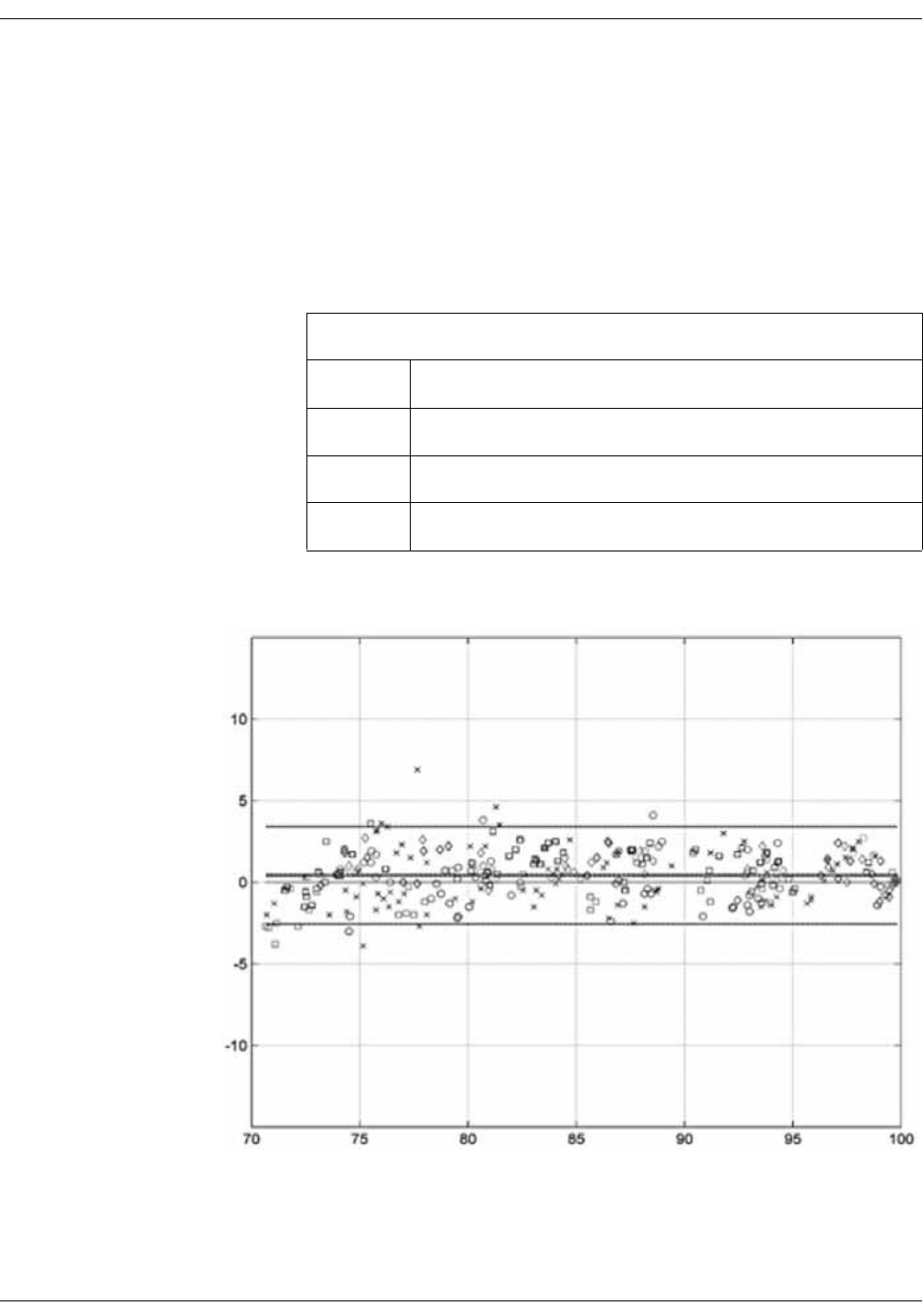
KO00065K VC150 Vital Signs Monitor D-13
Supplemental analysis of clinical accuracy test data: Masimo sensor accuracy
Performance specifications for Rainbow ReSposable Pulse CO-Oximeter
Sensor System
Rainbow Adhesive and Resposable Sensors
The table below shows Arms (Accuracy Root Mean Square) values measured
using the Rainbow Adhesive and Resposable Sensors sensors with Masimo SET
Oximetry Technology in a clinical study.
Rainbow Adhesive and Resposable Sensors, measured values
Range Arms
90-100% 1.25%
80-90% 1.45%
70-80% 1.94%
Error (SpO2 - SaO2 )
SaO2
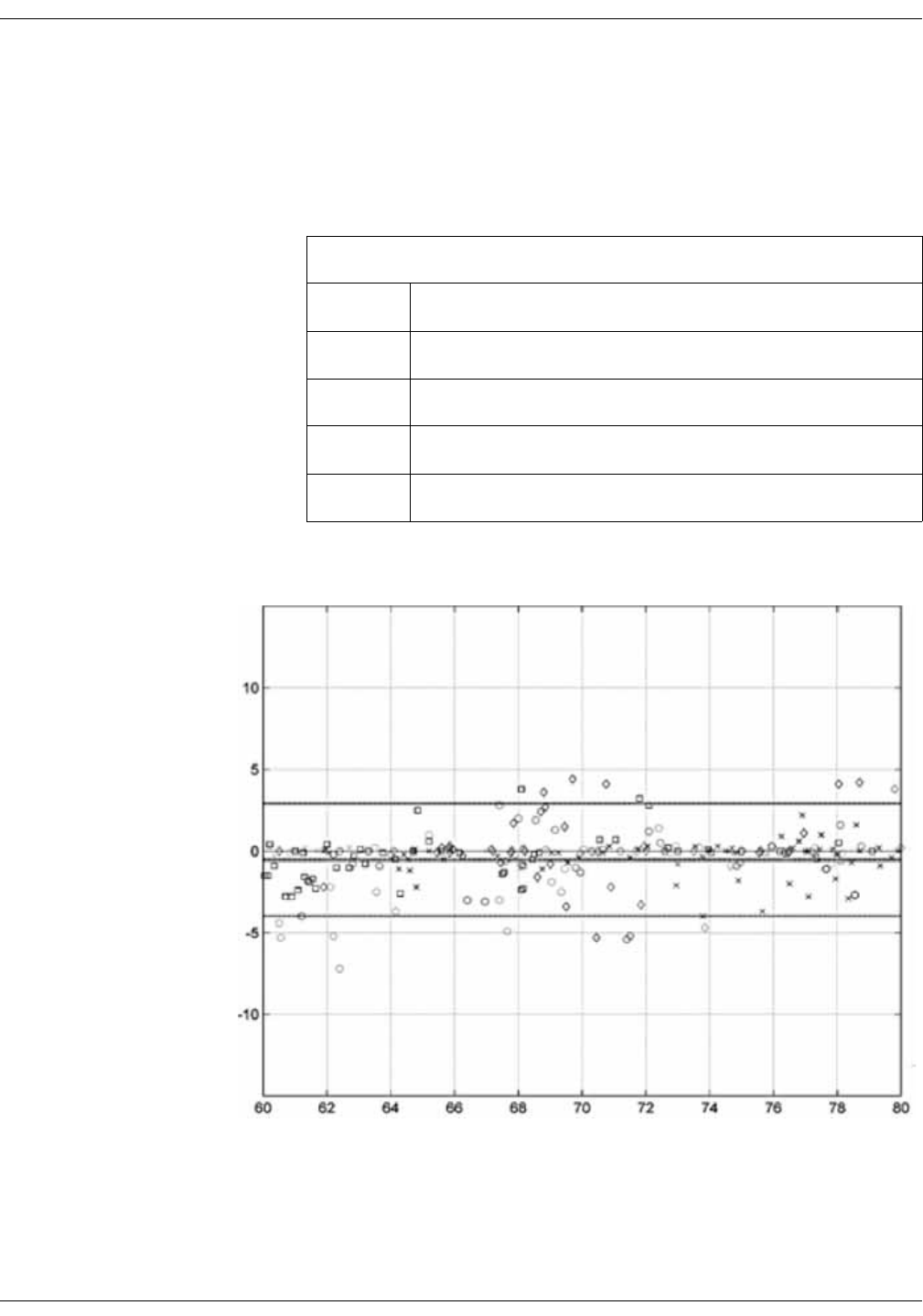
D-14 VC150 Vital Signs Monitor KO00065K
Supplemental analysis of clinical accuracy test data: Masimo sensor accuracy
Rainbow DCI and DCIP Sensors
The table below shows Arms (Accuracy Root Mean Square) values measured
using the rainbow DCI and DCIP sensors with Masimo SET Oximetry Technology
in a clinical study. For accuracy in the range of 70% - 100% please see “M-LNCS/
LNCS/LNOP DCI and DCIP” on page D-12.
Rainbow DCI and DCIP, measured values
Range Arms
75-80% 1.56%
70-75% 1.67%
65-70% 1.86%
60-65% 2.13%
Error (SpO2 - SaO2 )
SaO2
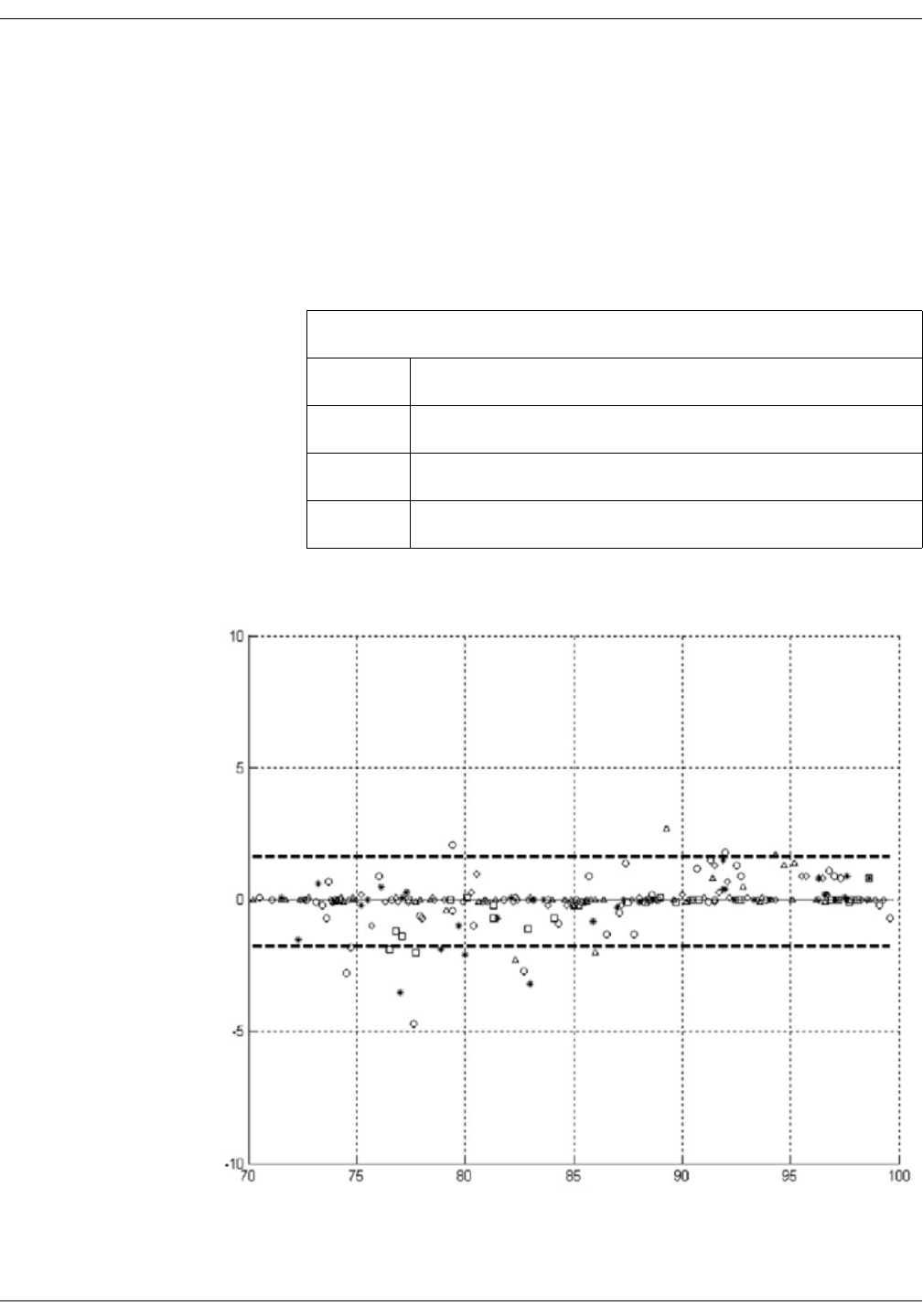
KO00065K VC150 Vital Signs Monitor D-15
Supplemental analysis of clinical accuracy test data: Masimo sensor accuracy
Performance Specifications for Masimo Sensors SpO2 Multisite Reusable
Sensors
The table below shows Arms (Accuracy Root Mean Square) values measured
using the M-LNCS™/LNCS®/LNOP® Multisite sensors with Masimo SET Oximetry
Technology in a clinical study.
M-LNCS™/LNCS®/LNOP® Series
M-LNCS™/LNCS®/LNOP® Multisite, measured values
Range Arms
90-100% 0.63%
80-90% 0.85%
70-80% 1.04%
SaO2
Error (SpO2 - SaO2 )
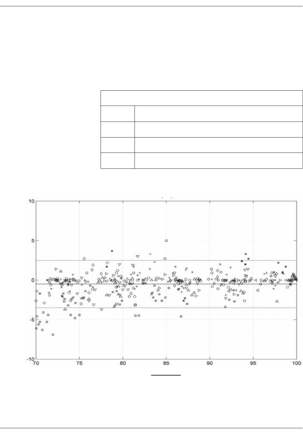
D-16 VC150 Vital Signs Monitor KO00065K
Supplemental analysis of clinical accuracy test data: Masimo sensor accuracy
Performance Specifications for DBI™ Series
DBI Sensors with Masimo SET Oximetry Technology
The table below shows Arms (Accuracy Root Mean Square) values measured
using the DBI reusable sensor with Masimo SET Oximetry Technology in a clinical
study.
DBI Sensors with Masimo SET Oximetry Technology, measured values
Range Arms
90-100% 1.01%
80-90% 1.54%
70-80% 2.06%
SpO2 + SaO2
(SpO2 - SaO2 )
2
This page is intentionally left blank.

Innokas Yhtymä Oy
Vihikari 10
FI-90440 KEMPELE
Finland
Europe
Tel: + 358 8 562 3100
Fax: + 358 8 562 3151
http://www.innokasmedical.fi
Innokas Medical is a subsidiary of
Innokas Yhtymä Oy.
Manufacturer:
0598
