Innovative Control Systems IGWT-662008 S-TAD User Manual Install Manual v2 36 ES IS BR July 2007
Innovative Control Systems Inc S-TAD Install Manual v2 36 ES IS BR July 2007
Contents
- 1. User Manual 1 of 4
- 2. User Manual 2 of 4
- 3. User Manual 3 of 4
- 4. User Manual 4 of 4
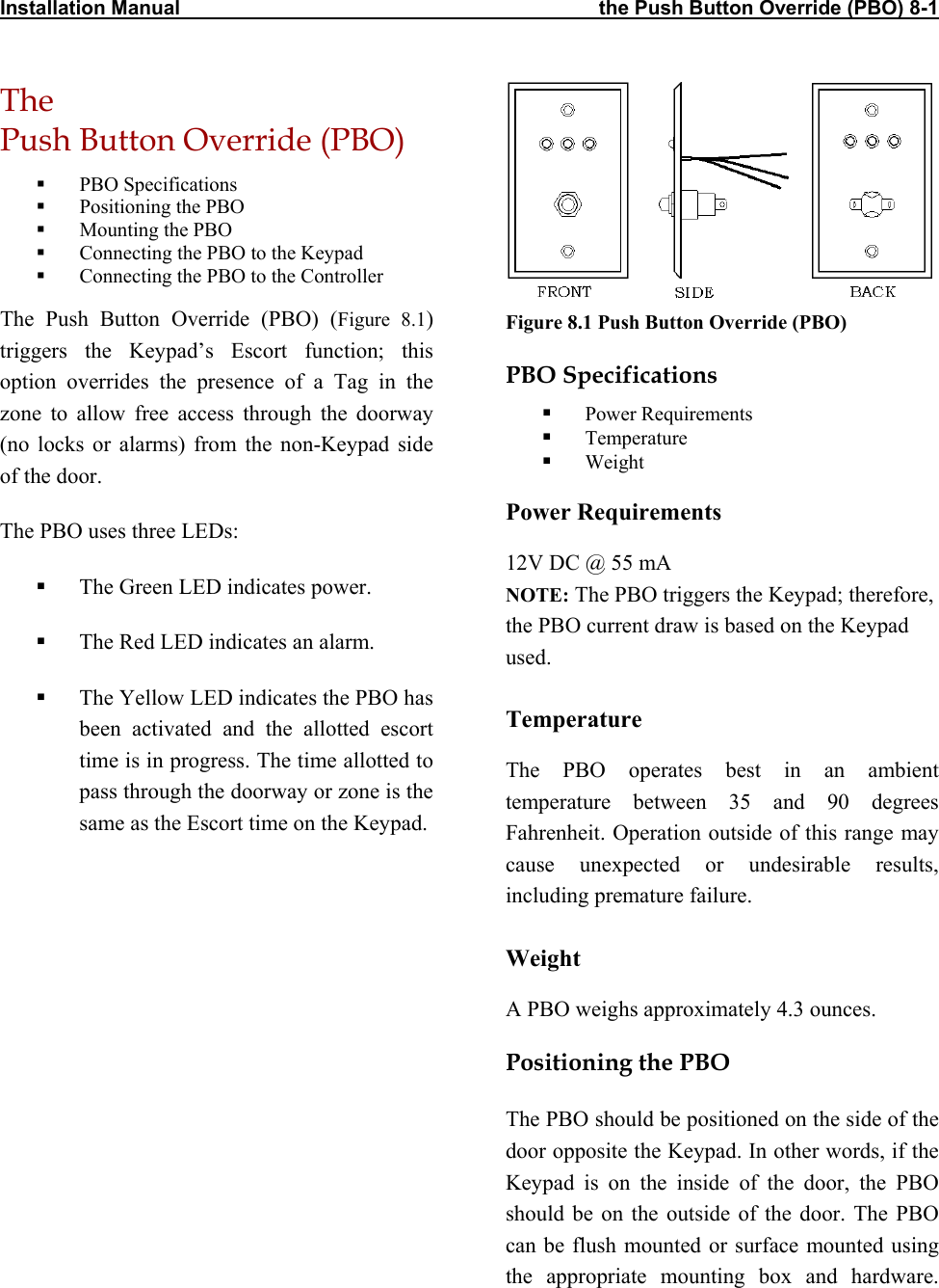
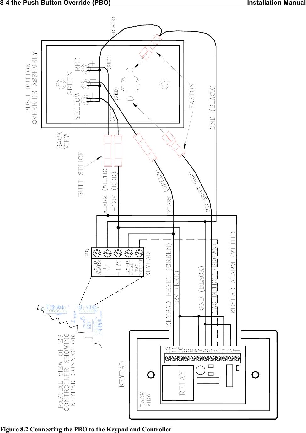
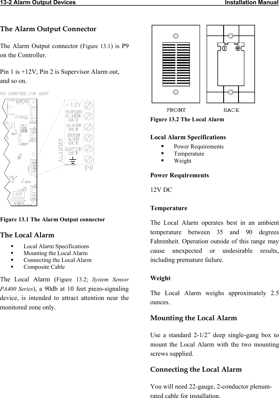
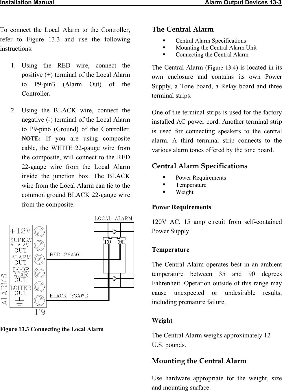
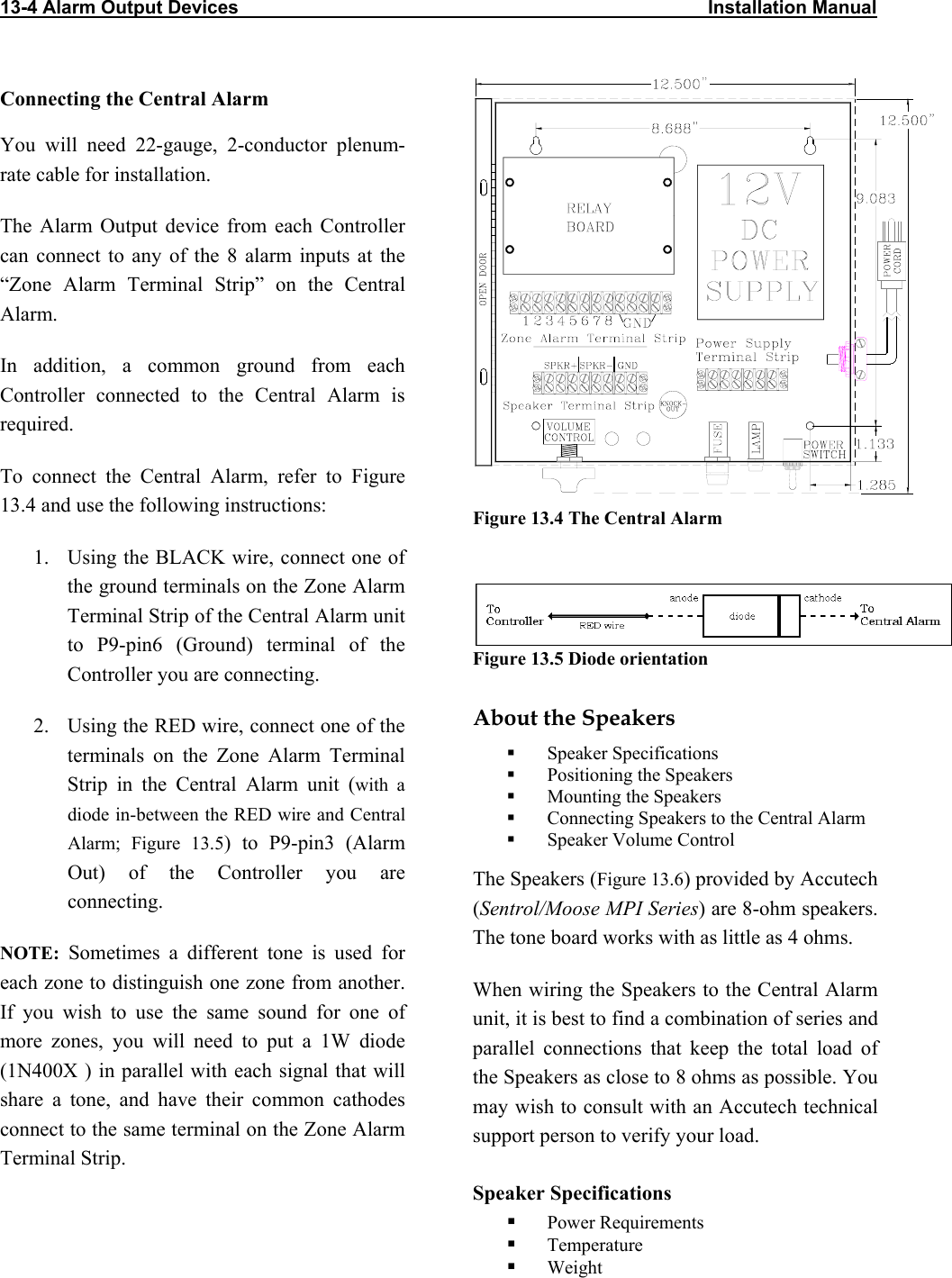
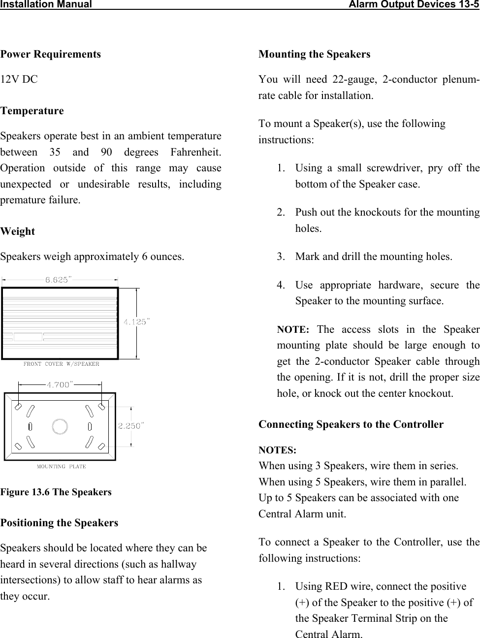
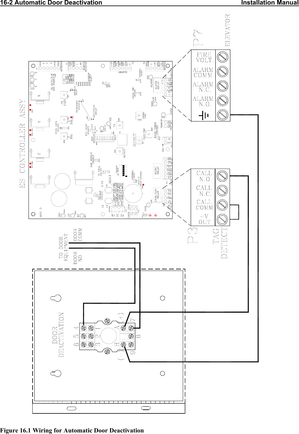
User Manual 2 of 4