Innovative Control Systems IGWT-662008 S-TAD User Manual Install Manual v2 36 ES IS BR July 2007
Innovative Control Systems Inc S-TAD Install Manual v2 36 ES IS BR July 2007
Contents
- 1. User Manual 1 of 4
- 2. User Manual 2 of 4
- 3. User Manual 3 of 4
- 4. User Manual 4 of 4
User Manual 2 of 4

Installation Manual
Chapter 8:
The Push Button Override (PBO)
Installation Manual the Push Button Override (PBO) 8-1
The
Push Button Override (PBO)
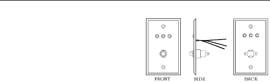
Figure 8.1 Push Button Override (PBO)
PBO Specifications
Positioning the PBO
Mounting the PBO
Connecting the PBO to the Keypad
Connecting the PBO to the Controller
The Push Button Override (PBO) (Figure 8.1)
triggers the Keypad’s Escort function; this
option overrides the presence of a Tag in the
zone to allow free access through the doorway
(no locks or alarms) from the non-Keypad side
of the door.
PBO Specifications
Power Requirements
Temperature
Weight
Power Requirements
The PBO uses three LEDs:
12V DC @ 55 mA
NOTE: The PBO triggers the Keypad; therefore,
the PBO current draw is based on the Keypad
used.
The Green LED indicates power.
The Red LED indicates an alarm.
The Yellow LED indicates the PBO has
been activated and the allotted escort
time is in progress. The time allotted to
pass through the doorway or zone is the
same as the Escort time on the Keypad.
Temperature
The PBO operates best in an ambient
temperature between 35 and 90 degrees
Fahrenheit. Operation outside of this range may
cause unexpected or undesirable results,
including premature failure.
Weight
A PBO weighs approximately 4.3 ounces.
Positioning the PBO
The PBO should be positioned on the side of the
door opposite the Keypad. In other words, if the
Keypad is on the inside of the door, the PBO
should be on the outside of the door. The PBO
can be flush mounted or surface mounted using
the appropriate mounting box and hardware.

8-2 the Push Button Override (PBO) Installation Manual
Mounting the PBO
The PBO is designed to be surface mounted
using the back box provided.
To surface mount the PBO use the following
instructions:
1. Using a screwdriver, separate the PBO
from the back box.
2. Push out the back knock-out.
3. Using the back box as a template, mark
the mounting holes.
4. Drill the necessary holes in the
mounting surface.
5. Secure the back box to the mounting
surface with appropriate hardware.
6. Make any and all wire connections that
require the PBO to be unmounted.
7. Replace the PBO to the back box.
Connecting the PBO to the Keypad
You will need 22 AWG, 4 –conductor Plenum-
rated cable for installation.
NOTE: The following instructions assume that
the Keypad and Controller are already wired.
See Chapter 7, page 7-4 for these instructions.
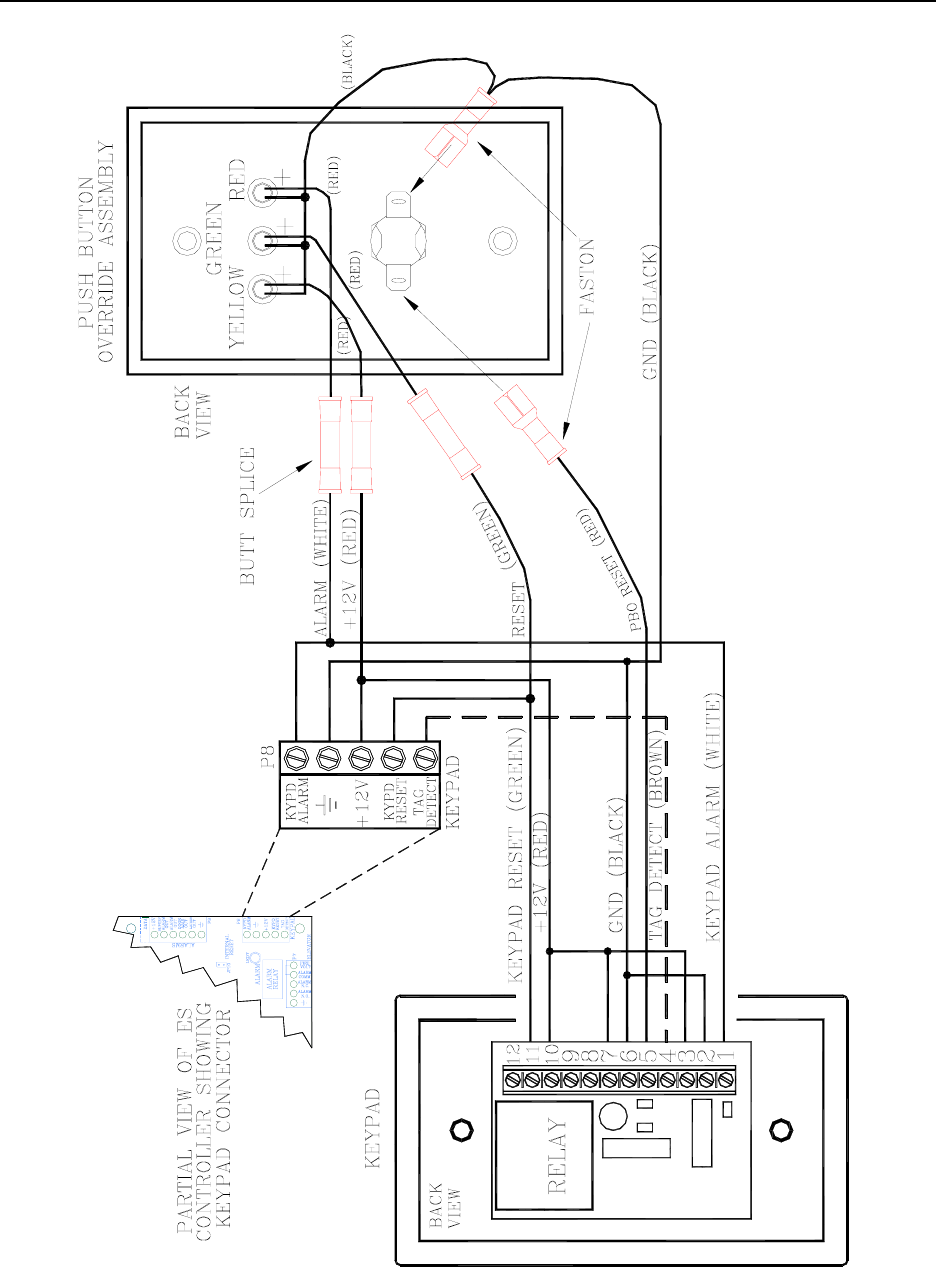
To connect the PBO to the Keypad, refer to
Figure 8.2 and use the following instructions:
1. Remove the Keypad from the white
back box.
2. Remove the Controller cover.
3. Using the RED wire, connect (with a
spade crimp connector) the left prong of
the PBO plug to pin 5 of the Keypad.
4. Using the GREEN wire, connect (with a
butt splice) the positive (+) of the Green
LED to the GREEN wire that connects
the Keypad and the Controller.

Installation Manual the Push Button Override (PBO) 8-3
Connecting the PBO
to the Controller
You will need 22 AWG, 4 –conductor Plenum-
rated cable for installation.
NOTE: The following instructions assume that
the Keypad and Controller are already wired.
See Chapter 7, page 7-4 for these instructions.
To connect the PBO to the Keypad and
Controller, refer to Figure 8.2 and use the
following instructions:
1. Remove the Keypad from the white
back box.
2. Remove the Controller cover.
3. Jumper all negatives (-) of the three
LEDs together, then to the right prong
of the PBO plug (with a spade crimp
connector), and finally to the BLACK
wire that connects the Keypad to the
Controller.
4. Using RED wire, connect the positive
(+) of the Red LED to the RED wire
that connects the Keypad and the
Controller.
5. Using the GREEN wire, connect the
positive (+) of the Yellow LED to the
GREEN wire that connect the Keypad
and the Controller.
6. Using the WHITE wire, connect (using
a butt splice) the positive (+) of the Red
LED to the WHITE wire that connects
the Keypad and the Controller.
8-4 the Push Button Override (PBO) Installation Manual
Figure 8.2 Connecting the PBO to the Keypad and Controller

Installation Manual
Chapter 9:
The Magnetic Switch
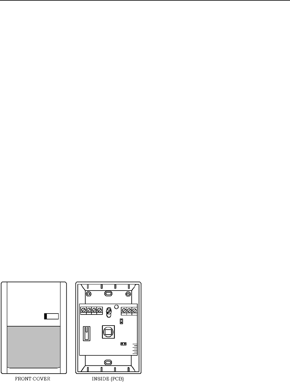
Installation Manual the Magnetic Switch 9-1
The Magnetic Switch
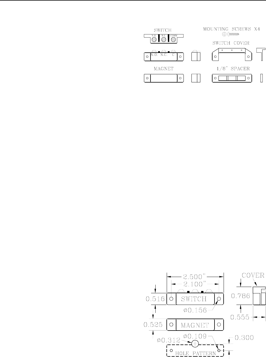
Figure 9.1 Magnetic Switch parts
Magnetic Switch Specifications
Positioning the Magnetic Switch
Mounting the Magnetic Switch
Connecting to the Controller
Double Door Applications
Door Ajar delay time
Door Ajar Reset
Magnetic Switches (Figures 9.1-9.2; GRI 29
Series) are used on doors where alarm activation
is not desired unless the door is opened when a
Tag is in the Tx Activation Field.
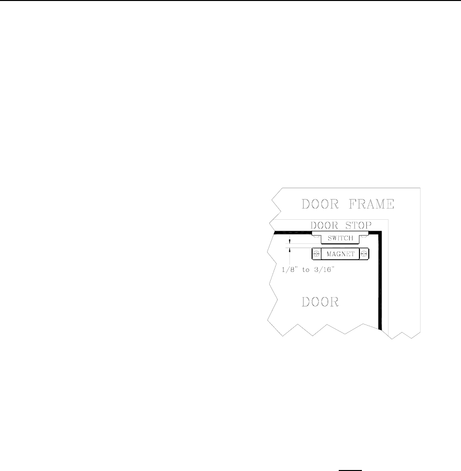
Positioning the Magnetic Switch
Magnetic Switches are usually located at the top
of the monitored door on the doorstop. The part
that contains the Switch is mounted on the
header or doorframe, while the part that contains
the activating Magnet is mounted on the door
itself (see Figure 9.3). A recessed model is also
available.
Magnetic Switch Specifications
Power Requirements
Temperature
Weight
Power Requirements
No power required;
dry contacts rated for 175V DC
For simplicity, in this manual the term
“Magnetic Switch” will reference the entire
Switch as a unit, not just the parts that contain
the contacts.
Temperature
Magnetic Switches operate best in an ambient
temperature between 35 and 90 degrees
Fahrenheit. Operation outside of this range may
cause unexpected or undesirable results,
including premature failure.
Position the Magnetic Switch so that it is nearest
the latch side of the door. If a Magnetic Lock is
used, mount the Switch closest to the latch side
and then the Lock immediately after it.
Figure 9.2 Magnetic Switch Dimensions
Weight
A Magnetic Switch weighs approximately 1.0
ounce.
9-2 the Magnetic Switch Installation Manual
7. While positioning the Switch, insert a
mounting screw through each hole and
secure the Switch in place.
NOTE: Be careful not to pinch the wires
when tightening.
Mounting the Magnetic Switch
To mount the Magnetic Switch, refer to Figure
9.3 and use the following instructions:
1. After choosing your location, following
the hole pattern shown in Figure 9.2,
drill two 7/64” (0.109) mounting holes
in the doorframe to accommodate the
Switch. This size hole also coincides
with the self-tapping screws provided
with the Switch. Be careful not to drill
these holes oversize.
8. Using the spacer provided in the kit,
position the Door Magnet as shown in
Figure 9.3 and mark where the mounting
holes (7/64”) will be drilled.
2. Drill a 5/16” (0.312) pass-through hole
in the doorframe to accommodate the
wire from the Controller to the Switch.
NOTE: This door frame hole should be
drilled so that the wire will come up just
under the middle screw terminal (N.C.)
of the switch. This hole can be drilled a
little smaller, but not larger. If this hole
is drilled too far out from the body of
the Switch, then the Switch cover will
not be able to hide this hole. Be sure to
“de-burr” this hole.
Figure 9.3 Mounting the Magnetic Switch
9. After you have marked and drilled your
holes, mount the magnet with the 1/8”
spacer in between the magnet and the
door.
NOTE: Remember, if the door frame is
metal, you must install the spacer in
between the magnet and the door or the
magnet will lose effectiveness.
3. Fish the 2-conductor/22-gauge wire
through the large hole and strip enough
insulation to make a good connection to
the switch.
4. Connect the RED wire to the “COM”
terminal of the Switch.
5. Connect the BLACK wire to the “N.O.”
terminal of the Switch.
6. Gently guide the excess cable back
through the hole in the frame, while
moving the Switch into position over its
mounting holes.
Installation Manual the Magnetic Switch 9-3
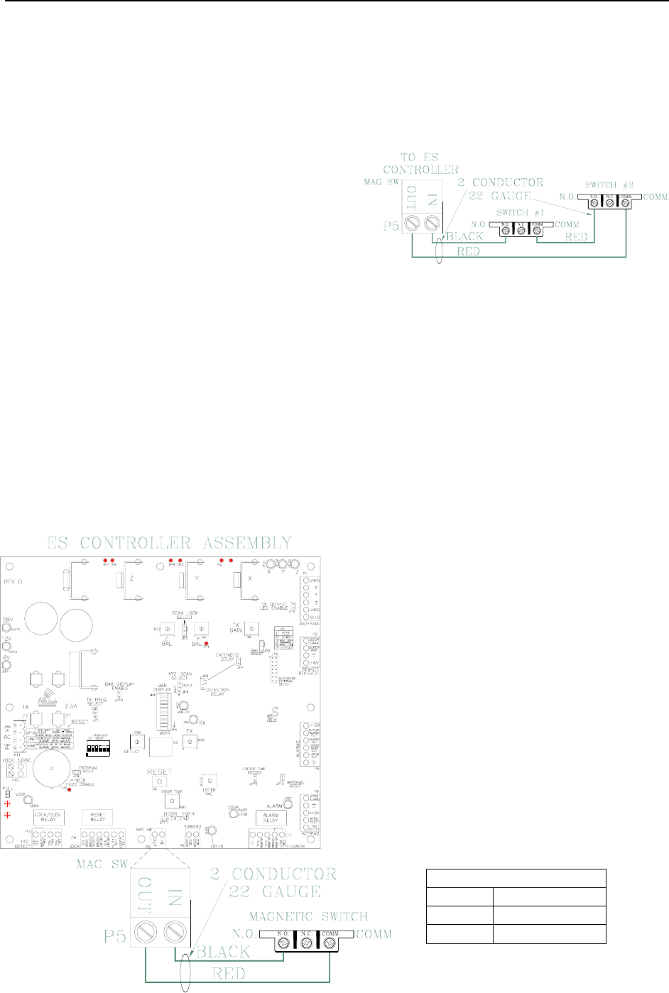
Connecting to the Controller
To connect the Magnetic Switch to the
Controller, refer to Figure 9.4 and use the
following instructions:
1. Using the RED wire, connect “COM”
on the Switch terminal to “OUT” (P5-1)
on the Controller.
2. Using the BLACK wire, connect
“N.O.” on the Switch terminal to “IN”
(P5-2) on the Controller.
NOTE:
If composite cable is used, from the junction box
to the Switch use RED and BLACK colored
wires. From the junction box to the Controller,
use composite cable and follow the wire color
code outlined in Chapter 2.
Figure 9.4
Connecting the Magnetic Switch to the Controller
Double Doors Applications
For double doors applications, connect the
Switches in series (Figure 9.5) so that one
Switch will open when either door is opened.
Figure 9.5
Connecting Two Magnetic Switches in Series
Door Ajar delay time
A Door Ajar alarm occurs when a door is open
for longer than the preset time. By setting a
delay using R97 and JP11, you can adjust the
time (from 10 to 110 seconds) necessary before
a Door Ajar alarm occurs preventing nuisance
Door Ajar alarms from air flow or slight bumps
to the door.
R97 (Door Ajar Delay)
Factory Set to 15 seconds
Set mid scale or as desired to delay onset of
Door Ajar alarm.
JP11 (Door Timer Extend Disable)
Factory Installed IN
This jumper (Table 9.1) determines the timing
range of the Door Ajar Time potentiometer
(R97).
Table 9.1 JP11 Settings
Position Time Range
In 10-60 seconds
Out 65-110 seconds

9-4 the Magnetic Switch Installation Manual
Door Ajar Reset
JP16 (Table 9.2) determines if the Door Ajar
automatically resets once the door is fully
closed.
Table 9.2 JP16 Settings
Position Door Ajar Automatically Resets?
In Yes
Out No

Installation Manual
Chapter 10:
The Passive Infrared Reader (PIR)
Installation Manual the Passive Infrared Reader (PIR) 10-1
The
Passive Infrared Reader (PIR)
PIR Specifications
Power Requirements
Temperature
PIR Specifications Weight
Positioning the PIR
Mounting the PIR Power Requirements
Connecting the PIR
Adjusting the PIR beam angle 12V DC; contact rating: 100 mA @ 24V DC
PIR “Masking”
Passive Infrared Readers (PIRs) (Figure 10.1) are
sensitive to changes in infrared energy caused by
an object moving across a PIR’s field of view.
Detection depends on the difference between the
infrared energy trasmitted by the moving object
and the temperature of background objects.
Temperature
A PIR operates best in an ambient temperature
between 35 and 90 degrees Fahrenheit.
Operation outside of this range may cause
unexpected or undesirable results, including
premature failure.
The PIR Accutech provides (DSC Bravo Series)
is for indoor use only. Its intended use is to
detect movement through doors, corridors, and
passageways. The relay contacts provided by the
PIR (which control detect validation) can be set
to trigger on programmable timer between a
duration of 1 to 7 seconds.
Weight
A PIR weighs approximately 2.8 ounces.
A typical use for a PIR is a hallway, where there
is no door to mount a Magnetic Switch to, or an
elevator, where placing anything on the door or
frame of the car might be undesirable.
Figure 10.1 The Passive Infrared Reader (PIR)
10-2 the Passive Infrared Reader (PIR) Installation Manual
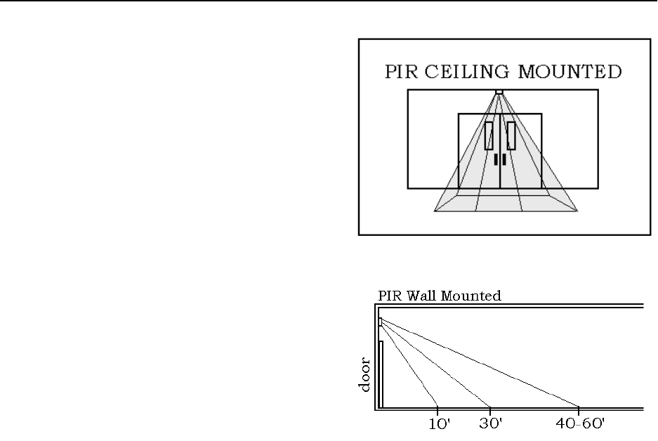
Positioning the PIR
Position the PIR to have the best coverage
possible for your situation.
Accutech recommends ceiling mounting the PIR
(Figure 10.2) to assure complete and focused
coverage of the opening.
Wall mounting the PIR may result in detection
beyond the desired area (Figure 10.3). If you
decide to wall mount the PIR, “mask” the PIR to
reduce the range.
Figure 10.2 Ceiling-mounted PIR
While positioning the PIR, keep in mind:
The more precisely you place and focus
the PIR, the less likely you are to get a
nuisance alarm on a simple pass-by
instead of a true egress.
Figure 10.3 Wall-mounted PIR
The maximum coverage area of a PIR
wall-to-wall curtain is 50’L x 60’W. Mounting the PIR
To mount the PIR, refer to Figure 10.1-10.3 and
use the following instructions:
The PIR must be must be pointed at an
object (e.g., the floor) to be able to
detect. 1. Push in the tab at the bottom of the case
and pull the cover straight out at the
bottom.
Do not point the PIR at reflective
surfaces such as mirrors or windows as
this may distort the coverage pattern or
reflect sunlight directly into the PIR. 2. Loosen the PCB screw and push the
board up as far as it will go.
When mounting a PIR close to an
elevator, you can avoid nuisance
detection by locating the PIR at an
adequate distance away from the
elevator doors. The movement of air
caused by an operating elevator can
cause nuisance PIR detection.
3. Using a small screwdriver, remove the
appropriate knockouts for the mounting
screws.
4. Remove the left and/or right wiring
entrance knockouts located at the top of
the backplate.

Installation Manual the Passive Infrared Reader (PIR) 10-3
5. Mount the backplate to the wall using
the screws supplied.
NOTE: For wall and ceiling
installations, use the two knock-outs at
the back of the base. For corner or 45º
mounting use the knock-outs on the
angled sides. The unit must be fastened
securly to the mouting surface to avoid
possibe vibrations.
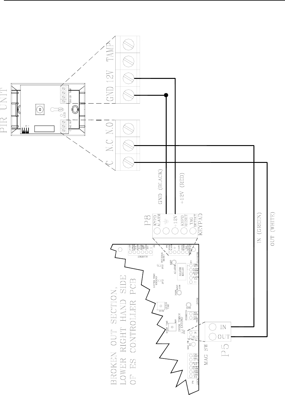
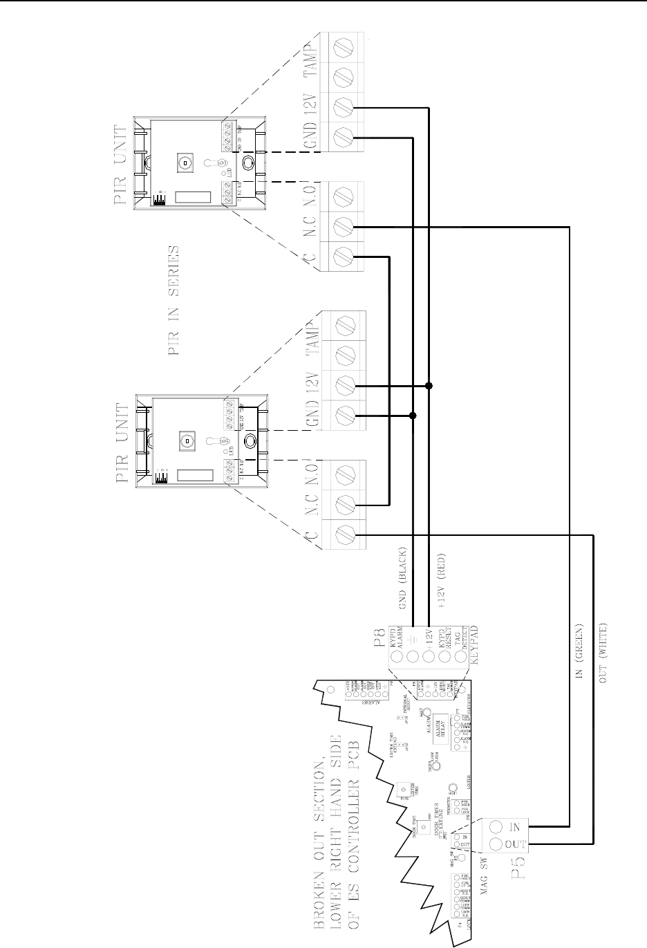
Connecting the PIR
You will need 22 AWG, 4-conductor cable
(supplied with the door wire kit) for installation.
To connect the PIR to the Controller, refer to
Figure 10-4 (or for PIR in series refer to 10-5)
and use the following instructions:
1. Using the WHITE wire, connect ( C )
of the PIR to P5-pin1 (Out) on the
Controller.
2. Using the GREEN wire, connect (N.C.)
of the PIR to P5-pin2 (In) on the
Controller.
3. Using the BLACK wire, connect (GND)
of the PIR to P8-pin2 (Ground) on the
Controller.
4. Using the RED wire, connect (+12V) of
the PIR to P8-pin3 (+12V) on the
Controller.
Adjusting the PIR beam angle
To change the angle of the PIR beam, use the
following instructions:
1. Loosen the PCB screw and move the
board up or down. The scale on the
lower right side of the board indicates
the angle.
2. Moving the PCB down will increase the
far range and move the near beams
farther out from the mounting wall.
3. Moving the PCB up will reduce the far
range and bring the near beams closer to
the mounting wall.
4. When finished adjusting, tighten the
adjustment screw in place.
10-4 the Passive Infrared Reader (PIR) Installation Manual
Figure 10.4 Wiring the PIR to the Controller
Installation Manual the Passive Infrared Reader (PIR) 10-5
Figure 10.5 Wiring PIR in series
10-6 the Passive Infrared Reader (PIR) Installation Manual
PIR “Masking”
If you have adjusted the PIR beam angle and the
area covered is still too large and is overlapping
into undesired areas, use the following
“masking” method to reduce the effective area
of the beams:
1. The PIR has 3 “beams.” The low beam
reaches about 10’, the middle beam
reaches about 30’, and the high beam
can reach 40-60’ (see Figure 10.3).
“Masking” a PIR means covering one or
more of the beams to reduce the PIR’s
range.
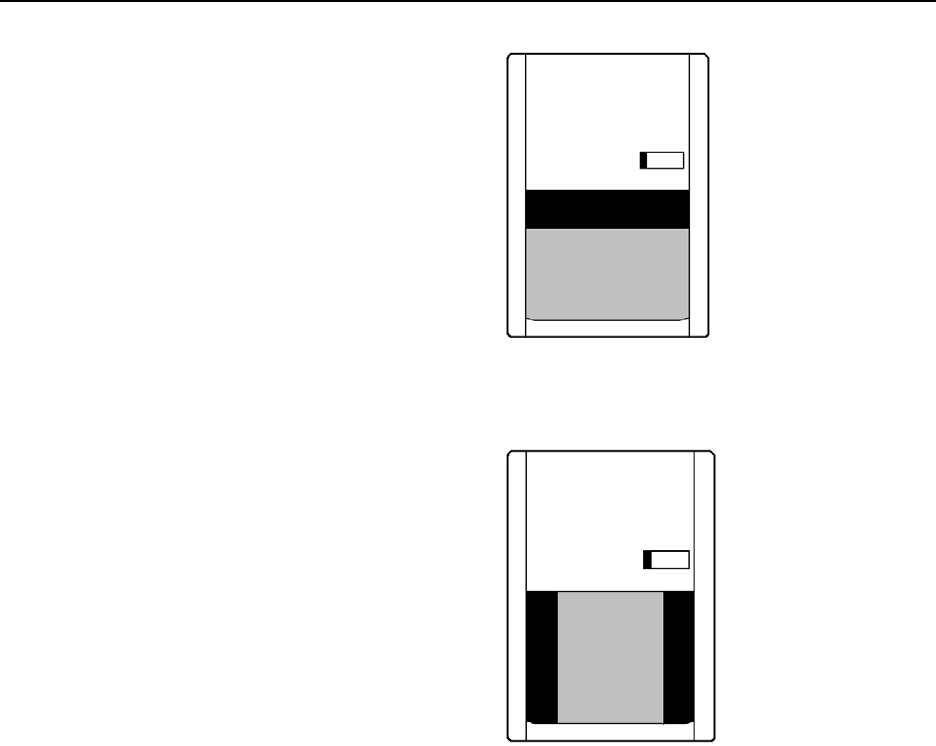
2. Place one strip of electrical tape
horizontally across the top of the PIR
lens (see Figure 10.6); this will cover the
high beam.
3. Test the range of the PIR.
4. If necessary, place another strip of tape
horizontally in the middle of the PIR
lens; this will cover the middle beam.
5. Test the range of the PIR.
6. OPTIONAL: If the PIR is extending too
far outward (to the sides), place stripes
of tape vertically on the sides of the PIR
lens (see Figure 10.7); this will cover all
outward beams producing a narrower
coverage area.
7. Test the range of the PIR.
Figure 10.6 PIR Masking horizontal example
Figure 10.7 PIR Masking vertical example

Installation Manual
Chapter 11:
Magnetic Locks

Installation Manual Magnetic Locks 11-1
Magnetic Locks
Perimeter Door Applications
Operation of the Magnetic Lock
3101 Series Magnetic Locks
3000 Series Magnetic Locks
Each Magnetic Lock is comprised of 3 basic
components: a lock housing, an electromagnetic
coil and an armature.
The coil and housing assembly mounts rigidly to
the door frame while the armature mounts to the
door in a manner that allows it to pivot slightly
to compensate for door irregularities.
When the door is closed and the lock is
energized the armature is magnetically bonded
to the lock face, thus securing the door without
utilizing any moving parts.
JP9 (External Reset) selects which device will
control the resetting of the Lock after it has been
energized (locked). With the jumper in, a
Keypad reset is required to reset the Lock to its
unlocked state. With the jumper out, the Lock
will return to its unlocked state after the time
delay set on switch S1 expires. In either case, all
Tags must be removed from the monitored zone
for the Lock to be reset.
Perimeter Door Applications
The Lock can be used as an Access Control
device. In normal state, the door will be closed
and locked. Entering a valid code into a Keypad
or activating a PBO will open the door. When
closed again, the door will reset after the
adjustable set period of time.
Operation of the Magnetic Lock
The Magnetic Lock will engage when a Tag is
on the Tx Activation Field. The Lock remains
engaged as long as a Tag is in the Field. JP9
(External Reset) selects which device will
control the resetting of the Lock after it has been
energized (locked). With the jumper in, a
Keypad Reset is required to reset the Lock to its
unlocked state. With the jumper out, the Lock
will return to its unlocked state after the time
delay set on switch S1 expires. In either case, all
Tags must be removed from the monitored zone
for the Lock to be reset.
Once locked, the Lock will disengage when any
of the following conditions occur:
All Tags leave the Field and the switch
S1 time delay expires (JP9 must be
out).
A Keypad Reset (JP9 is in).
A PBO is activated.
The facility’s Fire Alarm is activated.
The removal of power, for any reason,
will de-energize the lock allowing the
door to be opened.
The Central Override is activated
(Optional).
3101 ONLY - When a maintained force
(less than 15 pounds required) is
applied to the door for an adjustable
period of time (1 to 3 seconds).

11-2 Magnetic Locks Installation Manual
3101 Magnetic Locks
3101 Magnetic Lock Specifications
Lock Jumper
Mounting the 3101 Magnetic Lock
Connecting the 3101 Magnetic Lock
Connections and Operation
Adjusting the Sensor Pin
Changing the Lock Nuisance delay time
Changing the Egress Alarm delay time
The 3101 Magnetic Lock features 1200 pound
holding force, Delay Egress Circuitry, NFPA101
Life Safety Codes conformity, a selectable
nuisance delay and an Accutech custom-
designed electromagnetic coil.
Our custom-designed electromagnetic coil, only
available through Accutech, results in lower
current draw (only 12V AC/DC required).
3101 Magnetic Lock Specifications
Power Requirements
Temperature
Weight
Power Requirements
12V AC/DC
Temperature
3101 Magnetic Locks operate best in an ambient
temperature between 35 and 90 degrees
Fahrenheit. Operation outside of this range may
cause unexpected or undesirable results,
including premature failure.
Weight
The 3101 Magnetic Lock weighs 11 U.S.
pounds.
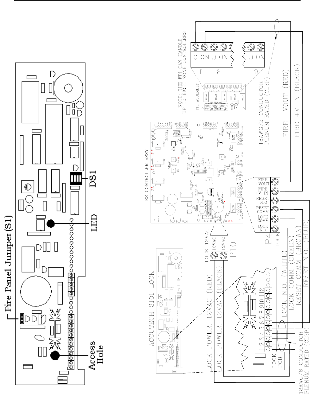
Lock Jumper
The 3101 Lock has one jumper on it, the Fire
Panel Jumper (Figure 11.2). By default it is
placed in position 2-3. You must move this
jumper (and leave it) into position 1-2 (the left
two pins) before you install the Lock.
Mounting the 3101 Magnetic Lock
To mount the 3101 Magnetic Lock, follow the
DynaLock Corp. Mounting and Operating
Instructions that came with the Lock.
Connecting the 3101 Magnetic Lock
IMPORTANT:
Follow the WIRING INSTRUCTIONS in
THIS MANUAL ONLY!
Terminal connections and functions
vary from the locks original design
and documentation.
You will need 18-gauge 6-conductor non-
shielded cable for installation. If you are using
composite cable, see Chapter 2 for color codes.
NOTE:
State codes require that all lock and elevator
deactivation circuitry be wired into the facility’s
fire alarm system (see Chapter 12: Fire Panel
Interface). This is done so that in case of a fire,
any lock or elevator deactivation unit
disengages, allowing for free egress or ingress.
To connect the 3101 Magnetic Lock, consult
Figures 11.1 and 11.2.
Installation Manual Magnetic Locks 11-3
Figure 11.1 3101 Magnetic Lock PCB Figure 11.2 Connecting the 3101 Magnetic Lock

11-4 Magnetic Locks Installation Manual
Connections and Operation
This section quickly explains the functions of
Lock pins 1-6.
Lock Power, pins 1 and 2 require a constant 12-
volt AC/DC which is supplied (AC) by the
Controller at connector P10.
Lock Trigger, at the Controller and upon Tag
detection, the contacts at pins 1 and 2 P4 will
close (Lock N/O. & Lock Comm). When
connected to pins 3 & 4 of the Lock, this will
engage the lock.
Lock Reset, when a reset is initiated, either by
the reset button on the Controller, or an external
reset from either the PBO, or the Keypad, the
contacts at pins 3 and 4 of P4 will close (Reset
Comm & Reset N.O.). When connected to pins 5
& 6 of the Lock, will reset the Lock.
With the Lock engaged, if delayed egress is
initiated and the Tag leaves the Tx Activation
Field before the door is opened, the Lock will
automatically reset after the “Lock Hold timer”
times out. The Lock will not reset is if the door
is opened by anyone during the Lock hold time.
If the door is opened while the Lock is in
delayed egress, or during the Lock Hold time
after the egress sequence is complete, the Lock
will latch into egress and the Keypad must be
reset to return the Lock to its normal non-locked
state.
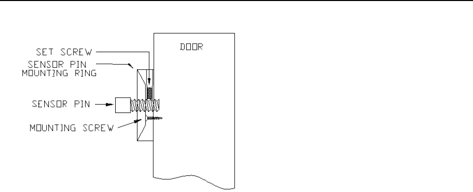
Adjusting the Sensor Pin
Accurate adjusting of the Sensor pin will help
prevent nuisance alarms from slight disturbances
and small vibrations such as someone bumping
into the door or someone shutting a door nearby.
To adjust the Sensor pin, refer to Figures 11.3
and use the following instructions:
1. Remove power from the Lock by
powering down the Controller.
2. Remove the cover to the Lock housing.
3. Remove the Fire Alarm Control jumper
(see Figure 11.2).
4. Make sure DS1 (the Lock selector switch)
Position 3 is in the OFF position
(see Figure 11.2).
5. Move DS1 Position 1 to the ON position
(see Figure 11.2).
NOTE: The ON position denotes “set-
up” mode.
6. Be certain that the Set screw in the
Sensor Ring is loose and will not make
contact with the Sensor pin. (see Figure
11.3)
WARNING: Failure to follow this step
can damage the threads of the Sensor
pin as you make adjustments.
7. Start with the Sensor pin adjusted out as
far as possible while still solidly
threaded into the Sensor ring.
Installation Manual Magnetic Locks 11-5
Figure 11.3 Adjusting the Sensor Pin
8. Apply power to the Lock by powering
up the Controller. The Lock LED will
light up both Green and Red (kind of
Yellow) while it goes through its power
up sequence (about 5 seconds)
(see Figure 11.2).
9. When the power up sequence is over,
the LED will either turn solid Red (Door
closed and locked) or the LED will turn
off (Door open and unlocked). You want
the door to be closed and locked.
10. With the door closed and locked, apply
as much pressure to the door as needed
to fully deflect the door, and while
holding it in this position, adjust the
Sensor pin with the included ¼ Allen
wrench until the (Red) LED goes out on
the Lock.
NOTE: For slight adjustments, there is a
Sensor pin access hole in the PCB of the
Lock (see Figure 11.2) However,
depending on how the internal lock
wires are situated this may not be
feasible. If this is the case, it is
recommended that you deflect the door
farther until you can adjust the Sensor
pin directly with the Allen wrench.
11. When you have completed the
adjustment, gently allow the door to be
pulled by the weight of the door.
NOTE: When the door is closed the
LED will be Red, when the door is open
the LED will be Off.
12. Remove power from the Lock by
powering down the Controller.
13. Tighten the set screw with the Allen
wrench provided. This will prevent the
Sensor pin from coming out of
adjustment.
NOTE: Be careful not to over tighten.
14. Replace the Fire Alarm Control jumper
into the N.C. position (pins 1-2)
(see Figure 11.2).
15. Move DS1 Position 1 into the OFF
position (see Figure 11.2).
NOTE: This will take the lock out of
set-up mode and into normal operation
mode.
16. Move DS1 Position 3 into the ON
position (see Figure 11.2).
17. Replace the cover to the Lock housing.
18. Apply power to the Lock from the
Controller and test the function of the
Lock.
Changing the Lock Nuisance delay time
The Lock Nuisance Delay time prevents
nuisance alarms by requiring a door disturbance
to be sustained for a set length of time before
registering an alarm.

11-6 Magnetic Locks Installation Manual
The delay time is set by Position 3 on the
Selector Switch (S1) on the Lock PCB (see
Figure 11.2).
The OFF position results in a 1-second
delay
The ON position results in a 3-second
delay
Changing the Egress Alarm delay time
The Egress Alarm delay time requires a door
disturbance to be sustained for a set length of
time before unlocking the door and allowing
egress.
The delay time is set by Position 4 on the
Selector Switch (DS1) on the Lock PCB (see
Figure 11.2).
The OFF position results in a 15-
second delay
The ON position results in a 30-second
delay
3000 Magnetic Locks
3000 Magnetic Lock Specifications
Mounting the 3000 Magnetic Lock
Connecting the 3000 Magnetic Lock
Changing the Lock Nuisance delay time
3000 Magnetic Lock Specifications
Power Requirements
Temperature
Weight
Power Requirements
12V or 24V AC/DC
Temperature
3000 Magnetic Locks operate best in an ambient
temperature between 35 and 90 degrees
Fahrenheit. Operation outside of this range may
cause unexpected or undesirable results,
including premature failure.
Weight
The 3000 Magnetic Lock weighs 9 U.S. pounds.

Installation Manual Magnetic Locks 11-7
Mounting the 3000 Series Magnetic Lock
To mount the 3000 Magnetic lock, follow the
DynaLock Corp. Mounting and Operating
Instructions that came with the Lock.
NOTE: State codes require that all lock and
elevator deactivation circuitry be wired into the
facility’s fire alarm system. This is done so that
in case of a fire, any lock or elevator
deactivation unit disengages, allowing for free
egress or ingress. Be sure to check Local, State
and Federal Codes as well as Chapter 12: Fire
Panel Interface (FPI).
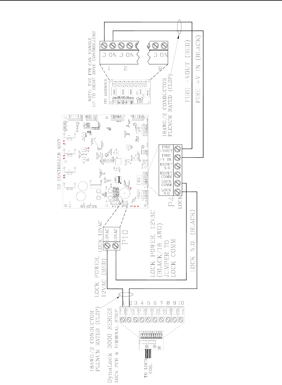
Connecting the 3000 Series Magnetic Lock
You will need 18-gauge 2-conductor non-
shielded cable to make your connections.
The basic operation of this Lock will center on
supplying power to the Lock coil whenever a
Tag is detected in the zone, and removing that
power when there are no Tags detected in the
zone.
To connect the 3000 Series Magnetic Lock to
the Controller, refer to Figure 11.4 and use the
following instructions:
At the Lock:
1. Connect the RED wire to pin 1 on the
Lock terminal strip.
2. Connect the BLACK wire to pin 2 on
the Lock terminal strip.
At the Controller:
1. Connect the open end of the RED wire
to pin 1 (+12V AC) of P10.
NOTE: This will provide half of the AC
power connection for the Lock.
Furthermore, the Lock Trigger contacts
at the Controller will close upon Tag
detection. By using these contacts, you
can open and close the other half of the
AC power connection for the lock.
2. Connect the open end of the BLACK
wire to pin 1 (Lock N.O.) of P4.
NOTE: This contact will close whenever
there is Tag detection.
3. Using a short piece of BLACK wire,
connect one end to pin 2 (+12V AC) of
P10 to pin 2 (Lock Comm) of P4.
4. Make your connections from the Fire
Panel to pins 5 & 6 of P4.
5. Apply power to the Controller and test
the Lock.
Changing the Lock Nuisance delay time
The Lock Nuisance Delay time prevents
nuisance alarms by requiring a door disturbance
to be sustained for a set length of time before
registering an alarm.
The delay time is set by Position 3 on the
Selector Switch (S1) on the Lock PCB (see
Figure 11.3).
The OFF position results
in a 1-second delay
The ON position results
in a 3-second delay
11-8 Magnetic Locks Installation Manual
Figure 11.4 Connecting the 3000 Magnetic Lock

Installation Manual
Chapter 12:
Fire Panel Interface (FPI)
Installation Manual Fire Panel Interface (FPI) 12-1
Fire Panel Interface (FPI) In addition, the FPI unit can provide:
FPI Specifications An Optional Central Override, which
allows the facility to disable all Locks
and/or Elevator Deactivation units
controlled by that FPI. Each FPI
requires its own override switch.
Positioning the FPI
Before Connecting the FPI
Connecting the FPI to the Controller
State codes require that all Lock and Elevator
Deactivation Circuitry be wired into the
facility’s fire alarm system. A Manual Reset, which will re-engage
the Locks and/or Elevator Deactivation
units after the fire alarm is reset. This
switch can be replaced with a jumper
that will make the reset process
automatic once the fire alarm is reset.
This is done so that in case of a fire, any Lock or
Elevator Deactivation unit disengages, allowing
for free egress or ingress. For more information
on this policy, check your local codes.
For each FPI unit (Figure 12.1) used, you will
need one set of dry contacts from the facility’s
fire panel. Each FPI unit provides dry contact
outputs for up to 8 Controllers.
An Auxiliary Output (+12VDC) for
alerting staff that the Locks and/or
Elevator Deactivation units are
disengaged. This is typically connected
to the Staff Alert or Graphic Panel(s).
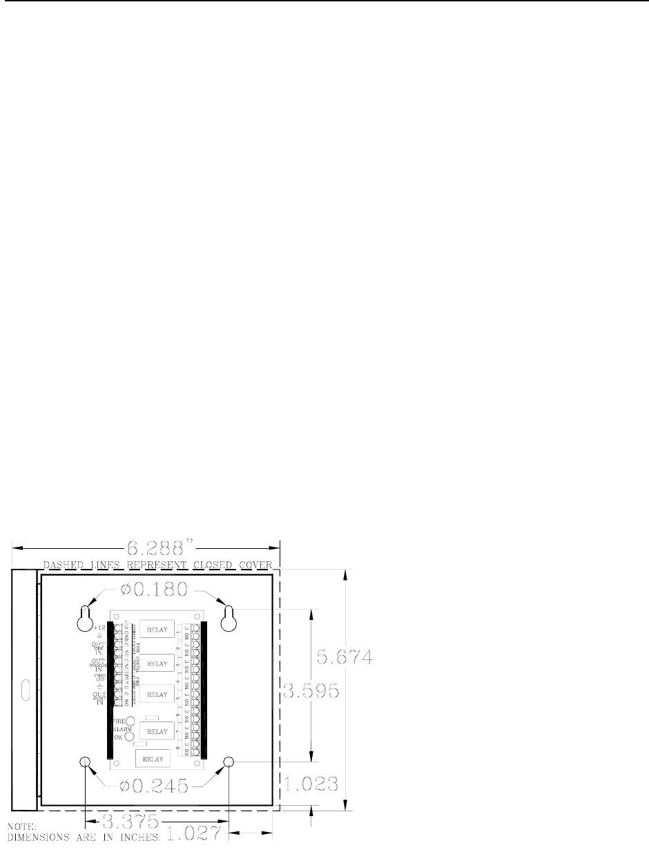
Figure 12.1 The FPI with cabinet

12-2 Fire Panel Interface (FPI) Installation Manual
FPI Specifications
Power Requirements
Temperature
Weight
Power Requirements
12V DC
Temperature
The FPI operates best in an ambient temperature
between 35 and 90 degrees Fahrenheit.
Operation outside of this range may cause
unexpected or undesirable results, including
premature failure.
Weight
The FPI (including cabinet) weighs
approximately 1 pound.
Positioning the FPI
The FPI can be located:
Near a GDP
Near a Nurse Station
Near a Multiplexer
In an equipment room
Before Connecting the FPI
Verifying the Fire Alarm Dry Contacts
The facility must provide an unused dry contact
in the fire alarm system for each FPI unit. (This
contact must be closed during a non-alarm state
and must OPEN in case of a fire alarm or loss of
fire alarm function.)
Verifying the Fire Alarm Dry Contacts
CAUTION: Before you test the system, notify
the facility and the local fire department that you
will be testing the fire alarm system.
To verify the operation of the fire alarm dry
contacts, use the following instructions:
1. Connect an ohmmeter across the dry
contacts. There should be continuity in
the non-alarm state. (Contact should be
closed.)
NOTE: There should never be voltage
on this contact.
2. Trip the fire alarm to verify that the
contacts change state. You should now
see an OPEN on your meter.
3. Reset the fire alarm and verify the
contacts go back to their closed state.

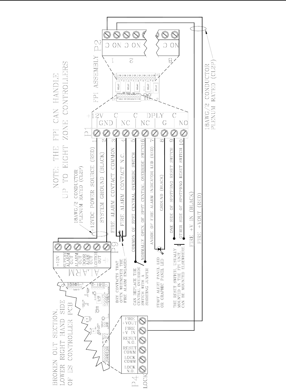
Installation Manual Fire Panel Interface (FPI) 12-3
Connecting the FPI
Pins 1 and 2
Pins 3 and 4
Pins 5 and 6
Pins 7 and 8
Pins 9 and 10
Because of the variety of possible mounting
locations, and therefore distances between
signals and sources, it is recommended that you
use no less than 18-gauge plenum-rated wire and
cable for connecting the FPI unit.
You must use a separate dry contact for each
Controller that controls a Lock or Elevator
Deactivation unit.
This dry contact may come directly from the
facility’s fire panel, or from the
Accutech Fire Panel Interface (FPI) unit. The
FPI unit will allow you to connect multiple
Controllers to the facility fire panel. (See
Figures 12.1-12.2)
To connect the FPI to the Controller, refer to
Figure 12.2 and use the following information
about the FPI pins:
Pins 1 and 2 (Power)
You will need a separate 2-conductor cable run
from one of the ES units to supply power (+12V
DC) and ground to the pins 1 & 2, respectively.
At the Controller, you can use either the Alarms
terminal (P9) or the Keypad terminal (P8) as
your source for these signals.
Pins 3 and 4 (Fire Voltage)
The dry contacts from the fire panel connect to
pins 3 (“C”) and 4 (“NC”) of P1 on the FPI. Pin
3 is simply +12V DC that is sent out through the
fire alarm contacts. Pin 4 is the return of the
voltage and should only be present when the fire
alarm system is working properly and the fire
alarm is not engaged.
Pins 5 and 6 (Central Override)
Pins 5 (“C”) & 6 (“NC”) of P1 on the FPI are for
the Central Override contacts.
If this option is not used, you will see a
shorting jumper between these two
points or you need to place one.
When using more than one FPI, each
FPI should have its own shorting
jumper or central override switch.
Pins 7 and 8 (Fire Alarm Indicator)
Pins 7 (“DPLY”) & 8 (“G”) of P1 on the FPI are
the Auxiliary Output that are typically used to
power a Fire Alarm indicator LED at a Staff
Alert or Graphic Panel. Pin 7 is the signal, and
pin 8 is the Ground.
Pins 9 and 10 (Reset)
Pins 9 (“C”) & 10 (“NO”) of P1 on the FPI are
the Reset pins. The push button switch in the
cover of the FPI is connected to these two
points. If an automatic reset is desired this
switch can be replaced by a jumper from pin 9 to
10.
NOTE: On the FPI, connector P2 has 8 pairs of
contacts for each of 8 Controllers that can be
connected to the FPI.
12-4 Fire Panel Interface (FPI) Installation Manual
Figure 12.2 Connecting the FPI to Controllers

Installation Manual
Chapter 13:
Alarm Output Devices

Installation Manual Alarm Output Devices 13-1
Alarm Output Devices
Alarm Definitions
Alarm Output Capability
Alarm Output Connector
The Local Alarm
The Central Alarm
The Speakers
The SAP
The GDP
Accutech Systems alert facility personnel of
alarms using a variety of audial and visual
devices.
Alarm Definitions
There are five different types of alarm outputs:
Egress alarm
Door Ajar alarm
Loiter alarm
System Supervisor
Band Removal Alarm
Egress Alarm
In this manual, Egress alarms are referred to as
“Alarms.” These alarms do not automatically
reset once the Tag leaves the monitored zone or
the door has been closed. They are “latched”
once they have been triggered. This has been
done, by design, to ensure that all alarm
conditions are investigated and corrected by
facility staff.
An alarm (i.e., an Egress alarm) occurs
whenever a Tag enters a monitored zone and the
door is opened or a PIR is triggered. To clear
this alarm remove the Tag from the zone, close
the door and enter a valid code into the Keypad.
Door Ajar alarm
A Door Ajar alarm occurs when a door is open
for longer than the preset time. The door must be
closed and a Keypad Reset or JP16 (Door Ajar
Reset) is in place to clear this alarm.
Loiter Alarm
A Loiter alarm occurs when a Tag lingers in the
Tx Activation Field. Remove all Tags from the
Field and then enter a Keypad Reset or JP10
(Loiter Reset) is in place to clear this alarm.
System Supervisor
A Supervisor alarm occurs when the
performance of the system has been altered due
to tampering or inadvertent acts such as cut
wires, antenna damage or interference, etc. The
alarm will reset when the condition is corrected.
See page 3-6 for complete information.
Band Removal Alarm
A Band Removal alarm occurs when the BR42
Tag/band is removed or tampered with in any
way.
Alarm Output Capability
The alarm output connector on the Controller is
P9 on the printed circuit board.
The alarm outputs capabilities are as follows:
The Egress Alarm: 11.2V DC.
The Loiter Alarm: 10.2V DC
The Door Ajar Alarm: 10.2V DC
The System Supervise Alarm: 10.3V
DC
If you need more voltage or current than the
Controller can offer to trigger an independent
signaling device (not from Accutech), use a
relay with a coil that will respond to what the
Controller can offer plus separate power and
ground for the device.
13-2 Alarm Output Devices Installation Manual
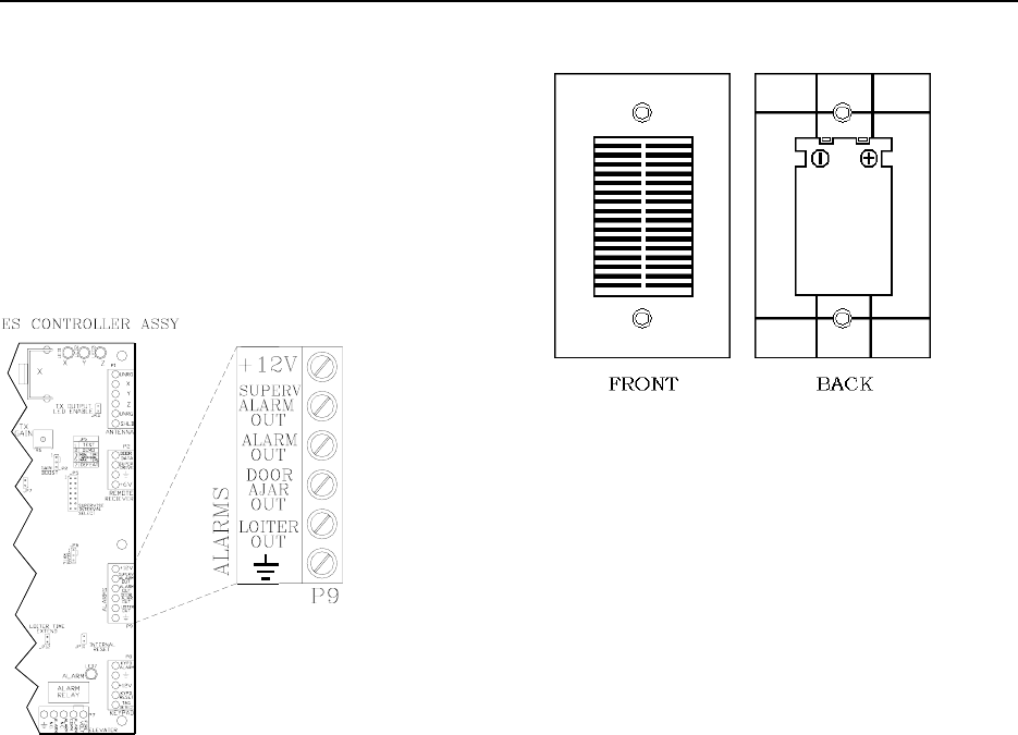
Figure 13.2 The Local Alarm
The Alarm Output Connector
The Alarm Output connector (Figure 13.1) is P9
on the Controller.
Pin 1 is +12V, Pin 2 is Supervisor Alarm out,
and so on.
Local Alarm Specifications
Power Requirements
Temperature
Weight
Power Requirements
12V DC
Temperature
Figure 13.1 The Alarm Output connector The Local Alarm operates best in an ambient
temperature between 35 and 90 degrees
Fahrenheit. Operation outside of this range may
cause unexpected or undesirable results,
including premature failure.
The Local Alarm
Local Alarm Specifications
Mounting the Local Alarm
Connecting the Local Alarm
Composite Cable
Weight
The Local Alarm (Figure 13.2; System Sensor
PA400 Series), a 90db at 10 feet piezo-signaling
device, is intended to attract attention near the
monitored zone only.
The Local Alarm weighs approximately 2.5
ounces.
Mounting the Local Alarm
Use a standard 2-1/2” deep single-gang box to
mount the Local Alarm with the two mounting
screws supplied.
Connecting the Local Alarm
You will need 22-gauge, 2-conductor plenum-
rated cable for installation.
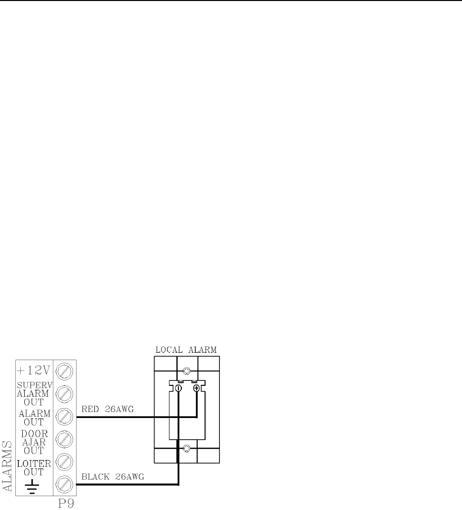
Installation Manual Alarm Output Devices 13-3
The Central Alarm
To connect the Local Alarm to the Controller,
refer to Figure 13.3 and use the following
instructions:
Central Alarm Specifications
Mounting the Central Alarm Unit
Connecting the Central Alarm
1. Using the RED wire, connect the
positive (+) terminal of the Local Alarm
to P9-pin3 (Alarm Out) of the
Controller.
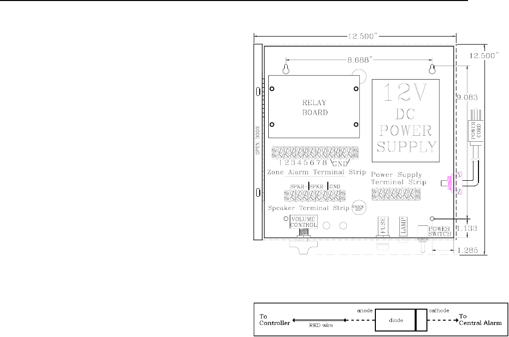
The Central Alarm (Figure 13.4) is located in its
own enclosure and contains its own Power
Supply, a Tone board, a Relay board and three
terminal strips.
2. Using the BLACK wire, connect the
negative (-) terminal of the Local Alarm
to P9-pin6 (Ground) of the Controller.
NOTE: If you are using composite
cable, the WHITE 22-gauge wire from
the composite, will connect to the RED
22-gauge wire from the Local Alarm
inside the junction box. The BLACK
wire from the Local Alarm can tie to the
common ground BLACK 22-gauge wire
from the composite.
One of the terminal strips is used for the factory
installed AC power cord. Another terminal strip
is used for connecting speakers to the central
alarm. A third terminal strip connects to the
various alarm tones offered by the tone board.
Central Alarm Specifications
Power Requirements
Temperature
Weight
Power Requirements
120V AC, 15 amp circuit from self-contained
Power Supply
Temperature
The Central Alarm operates best in an ambient
temperature between 35 and 90 degrees
Fahrenheit. Operation outside of this range may
cause unexpected or undesirable results,
including premature failure.
Weight
Figure 13.3 Connecting the Local Alarm
The Central Alarm weighs approximately 12
U.S. pounds.
Mounting the Central Alarm
Use hardware appropriate for the weight, size
and mounting surface.
13-4 Alarm Output Devices Installation Manual
Connecting the Central Alarm
You will need 22-gauge, 2-conductor plenum-
rate cable for installation.
The Alarm Output device from each Controller
can connect to any of the 8 alarm inputs at the
“Zone Alarm Terminal Strip” on the Central
Alarm.
In addition, a common ground from each
Controller connected to the Central Alarm is
required.
To connect the Central Alarm, refer to Figure
13.4 and use the following instructions: Figure 13.4 The Central Alarm
1. Using the BLACK wire, connect one of
the ground terminals on the Zone Alarm
Terminal Strip of the Central Alarm unit
to P9-pin6 (Ground) terminal of the
Controller you are connecting.
Figure 13.5 Diode orientation
About the Speakers
2. Using the RED wire, connect one of the
terminals on the Zone Alarm Terminal
Strip in the Central Alarm unit (with a
diode in-between the RED wire and Central
Alarm; Figure 13.5) to P9-pin3 (Alarm
Out) of the Controller you are
connecting.
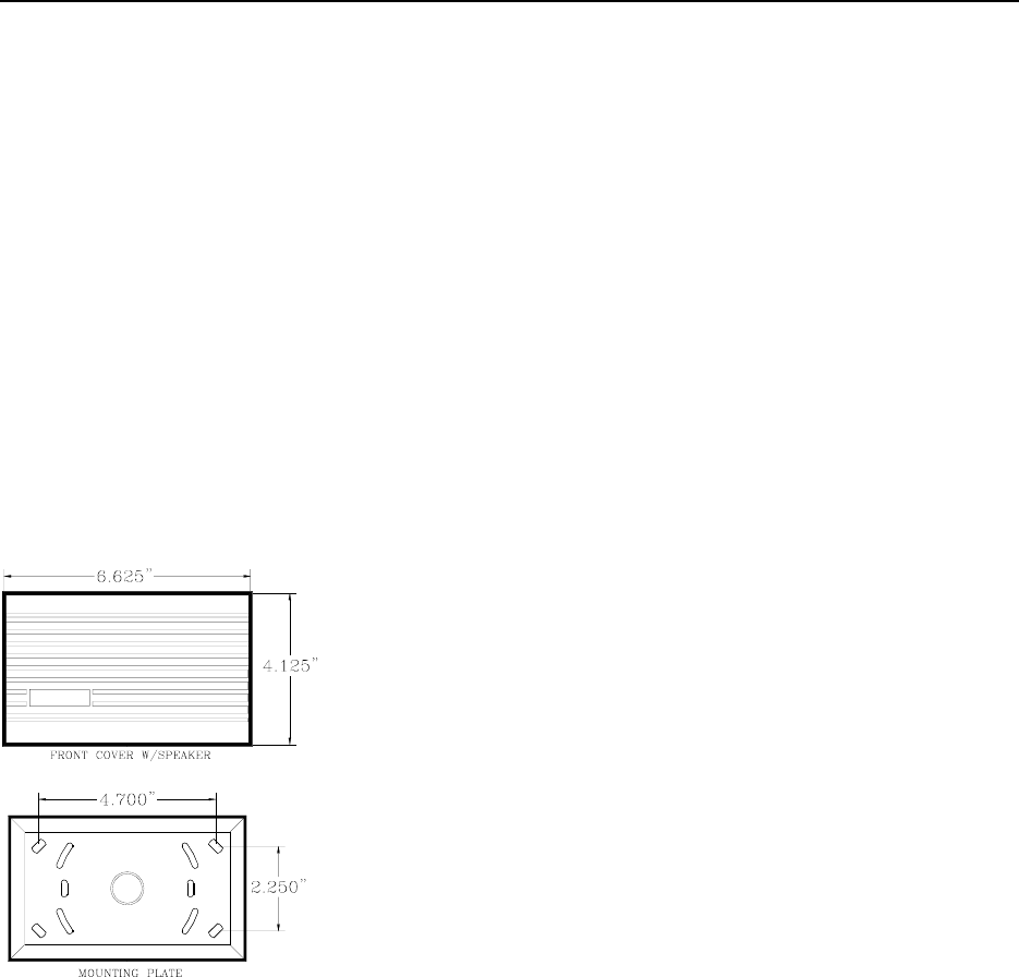
Speaker Specifications
Positioning the Speakers
Mounting the Speakers
Connecting Speakers to the Central Alarm
Speaker Volume Control
The Speakers (Figure 13.6) provided by Accutech
(Sentrol/Moose MPI Series) are 8-ohm speakers.
The tone board works with as little as 4 ohms.
NOTE: Sometimes a different tone is used for
each zone to distinguish one zone from another.
If you wish to use the same sound for one of
more zones, you will need to put a 1W diode
(1N400X ) in parallel with each signal that will
share a tone, and have their common cathodes
connect to the same terminal on the Zone Alarm
Terminal Strip.
When wiring the Speakers to the Central Alarm
unit, it is best to find a combination of series and
parallel connections that keep the total load of
the Speakers as close to 8 ohms as possible. You
may wish to consult with an Accutech technical
support person to verify your load.
Speaker Specifications
Power Requirements
Temperature
Weight
Installation Manual Alarm Output Devices 13-5
Power Requirements Mounting the Speakers
12V DC You will need 22-gauge, 2-conductor plenum-
rate cable for installation.
Temperature
To mount a Speaker(s), use the following
instructions:
Speakers operate best in an ambient temperature
between 35 and 90 degrees Fahrenheit.
Operation outside of this range may cause
unexpected or undesirable results, including
premature failure.
1. Using a small screwdriver, pry off the
bottom of the Speaker case.
2. Push out the knockouts for the mounting
holes.
Weight
3. Mark and drill the mounting holes.
Speakers weigh approximately 6 ounces.
4. Use appropriate hardware, secure the
Speaker to the mounting surface.
NOTE: The access slots in the Speaker
mounting plate should be large enough to
get the 2-conductor Speaker cable through
the opening. If it is not, drill the proper size
hole, or knock out the center knockout.
Connecting Speakers to the Controller
NOTES:
When using 3 Speakers, wire them in series.
When using 5 Speakers, wire them in parallel.
Up to 5 Speakers can be associated with one
Central Alarm unit.
Figure 13.6 The Speakers
Positioning the Speakers
To connect a Speaker to the Controller, use the
following instructions:
Speakers should be located where they can be
heard in several directions (such as hallway
intersections) to allow staff to hear alarms as
they occur. 1. Using RED wire, connect the positive
(+) of the Speaker to the positive (+) of
the Speaker Terminal Strip on the
Central Alarm.
13-6 Alarm Output Devices Installation Manual
2. Using BLACK wire, connect the
negative (-) of the Speaker to the
negative (-) of the Speaker Terminal
Strip on the Central Alarm.
Speaker Volume Control
To adjust Speaker volume, use the potentiometer
located on the bottom end of the Central Alarm .
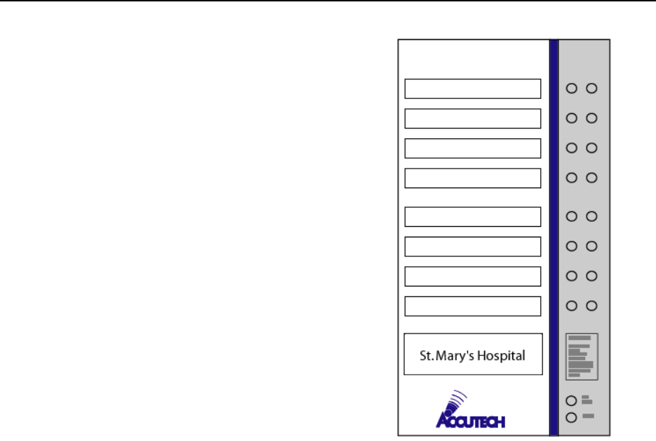
About the SAP
SAP Specifications
Mounting a SAP
Connecting a SAP to a Controller (up to 8)
A SAP (Figure 13.7), typically located at a staff
station, notifies staff when an alarm occurs in a
monitored zone through a piezo buzzer and
alarm-specific LEDs. The LEDs in the left
column will flash and the LEDs in the right
column will light steady.
Figure 13.7 A SAP example
SAP Specifications
As indicated on the SAP:
Power Requirements
Temperature
A Flashing Red LED means
an Alarm
Weight
Power Requirements
A Flashing Yellow LED means
a Check System
(System Supervisor alarm)
12V DC
Temperature
A Steady Red LED means
a Door Ajar alarm. A SAP operates best in an ambient temperature
between 35 and 90 degrees Fahrenheit.
Operation outside of this range may cause
unexpected or undesirable results, including
premature failure.
A Steady Yellow LED means
a Loiter alarm.
Weight
A SAP weighs approximately 1 pound.
Installation Manual Alarm Output Devices 13-7
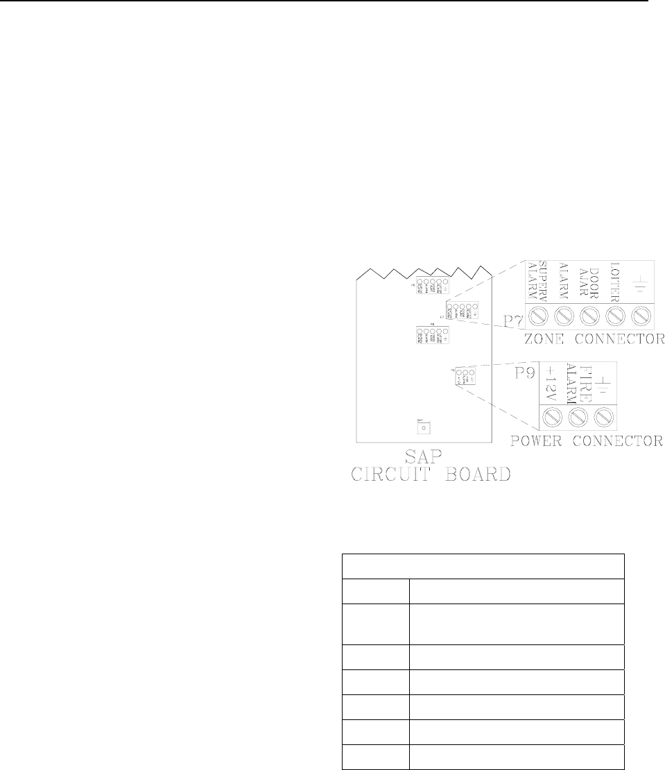
Mounting a SAP 3. A SAP only needs the use of 5 of these
wires for all but one zone. That zone
will be the one that provides power to
connector labeled P9 near the bottom of
the SAP circuit board.
To mount a SAP, use the following instructions:
1. Remove the front panel from its frame.
2. Using the SAP frame as a template,
mark the four mounting holes on the
mounting surface.
If you have locks or elevator deactivation, you
need to run a 2-conductor cable from the Fire
Panel Interface (FPI) for the fire alarm indicator.
3. Drill the mounting holes.
4. Secure the SAP frame to the mounting
surface using appropriate hardware and
replace the front panel.
Connecting a SAP to the Controller
NOTE:
On the 8-zone panel, P1 is for Zone 1, P2 is for
Zone 2 and so on.
Figure 13.8 Connecting a SAP to the Controller
To connect a SAP to the Controller, refer to
Figure 13.8 and use the following instructions:
Table 13.1 SAP Wire Color Code
Color Use for
RED +12v
(from one Controller only)
BLACK All Ground connections
BLUE All Supervise connections
WHITE All Alarm (Egress) connections
GREEN All Door Ajar connections
BROWN All Loiter connections
1. Run a separate 6-conductor unshielded
cable for each SAP that is connecting to
a Controller. The wire gauge will be
based upon the distance it will run (see
page 2-4).
2. For each zone, connect the appropriate
alarm outputs into their respective pins.
For consistency and ease of
troubleshooting use the color code
shown in Table 13.1.

13-8 Alarm Output Devices Installation Manual
The GDP GDP Specifications
GDP Specifications Power Requirements
Positioning and Mounting a GDP Temperature
Connecting an ESGDP
(ES 2200 systems only)
Weight
Connecting a GDP Power Requirements
BR Alarm filtered by HUB
12V DC
The GDP (Graphic Display Panel; Figure 13.9)
provides the staff with a visual representation of
the floor being monitored. GDPs are custom-
made to a facility’s floor plan and notify staff
when an alarm condition occurs in a monitored
zone through a piezo buzzer and alarm-specific
LEDs. Up to 16 Receivers (i.e., 16 zones) can be
linked to a single GDP.
Temperature
A GDP operates best in an ambient temperature
between 35 and 90 degrees Fahrenheit.
Operation outside of this range may cause
unexpected or undesirable results, including
premature failure.
Weight
NOTE: ES 2200 Systems use ESGDPs. To use a
GDP in an ES 2200 System you will need to
replace your ES 2200 Receivers. Contact your
Accutech Representative for more information.
Dependant on facility size and floor layout.
A typical GDP weighs approximately 2 pounds.
Positioning and Mounting a GDP
GDPs display these alarms (or events):
Position the GDP near a centralized staff
location.
Alarm (Egress)
Loiter
Door Ajar
Supervisor To mount a GDP, use the following instructions:
Fire Alarm
Band Removal (BR 4200 Systems only) 1. Open the front hinge panel.
2. Using the GDP frame as a template,
mark the mounting holes on the
mounting surface.
3. Drill the mounting holes.
4. Secure the GDP frame to the mounting
surface using appropriate hardware and
replace the front hinge panel.
Figure 13.9 A GDP example

Installation Manual Alarm Output Devices 13-9
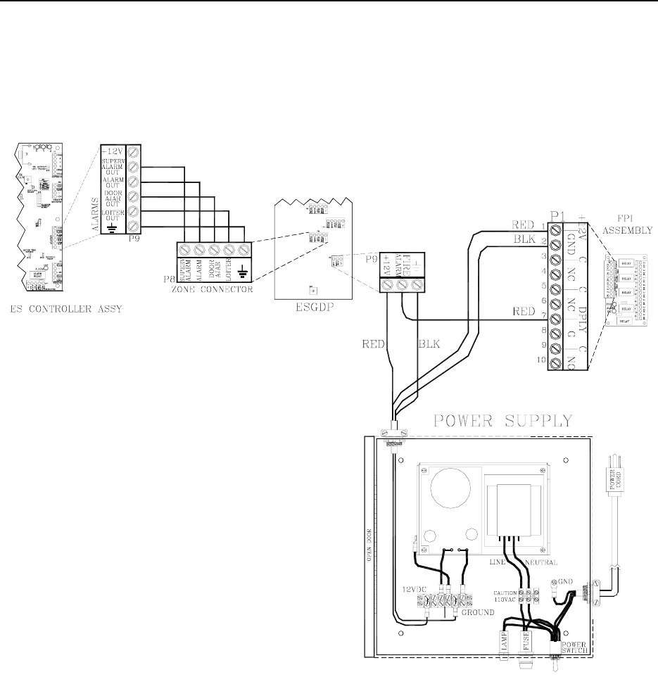
Connecting an ESGDP
(ES 2200 systems only)
To connect an ESGDP, refer to Figure 13.10 and
use the following instructions:
1. Connect the “+12V” and “Ground” from
the ESGDP to their respective pins on
the Power Supply.
2. For each Controller linked to the
ESGDP, connect all data pins of P9
(except +12V) to their respective pins
on a zone connector of the ESGDP.
NOTE: Up to 8 Receivers (i.e., 8 zones)
can be linked to a ESGDP.
3. Connect the “Fire” from the ESGDP to
the Fire Panel Interface (FPI) or the
facility Fire Panel.
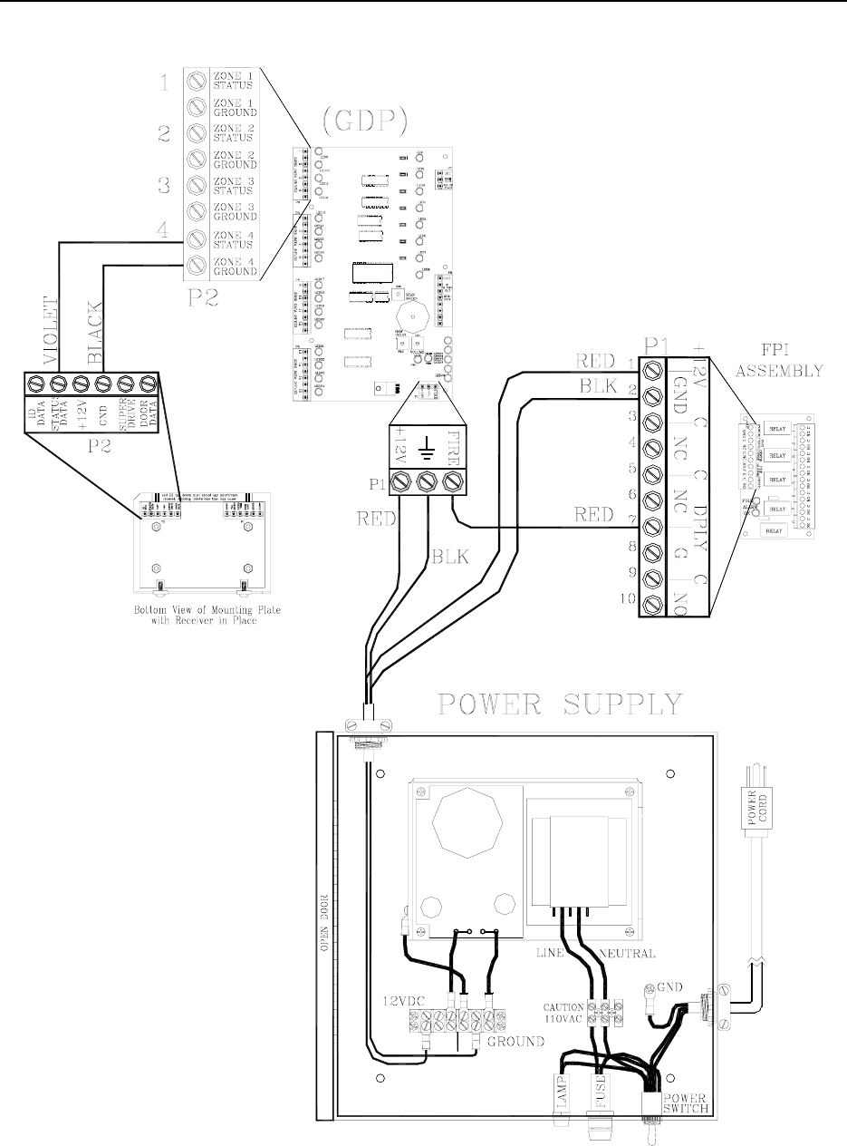
Connecting a GDP
NOTE: To use a GDP in an ES 2200 system,
you will need to replace your ES 2200
Receivers. Contact your Accutech
Representative for more information.
NOTE: Up to 16 Receivers (i.e., 16 zones) can
be linked to a single GDP board. Multiple GDP
boards can be housed within a GDP frame. If
more than one GDP board is present, perform all
steps on GDP board 1.
To connect a GDP, use the following
instructions.
Refer to Figure 13.11 for steps 1-3.
1. Connect the “+12V” and “Ground” from
the GDP to their respective pins on the
Power Supply.
2. For each Receiver linked to the GDP,
connect the “Status” and “GND” pins of
P2 to a zone data input of the GDP.
3. Connect the “Fire” from the GDP to the
Fire Panel Interface (FPI) or the facility
Fire Panel.
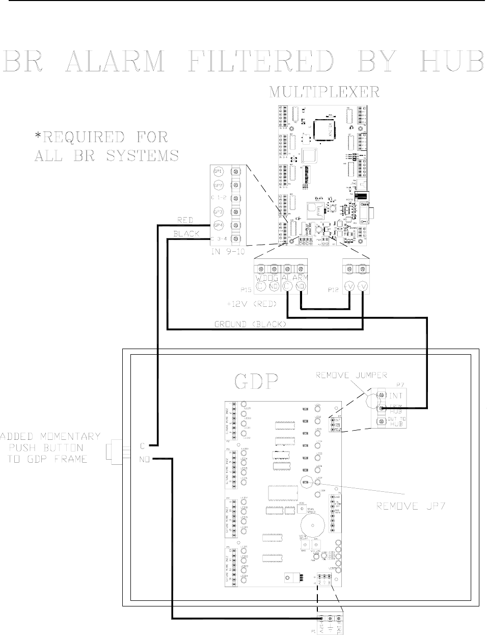
BR Alarm filtered by HUB
*Required for All BR Systems
Refer to Figure 13.12 for steps 4-10.
4. Remove jumper JP7 from the GDP.
5. Remove jumper between “INT” and
“FROM HUB” on P7 of the GDP.
6. Connect P15-4 (Alarm N.O.) to
P12-1 (+V) of the Multiplexer or
to 12V DC of the Power Supply.
7. Connect “IN-9-10”-Pin6 (C 3-4) to
P12-2 (-V) of the Multiplexer or
to GND of the Power Supply.
8. Connect the COM of the Momentary
Push Button to “IN 9-10”-Pin5 (GP4) of
the GDP.
9. Connect the N.O. of the Momentary
Push Button to P1 (+12V) of the GDP.
10. For connections to a Multiplexer, see
page 17-4.
13-10 Alarm Output Devices Installation Manual
Figure 13.10 Connecting an ESGDP (ES 2200 systems only)
Installation Manual Alarm Output Devices 13-11
Figure 13.11 Connecting a GDP – Graphic 1 of 2
13-12 Alarm Output Devices Installation Manual
Figure 13.12 Connecting a GDP – Graphic 2/2

Installation Manual
Chapter 14:
Elevator Deactivation

Installation Manual Elevator Deactivation 14-1
Elevator Deactivation
What to expect
Working with the Elevator Company
Elevator Deactivation Specifications
Positioning the Elevator Deactivation
Unit Weight and Dimensions
Mounting the Elevator Deactivation Unit
Wire and Cable
Wiring the Elevator Deactivation
Summary of Elevator Deactivation
for the Elevator Company
Elevator Deactivation prevents a Tag from using
an elevator.
There are two conditions where Elevator
Deactivation would be engaged.
The first condition is if the system detects a Tag
at a monitored elevator landing, the Elevator
Deactivation prevents the elevator from being
called to that floor by deactivating the elevator’s
call button at that floor.
The second condition is if the system detects a
Tag and the elevator is at the floor or en route,
the alarm will sound, the elevator doors will
remain open and the call button will be
deactivated.
What to expect
As soon as a Tag is detected, the elevator’s Call
Button for that floor/landing is deactivated. The
Call Button will remain deactivated for as long
as the Tag is in the Tx Activation Field, and for
an adjustable period of time (a delay) after the
Tag leaves.
If a delay is used with the Call Button, that delay
will “fool” the system into thinking a Tag is
present longer than it actually is. This means that
if the door is opened during this delay, the
system will go into alarm.
Once that time expires and there are no Tags in
the zone, the Call Button will resume operation.
Furthermore, if an elevator is already on its way
to that floor (because it was called before the
Tag entered the zone) the elevator will continue
to that floor. If the Tag leaves the Field before
the elevator doors open, the zone will not go into
alarm and the elevator will function as if the Tag
had never been there.
Finally, if the doors open while a Tag is present,
the system will go into “alarm” and the elevator
will be deactivated. This deactivation will take
place only for the elevator at that zone. The
alarm is “latched”, meaning that it will not
automatically reset itself once the Tag has left
the area. A Keypad reset is required to reset the
zone and reactivate the elevator.
Working with the Elevator Company
It will be necessary to work with the facility’s
elevator company in order to connect the
Elevator Deactivation Circuitry. The Accutech
system contains most of the circuitry needed to
deactivate the elevators; however, the elevator
company will need to be provided with relays.
The Elevator Deactivation cabinet is used for
this purpose.
Elevator Deactivation Specifications
Power Requirements
Temperature
Weight
Power Requirements
12V DC
Temperature
The Elevator Deactivation unit operates best in
an ambient temperature between 35 and 90
14-2 Elevator Deactivation Installation Manual
Mounting the Elevator Deactivation
cabinet
degrees Fahrenheit. Operation outside of this
range may cause unexpected or undesirable
results, including premature failure.
To mount the Elevator Deactivation cabinet, use
the following instructions:
Weight
1. Choose your location and appropriate
mounting hardware.
The Elevator Deactivation cabinet weighs 3.5
U.S. pounds.
Positioning the Elevator Deactivation 2. Open the Elevator Deactivation cabinet
and locate the four mounting holes.
The cabinet containing the relays for the
Elevator Deactivation Circuitry (Figure 14.1)
should be located in the room containing the
elevator controls.
3. Mark-out and drill four holes
corresponding to the holes in the back of
the cabinet.
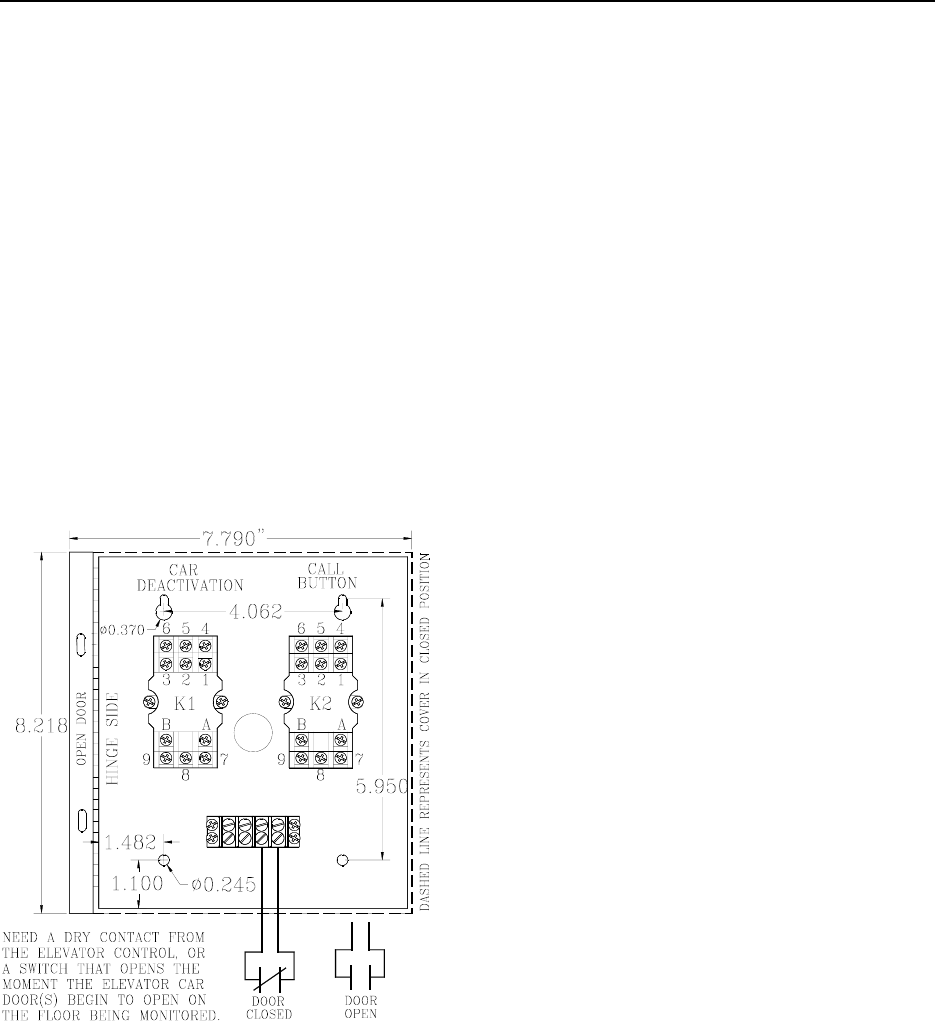
Figure 14.1 The Elevator Deactivation unit
4. Push out one of the knock-outs in the
cabinet for wire/conduit access.
5. Connect conduit or strain relief fittings.
6. Position the cabinet over the holes you
drilled and secure the cabinet to the
mounting surface.
NOTES:
The first condition is the presence of a Tag at a
monitored zone. The second condition, in the
case of elevator deactivation, is an indication of
an open door at a monitored zone.
If a door position switch, typically dry contacts
from the elevator control or some form of
magnetic switch, is not available, then a Passive
Infrared Reader (PIR) is focused near the
monitored opening. (see Chapter 10)
Wire and Cable
We recommend using an 18-gauge,
6-conductor cable for hookup between the relay
cabinet and the Controller.

Installation Manual Elevator Deactivation 14-3
Local or State Code may require the wire to be
run in conduit. Be sure to check your
requirements before beginning work.
NOTE: State codes require that all lock and
elevator deactivation circuitry be wired into the
facility’s fire alarm system. This is done so that
in case of fire, any lock or elevator deactivation
unit disengages, allowing for free egress or
ingress. Be sure to check your local codes and
see Chapter 12 on Fire Panel Interface Units.
Wiring the
Elevator Deactivation Circuitry
For wiring the Elevator Deactivation use 18
AWG (CL2-P), 6-conductor non-shielded
Plenum cable.
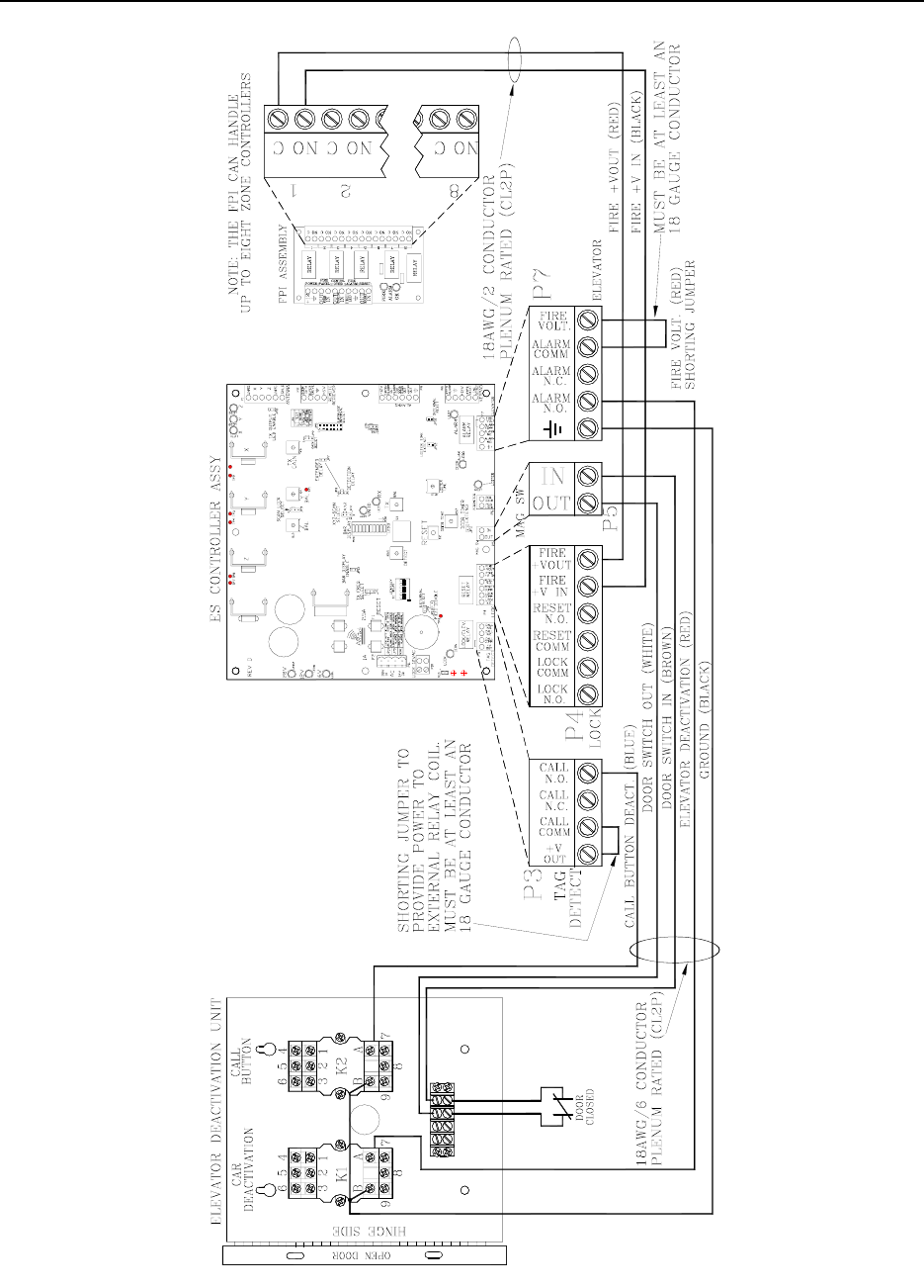
To wire the Elevator Deactivation, refer to
Figure 14.1 & 14.2 and use the following
instructions:
1. Using the RED wire, connect K1 (Car
Deactivation) Relay terminal marked
“A” (coil +) to P7-pin2 (the “Alarm
N.O.” terminal) of the Controller.
2. Using the BLUE wire, connect K2 (Call
Button Deactivation) Relay screw
terminal marked “A” (coil +) to P3-pin4
(the “Call N.O.” terminal) of the
Controller.
3. Using BLACK wire, place a jumper
wire between the “B” terminals (Coil-)
of the K1 and K2 Relays.
4. Using the BLACK wire, connect the
screw terminal marked “B” of one of the
Relays to P7-pin1 (the GROUND
terminal) of the Controller.
5. Using the BROWN wire, connect the
right most screw terminal of the 4
position terminal strip located in the
bottom of the cabinet to P5-pin2 (the
“IN” terminal) of the Controller.
6. Using the WHITE wire, connect the
second from the right screw terminal of
the 4 position terminal strip to P5-pin1
(the “Out” terminal) of the Controller.
NOTE: These two terminals in steps 5 &
6 will be used for hookup of the N.C.
dry contact of the second condition
source.
7. At the P3 connector add an 18-gauge
jumper wire from the “Call Comm”
terminal (pin 2) to “+ Volt Out” (pin 1).
8. At the P7 connector add an 18-gauge
jumper wire from the “Fire Volt”
terminal to the “Alarm Comm” terminal.
9. At P4 pins 5 & 6, connect the fire panel
interface contacts (See Chapter 12).

14-4 Elevator Deactivation Installation Manual
At the Second Condition Source:
If the second condition source is provided by the
elevator controls, Use the previously wired
terminals on the 4- position screw terminal strip
in the Elevator Deactivation Relay cabinet to
hookup to the dry contract.
If the second condition source is a locally
mounted Magnetic Switch or a Passive Infrared
Reader (PIR) unit, wire them to the Controller.
Summary of Elevator Deactivation
for the Elevator Company
Call Button Deactivation
Elevator Car Deactivation
The following is a brief summary of Elevator
Deactivation that can be given to the Elevator
Company.
Call Button Deactivation
When a Tag is detected in the monitored
Elevator zone, the Accutech system energizes
Relay K2 and the Call Button for that Elevator
zone is deactivated.
When the K2 Relay is de-energized, the Call
Button is reactivated.
Elevator Car Deactivation
When a Tag is detected in the monitored
Elevator zone and the second condition is met,
the Accutech System energizes Relay K1.
If the elevator car is at the floor (with doors
open) the elevator will be deactivated.
If the elevator car is on its way to that floor, it
will continue to that floor and upon arrival (with
doors open) will be deactivated.
As long as relay K1 is energized, the elevator
doors will remain open preventing the car from
leaving the floor.
When Relays K1 is de-energized, the Elevator
will return to normal operation.
Installation Manual Elevator Deactivation 14-5
Figure 14.2 Connecting the Elevator Deactivation unit to the Controller

Installation Manual
Chapter 15:
Perimeter Functions
Installation Manual Perimeter Functions 15-1
Perimeter Functions
Perimeter Lock
Perimeter Door Ajar (Timer Override)
The Timer
Perimeter System
Perimeter functions allow the user to monitor
and/or lock a door on a timed schedule.
Perimeter Lock
A typical application might be a door that has
high traffic during the day but almost no traffic
at night. During the day it may make sense to
allow the free ingress or egress of staff and
visitors, but at night, locking the door will mean
added security for staff and residents.
Using a Timer, the door could be locked at the
desired time and unlocked at the desired time.
During this locked time, the door would function
normally. Entering a valid code into a Keypad or
activating a PBO would be required to open the
door. If a Delayed Egress Lock were used, those
functions would operate as they normally do.
Perimeter Door Ajar (Timer Override)
A typical example for a Perimeter Door Ajar
would be a door that has high traffic during the
day, but has very little traffic at night. If
someone were to “prop” the door open, for any
reason, and then forget about it, the potential for
a Tag egress would exist.
For example, during the day there could be a 90-
second delay with the Door Ajar alarm;
however, during the evening with the Perimeter
Door Ajar function activated, the door would
alarm the moment it was opened. The Perimeter
Door Ajar function supercedes the normal Door
Ajar timer setting.
As always, entering a valid code into a Keypad
or activating a PBO would allow free egress
through the door.
The Timer
Timer Specifications
Positioning and Mounting the Timer
Connecting the Timer
Programming the Timer
NOTE: This section only covers functions of the
Timer that apply to the Accutech System; for
complete information consult the Timer’s
manual.
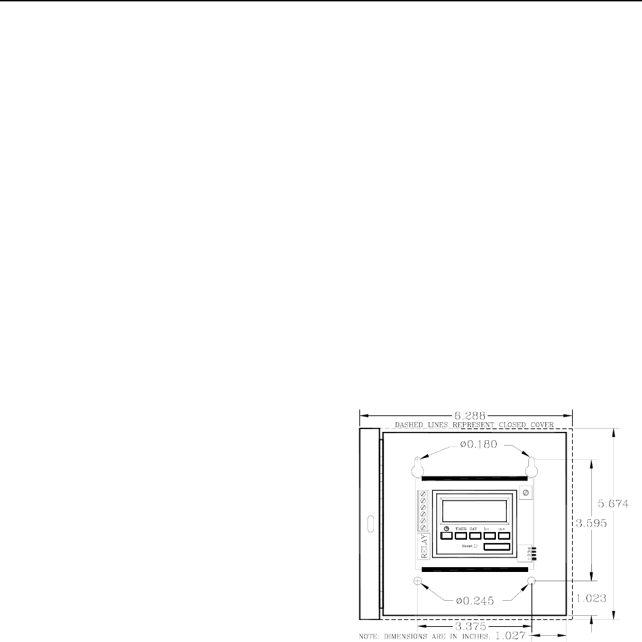
The Timer Accutech provides (Figure 15.1) uses
military time units and can be set for daily,
weekly or block period events.
Figure 15.1 The Timer
Timer Specifications
Power Requirements
Temperature
Weight
Power Requirements
12V DC
15-2 Perimeter Functions Installation Manual
Temperature
The Timer operates best in an ambient
temperature between 35 and 90 degrees
Fahrenheit. Operation outside of this range may
cause unexpected or undesirable results,
including premature failure.
Weight
The Timer (including cabinet) weighs 2 U.S.
pounds.
Positioning and Mounting the Timer
It is best to position the Timer near the
Controller that it will interface with. Use
hardware appropriate for the weight, size and
mounting surface when mounting the Timer.
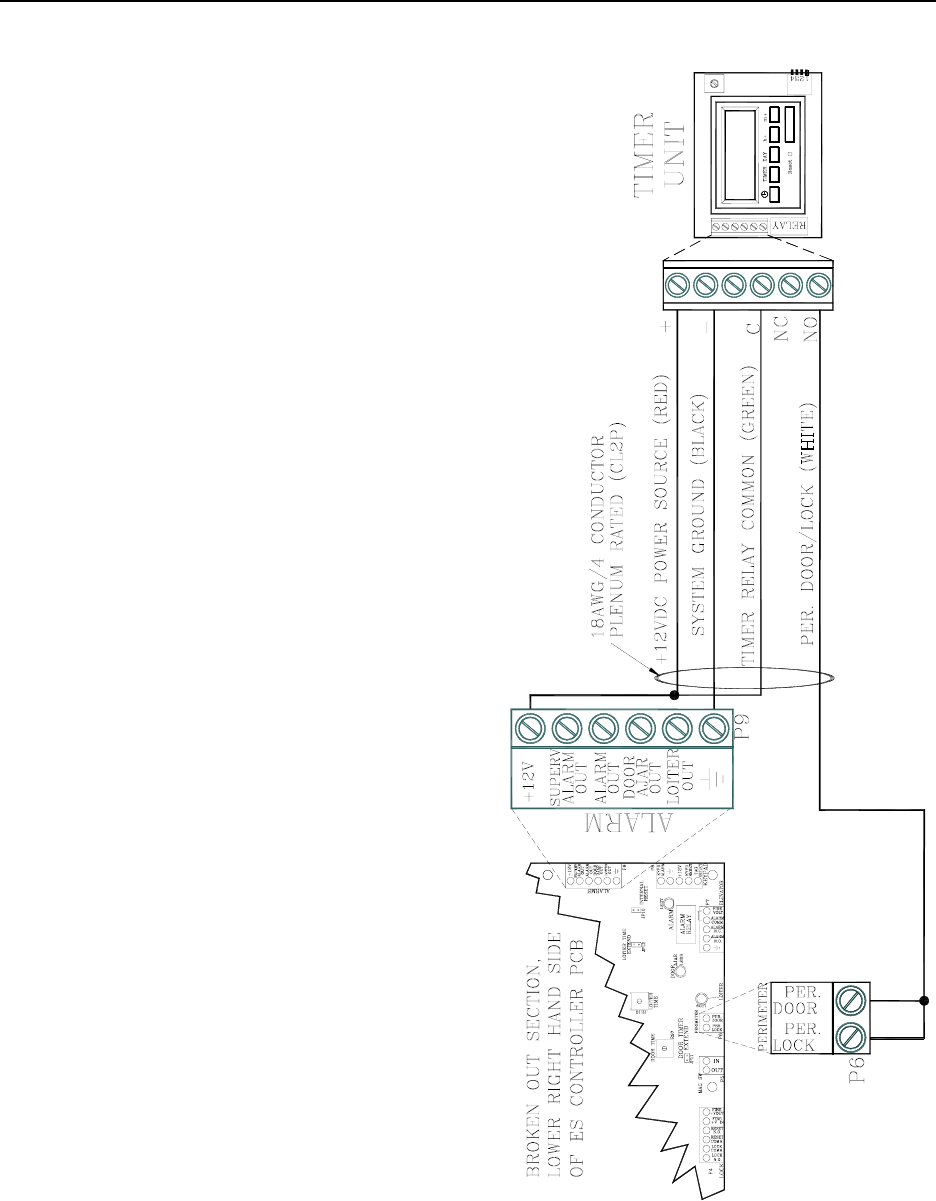
Connecting the Timer
You will need 18-gauge, 4-conductor Plenum-
rated cable for installation.
To connect the Timer to the Controller, refer to
Figure 15.2 and use the following instructions:
1. Using the BLACK wire, connect the “-“
pin of the Timer to P9-pin6 (Ground) of
the Controller.
2. Using the RED wire, connect the “+”
pin of the Timer to P9-pin1 (+12V) of
the Controller.
3. Using the WHITE wire, connect the
“N.O” pin of the Timer to both P6 pins
of the Controller.
4. Using the GREEN wire, connect the
“C” pin of the Timer to P9-pin1 (+12V)
of the Controller.
Figure 15.2 Connecting the Timer

Installation Manual Perimeter Functions 15-3
Programming the Timer
Setting the Time
Programming for a Day and Time
Programming for all Week
Setting ON/OFF times
Programming the Timer requires you to set
event times and whether to turn the system on or
off at those times.
Setting the Time
To set the Timer time, refer to Figure 15.1 and
use the following instructions:
1. Activate the Memory Backup Battery by
switching mode set dipswitch 1 to ON.
NOTE: The LCD will come on flashing
displaying: Off 00:00
2. Apply system power to the FT-100 unit.
3. Press and hold the “clock” button.
4. To set hours, use the button marked
“h+”.
5. To set minutes, use the button marked
“m+”.
6. To set day of the week, use the button
marked “Day”.
7. Release the “clock” button.
Programming for a Day and Timer
To program an ON or OFF instruction for a
particular day and time, refer to Figure 15.1 and
use the following instructions:
1. Select the desired timer (1 thru 6 ON; 1
thru 6 OFF) using the “Timer” button.
2. Program the desired time and day using
the “h+”, “m+” and “Day” buttons.
3. Press and release the “clock” button to
exit the program mode.
NOTE: If a Day is not selected, the action will
occur every day.
Programming for all week
To program an ON or OFF instruction for all
week, refer to Figure 15.1 and use the following
instructions:
1. Select the desired timer (1 thru 6 ON; 1
thru 6 OFF) using the “Timer” button.
2. Program the desired time using the “h+”
and “m+” buttons.
3. Press and release the “clock” button to
exit the program mode.

15-4 Perimeter Functions Installation Manual
Setting ON/OFF times
To set ON/OFF times for predetermined timer
events, refer to Figure 15.1 and use the
following instructions:
1. To enter the program mode, press and
release the button marked “Timer” once.
NOTE: The LCD will show:
Timer 1 ON --:--
2. Pressing the “Timer” button a second
time will set the unit to OFF timer 1.
NOTE: This sequence will continue for
6 ON timers and 6 OFF timers for a total
of 12 timers.
3. Press and release the “clock” button to
exit the program mode.
Perimeter System
You can also monitor a perimeter door without
the use of a Timer. The door would remain
locked at all times and would require a valid
code entered into a Keypad (to exit) or
activating a PBO (to enter).
To set the Accutech System for this situation, on
the Controller, jumper P8-pin 3 (+12V) to P6-
pin 1 (Per Lock).

Installation Manual
Chapter 16:
Automatic Door Deactivation

Installation Manual Automatic Door Deactivation 16-1
Automatic Door Deactivation
In automatic door applications (doors that open
via a motion sensor or push paddle), the
Accutech System can deactivate this feature
when a Tag enters monitored zone’s Tx
Activation Field.
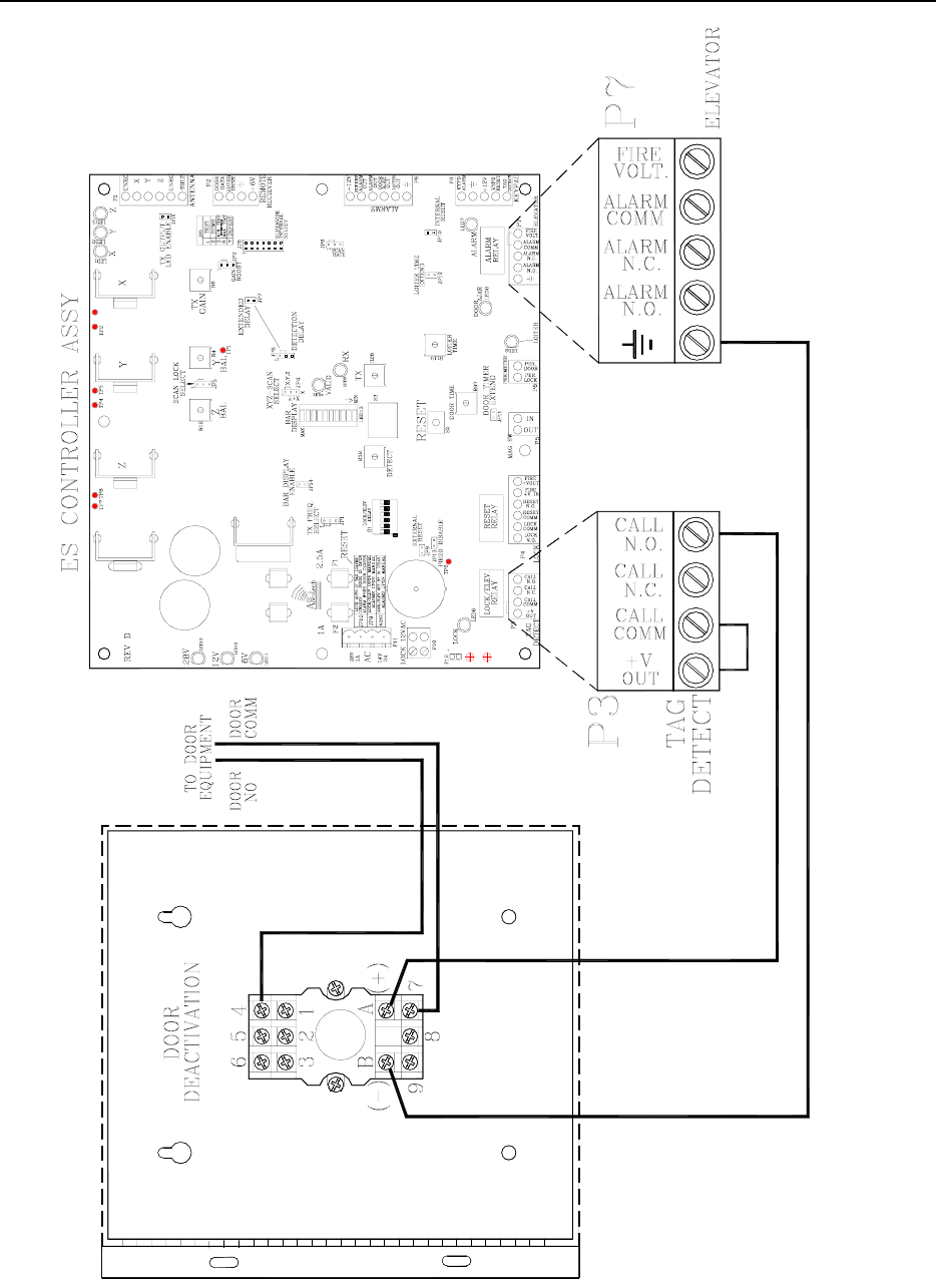
Wiring Automatic Door Deactivation
To wire the Controller for Automatic Door
Deactivation, refer to Figure 16.1 and use the
following instructions:
1. On the Controller, jumper pins 1
(+V Out) and 2 (Call Comm) of P3.
2. Connect pin 1 (Call N.O) of P3 to the
positive (+) of the 12V DC Relay.
3. Connect pin 5 (Ground) of P7 to the
negative (-) of the 12V DC Relay.
4. Connect 4 (N.O.) and 7 (Comm) to the
door equipment.
16-2 Automatic Door Deactivation Installation Manual
Figure 16.1 Wiring for Automatic Door Deactivation

Installation Manual
Chapter 17:
The Multiplexer

Installation Manual the Multiplexer 17-1
The Multiplexer
Multiplexer Specifications
Mounting the Multiplexer
Positioning the Multiplexer
Multiplexer jumpers
Wiring the Multiplexer
Multiplexer board settings
The Multiplexer (Figure 17.1), used only in IS
3200 and BR 4200 Systems, decodes and relays
information from up to 8 Receivers to GDPs and
PCs with the Accutech Software.
The Multiplexer comes inside a Controller case;
this case can accommodate up to 2 Multiplexer
boards (16 Receivers).
Multiplexer Specifications
Power Requirements
Temperature
Weight
Power Requirements
12V DC from Power Supply
Temperature
A Multiplexer operates best in an ambient
temperature between 35 and 90 degrees
Fahrenheit. Operation outside of this range may
cause unexpected or undesirable results,
including premature failure.
Weight
The Multiplexer (with the Controller enclosure
and the maximum 2 Multiplexer contained
within) weighs approximately 10 U.S. pounds.
Positioning the Multiplexer
The Multiplexer can be located above the drop
ceiling or remotely in a utility closet. However,
since Accutech Systems use RS232 cable to
connect from the Multiplexer to the PC (at a 19/2
baud rate), 50 feet is the recommended maximum
distance from the PC to Multiplexer Board 1
with out any special cabling or converters.
Consult your Accutech Representative for
special cases.
Mounting the Multiplexer
Multiplexers (up to 2) are housed in a Controller
enclosure. Use hardware appropriate for the
weight, size, and mounting surface. See Chapter
3 for case mounting instructions.
17-2 the Multiplexer Installation Manual
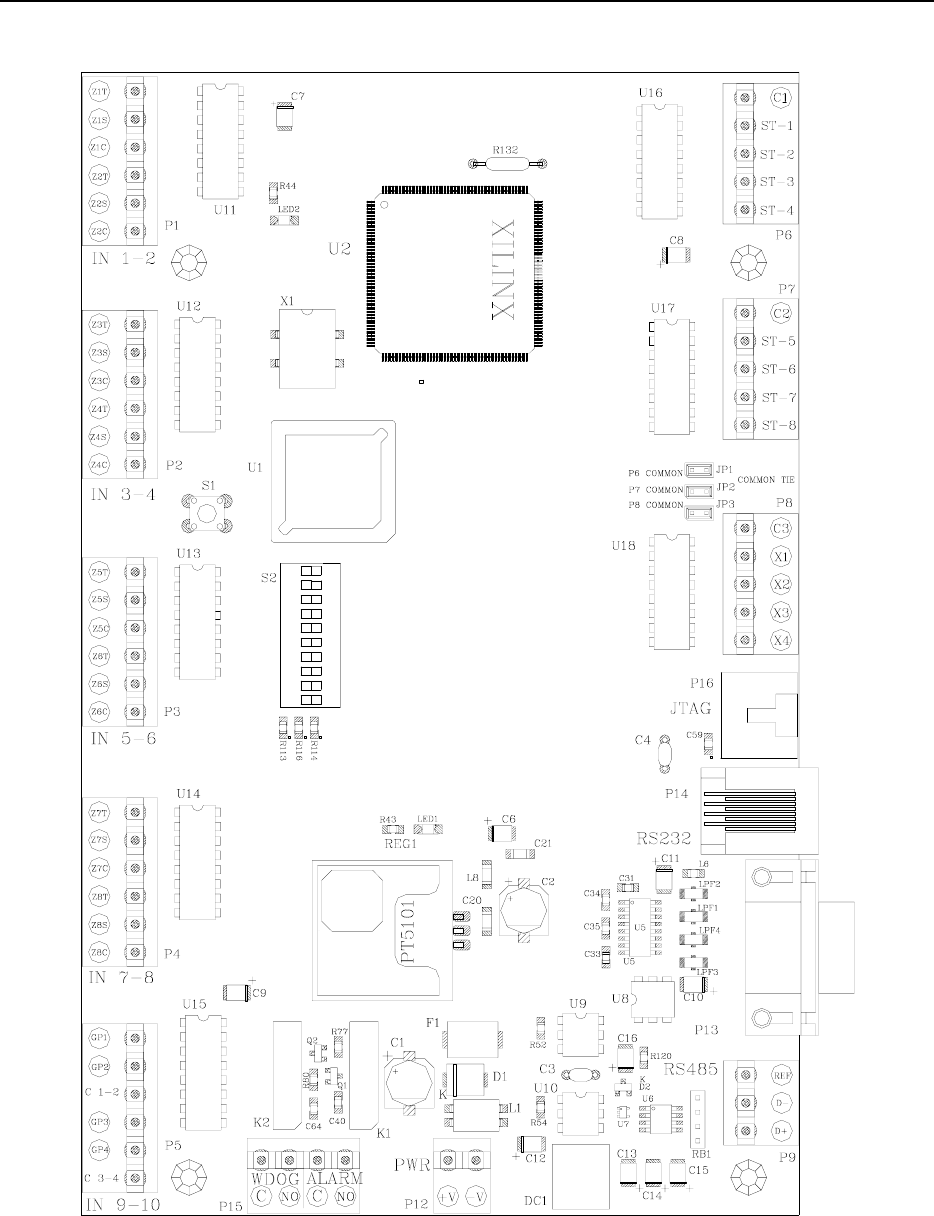
Figure 17.1 The Multiplexer PCB

Installation Manual the Multiplexer 17-3
Multiplexer Jumpers
The three Multiplexer jumpers, JP1-3 (Figure
17.1), should remain in place for the unit to
function properly.
Wiring the Multiplexer
To the Power Supply
From Receivers
To GDP
To PC
To other Multiplexers
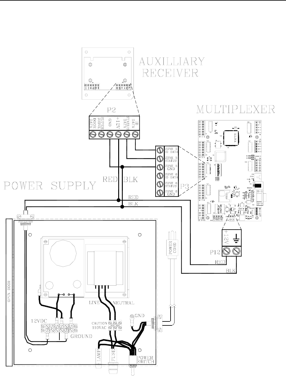
To the Power Supply
Using RED and BLACK wire, connect the +12V
and Ground between the Power Supply terminal
strip and the Multiplexer (P12 pins 1 and 2).
From Receivers
NOTE: When connecting Receivers to the
Multiplexer, their input positions on the
Multiplexer are determined by (and must
match) the software configuration (see the
example configuration on page 19-2).
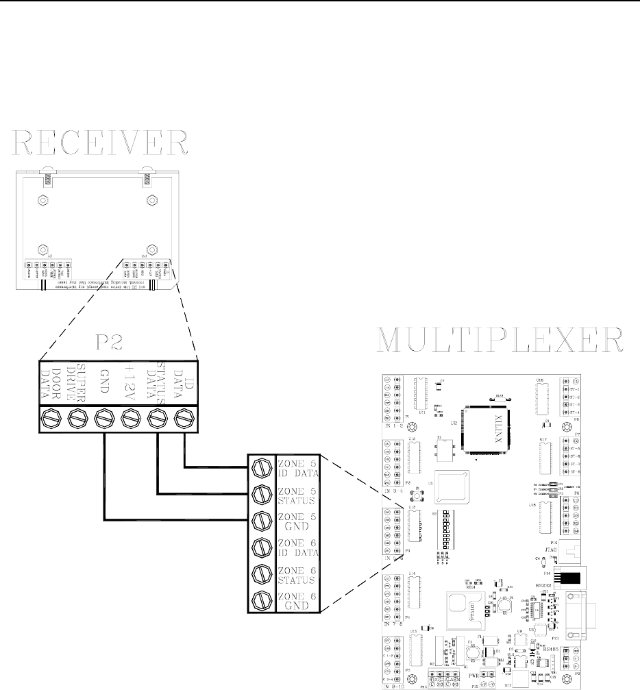
To connect a Receiver to a Multiplexer, refer to
Figure 17.2 – 17.3 and use the following
instructions:
1. Up to 8 Receivers can be connected to
one Multiplexer. Connecting a Receiver
to a Multiplexer requires 3 wires.
2. For each Receiver, connect pins 1, 2 and
4 (ID Data, Status Data, and Gnd) to one
input zone (Z1T, Z1S and Z1C) on the
Multiplexer.
NOTE: Do not tie Grounds together
unless they have the same source.
For example, the first Receiver (e.g.,
Zone 1) will connect to Z1T, Z1S, and
Z1C; the second Receiver (e.g., Zone 2)
will connect to Z2T, Z2S and Z2C, and
so on.
NOTE: Only use IN 1-2, IN 3-4, IN 5-6
and IN 7-8 for inputs; do not use IN 9-
10.
17-4 the Multiplexer Installation Manual
Figure 17.2 Connecting a Receiver to a Multiplexer
Installation Manual the Multiplexer 17-5
Figure 17.3 Connecting an Auxiliary Receiver