Innovative Control Systems IGWT-662008 S-TAD User Manual Install Manual v2 36 ES IS BR July 2007
Innovative Control Systems Inc S-TAD Install Manual v2 36 ES IS BR July 2007
Contents
- 1. User Manual 1 of 4
- 2. User Manual 2 of 4
- 3. User Manual 3 of 4
- 4. User Manual 4 of 4
User Manual 3 of 4
17-6 the Multiplexer Installation Manual
To GDP
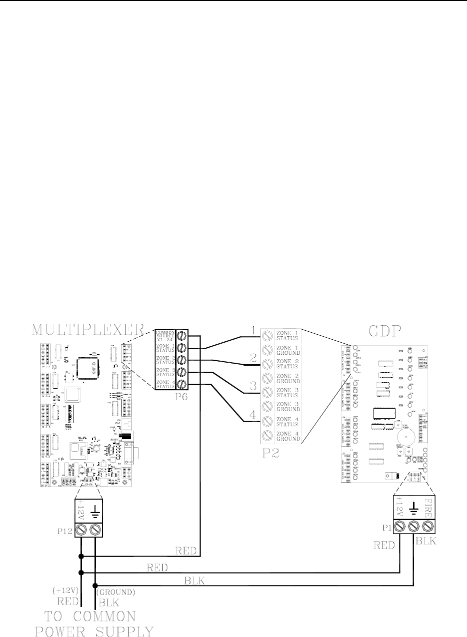
To connect a Multiplexer to a GDP, refer to Figure
17.4 and use the following instructions:
1. On the Multiplexer, jumper P12-pin 1
(+12V) to P6-pin 1 (C1) to provide power
to that output.
2. Connect P6-pin2 (ST-1) of the Multiplexer
to P2-pin 1 (1) of the GDP. The GDP will
now receive and display data from Zone 1.
For additional GDPs, connect the ST-(#)
outputs of the Multiplexer to the (#) inputs
of the GDPs. For example ST-1 to 1 will be
Zone 1, ST-2 to 2 will be Zone 2, and so
on.
Figure 17.4 Connecting a Multiplexer to a GDP(s)
Installation Manual the Multiplexer 17-7
To PC
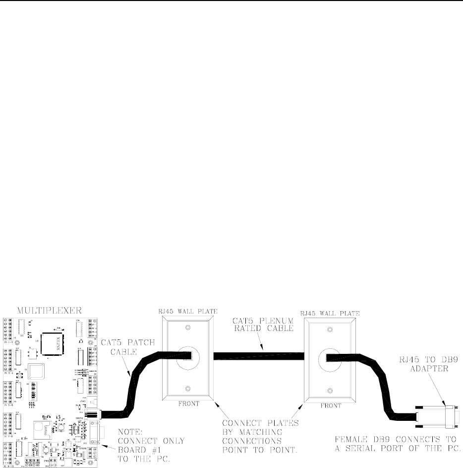
To connect a Multiplexer to a PC, refer to Figure
17.5 -17.6 and use the following instructions:
1. Using CAT5 and a DB9 connector, connect
the Multiplexer to a serial port of the PC
(serial port #1 recommended).
NOTE: Depending on the distance between
the Multiplexer and the PC, you may want
to use RJ45 wall plates for simplicity.
Figure 17.5 Connecting a Multiplexer to a PC
17-8 the Multiplexer Installation Manual
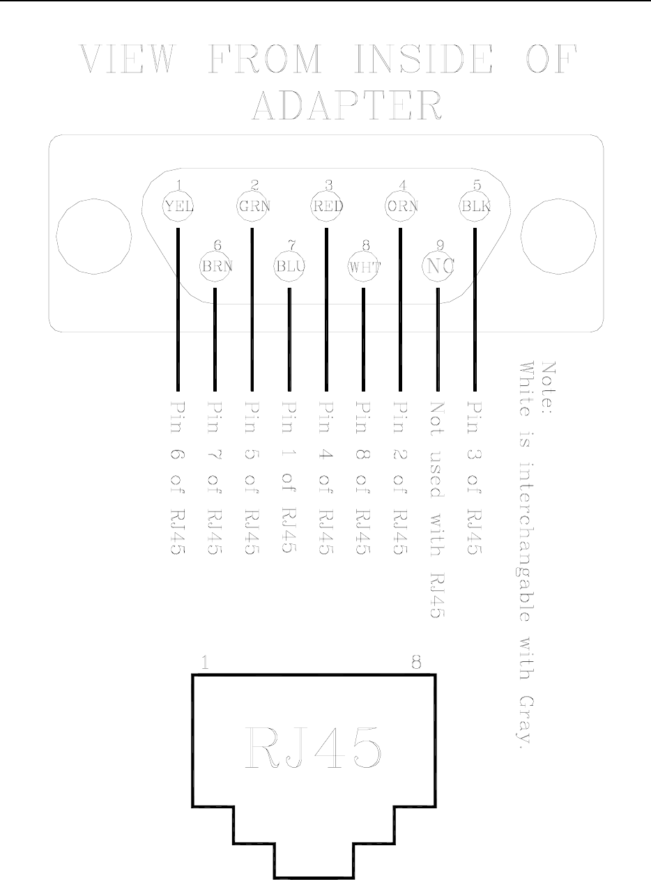
Figure 17.6 DB9 to RJ45 connector
Installation Manual the Multiplexer 17-9
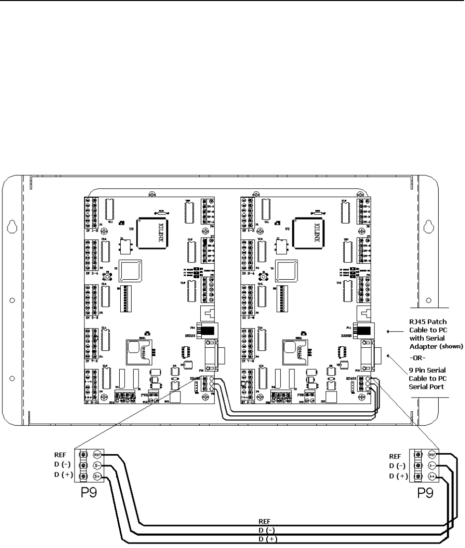
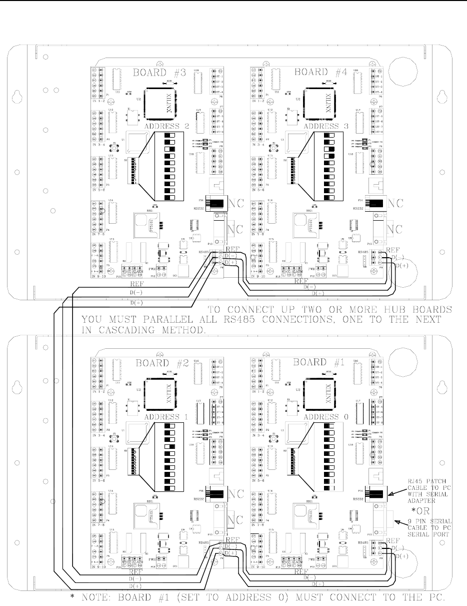
To other Multiplexers
To connect two more or Multiplexers, parallel all
RS485 connections, one to the next in cascading
method. (see Figures 17.7 and 17.8).
Figure 17.7 Connecting Multiplexers within a case
17-10 the Multiplexer Installation Manual
Figure 17.8 Connecting Multiplexer cases
Installation Manual the Multiplexer 17-11
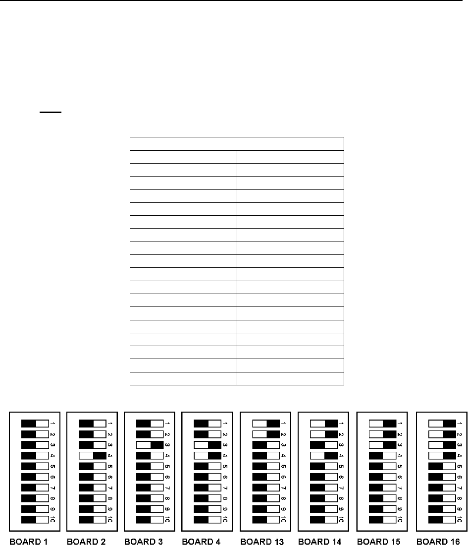
Multiplexer board settings
Use the board settings below (Table 17.1 and Figure 17.9)
for Dip Switch S2 on the Multiplexer.
NOTE: Only board 1 (Address 0000) should be plugged
into the PC.
Table 17.1 Multiplexer Board Settings
Board Number Dip Switch Setting
1234
1 0000
2 0001
3 0010
4 0011
5 0100
6 0101
7 0110
8 0111
9 1000
10 1001
11 1010
12 1011
13 1100
14 1101
15 1110
16 1111
Figure 17.9 Multiplexer Switch Settings

Installation Manual
Chapter 18:
Power Supply

Installation Manual Power Supply 18-1
Power Supply
Power Supply Specifications
Positioning the Power Supply
Mounting the Power Supply
Connecting the Power Supply
Some installations of the Accutech System
peripherals require more power than the
Controller can provide. In these cases, a Power
Supply (Figure 18-1) is added to the system to
meet the additional power requirements.
Power Supply Specifications
Power
Temperature
Weight
Power
120V AC, 2 amp
Temperature
A Power Supply operates best in an ambient
temperature between 35 and 90 degrees
Fahrenheit. Operation outside of this range may
cause unexpected or undesirable results,
including premature failure.
Weight
A Power Supply weighs approximately 12
pounds.
Positioning the Power Supply
The Power Supply is located above the drop
ceiling or remotely in a utility closet near a
120V AC dedicated power outlet.
Mounting the Power Supply
Use appropriate hardware for the weight and
mounting surface.
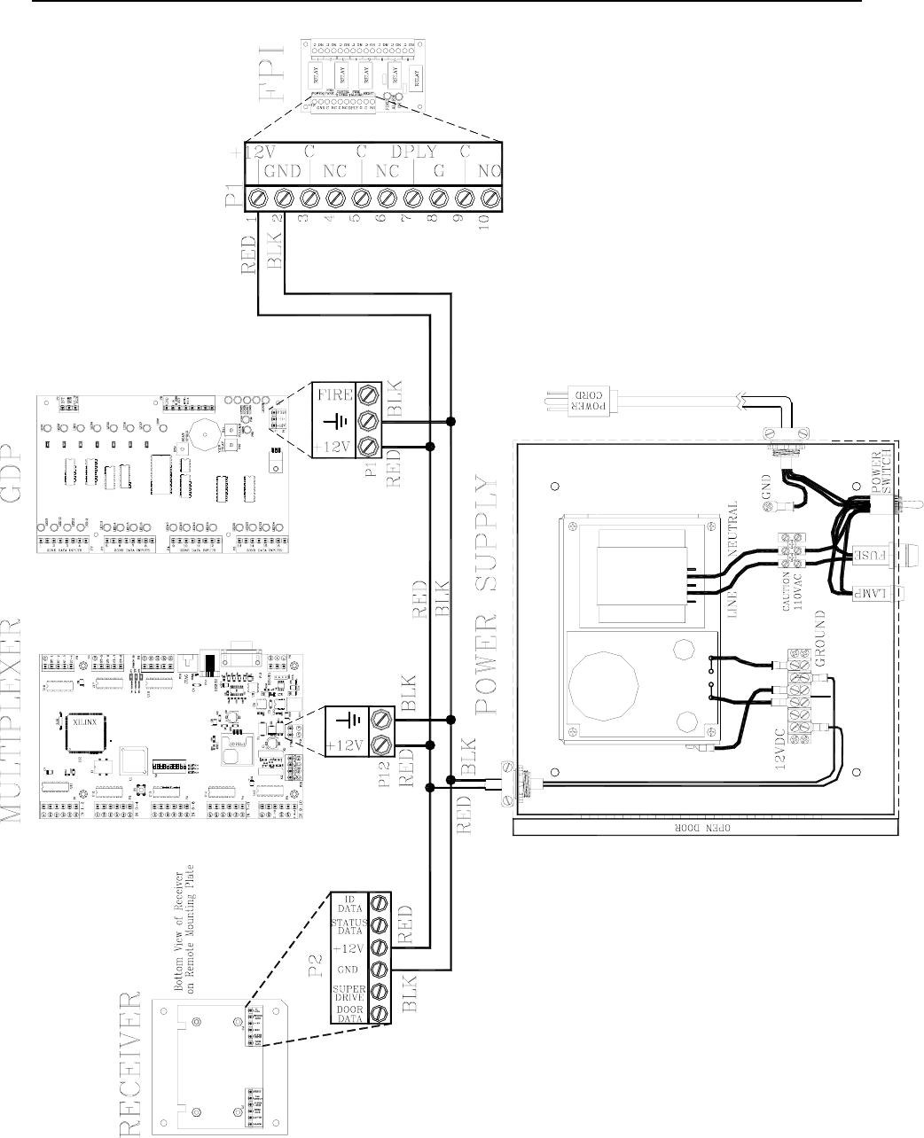
Connecting a Power Supply
For all connections to the Power Supply, use 18-
gauge, 2-conductor wire. To connect a Power
Supply, refer to Figure 18.1 and the respective
component:
To a GDP
To a FPI
To a BR 4200 Receiver
To a Multiplexer
To a GDP
Using RED and BLACK wire, connect the +12V
and Ground between the Power Supply terminal
strip and GDP.
To a FPI
Using RED and BLACK wire, connect the +12V
and Ground between the Power Supply terminal
strip and FPI.
To a BR 4200 Receiver
NOTE: Connections between the BR 4200
Receiver(s) and Multiplexer should be
completed first (see pages 17-3 - 17-5).
Using RED and BLACK wire, connect the
+12V and Ground between the Power Supply
terminal strip and FPI.
To a Multiplexer
NOTE: Connections between the Multiplexer
and BR 4200 Receiver(s) should be completed
first (see pages 17-3 and 17-5).
Using RED and BLACK wire, connect the +12V
and Ground between the Power Supply terminal
strip and Multiplexer.
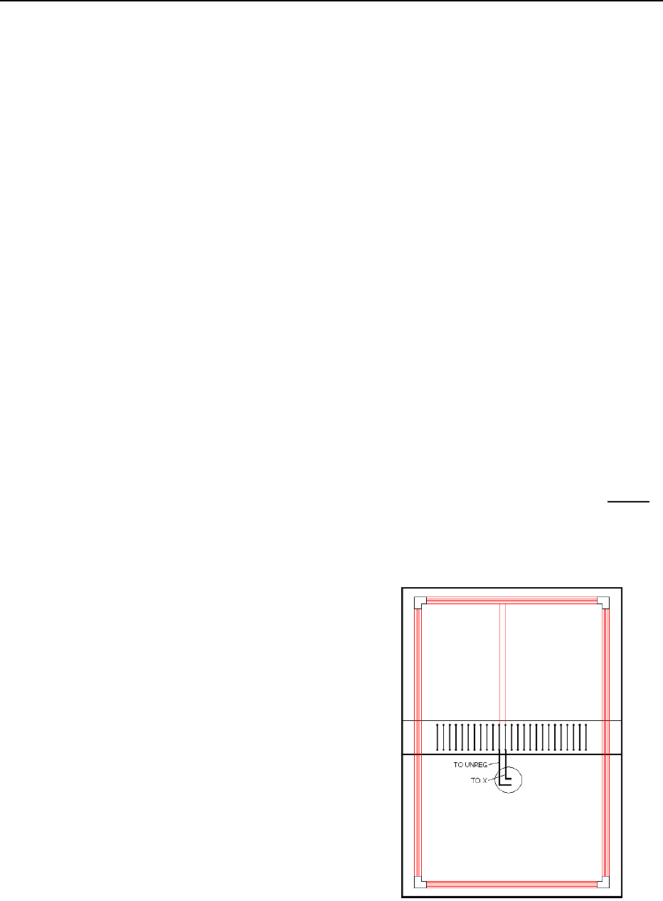
18-2 Power Supply Installation Manual
Figure 18.1 Power Supply connections

Installation Manual
Chapter 19:
The Accutech Software

Installation Manual the Accutech Software 19-1
The Accutech Software
Minimum System Requirements
Recommended System Components
Installing the Accutech Software
Uninstalling the Accutech Software
Example System Configuration
The Accutech Software (v4.10 or greater)
displays incoming event information via the
Multiplexer from monitored zones. The PC
screen will display events in real-time using the
facility’s floor plan as the background.
The Accutech Software is separate from and
does not affect or control the physical Accutech
security system.
Minimum System Requirements
Intel Celeron 400mHz
17” Monitor (capable of displaying
1024x768 pixels in 16-bit high color
8.4 GB Hard Drive
64MB PC-100 SDRAM
8MB AGP Video Card
Sound Card
Speakers
3 ½ “ Floppy Drive
24x CD-ROM Drive (minimum available)
Motherboard w/Intel BX or VIA 133
Chipset (should be expandable, i.e., 3 PCI,
1 ISA, 1 ASP. 2 Serial, 2 USB, 1 parallel
Keyboard
Mouse
Mouse Pad
Windows NT, Me, 2000 or XP
If this is a Networked System, you will
need a Network Interface Card (NIC).
Accutech recommends a 3Com PCI NIC.
1 Serial 9pin COM PORT
Recommended System Components
Pentium 4 Processor 1.8 GHz
128 MB PC-133 SDRAM
16 MB Video Card
16-bit PCI Sound Card
Windows 2000
Windows Service Pack 2 or higher
Installing the Software
NOTE: Windows 2000 users will need
Administrator privileges to install the software.
1. Close all other applications before
installing the Accutech Software.
2. Place the Accutech CD in your
CD-ROM drive.
3. If Autoplay is enabled, the installation
program will begin.
4. If Autoplay is not enabled:
a. From the Start menu, Settings,
select Control Panel.
b. Double-click “Add/Remove
Programs”.
c. Click “Add New Programs”.
NOTE: Windows Me users,
click “Install”.
d. Click “CD or Floppy”.
e. Click “Next”.
f. Click “Finish”.
5. In the Accutech installer, follow the on-
screen instructions to accept all default
settings.
6. When prompted, reboot your computer
to complete installation.
19-2 the Accutech Software Installation Manual
Uninstalling the Accutech Software
1. From the Start menu, Programs,
Accutech, select “Remove Accutech
Patient Security System”.
A confirmation message box appears.
2. Click “Yes”.
3. Click “Close” to exit the uninstaller
program.
4. From the Start menu, Programs,
Accessories, select “Windows
Explorer”.
5. Select the ICS folder (C:\ics) and delete
it.
6. Reboot the PC.
Example System Configuration
A facility’s system configuration will depend on
its particular needs.
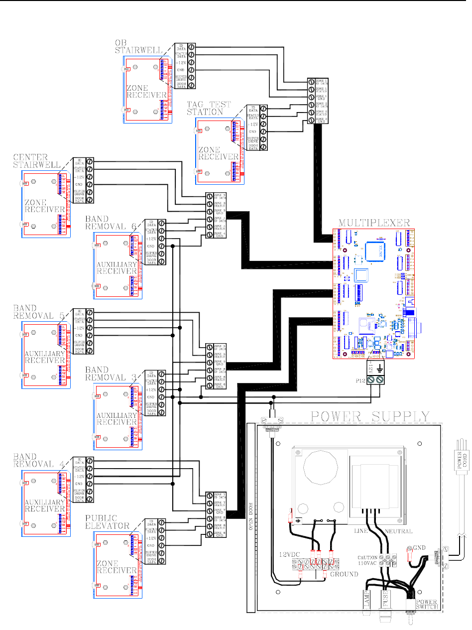
However, as an example, Figures 19.1 and 19.2
show an 8-zone BR 4200 System Hospital with
software configuration.
NOTE: When connecting Receivers to the
Multiplexer, their input positions on the
Multiplexer are determined by (and must
match) the software configuration.
Example Hospital
floor example
zone 1 sardoorst “OB Stairwell” 868 525
reader 2 sanurse “Tag Test Station” 790 425
zone 3 saddoor “Center Stairwell” 638 312
zone 4 sabr “Band Removal 6” 880 388
zone 5 sabr “Band Removal 5” 631 499
zone 6 sabr “Band Removal 3 Nursery” 380 410
zone 7 sabr “Band Removal 4” 540 390
zone 8 saelevator “Public Elevator” 608 263
title “Example Hospital” 2200 2200
Figure 19.1 Example Software configuration
Installation Manual the Accutech Software 19-3
Figure 19.2 Example Software configuration - connections

Installation Manual
Chapter 20:
Tag Test Station
Installation Manual Tag Test Station 20-1
Tag Test Station Positioning and Mounting a TTS
TTS Specifications Tag Test Stations are typically located at staff
stations near a computer with the Accutech
Software and are secured by four mounting
screws.
Positioning and Mounting a TTS
Connecting a TTS
The Tag Test Station (TTS) is used for Tag
assignments. In a similar fashion to a Tx wand
antenna, the TTS emits a small Tx Activation
Field that activates Tags. Once activated a Tag
sends a signal to the Receiver. The Receiver
sends this information to the Multiplexer, which
sends it to the computer with the Accutech
Software. The Tag Reader Status dialog box
appears on the PC screen where it can be
assigned or unassigned.
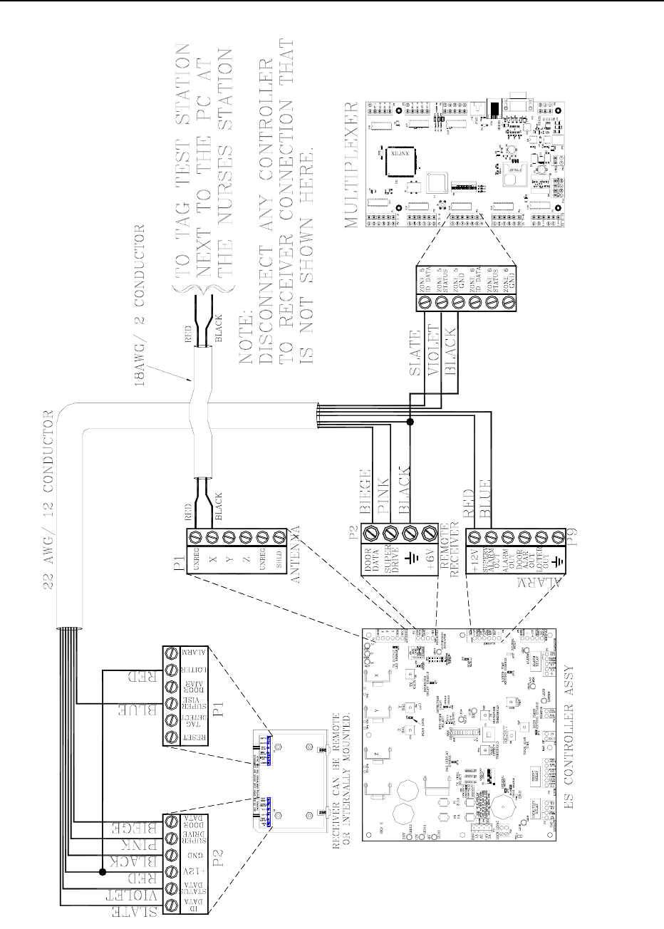
Connecting a TTS
To connect a TTS, refer to Figures 20.1 - 20.3
and use the following instructions:
1. Connect P1-pin1 (“UNREG”) from the
Controller to the connector strip of the
TTS.
2. Connect P1-pin2 (“X”) from the
Controller to the connector strip of the
TTS.
TTS Specifications
Power Requirements
Temperature
Weight
3. Note that TTS zones are for Tag
assignment purposes only; you do not
wire the other positions of the Receiver
to the Controller. Disconnect any signal
not shown (see Figure 20.2).
Power Requirements
Dependant upon Controller.
Temperature
A TTS operates best in an ambient temperature
between 35 and 90 degrees Fahrenheit.
Operation outside of this range may cause
unexpected or undesirable results, including
premature failure.
Weight
A TTS weighs approximately 10 ounces.
Figure 20.1 Inside a TTS
20-2 Tag Test Station Installation Manual
Figure 20.2 Connecting a TTS – Part 1/2
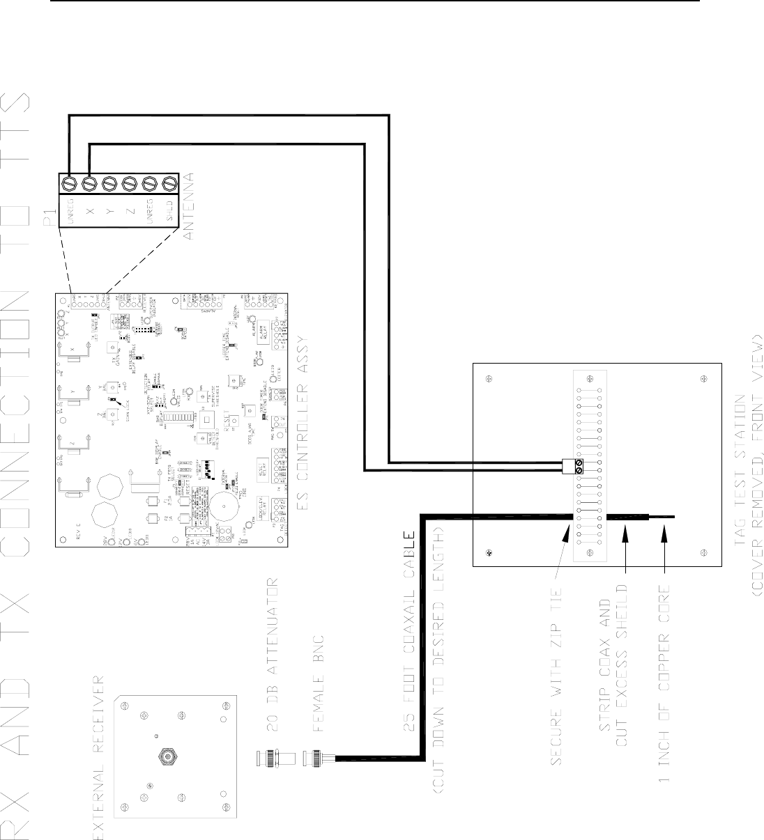
Installation Manual Tag Test Station 20-3
Figure 20.3 Connecting a TTS – Part 2/2

Installation Manual
Chapter 21:
Band Removal Lockdown

Installation Manual Band Removal Lockdown 21-1
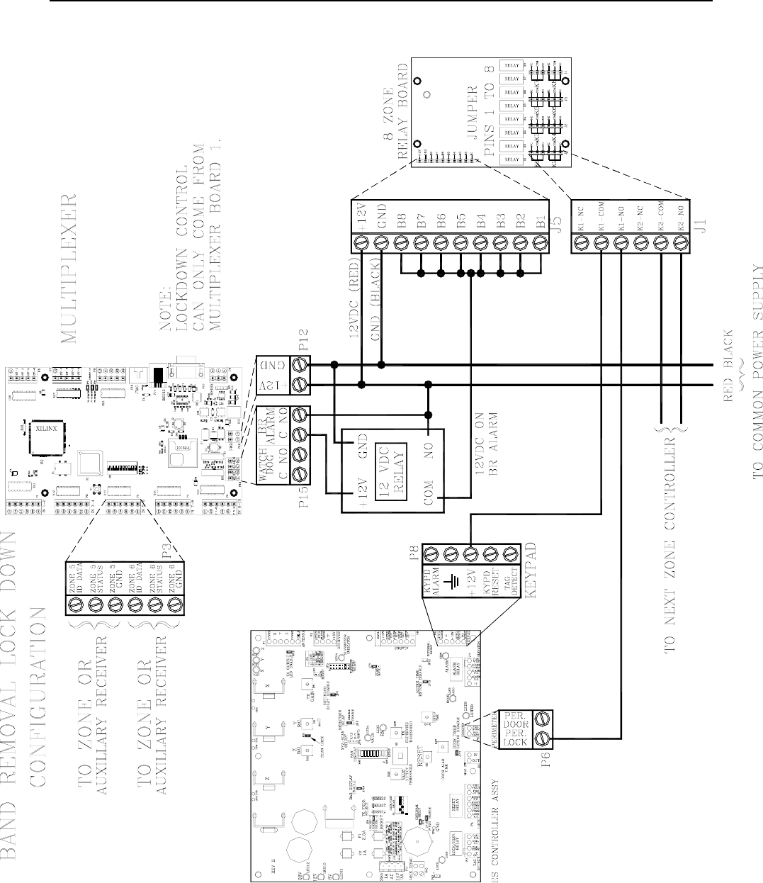
Band Removal Lockdown
Band Removal Lockdown engages all facility
Magnetic Locks when a Band Removal alarm
occurs.
The Multiplexer controls a 12V DC signal that
can be sent to the Relay board. The Relay
controls a 12V DC signal from each Controller
to the Lock(s) at each zone.
When a Band Removal alarm occurs, the
Multiplexer sends 12V DC to the Relay Board.
The Relay Board then sends 12V DC to P6-pin 1
(Per Lock) of each Controller (up to 8)
connected to it. This engages the Magnetic
Locks at all zones equipped with Locks. A
Keypad Reset at any zone is required to end the
lockdown.
For Multiplexers that are connected in series,
use Board 1 only to provide a dry contact
(P15 - C./N.O.) that closes upon a Band
Removal alarm.
Please use an external 12V DC relay between 8-
zone relay board and Multiplexer BR alarm
relay (P15).
Wiring Band Removal Lockdown
To wire the Controller for Band Removal
Lockdown, refer to Figure 21.1 and use the
following instructions:
1. For these connections, use Multiplexer
Board 1 only.
2. Connect P15-3 ( C ) on the Multiplexer
to +12v on the external 12V DC relay.
3. Connect +12V DC of Power Supply to:
a. P12-1 (+12v) position of
Multiplexer
b. P15-4 (N.O.) position of the
Multiplexer
c. +12V position of 8-zone relay
board (J5)
d. (N.O.) position of external
12V DC relay
4. Connect GND of Power Supply to:
a. P12-2 (GND) position of
Multiplexer
b. GND position of 8-zone relay
board (J5)
c. GND position of external
12V DC relay
5. Tie pins B1 through B8 to one common
point together on the 8-zone Relay
Board and connect that common point to
the external 12V DC relay at COM
position.

21-2 Band Removal Lockdown Installation Manual
6. For each Controller (Lock) you must
pick a set of contacts to work with on
the Relay Board. The example in Figure
21.1 shows Relay K1 being used:
a. Connect P8-3 (+12V) on the
Controller to J1 at (K1-Com) on
the 8-zone Relay Board.
b. Connect P6-1 (Per. Lock) on the
Controller to J1 at (K1-NO) on
the 8-zone Relay Board.
7. Do the same for contact K2 through K8.
8. If more than 8 zones are being locked,
then additional Relay boards will need
to be connected.
a. Connect +12V and GND of the
each Relay Board in parallel to
+12V and GND of the first
Relay Board.
b. Tie pins B1 through B8 of each
Relay Board to one common
point together on that Relay
Board and connect the common
point of each Relay Board to the
external 12V DC relay at COM
position.
9. Repeat step 7 for each Controller (Lock)
choosing a different set of contacts (K1-
K8) of the Relay Board for each zone to
be locked down when a Band Removal
alarm occurs.
Installation Manual Band Removal Lockdown 21-3
Figure 21.1 Wiring Band Removal Lockdown

Installation Manual
Chapter 22:
User-Defined Settings
Installation Manual User-Defined Settings 22-1
User-Defined Settings
Door Ajar
Door Ajar Reset
Loiter
Loiter Reset
System Supervise
Power Loss Supervise
NOTE: The following settings are up to the
facility’s discretion. All times are approximate.
Door Ajar
A Door Ajar alarm occurs when a door is open
for longer than the preset time. By setting a
delay using R97 and JP11, you can adjust the
time (from 10 to 110 seconds) necessary before
a Door Ajar alarm occurs preventing nuisance
Door Ajar alarms from air flow or slight bumps
to the door.
R97 (Door Ajar Delay)
Factory Set to 15 seconds
Set mid scale or as desired to delay onset of
Door Ajar alarm.
JP11 (Door Timer Extend Disable)
Factory Default IN
This jumper determines the timing range of the
Door Ajar Time potentiometer (R97).
Table 22.1 JP11
Position Time Range
In 10-60 seconds
Out 65-110 seconds
Door Ajar Reset
JP16 determines if the Door Ajar automatically
resets once the door is fully closed.
Table 22.2 JP16
Position Door Ajar Automatically Resets?
In Yes
Out No
Loiter
A Loiter alarm occurs when a Tag lingers in the
Tx Activation Field for longer than the preset
allotted time. By setting a delay using R110 and
JP12, you can adjust the time necessary (from 10
to 110 seconds) before a Loiter alarm occurs
preventing nuisance Loiter alarms from normal
resident movement or passersby.
R110 (Loiter Delay)
Factory Set to 15 seconds
Set mid scale or as desired to delay onset of
Loiter alarm.
JP12 (Loiter Time Extend Disable)
Factory Default IN
This jumper determines the timing range of the
Loiter Timer potentiometer (R110)
Table 22.3 JP12
Position Time Range
In 10-60 seconds
Out 65-110 seconds
22-2 User-Defined Settings Installation Manual
Loiter Reset
JP10 determines if the Loiter alarm
automatically resets once the Tag leaves the
zone.
Table 22.4 JP10
Position Alarm Automatically Resets?
In Yes
Out No
System Supervise
JP5 determines how often the System Supervisor
checks the Accutech System. For more
information about the System Supervisor, see
page 3-6.
Table 22.5 JP5 Positions and Results
Position Result
(Check system Once/Time Interval)
1 Test
(testing purposes only)
2 Demo; Once/min
(demonstration purposes only)
3 Once/ 2 Hours
4 Once/ 4 Hours
5 Once/ 8 Hours
6 Once/16 Hours
7 Disable
Power Loss Supervise
The Controller has a Power Loss Supervise
function that will indicate that the system power
has been lost. For complete information about
this function, see page 3-7.

Installation Manual
Appendix A:
Discontinued Components
Installation Manual Appendix A: Discontinued Components A-1
Appendix A:
Discontinued Components
From time to time, system components may
become discontinued due to revisions,
improvements, or unavailability from the
manufacturer.
ES 2100 Receiver
Composite Cable (Part #200355)
Tag styles (gray and yellow colored)
ES 2100 Receiver
Receiver Specifications
Internal vs. External Receivers
Receiver Mounting Options
Receiver Positioning/Stagger Tuning
Connecting the Receiver
Adjusting the Receiver
NOTE: The ES 2100 Receiver is a special
order item only; it is no longer in production
and is replaced with an IS 3200 Receiver.
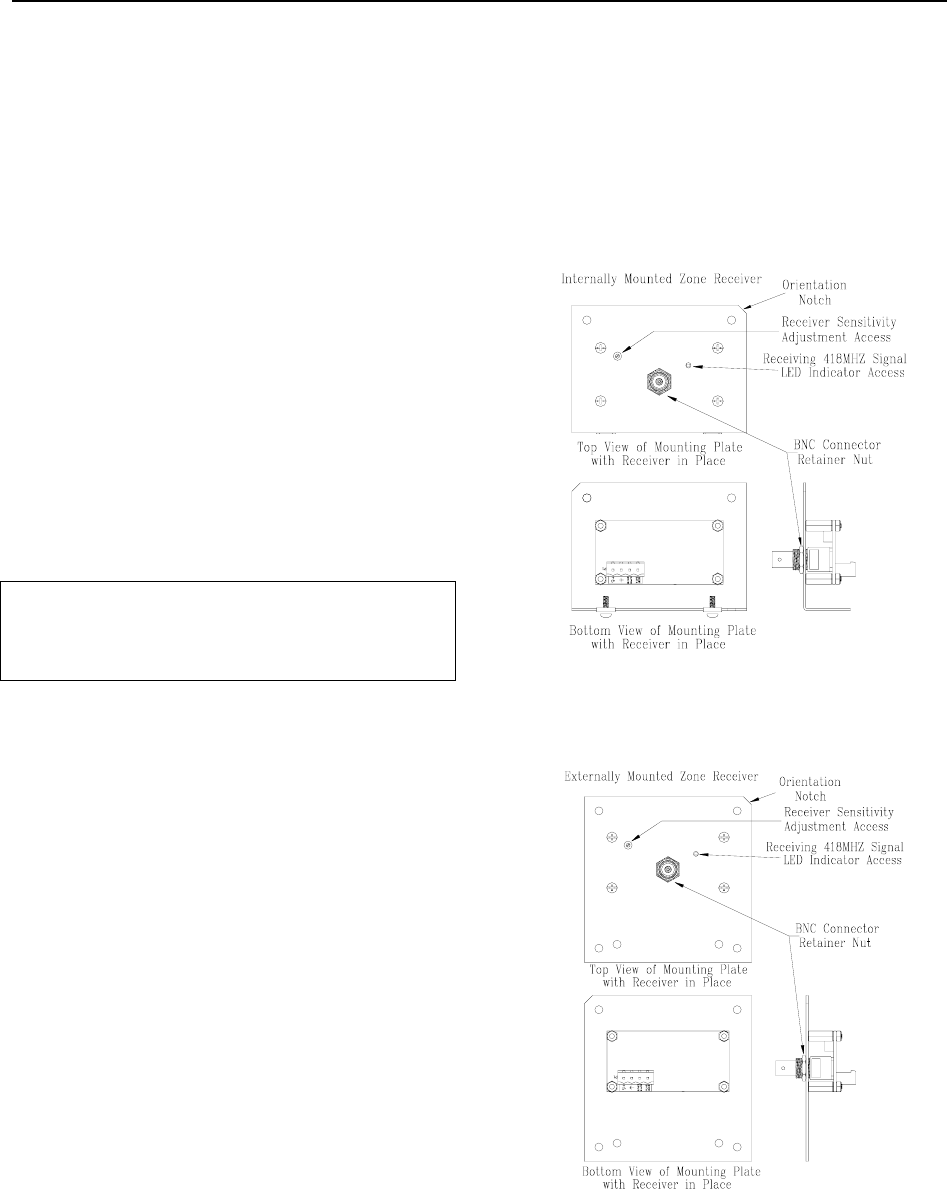
The ES 2100 Receiver (Figures A.1-A.2) located
at the monitored zone, picks up the signal from
an activated Tag and relays it to the Controller.
Zone Receivers can be internally or externally
mounted near a monitored zone.
Receiver Specifications
Power Requirements
Temperature
Weight
Power Requirements
6V DC
Temperature
Receivers operate best in an ambient
temperature between 35 and 90 degrees
Fahrenheit. Operation outside of this range may
cause unexpected or undesirable results,
including premature failure.
Weight
Internal and External Receivers weigh
approximately 5.0 oz. and 1 lb. 5.0 oz. U.S.
respectively, which should be considered when
choosing mounting hardware.
Figure A.1
Internally mounted ES 2100 Receiver
Figure A.2
Externally mounted ES 2100 Receiver
A-2 Appendix A: Discontinued Components Installation Manual
Internal vs. External Receivers
When the Controller is positioned near the
monitored zone, the Receiver is mounted
internally in the Controller housing.
When the Controller is positioned away from the
monitored zone, the Receiver is mounted at the
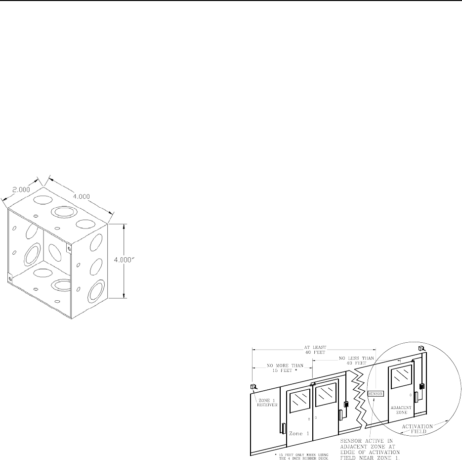
zone in a 4”x4”x2” electrical box.
Figure A.3 4”x4”2” electrical box
Keep in mind when the Controller is remotely
located, at least two 4”x4”x2” electrical boxes
are needed at the zone. One box is used to mount
the Receiver near the door as mentioned above
and the second box is used as a junction box for
the composite cable (where connections are
made to wires that “branch” to the individual
system components).
Receiver Mounting Options
If you receive your system equipment and
determine that the Receiver needs to be changed
from an Internal to External mounting or visa
versa, contact your Accutech Representative
about acquiring the proper faceplate.
Receiver Positioning/Stagger Tuning
Position the Receiver within approximately 6
feet of the center of the monitored zone or door
opening. It is permissible to mount it beyond 6
feet, but do not exceed 15 feet from the center of
the zone or door opening.
The recommended location for the Receiver unit
is up and out of the way such as above the
doorframe or above drop ceiling panels if
possible. Receivers monitor 40 feet outward in
every direction; therefore, they should be
positioned approximately 70 feet apart.
If the Receivers of adjacent zones need to be
closer than 70 feet (Figure A.4), implement
Stagger Tuning (page 4-6) to avoid crosstalk
(activated Tag from one zone being detected in
another zone).
Figure A.4 ES 2100 Zone Receiver spacing
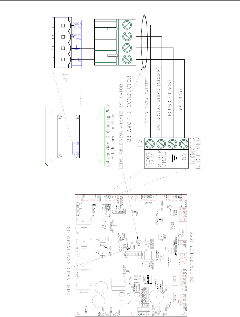
Connecting the Receiver
Whether internally or externally mounted, the
wire connections from the Receiver to the
Controller are the same (see Figure A.5).
NOTE: The internally mounted Receiver is
provided with a factory-installed interconnect
cable. There should be no reason to ever
disassemble it. If however it should need
replacement for any reason use an 18-inch piece
of 22-gauge 4-conductor non-shielded cable.
Installation Manual Appendix A: Discontinued Components A-3
Figure A.5
Connecting the ES 2100 Receiver to the Controller

A-4 Appendix A: Discontinued Components Installation Manual
Adjusting the Receiver
The Receiver is factory set for optimum
performance, and as such, it should not be
necessary for you to make any adjustments to it.
However, there are some exceptions:
When protecting a wide hallway, it may
be desirable to increase the Receiver
sensitivity to assure optimum detection.
When two or more zones are located in
close proximity (less than about 40 feet
apart), it may be desirable to decrease
the Receiver sensitivity to eliminate the
effects of crosstalk (activated Tags
from one zone being detected in
another zone).
To adjust a Receiver, refer to Figure A.1 or A.2
and use the following instructions:
1. Around the access hole for
potentiometer R11 on a Receiver, a
decal marks the minimum and
maximum settings. The factory setting is
approximately halfway between the
minimum and maximum marks. The
Receiver will not work outside these
marks. When adjusting, it is best to stay
within 1/16” of a turn of the factory
setting.
2. As you adjust, remember to verify that
there is adequate coverage (but no
crosstalk) in the zone and adjacent
zones.
3. To decrease the Receiver’s sensitivity,
slowly turn potentiometer R11
clockwise toward the minimum setting
on the R11 decal.
4. To increase the Receiver’s sensitivity,
slowly turn potentiometer R11
counterclockwise toward the maximum
setting on the R11 decal.
Installation Manual Appendix A: Discontinued Components A-5
Composite Cable (Part #200355)
Lock Cable
Technical Specifications
NOTE: For easier installation, Accutech
Composite Cable (Part # 200355) was
replaced with Composite Cable (Part #
200371) on June 1st, 2004 and is no longer in
production.
For information on the new composite cable
(Part # 200371), see page 2-2.
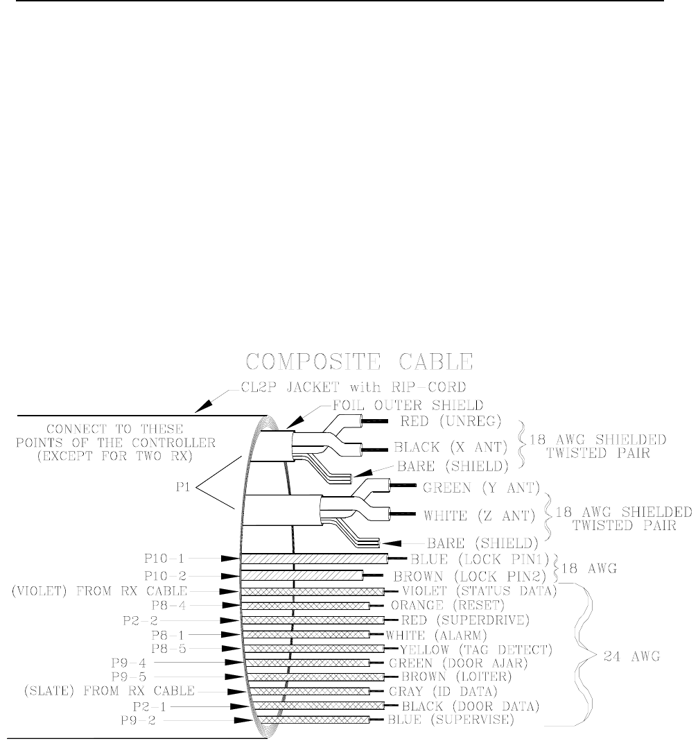
Accutech offers a “composite” cable (Figure A.7;
Part # 200355) for wire runs from the Controller
to a Junction Box when the Controller is
mounted away from the zone.
At the zone, use the cable kits supplied with the
system to run from the Junction Box to the
individual components at the zone.
When wiring composite cable, use the same
color code throughout the Accutech System
(Figure A.7).
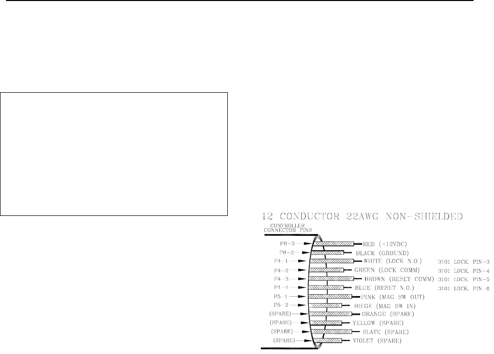
Lock Cable
If your installation includes a Lock, but it does
not have to comply with NFPA101, run 18-
gauge, 2-conductor from the Controller to the
Lock.
If your installation includes NFPA101 compliant
Locks, use 22-gauge, 12 conductor cable to
make the connection between the Controller and
the Lock (see Figure A.6 and Chapter 11).
Figure A.6 Lock Cable Color Code
A-6 Appendix A: Discontinued Components Installation Manual
Technical Specifications
The technical specification for Composite Cable (Part # 200355)
2 Pair of AWG x 7/.0152 T.C., 0.012 Teflon Color Code: black/red; green/white 0.001 polyester tape
binder over each pair, 18 AWG x 7/.0152 T.C. drain, 0.0015 aluminum/polyester shield, foil and drain.
2-Conductor 18 AWG x 7/.0152 T.C., 0.008 Kynar, Color Code: brown, blue.
10 Conductor 24 AWG x 7/32 T.C., 0.008 Kynar, Color Code: red, green, brown, blue, orange, yellow,
violet, gray, white, and black.
polyester binder over core
Nylon rip cord
0.020 black smoke guard jacket, 0.370 nominal O.D.
UL Type CL
Figure A.7 Composite Cable (Part # 200355) Conductor Uses and Color Code
Installation Manual Appendix A: Discontinued Components A-7
Tag styles (gray and/or yellow colored)
ES 2200 System Tags
IS 3200 System Tags
BR 4200 System Tags
NOTE: Gray and/or yellow Tag case styles are
no longer in production and are replaced
with bar-coded Tag case styles. For more
information, see Chapter 6.
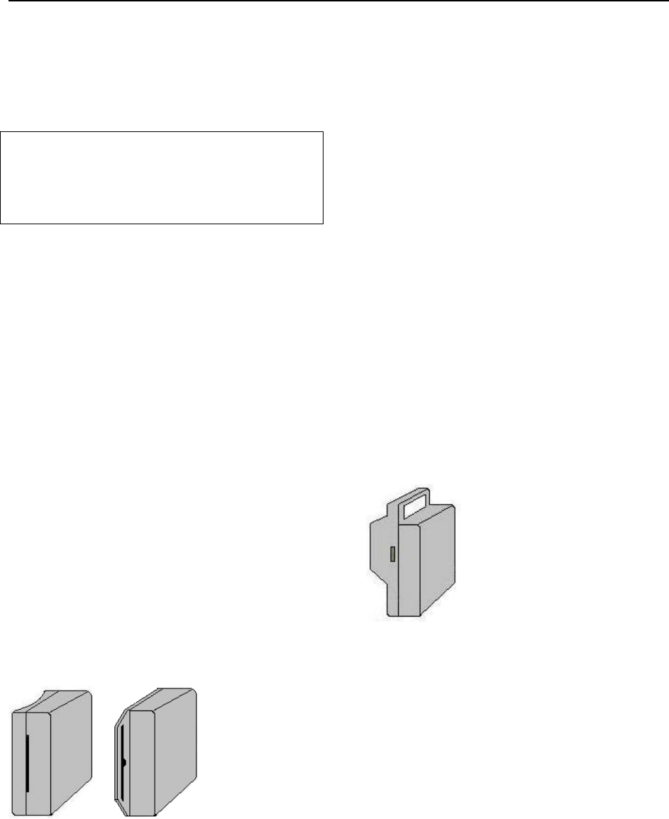
ES 2200 System Tags
ES 2200 System Tags (Figure A.8) are small
wristwatch-sized devices worn by a resident or
attached to an asset. When a resident or patient
enters a Tx Activation Field, the Tag sends a
signal to the zone Controller, via the Receiver.
The zone Controller processes this information
for appropriate control action or response (e.g.
sounding alarms, locking doors, etc.).
The ES 2200 System Tag band is made of
nylon-reinforced vinyl with nylon mesh. The
band is designed to resist tearing caused by
pulling or chewing on the band. However, if the
band becomes frayed or torn it will need to be
replaced. In long-term applications, the band
should be replaced periodically for cleanliness.
or
LT22/LT32 SB22/SB32
Figure A.8
The ES 2200 and IS 3200 System Tags
(bands not shown)
IS 3200 System Tags
In addition to the look and functionality of an ES
2200 System Tag, IS 3200 System Tags (Figure
A.8) are assigned to a specific resident or asset
(via the Tag Test Station and Accutech
Software). Once assigned, the computer
associates a name, room number and any other
pertinent information about the resident/asset
with that Tag.
BR 4200 System Tags
In addition to the functionality of an IS 3200
System Tag, BR 4200 System Tags (Figure A.9)
will alarm if the band is removed or tampered
with in any way.
BR 4200 System Tags are attached to infants
with a conductive- fiber-striped cloth band.
BR42
Figure A.9 The BR 4200 System Tag
(band not shown)
Testing Tags
For maximum protection of residents or assets,
Accutech recommends Tags be tested on a
weekly basis. There are 4 ways that you can test
a Tag: enter a monitored zone, a TAD (Part
#660021), a Tag Test Station (TTS), and/or the
Keypad’s Auxiliary LED (yellow) will light
when a Tag is detected (optional, additional wire
required).
A-8 Appendix A: Discontinued Components Installation Manual
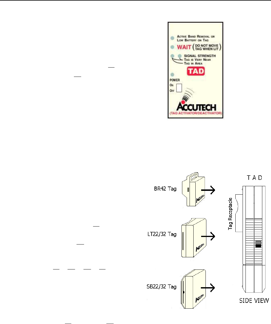
Activating/Deactivating Tags
NOTE: The “Tag Signal Strength” LEDs of the
TAD (see Figure A.10) indicate the current state
of a Tag. Illuminated indicates the Tag is on;
dormant indicates the Tag is off or is not
functioning.
1. With no Tag in the TAD, slide the
Power switch to the On position
The TAD Power LED illuminates.
If not, replace the TAD 9-volt battery
and turn on the TAD.
NOTE: If a Tag is in the receptacle and
the power to the TAD is cycled, the Tag
may be turned on or off unintentionally.
2. Place the Tag into the tag receptacle on
the back of the TAD unit in proper
orientation for the Tag type (see Figure
A.11)
NOTE: If the “Tag Signal Strength”
LEDs illuminate, the Tag is on. If the
“Tag Signal Strength” LEDs do not
illuminate, the Tag is off.
3. To change the state of a Tag
(from either on to off or off to on),
press and release the TAD button
The WAIT LED will illuminate for about
a second.
The “Tag Signal Strength” LEDs will
change according to the state change
(illuminating for on, dormant for off).
Figure A.10: The TAD front label
NOTE: The Power switch for your TAD may be
located on the left side or top of the unit.
Figure A.11: Proper Tag Orientation

Installation Manual
Appendix B:
Jumpers, LEDs, Pots, Switches & Fuses