Inomatic AMTEK 58KHz ACOUSTOMAGENETIC EAS System(TX, RX, Mono) User Manual
Inomatic (Suzhou) Technology Co.,Ltd. 58KHz ACOUSTOMAGENETIC EAS System(TX, RX, Mono)
Inomatic >
User Manual

AMTEK
250/350/700/750/800
Operation Manual
58kHzAcousto-Magnetic EAS System
valid
for
AM Pro-Line electronics
(TX/RX)
Hardware Version AMPRO 700V7.3, Firmware Version
AT1.2

Confidential
AMTEK Version 7.3F 2015-11
Page 2
©Inomatic 2015
SAFETY
GUIDELINES
Any manipulation of the system should be done by qualified and
trained personnel only.
Do not open the AMTEK system‟s power supply when connected to
power! High voltage!
Do not touch the antenna wire or matching circuit when connected to
power! High voltage!
Before changing blown fuses or manipulating the antennas, always
disconnect from 120V power source first!
Do not plug in or out the power supply cables to or from the
processor board unless the power supply is switched off!
Do not insert or take-out any jumpers unless the power supply is
switched off!
Route the RX-TX cable and power supply cables through places
where they cannot be easily damaged!
Do not use the system in water condensing conditions!
Do not use the system in explosive environmental conditions!

Confidential
AMTEK Version 7.3F 2015-11
Page 3
©Inomatic 2015
LIST OF CONTENTS
SAFETY GUIDELINES .................................................................................................... 2
1. Introduction............................................................................................................... 5
1.1. System Description............................................................................................. 5
1.2. Typical System Performance .............................................................................. 6
1.3. Additional Features............................................................................................. 6
2. AMTEK System ........................................................................................................ 8
2.1. Component Overview ......................................................................................... 8
2.1.1 Electrical Specifications: ..................................................................................... 8
2.2. Processor Board AMPRO 700V7.3 .................................................................... 9
2.3. Receiver Board AMRB 700V5.1 ....................................................................... 11
2.4. RX-TX-Connection Cable AMCTR 710 ............................................................ 12
2.5. Dual Power Supply AMPSS 700V6 .................................................................. 13
2.5.1 Power supply cable/connector ................................................................... 15
2.6. System Configurations ..................................................................................... 16
2.6.1. Dual System............................................................................................... 16
2.6.2. Split System ............................................................................................... 17
3. System Installation ................................................................................................. 18
3.1. Noise sources................................................................................................... 18
3.2. System Part List ............................................................................................... 18
3.3. Installation Requirements ................................................................................. 19
3.4. Installation Procedure ....................................................................................... 20
4. Tuning of the Matching Circuits .............................................................................. 21
4.1. TX Antenna Matching ....................................................................................... 21
4.2. Matching capacitors default setting: ................................................................. 23
4.3. RX Matching Circuit .......................................................................................... 24

Confidential
AMTEK Version 7.3F 2015-11
Page 4
©Inomatic 2015
5. Synchronization ...................................................................................................... 25
5.1. AM operating principle................................................................................... 25
5.2. Synchronization principle .............................................................................. 26
5.3. Hardware Synchronization ................................................................................ 28
6. LAN Connection ..................................................................................................... 31

Confidential
AMTEK Version 7.3F 2015-11
Page 5
©Inomatic 2015
1. INTRODUCTION
1.1. System Description
The AMTEK range of Acoustomagnetic EAS Systems is fully compatible with all
58 kHz tags and Acustomagnetic labels on the market.
The systems are designed to get optimum detection performance and to avoid false
alarms at the same time by using digital signal processing and anti-noise algorithm.
The AMTEK systems can be operated in 2 configurations:
1.)
Dual system
1 Transmitter and 1 Receiver antenna
2.)
Split system
1 Transmitter and 2 Receiver antennas
Working principle: A 58 kHz pulsed magnetic field is generated between the
Transmitter (TX) antenna and one or two Receiver (RX) antennas. Any 58 kHz AM label
or hard tag brought into the magnetic field will generate a signal which can be detected
by the Receiver antennas and subsequently trigger an alarm signal.
F40 tag Mini Pencil
Super tag II DR label
Picture 1.1 - AM Hard Tags and Labels

Confidential
AMTEK Version 7.3F 2015-11
Page 6
©Inomatic 2015
1.2. Typical System Performance
Depending on the AM tags used and the installation environment, the detection distance
can vary. The following table gives an overview of typical detection ranges with the
different AMTEK systems and security elements.
Distances(m)
AMTEK 250
AMTEK 350
AMTEK 750
F40 tag
2.5
2.6
2.5
Mini Pencil
2.2
2.3
2.2
Super tag II
1.8
1.9
1.8
DR label
1.2
1.9
1.8
1.3. Additional Features
All Version AMTEK V7.3 systems are equipped with 2 additional alarms that allow an
easier handling of certain situations.
The Jammer alarm indicated that the system is compromised by a jammer signal.
The alarm light and buzzer sequence for Jammer alarm can be set via InfoNet software.
In this case the detection of the system is disabled to avoid false alarm.
The Near Tag alarm is triggered by a continuous detection of a stationary security
element in the detection zone. The alarm light and buzzer sequence for Jammer alarm
can be set via InfoNet software. By enabling the Near Tag alarm, one can easily detect
tags that have accidentally been placed inside the
system‟s
detection area.
Both of the above described alarm features can easily be enabled/disabled by activating
the respective checkbox inside the InfoNet software.
Programmable on/off time:
The system can be automatically switched on/off at certain times. The time for ON and
OFF can be set via the InfoNet software. The system will consume much less power
during OFF time (Energy saving)

Confidential
AMTEK Version 7.3F 2015-11
Page 7
©Inomatic 2015
Incoming/outgoing alarm (only with integrated visitor counter):
The system is able to distinguish between incoming and outgoing alarm if equipped with
the optional integrated visitor counter. The alarm indication is different for the two types
of alarms allowing easy identification of incoming and outgoing alarm.
Firmware update:
If a new firmware becomes available, the
processor‟s
firmware can be updated via the
InfoNet software allowing update of new system features without replacing the
electronics.
Selection of light/sound sequence:
The system alarm light and sound can be programmed in different sequences. Different
aisle could have different sound sequence enabling the identification of where the alarm
came from. It is also possible to have the alarm light on longer than the alarm sound to
easily identify the alarm position. For multi aisle installation this feature is especially
useful.
Remote Tuning/Service/Monitoring
In order to reduce the need for service calls, especially for remote places, our PRO-
LINE systems can be accessed via Internet. The system service provider can log-in
from their office into the system via infoNet Cloud (provided they are authorized) and
diagnose/solve potential problems.
Integrated bidirectional visitor counter
Possibility to count customers per aisle and to determine the direction of
movement (in or out of the shop)
Showing the importance of the alarm (is a customer moving in or out during the
alarm)
Detecting undefined alarms
Pinpoint the exact aisle where the alarm occurred
Generate reports on visitor counts and alarm counts

Confidential
AMTEK Version 7.3F 2015-11
Page 8
©Inomatic 2015
2. AMTEK SYSTEM
2.1. Component Overview
The standard system comprises the following components:
a.) Processor Board AMPRO 700V7.3
b.) Receiver Board AMRB 700V5 or higher
c.) Power Supply AMPSS 700V6 or higher
d.) Antenna AMTEK 250/350 or AMTEK 750/800
e.) Connection Cable TR AMCTR 710
f.) Computer Cable LAN Cable AMCOM 710
g.) infoNet Software infoNet V4or higher
Please note that the Version 7.3 processor board hardware can come with
different Firmware Versions. Please check the label on the processor if you are
not aware of your
board‟s
firmware version.
2.1.1 Electrical Specifications:
Power supply -Output 40VDC/ 600mA or 18VDC/400mA
-Input 100-240VAC, 50/60Hz
100VAC/0.31A Transmitter Operating Frequency 58 kHz (±200Hz)
Transmit Burst Duration 1.5ms or 1.6ms
Max. Transmit Current 12A peak
Transmitter Coil Resistance 2.7 ohm (±5%)
Burst Repetition Rate 50Hz
Receiver Center Frequency 58 kHz
Receive Coil Resistance 4.0 ohm (±5%)
Alarm Audio level 95dBA
Environmental Ambient Temperature 0°C to 50°C
Relative Humidity 0 to 90% (Non-condensing)
Confidential
AMTEK Version 7.3F 2015-11
Page 9
©Inomatic 2015
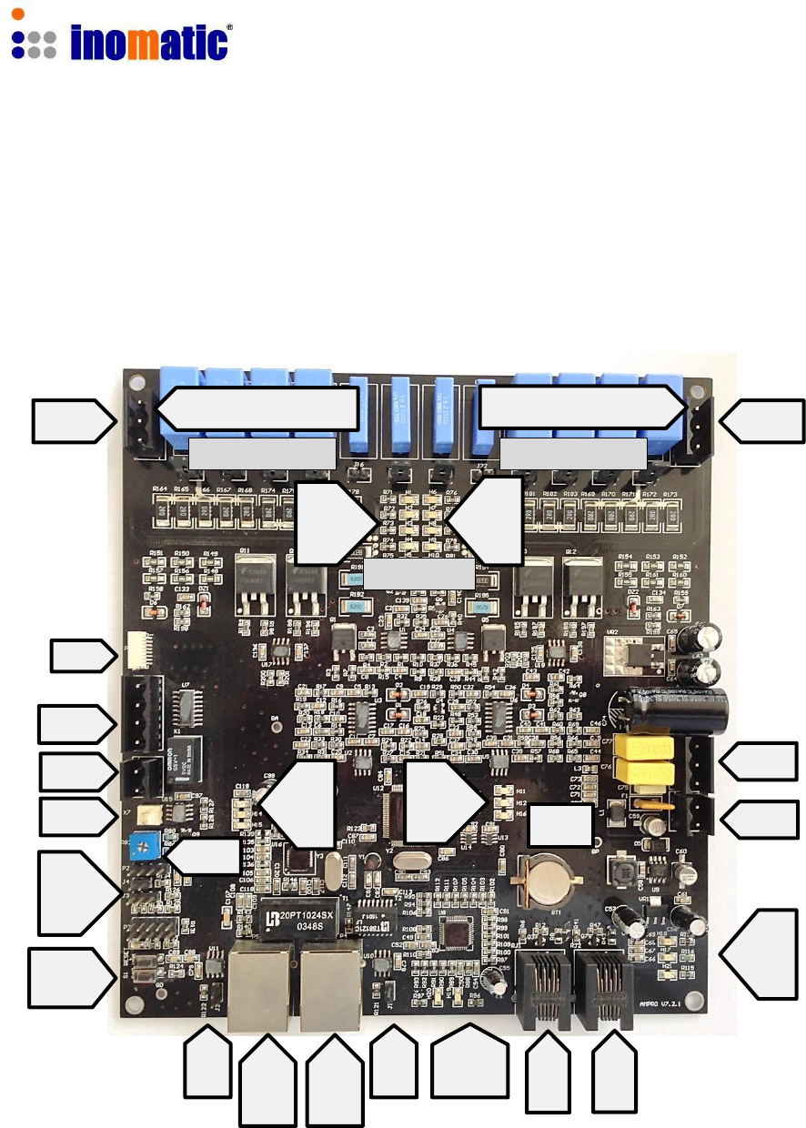
2.2. Processor Board AMPRO 700V7.3
The picture below shows a top view of the TX board. Table 2.2 lists the board‟s relevant
connectors and tuning components together with their functions.
Matching upper coil Matching lower coil
X3 X4
J1 to J6 J7 toJ12
H1
to
H5
TX1
TX2
H6
to
H10
P1
X5
X6
X7
J13
J14
J15
Reset
S1
R82
H11
H12
H13
H14
H15
H16
BT1
X1
X2
H19
H20
H21
J17
LAN
1
LAN
2
J18 H17
H18
RC RC
1 2
Confidential
AMTEK Version 7.3F 2015-11
Page 10
©Inomatic 2015
Table 2.2 - TX board's relevant components for connection and tuning
Component
Function
Component
Function
X1 & X2
Powers supply
RC1
Receiver channel 1
X3
Upper TX loop connection
RC2
Receiver channel 2
X4
Lower TX loop connection
TX1
LED bar for upper TX loop
X5
LED Alarm Lights
TX2
LED bar for lower TX loop
X6
Relay output NO contact
LAN1
Switch port 1
X7
Buzzer connector
LAN2
Switch port 2
J13
Factory use
H19
12V power supply
J14
Download Firmware
H20
5V power supply
J15
Master/Slave selection
H21
3.3Vpower supply
J16
Factory use
H14
Indicator for Internet
J17&J18
Sync bus termination
H15
Flashing Normal Operation
BT1
Real Time Clock battery 3V
H16
Indicator for Master/Slave
R82
Buzzer Volume
H11 – H13
LAN switch indicators
H17 – H18
LAN Data indicators
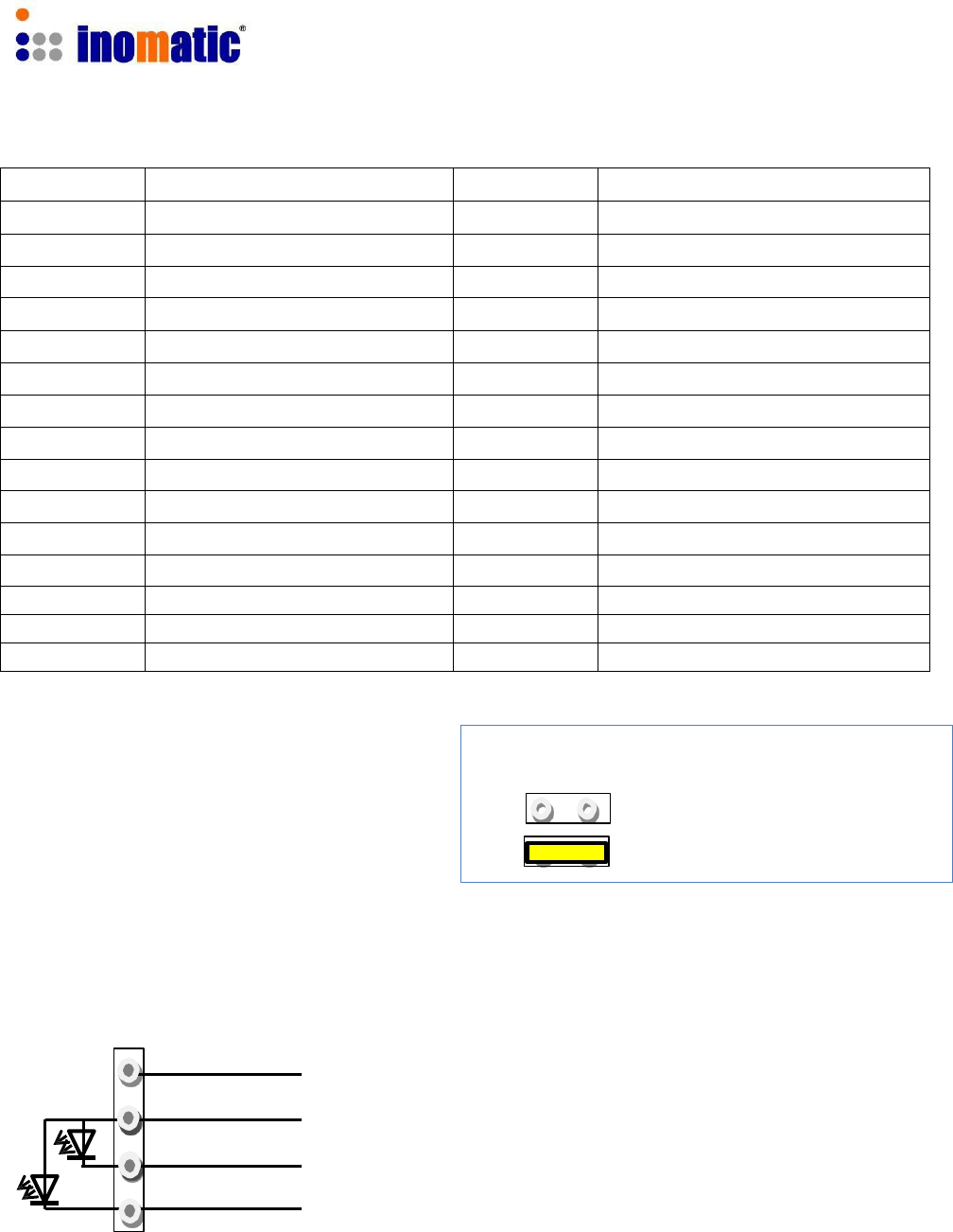
Jumpers 14 (Download Firmware) 1 2
The firmware of the AM Processor
board V7.3 can be updated via the
infoNet software.
For more details see Software Manual V4.2
LED Light connector X5
Normal Operation
Download Firmware
The AM Pro-line V7.3 board allows the connection of a two color LED top-light.
GND
+12V
LED1
LED 2
Confidential
AMTEK Version 7.3F 2015-11
Page 11
©Inomatic 2015
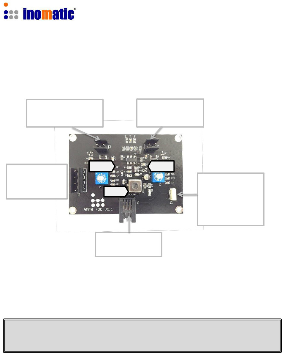
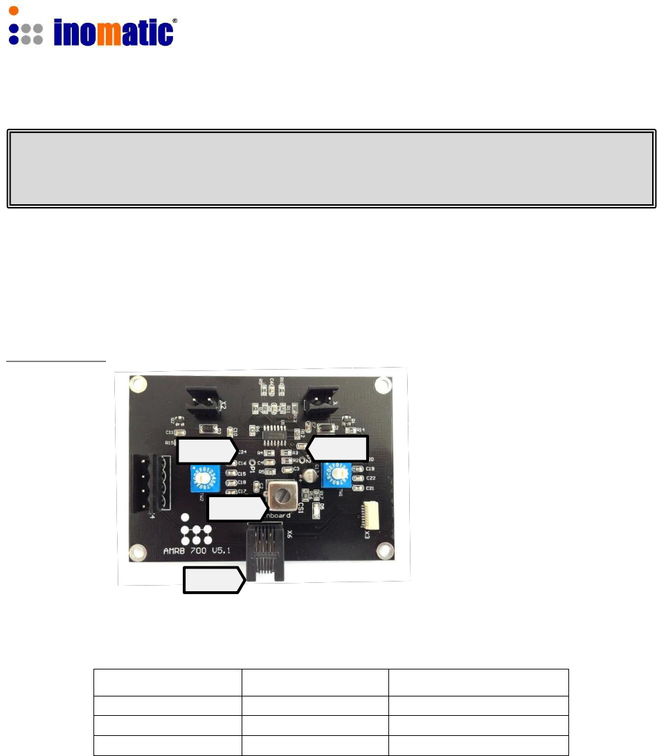
2.3. Receiver Board AMRB 700V5.1
Picture 2.3 below shows the RX board and the relevant components:
X2 - Lower receiver
loop connector
X1 - Upper receiver
loop connector
X4 - Alram Lights
TW2 TW1
CS1
X3 –Integrated
Visitor counter&
Alarm light
X6 - Connector to
Processor board
Each RX board controls the resonance of two loops in the RX antenna. The matching
for the upper and lower receiver loop can be adjusted through the 2 rotary switchesTW1
and TW2. TW1 adjusts the matching for the upper loop and TW2 adjusts the matching
of the lower loop.
All our antennas are pre-tuned in the factory and RX antenna matching WILL NOT
HAVE TO BE ADJUSTED in almost any case. When installing the system near
metallic frames or metallic doors, resonance value may be affected.
In this case, the RX matching can be modified for the upper and lower loop using the
rotary switches TW1 and TW2.

Confidential
AMTEK Version 7.3F 2015-11
Page 12
©Inomatic 2015
LED Light connector X4
The AM Pro-line V5 Receiver board allows the connection of a two color LED top-light.
GND
+12V
LED1
LED
2.4. RX-TX-Connection Cable AMCTR 710
The AMCTR 700 connection cable is supplied together with the RX antenna. It connects
the receiver board with the processor board of the TX
pedestal. Connect one end of the cable to the RX board (X6)
and the other end to the TX board (RC1 orRC2).
To avoid noise capturing, the connection between the RX and
TX antenna should be as short as possible.
Picture 2.4 - AMCTR
710
Connection
Cable
Confidential
AMTEK Version 7.3F 2015-11
Page 13
©Inomatic 2015
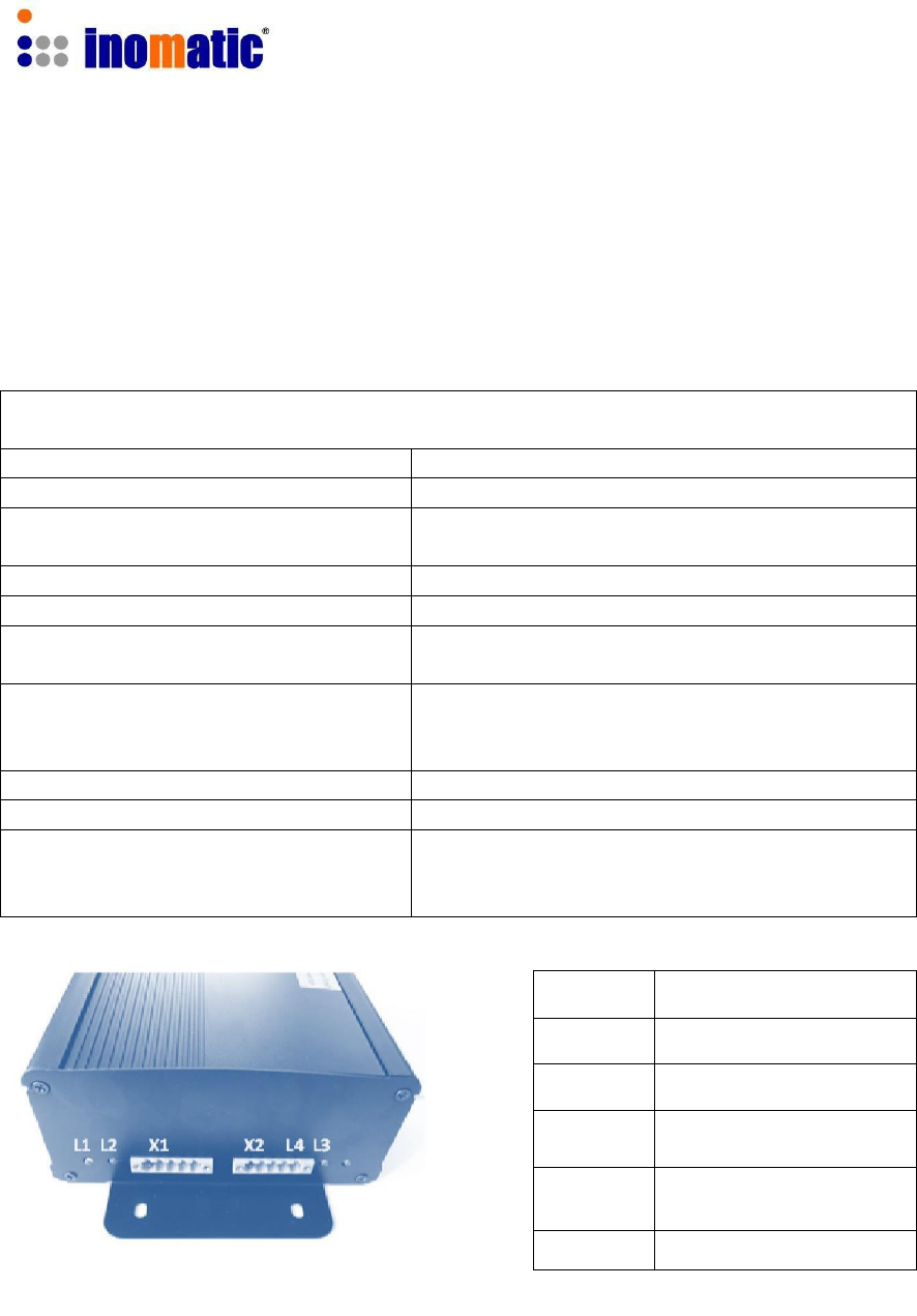
2.5. Dual Power Supply AMPSS 700V6
The Dual power supply AMPSS700V6 is used for all our AM systems using V4 or V6
processor boards. It provides the power and the Synchronization signal to the system
electronics for maximum 2 TX antennas.
Technical specifications for AMPSS 700
Dimensions (L x W x H)
210 x 150 x 70 mm
Weight
3.0 kg
Input voltage / frequency / current
100-240VAC,50 / 60Hz
Mains inlet type
AC IEA with ON/OFF switch
Output voltage
40VDC and 18VDC
Output cable
5x1mm2, 8m length. This cable can be
extended to 15m using a 3x1mm2 cable or
thicker.
Temperature range
0 – 50C
Primary fuse (FP)
220VAC – 1A slow , 100VAC – 2A slow
Secondary fuses:
(Inside the housing)
F1 (40V, 3A), F2 (18V, 3A)
F3 (18V, 2A), F4 (40V, 2A)
F5 (18V, 2A), F6 (40V, 2A)
X1
Power Processor board 1
L1
40VDC (LED red/blue)
L2
18VDC (LED red/blue)
X2
Power Processor board 2
L3
40VDC (LED red/blue)
L4
18VDC (LED red/blue)
AMPSS 700 V6 power supply
If any LED lights “red” means the respective voltage is missing
Confidential
AMTEK Version 7.3F 2015-11
Page 14
©Inomatic 2015
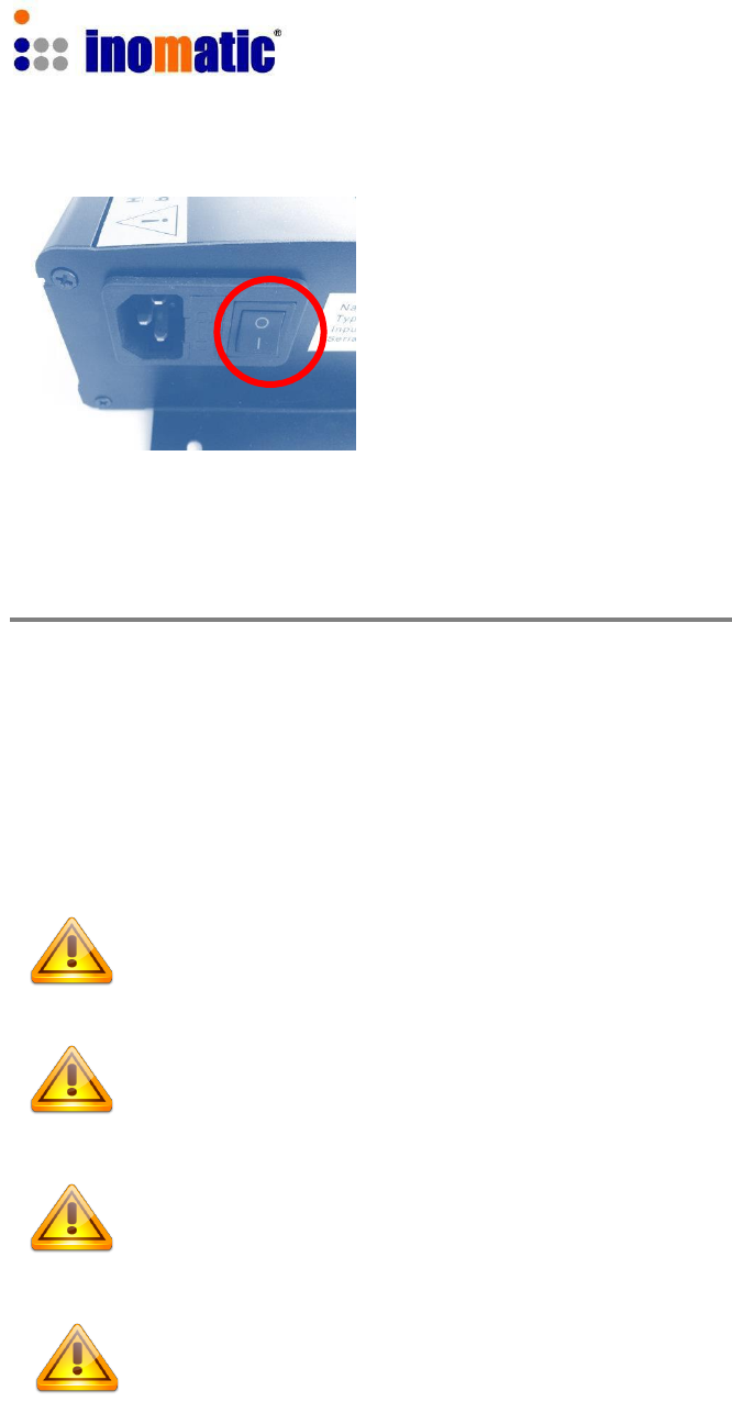
To operate the power supply, connect the power
FP supply via the main power cable to a main
power outlet and switch on the main switch SM.
Make sure the “Earth” of the power plug is connected
to the power socket.
The AMPSS700V6 has 2 system power outlets (X1 and X2)
The output cable of the power supply is connected to the processor board through
1 x 3 pin and 1 x 2 pin connectors.
If the connector needs to be removed for some reason, the color code of the cables
must be observed. To avoid damages to the power supply and to the system electronics
replace the fuse with the same kind of fuse if necessary.
If any fuse needs to be changed always unplug the power supply
from the AC source first.
Always connect the power supply to the system first before switching on
the power supply.
Always switch off the power supply first before disconnecting the power
supply to the system.
Local laws and regulations must be respected when installing and
servicing this device
Confidential
AMTEK Version 7.3F 2015-11
Page 15
©Inomatic 2015
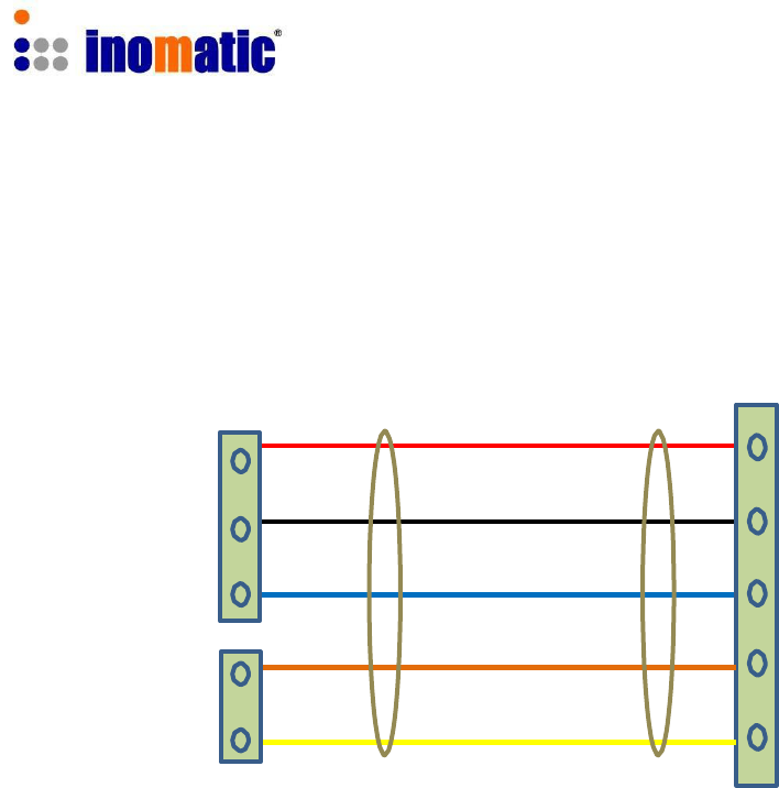
2.5.1 Power supply cable/connector
V7.3 Processor board Power supply V6 (X1 or X2)
RED
40VDC
X1 BLACK GND
BLUE
18VDC
X2
Picture 2.6
BROWN Sync
YELLOW GND
Please note that the power supply cable between the power supply and the processor
board should not exceed 15 meter.
Confidential
AMTEK Version 7.3F 2015-11
Page 16
©Inomatic 2015
AM
PSS
700
To X1 & X2
2.6. System Configurations
One processor board (TX) can drive one or two RX antenna(s), thus resulting in two
configuration modes: “Dual and Split system. The following gives a schematic overview
about the necessary components and connections for both configurations.
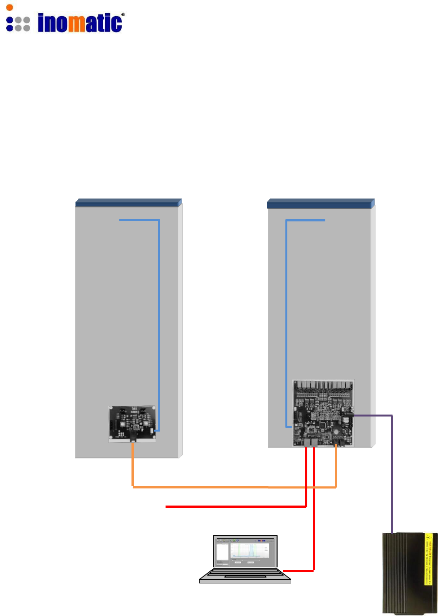
2.6.1. Dual System
RX antenna TX antenna
LED light LED light
AMCTR 710
Shop -LAN
LAN Port
Hardware synchronization might only be necessary, if 2 or more TX antennas are used.
Confidential
AMTEK Version 7.3F 2015-11
Page 17
©Inomatic 2015
AM
PSS
700
To X1 & X2
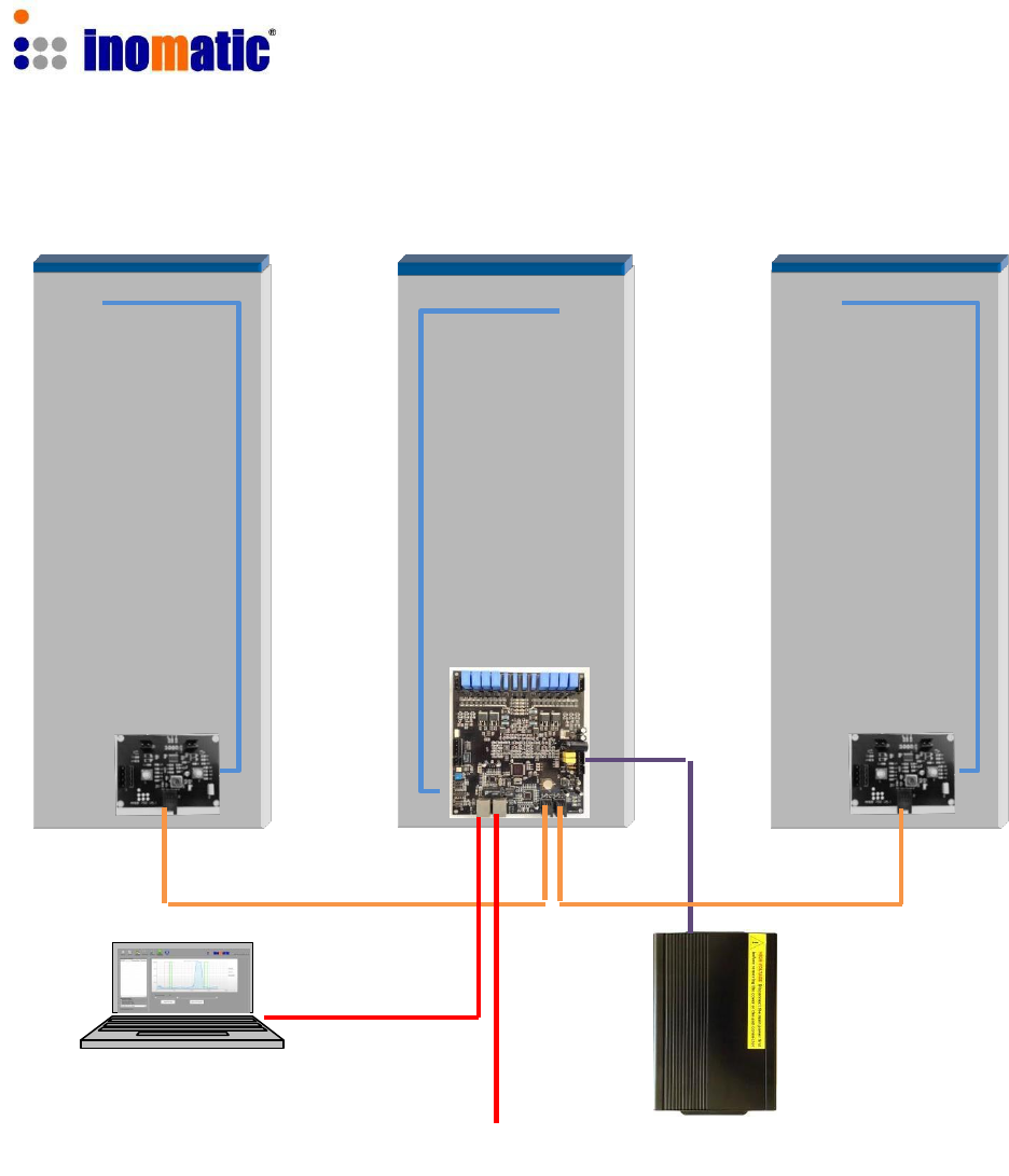
2.6.2. Split System
RX antenna TX antenna RX antenna
LED light LED light LED light
AMCTR 710 AMCTR 710
LAN Port
Shop
-LAN
To reduce any noise influence, make sure:
1.) To place the power supply as close as possible to the TX antenna.
2.) To have the connection between the RX and the TX antenna (AMCTR 710
Connection Cable) as short as possible.
Hardware synchronization might only be necessary, if 2 or more TX antennas are used.

Confidential
AMTEK Version 7.3F 2015-11
Page 18
©Inomatic 2015
3. SYSTEM INSTALLATION
This chapter covers the various issues related to Acoustic Magnetic systems and
Electronic Article Surveillance systems in general, like:
Noise sources
Installation guidelines
3.1. Noise sources
Below there are various noise sources listed that might affect the performance of any
EAS system. It is strongly recommended to either eliminate these noise sources (as far
as possible) or maintain the largest possible distance to these noise sources.
The following devices can create or absorb AM noise signals which can reduce the
performance of an EAS system:
AM systems installed in other shops (even if they are installed up to 100m or
more away from your store).
Any electronic device that operates around 58 kHz or produces harmonic
frequencies around 58 kHz.
An active laptop. The back light in the screen can create a lot of noise which is
detected by the EAS system and can reduce the performance dramatically. Make
sure to keep laptop computers at least 3 meters away from the antennas.
(Moving) Objects containing metal, like sliding and revolving doors, elevators,
escalators, roller shutters, frames, etc.
Electronic devices, like computers, laptop screens, LCD screens, cash registers,
engines, transformers, etc.
Vertically positioned power cables, both low voltage and high voltage.
Lights (flashing, fluorescent, halogen, gas-de-charge, etc.)
Metal scan systems installed in close vicinity.
3.2. System Part List
a.)
2x Pedestal AMTEK
(1 TX and 1 RX)
b.)
1x Power supply
AMPSS 700V6
c.)
1x Connection cable TR
AMCTR 710
d.)
1x Computer Cable
LAN Cable AMCOM 710
e.)
1x Computer software
infoNet V4 or higher

Confidential
AMTEK Version 7.3F 2015-11
Page 19
©Inomatic 2015
3.3. Installation Requirements
Make sure all parts have arrived. Make sure there are no damaged parts. If there
is any damaged part, notify the transport company.
Installation shall be performed by a qualified installer with all necessary
national/local electrical/fire codes training.
If possible, connect a set of antennas (1 TX and 1 RX) and put them in the
required position in the entrance/exit without drilling holes in the floor and bolting
the antennas down. Switch on the system and test the performance. In this way
the noise level and system sensitivity can be determined and if necessary (in
case of high noise or poor sensitivity) the system can be moved to find a better
position
The pedestals shall be placed at a distance equal to or smaller than the
maximum value depending on the kind of tag.
Avoid placing TX/RX pedestals near metallic structures (doors, frames, etc...) or
neon/discharge lamps.
Metal framed doors may never swing between the EAS antennas, as this will
distort the energy field of the system in such a way that it might result in high
noise, poor detection and potential false alarms
Always install the TRX antenna on that side where the highest noise is or where
the highest noise can be expected.
Not connected RX antennas nearby a running system are to be avoided. They
act as a big hard tag.
No power line (including power supply or TX antenna power line) shall be located
in the same pipe/tube with the TX-RX interconnection cable.
Avoid unnecessary long cables. Run the power supply cables in a direct line to
the EAS antennas. Never run power supply cables vertically up the wall within
one meter distance of the antennas (never around the entrance/exit doorframe).
The AC source should be a clean AC source. If possible do not share the AC
source with computers, neon lights/discharge lamps, or equipment with switching
power supplies, make sure the “Earth” of the power supply plug is connected to
the power supply socket.
Blown fuses shall be replaced with fuses of the same kind.
ALWAYS UNPLUG power supply BEFORE CHANGING blown fuses!

Confidential
AMTEK Version 7.3F 2015-11
Page 20
©Inomatic 2015
3.4. Installation Procedure
Remove base covers from pedestals.
Electronics will now be visible. Confirm all connections are firmly in place.
Place TX pedestal in the place to be installed.
Consider the position of AC 120V/60Hz power source. Ensure that 120V 60Hz
AC source can be connected with the Power Supply and that the Power Supply
output cable can be connected with the TX pedestal.
Avoid placing TX/RX pedestals very near metallic structures (doors, frames,
etc...) or neon/discharge lamps and LED, LCD monitors.
Place RX pedestal at the place to be installed.
It is strongly recommended to tune the system to its final working conditions
BEFORE drilling any hole! Depending on tag type, RX pedestal can be placed at
different distances from TX pedestal (See “System Performance” on page 6).
Connect RX pedestal to TX pedestal using the connection cable
AMCTR 710
Confirm all connections to the loops, receiver board, and processor board
are firmly in place.
Before turning the system on, remove all 58 kHz tags near to it.
Connect Power Supply to the TX processor board with the 2-pin and 3-pin
connectors
Connect Power Supply to AC 120V/60Hz source, switch on the power
supply.
Connect the computer via the LAN cable and start
InfoNet software (for tuning please refer to the InfoNet manual)
Confidential
AMTEK Version 7.3F 2015-11
Page 21
©Inomatic 2015
4. TUNING OF THE MATCHING CIRCUITS
4.1. TX Antenna Matching
All our antennas are pre-tuned in the factory and the TX Antenna matching WILL
NOT HAVE TO BE ADJUSTED manually in almost any case. When installing the
system near metallic frames or metallic doors (which is not recommended), the
resonance value may be affected and manual matching is required.
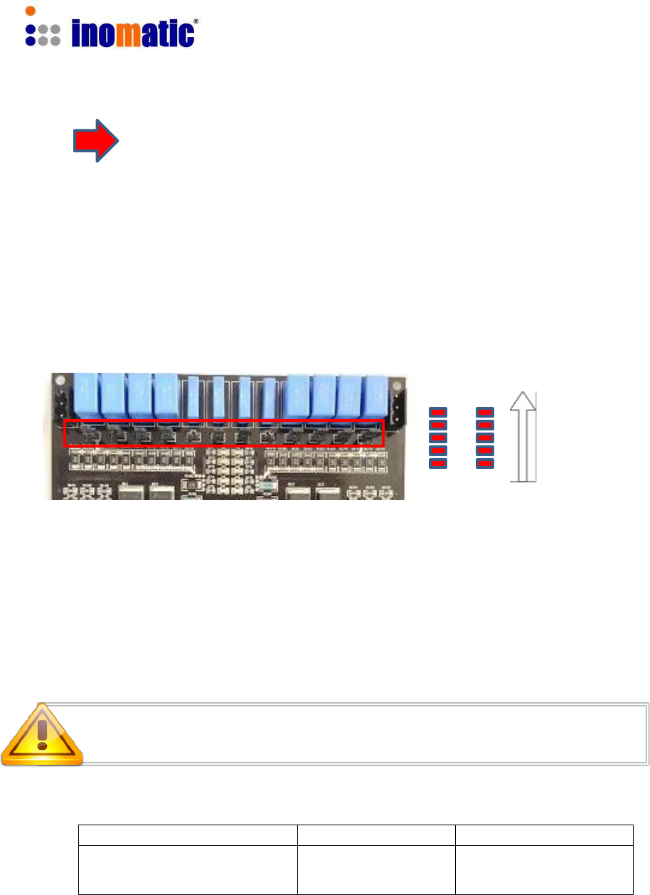
The LED bars TX1 and TX2 should light up completely when the
system is powered on.
If the LEDs do not light up at all, then check:
Whether “TX block” is activated by the respective checkbox inside the infoNet
Software (see infoNet Manual for further details).
De-Activate the TX block if not done yet.
The LEDs should light up now.
Confidential
AMTEK Version 7.3F 2015-11
Page 22
©Inomatic 2015
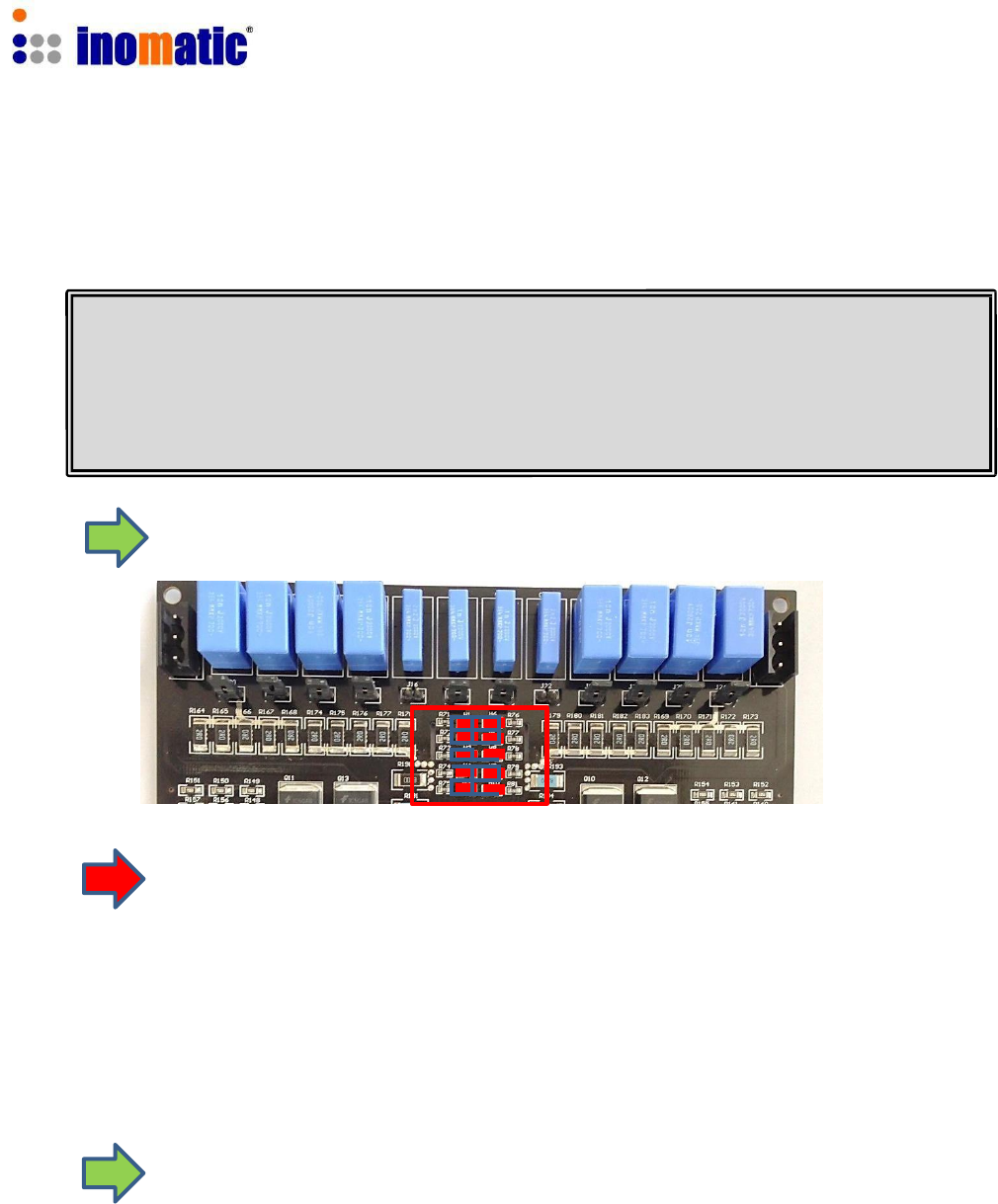
If the LED bars do not light up completely on one or both sides, then:
It is necessary to adjust the matching of the antenna loops. The AMTEK700V6
processor board is designed to be used for all AMTEK systems. Since every
AMTEK system shows slightly different antenna characteristics, the board allows
the selection of different capacitors for each antenna loop by inserting the
respective jumpers. The matching capacitors are located at the upper part of the
board.
The matching Level is shown by the LED bars TX1 and TX2:
TX1 TX2
Increasing
quality of
matching
If the antenna is mismatched, not all of the 5 LEDs of LED bars TX1 and TX2 will light
up. In that case, the TX resonance of the upper and lower loop can be modified by
changing the matching capacitance through the 6 jumpers in the relevant
matching circuits (refer to default setting below).
Switch off the power first before you change any jumpers!
Wait a while for the capacitors to discharge! High voltage!
Function
Relevant jumpers
Associated LED bar
Matching of the upper loop
J1 to J6
TX1
Matching of the lower loop
J7 to J12
TX2
Table 4.1 – Jumpers for matching of TX antenna
Confidential
AMTEK Version 7.3F 2015-11
Page 23
©Inomatic 2015
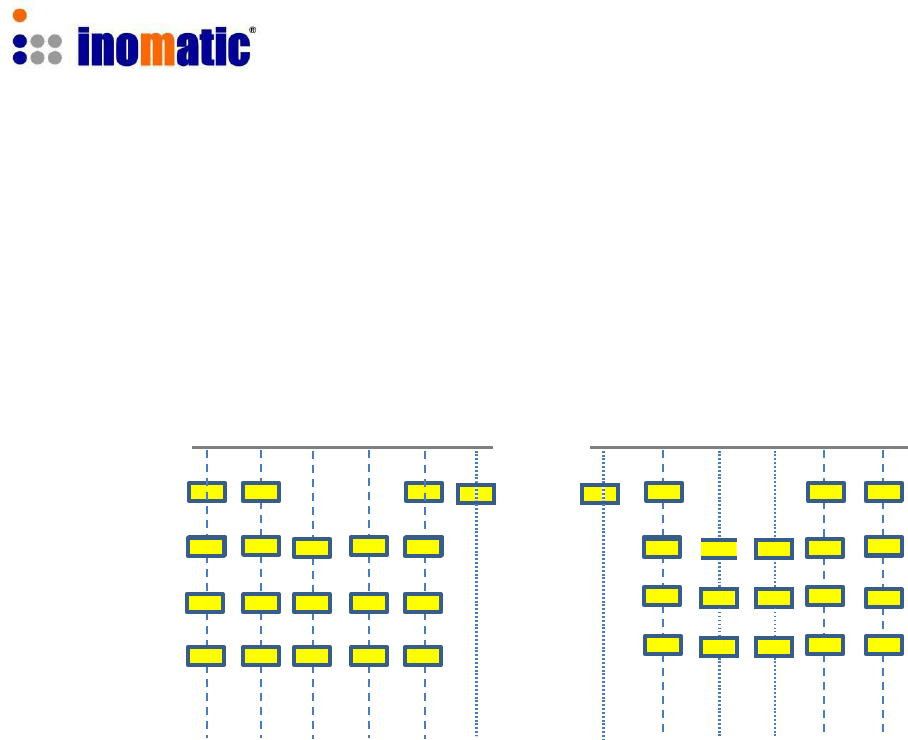
4.2. Matching capacitors default setting:
Upper antenna loop Lower antenna loop
J1 J2 J3 J4 J5 J6 J7 J8 J9 J10 J11 J12
AMTEK 250
AMTEK 350
AMTEK 800
AMTEK 750
Confidential
AMTEK Version 7.3F 2015-11
Page 24
©Inomatic 2015
4.3. RX Matching Circuit
All our antennas are pre-tuned in the factory and RX antenna matching WILL NOT
HAVE TO BE ADJUSTED in almost any case. When installing the system near
metallic frames or metallic doors, resonance value may be affected.
The amplitude of the received RX signals is highly correlated to the matching of the RX
board. Hence, when tuning the RX
board‟s
matching circuit, the signals displayed in the
infoNet Software are important for the optimal tuning.
RX Matching:
TW2 TW1
CS1
X6
Set S3 and S4 to the default values according to your system:
Default setting of S3 and S4 for different AMTEK systems
AMTEK…
TW2
TW1
250, 200
4
4
350
1
1
800, 750
0
0
Depending on the tolerance of the system components and environment, the
default value might not be suited for optimum performance.
If you have to tune the inductor CS1 please do it carefully with a non-metal screw
driver, otherwise you might damage the ferrite core.
For detailed description of the RX tuning refer to the infoNet Manual.
Confidential
AMTEK Version 7.3F 2015-11
Page 25
©Inomatic 2015
TX PULSE
LS1
LS 2
TX PULSE
LS1
5. SYNCHRONIZATION
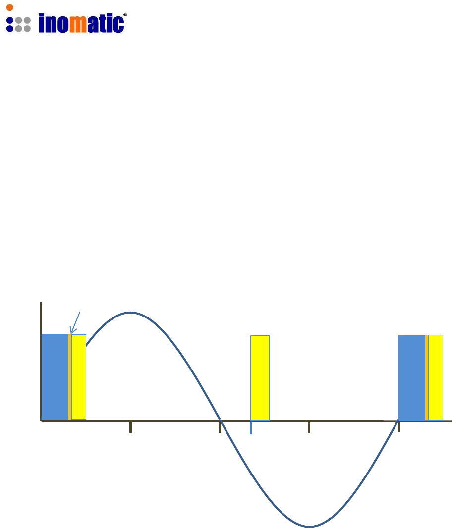
5.1. AM operating principle
The AMTEK AM systems operate on the pulse-listening principle. Using the zero
crossing of the 50Hz mains frequency as a trigger, a short TX pulse of 58 kHz signal is
transmitted and a receiver window is
„o
pened
‟
after the TX pulse has stopped.
If a tag was present within detection range during the TX pulse, the resonance of this
tag will be detected in the Signal (Receiver) window and an alarm will be triggered.
A noise reference window is opened to detect the environmental noise. This signal is
compared with the signal received in the Signal window and allows the software to
properly distinguish a tag signal from a noise signal.
The figure below shows the AM operating principle (at 50Hz, with a default delay of
10μs) during one 50Hz cycle
DEL
TX Pulse
10ms
11.7ms
20ms
TX Pulse 1.6ms or 1.5ms (setting via InfoNet)
LS1 Signal window 500μs
LS2 Reference window 1000μs
DEL Detect delay 100μs
Confidential
AMTEK Version 7.3F 2015-11
Page 26
©Inomatic 2015
TX PULSE
TX PULSE
LS 1
LS 1
LS 2
LS 2
TX PULSE
TX PULSE
LS 1
LS 1
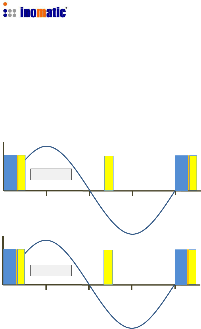
5.2. Synchronization principle
When multiple AM systems are installed in each
other‟s
vicinity,
it‟s
very important to
properly synchronize the TX pulses and receiver windows for all systems involved. If
systems are not properly synchronized they will create false alarms and poor detection.
Keep in mind that AM signals, when compared to other EAS technologies, can “travel”
quite far (up to 100m or more) because of their longer wavelength.
Two AM systems that are properly synchronized
SYSTEM 1
SYSTEM 2
If two or more AMTEK systems are connected to the same main power phase they
would not need to be synchronized by either hardware or software.
Confidential
AMTEK Version 7.3F 2015-11
Page 27
©Inomatic 2015
TX PULSE
TX PULSE
LS 1
LS 1
LS 2
LS 2
TX PULSE
TX PULSE
LS 1
LS 1
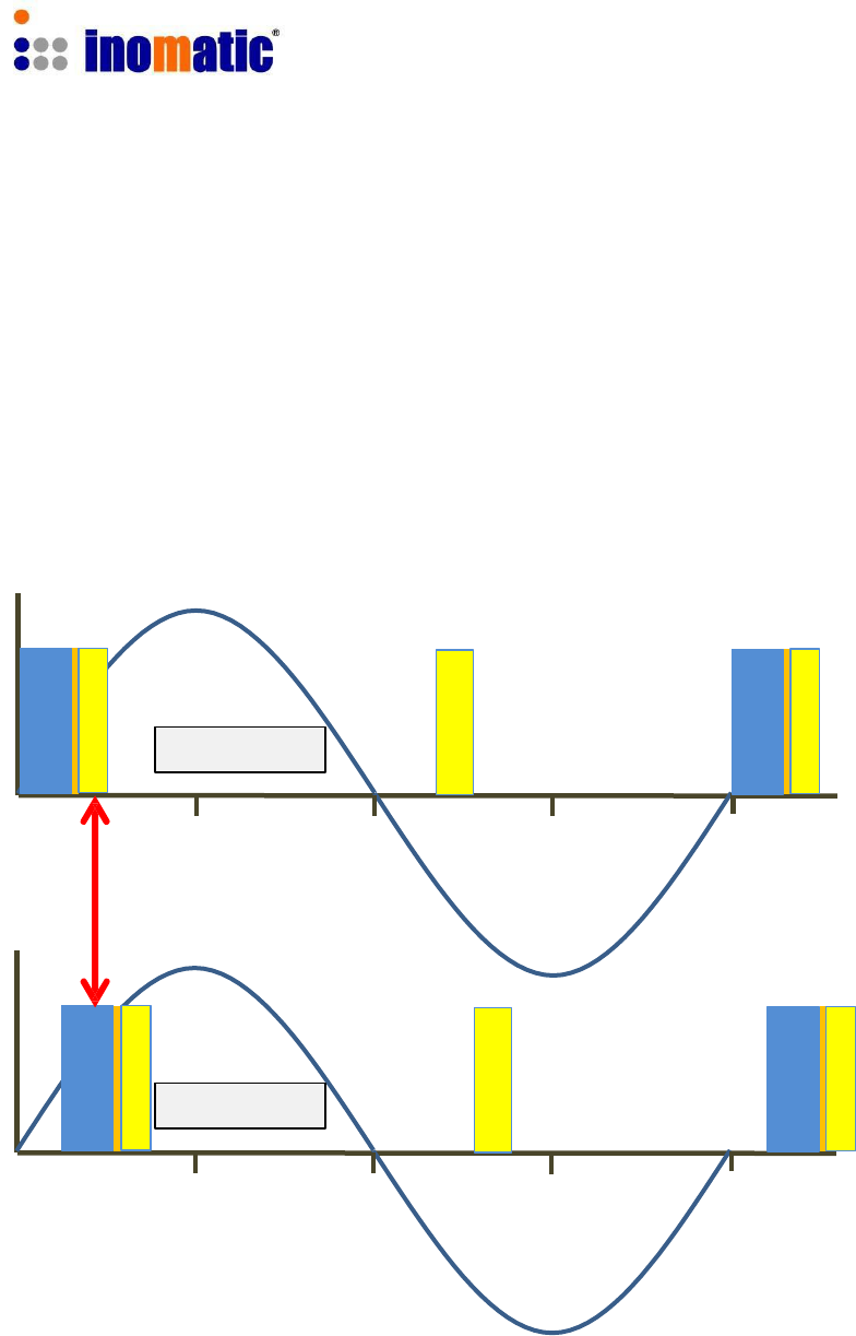
Two AM systems that are NOT synchronized
The TX pulse of system 2 starts later than the TX pulse of system 1, resulting in the fact
that system 1 is receiving the TX pulse of system 2 in its receiver window. This might
create false alarms and poor detection on system 1, whereas system 2 will function
properly as the TX pulse of system 1 is not affecting the receiver window of system 2.
This problem can be solved by making sure that both systems transmit and receive at
the same moment, which can be realized by changing the “Syncron” value time for one
of the two systems using InfoNet software.
SYSTEM 1
SYSTEM 2
Please note that any TX pulse should also not fall into to the Reference window LS 2 as
it would push up the noise level of the system dramatically. The system may not alarm
but the performance will be affected.
Confidential
AMTEK Version 7.3F 2015-11
Page 28
©Inomatic 2015
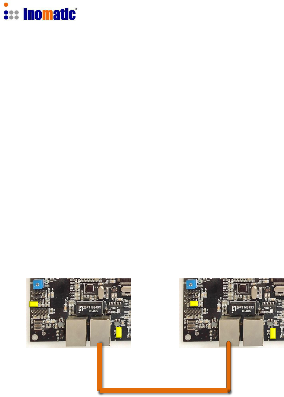
5.3. Hardware Synchronization
Synchronization can be done via software or hardware. The necessary settings for
hardware synchronization are described below. A description of the software-based
synchronization is included in the infoNet Manual.
Hardware synchronization allows a number of X AMTEK systems to be synchronized
with another AM system nearby by synchronizing only the AMTEK “Master antenna”.
The “Slave antennas” will automatically follow the “Master” synchronization.
The LAN ports (LAN1 and LAN2) can be used for connection to the shop LAN and at the
same time for hardware synchronization.
1.) One TX processor board has to be set as Master and the other(s) as Slave.
2.) The hardware synchronization ports (LAN 1 or LAN 2) must be connected with a
shielded LAN cable.
The picture below illustrates the connection and the necessary settings for Master or
Slave operation.
Master TX antenna (1st system) Slave TX antenna (2nd system)
Shielded LAN cable
Confidential
AMTEK Version 7.3F 2015-11
Page 29
©Inomatic 2015
J17 & 18
Sync Bus Termination
All other slaves
Both end of the
sync cable (bus)
1 2 3 J15
Master
Slave
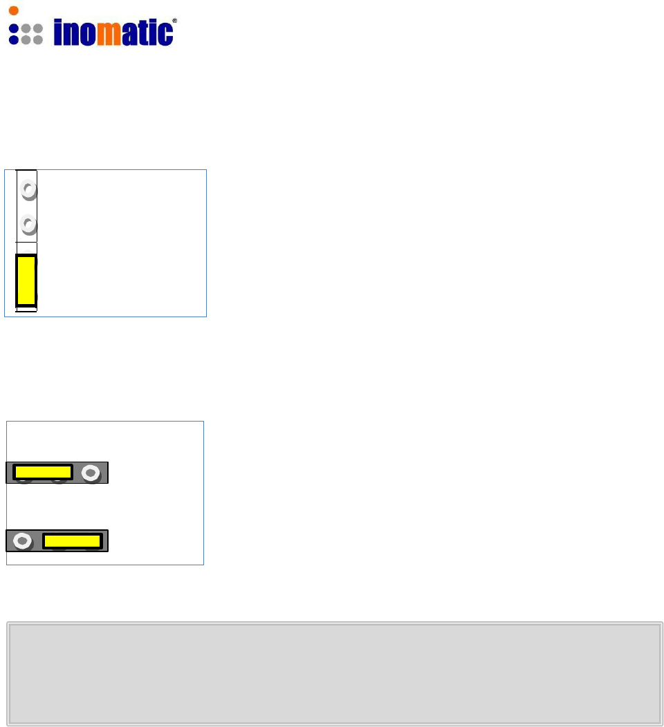
One “Master” can drive several “Slaves”. In order to proper
terminate the Master/Slave Sync bus-cable, the Jumper
J17 or 18 has to be inserted at the beginning of the sync
bus-cable (usually Master antenna) and the end of the bus-
cable (last Slave board).
To set to Master mode (the default mode), put the jumper
J15 in position 2 and 3. For the antenna to operate in Slave
mode put the jumper in position 1 and 2.
When using hardware synchronization, you must set the synchron value to 0
for all “Slave TX” boards by means of the infoNet software (see infoNet Manual).
Shifting the Synchron value for the master TX will automatically shift the
Synchron value of all connected slave antennas.
Please do not turn on the power before the configuration is ready. First switch on
the power supply for the “Slave” antenna and then the power supply to the
“Master” antenna.
Confidential
AMTEK Version 7.3F 2015-11
Page 30
©Inomatic 2015
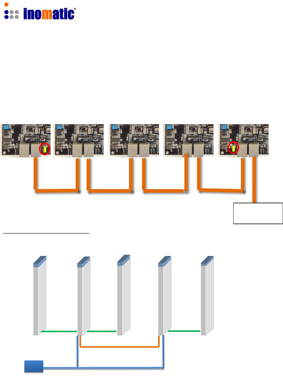
One master can drive several slaves. The way of connection is illustrated below.
Please note the sync cable (bus) has to be terminated to avoid interference.
As such the first board of the sync bus, usually the Master board and the last Slave on
the bus have to be terminated by inserting Jumper J17 or Jumper 18.
Master Slave 1 Other Slaves Last Slave
Installation of 5 Antennas
Shop-LAN
(if required)
RX TX (Master) RX TX (Slave) RX
Hardware Sync/LAN
Dual Power supply V6
The new Dual power supply AMPSS 700V6 allows the connection of two TX antennas.
Confidential
AMTEK Version 7.3F 2015-11
Page 31
©Inomatic 2015
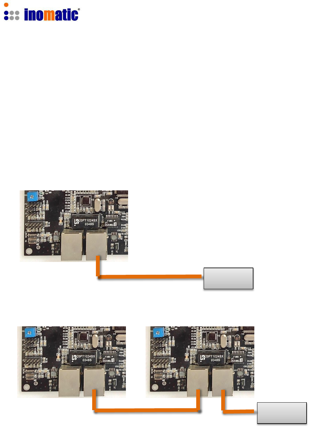
6. LAN CONNECTION
The Pro-Line processor board V7.3 can be connected directly to the shop LAN via a
standard LAN cable. Usually no setting of the shop router is required.
If the board is connected to the LAN, the following features will be available
via infoNet Cloud
a.) Remote service
b.) Remote monitoring
c.) Visitor counter analysis (if equipped with integrated visitor counter module)
For more set-up information please refer to the infoNet V4 software manual
Connection of 1 System (1 Processor board)
Shop LAN
Connection of 2 or more Systems
Shop LAN

Confidential
AMTEK Version 7.3F 2015-11
Page 32
©Inomatic 2015
This device complies with Part 15 of the FCC Rules. Operation is subject to the following two
conditions: (1) this device may not cause harmful interference, and (2) this device must accept any
interference received, including interference that may cause undesired operation.
Changes or modifications not expressly approved by the party responsible for compliance could
void the user's authority to operate the equipment.
NOTE: This equipment has been tested and found to comply with the limits for a Class B digital
device, pursuant to Part 15 of the FCC Rules. These limits are designed to provide reasonable
protection against harmful interference in a residential installation. This equipment generates, uses
instructions, may cause harmful interference to radio communications. However, there is no
guarantee that interference will not occur in a particular installation. If this equipment does cause
harmful interference to radio or television reception, which can be determined by turning the
equipment off and on, the user is encouraged to try to correct the interference by one or more of
the following measures:
-- Reorient or relocate the receiving antenna.
-- Increase the separation between the equipment and receiver.
-- Connect the equipment into an outlet on a circuit different from that to which the receiver is
connected.
-- Consult the dealer or an experienced radio/TV technician for help.