Inomatic MAGIC 8.2MHz EAS System User Manual
Inomatic (Suzhou) Technology Co.,Ltd. 8.2MHz EAS System
Inomatic >
User manual

INOMATIC (S) PTE LTD
10 Toh Guan Road #03-05
Singapore 608838
Tel: 65-67772958
www.inomac.com © Inomac (S) Pte Ltd
Version 2017-04
Specicaons may change without prior noce
1
Operaon Manual RF Standard-Line Mono system (UMB 200S V1.1)
Magic 250/350
Helio 250/300
Universal Mono Standard-Line board UMB 200S Manual
INOMATIC (S) PTE LTD
10 Toh Guan Road #03-05
Singapore 608838
Tel: 65-67772958
www.inomac.com © Inomac (S) Pte Ltd
Version 2017-04
Specicaons may change without prior noce
2
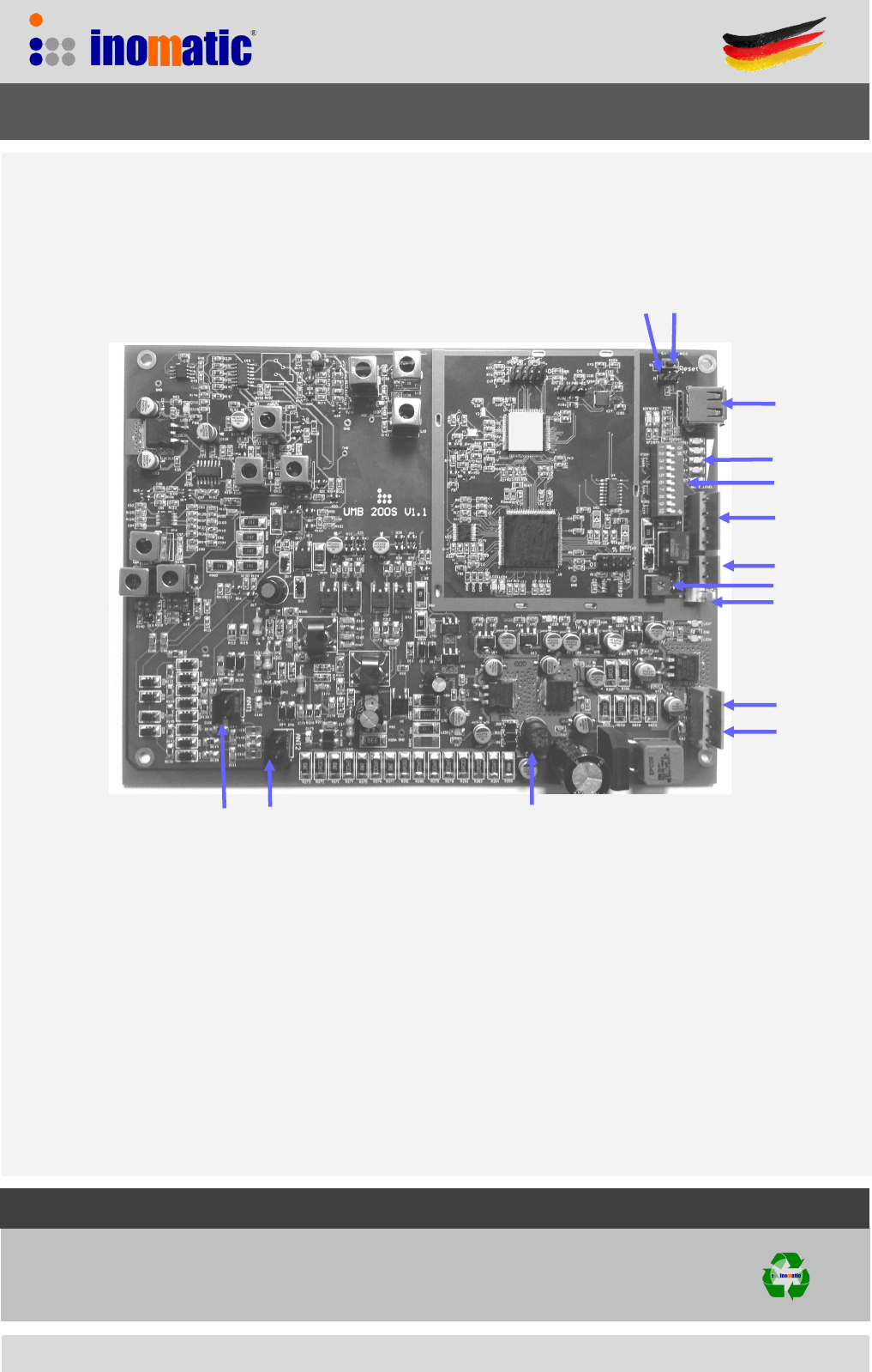
S2
S1
VR2
X5
X1
J1
X3
X4
X9 X8
LED
X1 18VAC power in J1 Operaon/Down- load rmware
X2 18VAC power out F 1 Fuse 1A
X3 Buzzer S2 Selecon switches
X4 Relay output (NO) VR2 Buzzer Volume Control
X5 Alarm /Power LED light (12V DC) S1 Reset processor
X8 Antenna loop 1 (8 loop)
X9 Antenna loop 2 (88 loop or 0 loop)
`
Universal Mono Standard-Line board UMB 200S Manual
UMB 200S
F1
RMS
V1.1
USB
X2

INOMATIC (S) PTE LTD
10 Toh Guan Road #03-05
Singapore 608838
Tel: 65-67772958
www.inomac.com © Inomac (S) Pte Ltd
Version 2017-04
Specicaons may change without prior noce
3
1. Introduction
The Magic/Helio Mono antennas incorporating the UMB 200 Standard-Line Mono electronics is a
DOUBLE TRX-loop single panel system that provides enhanced detection as compared to conven-
tional Mono antennas. Multiple Magic/Helio antennas (UMB 200) can operate at the same time with-
out the need of synchronization.
The system‘s center frequency is 8.2MHz with frequency “hopping” within a certain frequency band
width. This allows good detection of tags even if the center frequency of the tag is not exact 8.2MHz.
Advanced APC (Automatic Parameter Control) and ERC (Enhanced Resonance control ) technology
is applied to process the transmit and receive signal relative to the environmental noise. This not
only benefits the system‘s performance and anti-interference ability but also prevents deactivation of
labels near to the antenna.
The UMB 200S has a USB interface to download new Firmware if becomes available.
The UMB 200S Mono electronics was designed for “PLUG and PLAY” operation
Typical performance
Magic 350 with UMB 200S performance :
4 x 4 label up to 110 cm on each side
Mini square up to 120 cm on each side
R 50 hard tag up to 140cm on each side
The performance depends on the quality of the label/tag and the orientaon of the
label/tag
Universal Mono Standard-Line board UMB 200S Manual
INOMATIC (S) PTE LTD
10 Toh Guan Road #03-05
Singapore 608838
Tel: 65-67772958
www.inomac.com © Inomac (S) Pte Ltd
Version 2017-04
Specicaons may change without prior noce
4
2. Functions/Connections
2.1 Alarm Volume Tuning (VR2)
The sound level of the alarm buzzer can be adjusted by the potentiometer VR2. Turn VR2 clockwise to
increase the volume, counter-clockwise to decrease the volume.
2.2 Down-loading of updated firmware (J1)
The firmware can be updated via the computer. When down-loading the firmware J1 has to be the left
position. After down-loading set J1 to the right position and press S1 to reset the processor. As the
firmware is encrypted please contact our service department for the relevant down-load file.
Jumper 1
2.3 Reset of processor (S1)
Pressing the button S1 will reset the processor
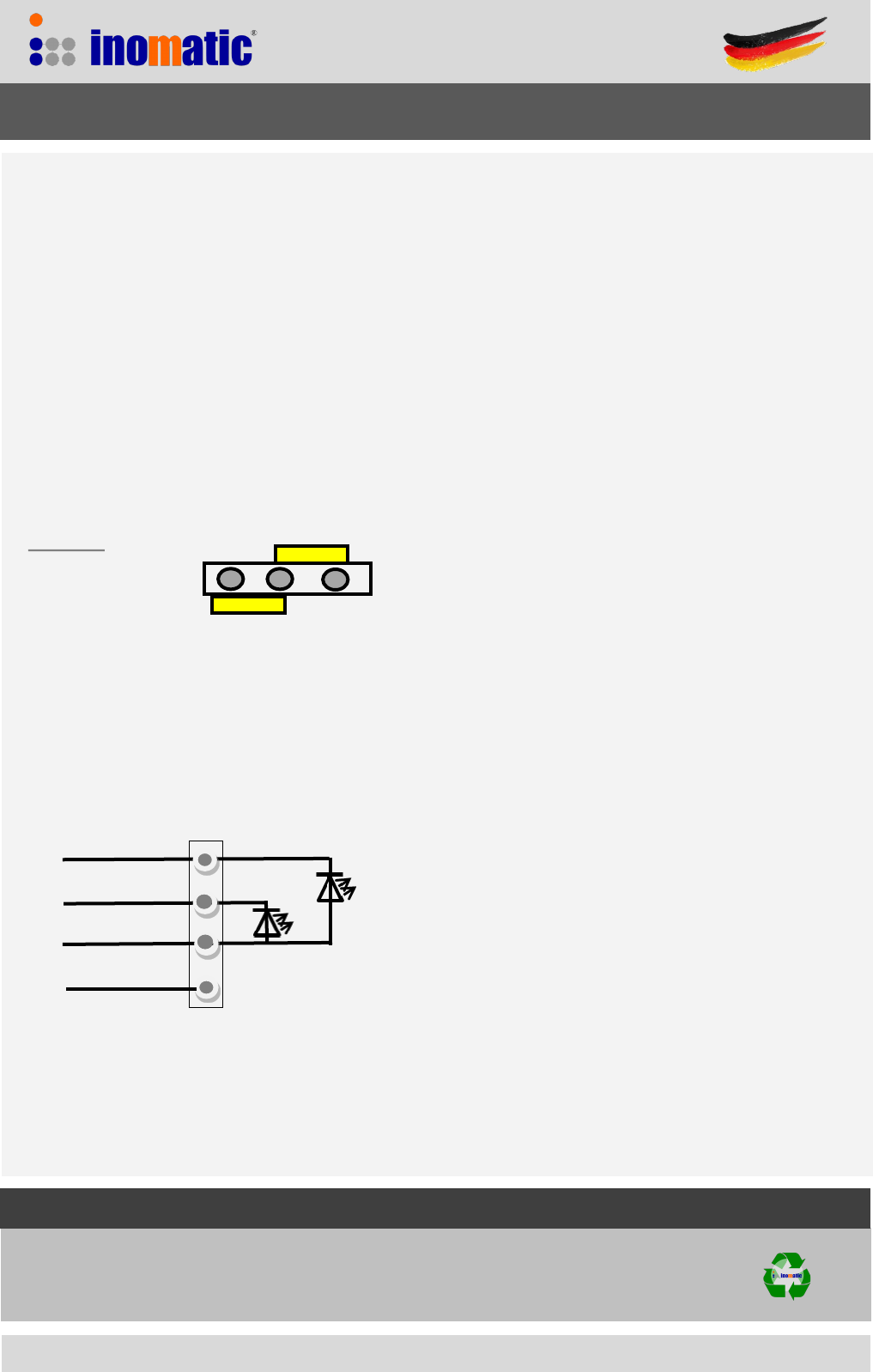
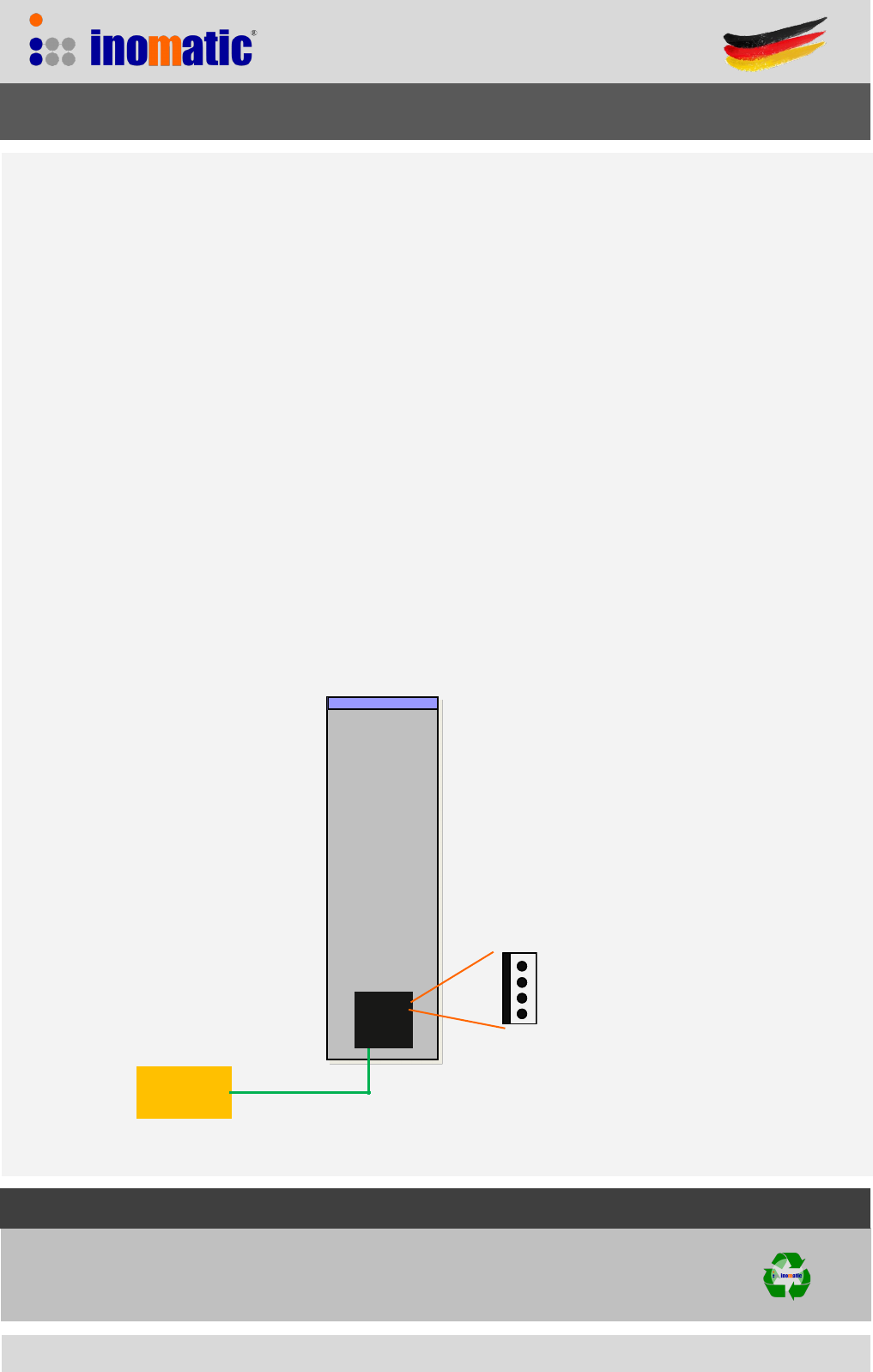
2.4 Power/Alarm light connection X5 (active low)
Note, that non-Inomatic LED modules might influence the board performance and/or resulting
in higher noise.
The maximum current per LED output is 150mA.
Universal Mono Standard-Line board UMB 200S Manual
Normal operaon
Down-load rmware
PW IND LED
GND
PWR +12V
ALR LED Note, that if you like to replace the UMB
100 with the UMB 200 the Alarm LED
module need to be changed as the UMB
100 Alarm output is 24VDC
INOMATIC (S) PTE LTD
10 Toh Guan Road #03-05
Singapore 608838
Tel: 65-67772958
www.inomac.com © Inomac (S) Pte Ltd
Version 2017-04
Specicaons may change without prior noce
5
Universal Mono Standard-Line board UMB 200S Manual
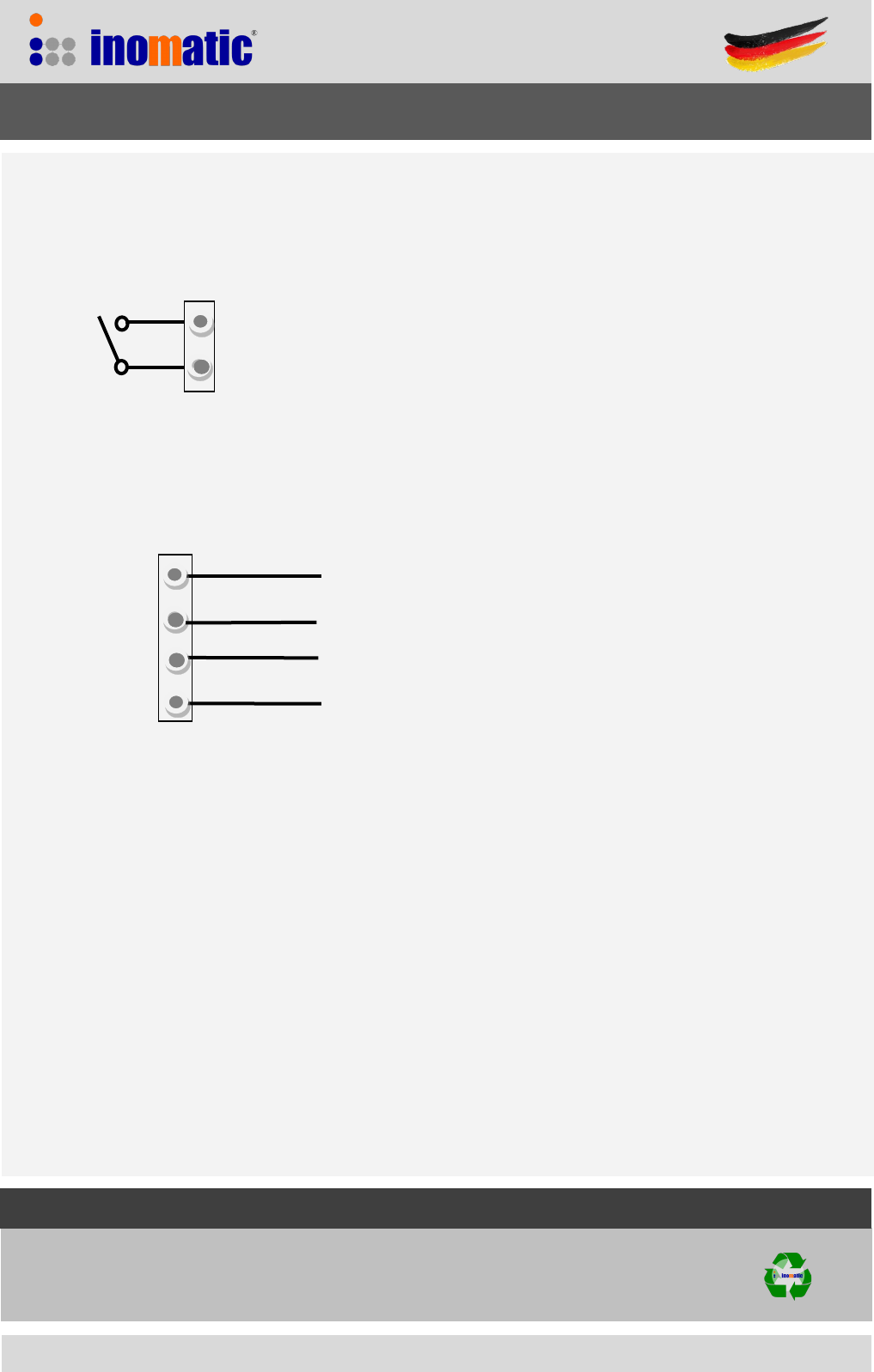
2.5 Relay output (X4)
X4 provides a NO- relay contact output (< 50V DC, 1A). The relay output is activated when the electronics
triggers an alarm.
2.6 Power connection (X1 & X2)
The power supply (18VAC or 24VDC) is connected to X1.
X2 provides an power output of 18VAC or 24VDC depending on the input power supply
2.7 Buzzer connection (X3)
The buzzer (12VDC) is to be connected to X3. Please observe polarity (+/-) of the buzzer.
2.8 USB connector (X7)
The UMB can be connected to the computer via the USB port for firmware update only
2.9 Antenna loop connections (X8 & X9)
The 8 loop of the antenna is connected to X8 (ANT1) and the 88 loop or 0-Loop is connected to X9 (ANT2).
If the 0-loop is not used, both ends of the 0-loop are connected to the ground of the board.
2.10 LEDs
The LEDs L show the environmental noise level of the system. More LEDs —> more noise
IN 18VAC
OUT 18VAC
OUT 18VAC
IN 18VAC
X1
X2
INOMATIC (S) PTE LTD
10 Toh Guan Road #03-05
Singapore 608838
Tel: 65-67772958
www.inomac.com © Inomac (S) Pte Ltd
Version 2017-04
Specicaons may change without prior noce
6
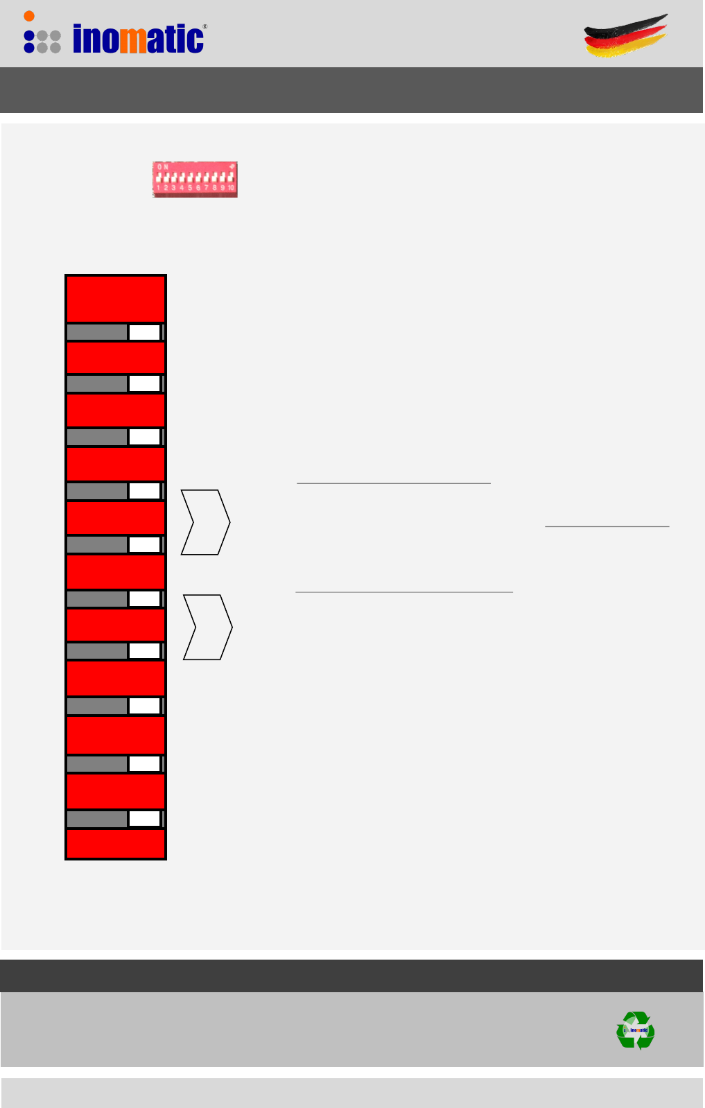
2.11 Switch S2
S2 allows the setting of various functions:
OFF ON
Manual Automac
Filter Wide Filter Narrow
TX OFF TX ON
ERC OFF ERC ON
8 & 88 loop connected O & 8 loop connected
Not in use
Default seng: —> all switches in ON posion
Universal Mono Standard-Line board UMB 200S Manual
OFF ON
Noise 0 Noise 1 Noise 2 Noise 3
ON OFF ON OFF
ON ON OFF OFF
Gain 3 Gain 2 Gain 1 Gain 0
ON OFF ON OFF
ON ON OFF OFF
1
10
Only in Manual mode
INOMATIC (S) PTE LTD
10 Toh Guan Road #03-05
Singapore 608838
Tel: 65-67772958
www.inomac.com © Inomac (S) Pte Ltd
Version 2017-04
Specicaons may change without prior noce
7
3. Installation
When installing RF Mono system (UMB 200S) please ensure that there is no RF Swept-system (TX/RX)
within 10 meters as Swept-systems influence the performance and can cause false alarms.
The swept-system TX generates a continuous 8.2 MHz frequency which negatively affect the noise/
signal ratio and therefore the performance of any Mono antenna. The only alternative is to reduce the
Level of the Mono antenna but this will also reduce the performance of the Mono antenna.
When multiple Mono antennas are installed, power-up and tune the antennas on by one. After all
antennas have been tuned switch on the power to all systems at the same time.
The Mono antennas will synchronize automatically once powered-on. The power supply should be in-
stalled as close as possible to the Mono antenna. If the 18VAC power line is longer as 5 meter an
additional line-filter should be installed.
X1
18VAC /24VDC
1A
Alarm/Power LED connector X5
“Acve low”
ALR -> Alarm light GND, 150mA
IND -> Power light GND, 150mA
PWR -> +12VDC
GND -> Ground
Universal Mono Standard-Line board UMB 200S Manual
INOMATIC (S) PTE LTD
10 Toh Guan Road #03-05
Singapore 608838
Tel: 65-67772958
www.inomac.com © Inomac (S) Pte Ltd
Version 2017-04
Specicaons may change without prior noce
8
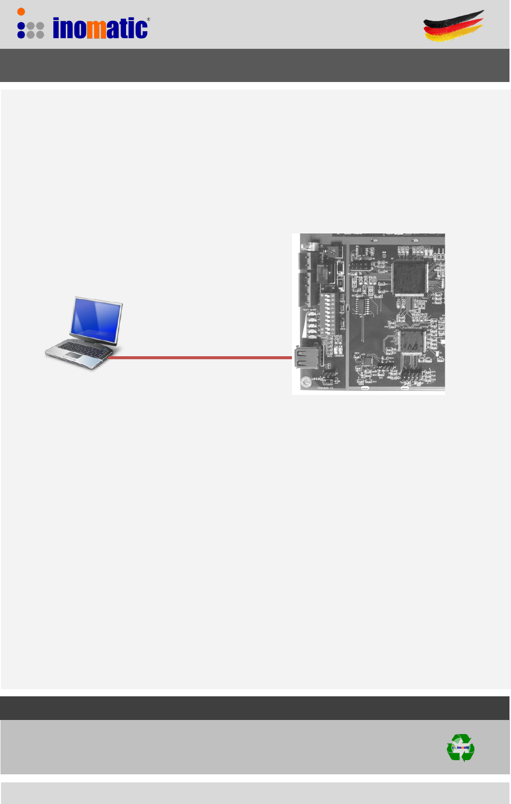
4. Connection to USB
The firmware of the UMB 200S can be updated via the USB port
Computer
Universal Mono Standard-Line board UMB 200S Manual
For Firmware update please contact our service department (service@inomatic.com)
for the firmware update file.
INOMATIC (S) PTE LTD
10 Toh Guan Road #03-05
Singapore 608838
Tel: 65-67772958
www.inomac.com © Inomac (S) Pte Ltd
Version 2017-04
Specicaons may change without prior noce
9
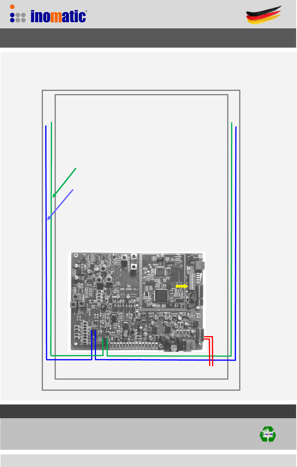
18VAC
X1
X9
X8
O-Loop
8-Loop
Make sure the antenna wires do not run across the
board
Universal Mono Standard-Line board UMB 200S Manual
6. Loop connections
SYSTEM WITH 8 and 0 Loops
Please note that for acrylic antennas, the 8 and 88 loop
have to be connected jointly to X8.
S2-9 ON
Default wiring
If the switch S2-9 is
OFF, the perfor-
mance of the system
increases but it might
be more noise
sensitive.
INOMATIC (S) PTE LTD
10 Toh Guan Road #03-05
Singapore 608838
Tel: 65-67772958
www.inomac.com © Inomac (S) Pte Ltd
Version 2017-04
Specicaons may change without prior noce
10
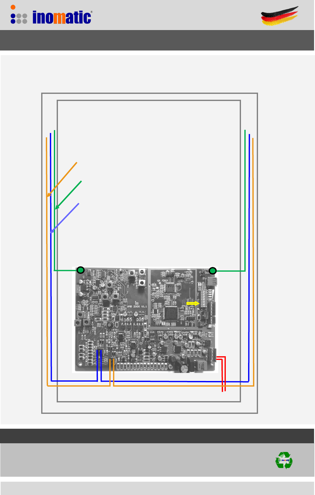
18VAC
X1
X9
X8
O-Loop
8-Loop
Make sure the antenna wires do not run across the
board
Universal Mono Standard-Line board UMB 200S Manual
6. Loop connections
SYSTEM WITH 8 and 88 Loops
88-Loop
S2-9 OFF
INOMATIC (S) PTE LTD
10 Toh Guan Road #03-05
Singapore 608838
Tel: 65-67772958
www.inomac.com © Inomac (S) Pte Ltd
Version 2017-04
Specicaons may change without prior noce
11
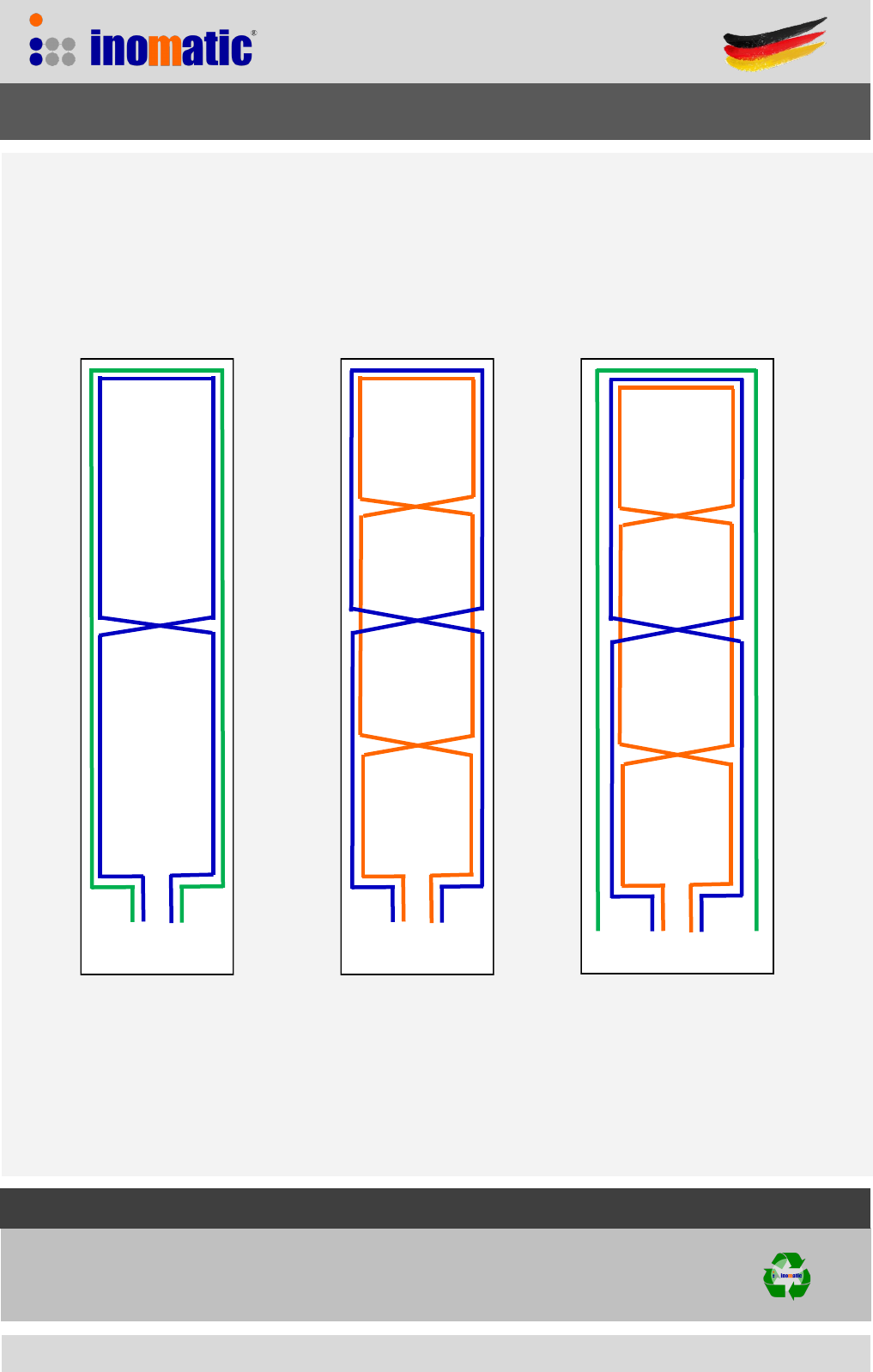
7. Antenna wiring
— TRX1 Connect to X9 (3,4)
— TRX2 Connect to X8 (1,2)
B.) High Noise environment A.) Default wiring of Mono
antenna using UMB 200S
— TRX1 Connect to X9 (0,0)
— TRX2 Connect to X8 (1,2)
If the 0 loop is not used, connect both end of the loop to the GND of the board
0 1 2 0 1 3 4 2 0 1 3 4 2 0
Antenna standard wiring includes 3
loops , 0 loop (0,0), 8 Loop (1,2) and 88
loop (3,4)
Universal Mono Standard-Line board UMB 200S Manual

INOMATIC (S) PTE LTD
10 Toh Guan Road #03-05
Singapore 608838
Tel: 65-67772958
www.inomac.com © Inomac (S) Pte Ltd
Version 2017-04
Specicaons may change without prior noce
12
8. REGULATORY COMPLIANCE
This equipment complies with European Community regulatory rules for Radio Frequency
emissions. It has been awarded with the CE mark.
The CE mark is the official marking required by the European Community for all Electric and
Electronic equipment that will be sold or put into service for the first time, anywhere in the
European community. It proves to the buyer and user that this product meets all essential
safety and environmental requirements as they are defined in the “European Directives”.
Universal Mono Standard-Line board UMB 200S Manual
This device complies with Part 15 of the FCC rules. Operation is subject to the following two
conditions: 1) this device may not cause harmful interference, and 2) this device must accept any
interference received, including interference that may cause undesired operation.
Changes or modifications not expressly approved by the party responsible for compliance could
void the user's authority to operate the equipment.