Inovonics Wireless 3B63MH3 Headset Intercom User Manual Operating Instructions
Inovonics Wireless Corporation Headset Intercom Operating Instructions
Operating Instructions
Headset Intercom System
Model C1060
Operating Instructions

Model C1060 Table of Contents
3M 2001 February i
Intended Use.....................................................................................................................................iii
FCC Information .............................................................................................................................iii
System Description ..........................................................................................................................1
Introduction ...................................................................................................................................1
System Configurations....................................................................................................................1
Single–Lane Standard Communication System...........................................................................1
Single–Lane Duplex Communication System.............................................................................1
Dual–Lane Standard Communication System.............................................................................1
Dual–Lane Duplex Communication System...............................................................................1
Cross–Lane Communication System..........................................................................................1
System Components .......................................................................................................................2
Base Station.............................................................................................................................2
Headset....................................................................................................................................2
Programming Station................................................................................................................3
Battery Charger........................................................................................................................3
Controls and Indicator....................................................................................................................4
Base Station...................................................................................................................................4
Headset..........................................................................................................................................5
Battery Chargers.............................................................................................................................7
Headset Preparation........................................................................................................................8
Adjusting Headband Size..........................................................................................................8
Positioning the Ear Pad and Microphone....................................................................................8
Operation..........................................................................................................................................9
System Startup ...............................................................................................................................9
Turning On the Base Station......................................................................................................9
Turning On the Headset............................................................................................................9
Operating Modes............................................................................................................................9
Standby Mode..........................................................................................................................9
Talk/Listen Mode .....................................................................................................................9
Single–Lane Standard or Duplex Communication Systems....................................................9
Dual–Lane Standard or Duplex Communication Systems......................................................9
Cross–Lane Communication Systems ..................................................................................9

Table of Contents Model C1060
3M 2001 February
ii
Talk Lock Mode (“Hands Free”) ...............................................................................................10
Page Mode...............................................................................................................................11
Page Monitor Mode..................................................................................................................11
Special Considerations....................................................................................................................12
Maintenance.....................................................................................................................................13
Headset..........................................................................................................................................13
Replacing the Battery................................................................................................................13
Replacing the Ear and Headband Pads .......................................................................................14
Battery Charger..............................................................................................................................15
Location...................................................................................................................................15
Cleaning the Contacts ...............................................................................................................15
Batteries ........................................................................................................................................15
Care, Handling, and Storage......................................................................................................15
Low Battery Tone.....................................................................................................................15
Charging Batteries....................................................................................................................15
Disposing of Batteries...............................................................................................................16
Making Sure Batteries are Ready for Use...................................................................................16
Important Information about C1060 Rechargeable Batteries........................................................16
Special Instructions for System Manager......................................................................................17
Programming the Headset for Cross–Lane Operation.......................................................................17
Reprogramming........................................................................................................................17
Enabling/Disabling the Talk Lock Feature .......................................................................................18
Changing Channels if Interference is Encountered............................................................................18
Changing the Day/Night Switch Setting...........................................................................................21
Adjusting the Monitor Speaker Volume ...........................................................................................22
Troubleshooting ...............................................................................................................................23
Introduction ...................................................................................................................................23
System Troubleshooting..................................................................................................................23
Battery and Battery Charger Troubleshooting...................................................................................26
Service ..........................................................................................................................................27

Model C1060 Important Information
3M 2001 February iii
Intended Use
The 3M Headset Intercom System, Model C1060, is designed to provide 2–way
radio–frequency audio communication in quick service drive–through
restaurants and convenience stores.
Misuse of the Model C1060 could result in poor performance and/or undesired
operation.
FCC Information
This device complies with part 15 of the FCC Rules. Operation is subject to the
following two conditions: (1) This device may not cause harmful interference,
and (2) this device must accept any interference received, including interference
that may cause undesired operation.
Changes or modifications not expressly approved by the party responsible for
compliance could void the user’s authority to operate the equipment.

Important Information Model C1060
3M 2001 February
iv
(Blank Page)

Model C1060 System Description
3M 2001 February 1
The 3M Model C1060 Headset Intercom System is a wireless intercom system
designed for high reliability, compactness, and ease of service.
The system can be programmed to operate on any one of 16 different channels
to provide high–quality audio performance and reduce the possibility of
interference between neighboring wireless systems.
The system can be configured in one of five ways depending on the number of
menu signs (lanes) at the facility and the type of communication desired.
The single–lane standard communication system provides standard
communication (talk or listen) for facilities that have one menu sign.
The system consists of one base station and one or more headsets and battery
chargers.
The single–lane duplex communication system provides duplex communication
(simultaneous talk and listen) for facilities that have one menu sign.
The system consists of one base station and one or more headsets and battery
chargers.
The dual–lane standard communication system provides standard
communication (talk or listen) for facilities that have two menu signs.
The system consists of two independent systems - one dedicated to menu sign 1
and the other dedicated to menu sign 2. The headsets are programmed to work
with one system or the other and are labeled accordingly (1 or 2).
The dual–lane duplex communication system provides duplex communication
(simultaneous talk and listen) for facilities that have two menu signs.
The system consists of two independent systems - one dedicated to menu sign 1
and the other dedicated to menu sign 2. The headsets are programmed to work
with one system or the other and are labeled accordingly (1 or 2).
The cross–lane communication system provides duplex communication
(simultaneous talk and listen) for facilities that have two menu signs.
The system consists of two duplex systems that are connected to a cross–lane
module. The headsets are programmed for either lane 1 or lane 2.
During off–peak hours, the cross–lane module can be turned ON to link the two
systems and enable one operator to simultaneously talk and listen to customers
at menu sign 1 or menu sign 2 or with other headset operators.
During peak hours, the cross–lane module can be turned OFF to separate the
systems and enable menu sign 1 operators to talk to customers at menu sign 1,
and menu sign 2 operators to talk to customers at menu sign 2.
Introduction
System
Configurations
Single-Lane Standard
Communication
S
y
stem
Dual-Lane Standard
Communication
S
y
stem
Dual-Lane Duplex
Communication
S
y
stem
Single-Lane Duplex
Communication
S
y
stem
Cross-Lane
Communication
S
y
stem
System Description Model C1060
3M 2001 February
2
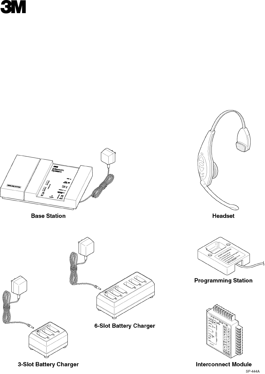
The number of system components and the procedures necessary to operate
them vary depending on the system configuration. However, four components
are common to all system configurations.
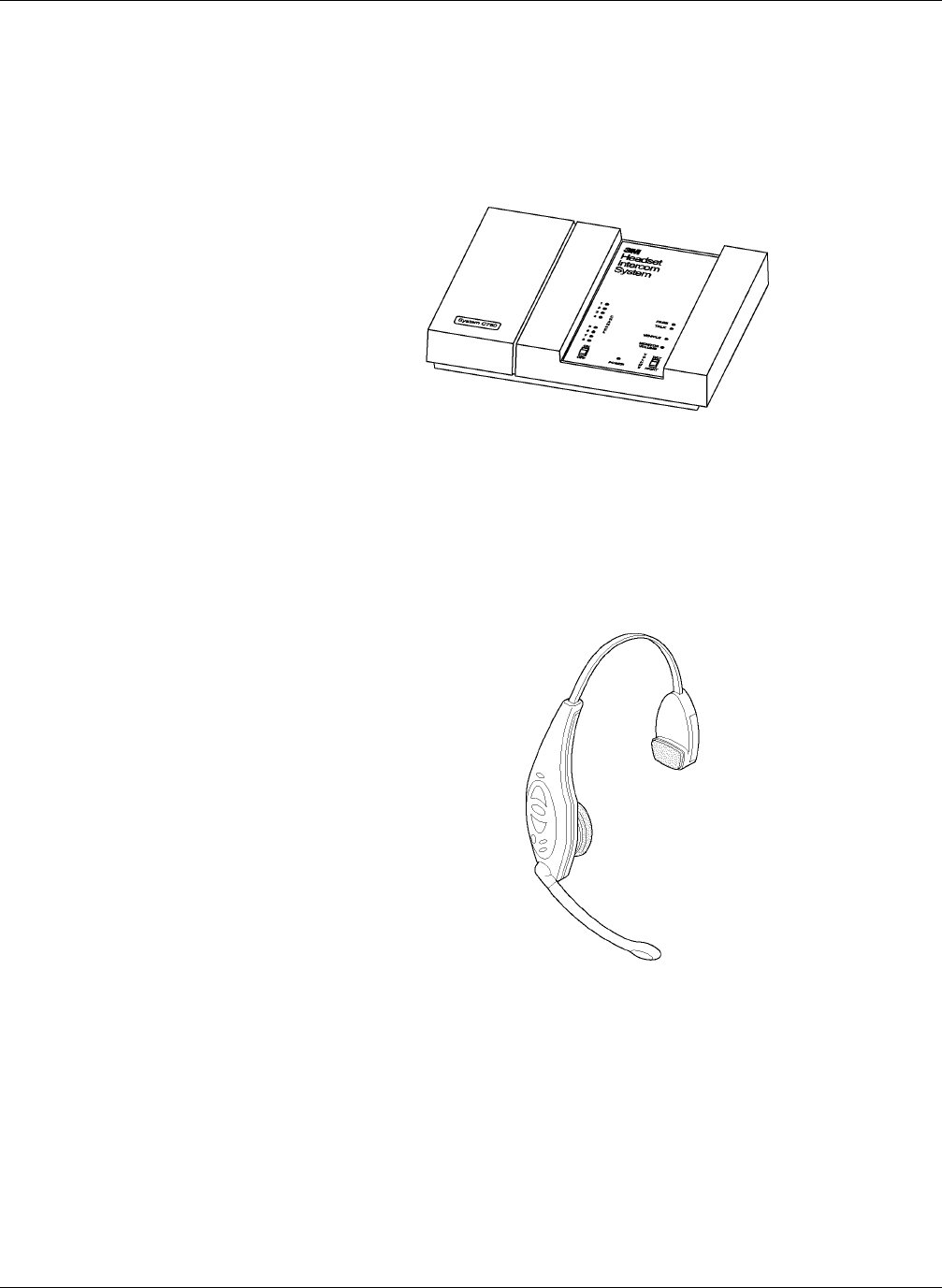
The base station is the interface between the customer at the menu sign and the
headset worn by the operator. See Figure 1.
Figure 1. Base Station
The headset is a wireless, battery–powered, two–way radio used by the operator
to communicate with menu sign customers and with other store personnel who
are wearing headsets.
Headsets feature a light–weight design to provide for comfort. The headset pads
can be easily replaced. See Figure 2.
Figure 2. Headset
Systems
Components
Base Station
Headset
Model C1060 System Description
3M 2001 February 3
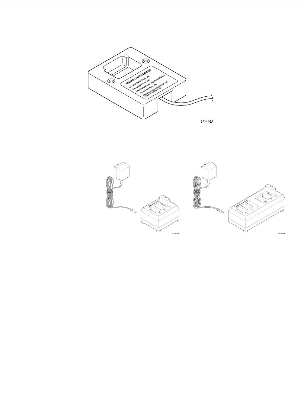
The programming station is used to program C960 and C1060 headsets to the
same channel as the base station. Infrared light is used to transfer program data
to the C1060 headset and a separate jack is provided for the C960 headset
programming cable. See Figure 3.
Figure 3. Programming Station
The battery charger charges headset batteries in approximately 1.5 to 2 hours.
The charger is available in 3–slot and 6–slot versions. See Figure 4.
Figure 4. 3–Slot and 6–Slot Battery Chargers
Battery Charger
Programming Station
Controls and Indicators Model C1060
3M 2001 February
4
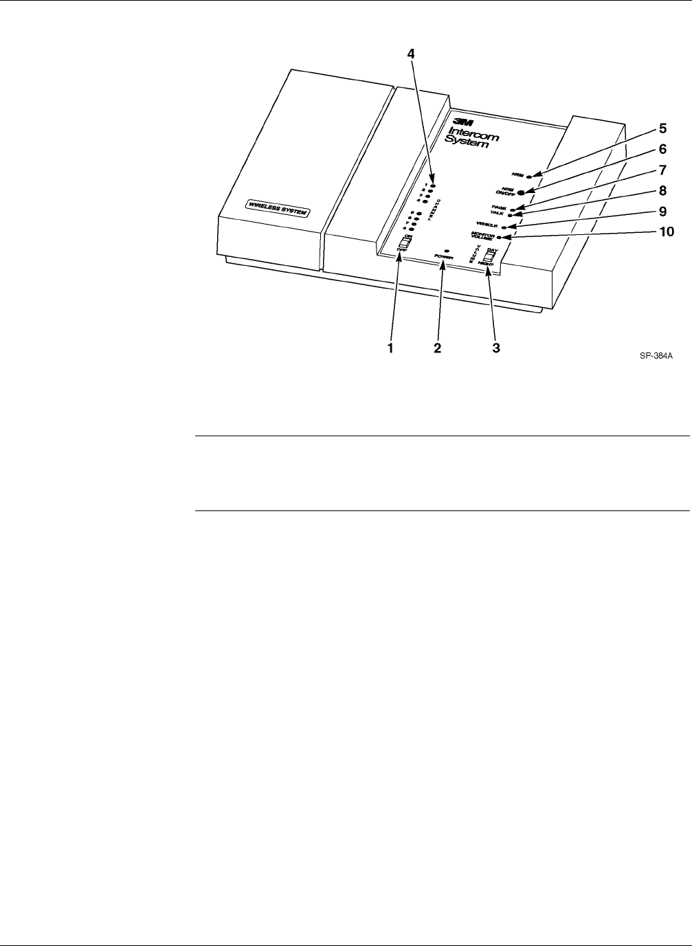
The base station controls and indicators are shown below.
Figure 5. Base Station Controls and Indicators
The ON/OFF switch controls power to the base station.
This indicator lights when the ON/OFF switch is in the ON position.
! Note
If for some reason the C1060 headset system does not operate and the system
includes an optional wired backup system, turn off the C1060 Base Station to
enable the backup system.
With the switch in the DAY position, the volume of the menu sign speaker is
increased for daytime operation. With the switch in the NIGHT position, the
volume of the menu sign speaker is decreased for nighttime operation. (Sound
travels further and more efficiently at night.)
These indicators light to show which of the 8 channels is selected.
This indicator blinks when the Noise Reduction Module is switched on.
This button turns the optional Noise Reduction Module on or off.
This indicator lights when headset Page communications occur.
This indicator lights when headset–to–menu sign “Talk” communications occur.
This indicator lights when a vehicle is detected at the menu sign.
This access hole allows for adjusting the volume of the optional monitor
speaker.
Base Station
1 ON/OFF Switch
2POWER
Indicator
3VOLUME
DAY/NIGHT
Switch
4
C
hannel Indicators
5
N
RM Indicator
6 NRM On/Off
Button
7 Page Indicator
8 Talk Indicator
9 Vehicle Indicator
10 Monitor Volume
Access
Model C1060 Controls and Indicators
3M 2001 February 5
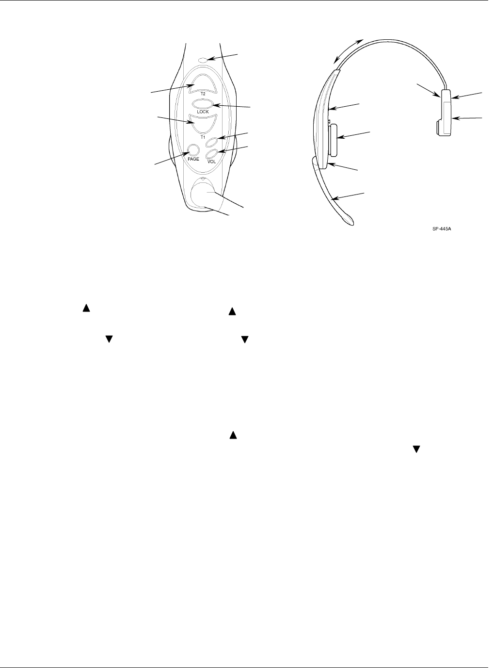
The headset controls are shown below.
1
2
3
4
5
6
7
8
9
10
11
13
12
14
15
Figure 6. Headset Controls
Press the switch once to turn on the headset, and press it again (when the
headset is on) to turn off the headset
Press the volume up control to increase the volume in the headset earpiece.
Press the volume down control to decrease the volume.
When either volume control is pressed, the headset emits a short tone to indicate
the new volume level. There are multiple volume levels from minimum to
maximum.
If the headset volume is at its maximum level, a low, continuous tone sounds
when the volume up control is pressed. A low, continuous tone also occurs
when the volume reaches minimum level and the volume down control is
pressed.
When the headset is turned on, headset volume automatically returns to the mid-
range level. Note that even when set to its lowest level, headset volume is not
turned completely off.
Press and hold the T1 (Talk Lane 1) switch to talk to the customer at the menu
sign in lane 1. Release the switch to listen.
1 ON / OFF Switch
Headset
2 Volume UP
Control
3 Volume DOWN
Control
4 T1 (Talk Lane 1)
S
witch

Controls and Indicators Model C1060
3M 2001 February
6
For dual–lane systems, press and hold the T2 (Talk Lane 2) switch to talk to the
customer at the menu sign in lane 2. Release the switch to listen.
For single–lane systems, T2 can also be used to talk to lane 1.
Press and hold the Page switch to talk to internal personnel without being heard
by the customer at the menu sign. Release the switch to listen. (With the switch
released, you can hear both menu sign customers and internal paging.)
For duplex systems, press the talk lock switch once to talk and listen to the
customer. This enables hands–free operation.
Push the battery release up and hold it there while removing the battery from the
headset housing.
This rechargeable battery provides power to the headset.
This window accepts the Infrared programming signals from the programming
station to allow the headset to be programmed to the same channel as the base
station.
The microphone sends the headset operator’s voice to the menu sign or other
headset operators while eliminating unwanted background noise.
The earphone is a speaker that broadcasts the voice from the customer at the
menu sign or from other headset operators. The replaceable earpad covers the
earphone and cushions the operator’s ear to provide comfort. Earpad angle
adjustment is required
The headband adjustment slide is used to increase or decrease the size of the
headband..
See Figure 11 for battery replacement . A 1/8 inch thick foam rubber pad
cushions the side of the operator’s head for comfort.
Indicates operating status of the headset as follows:
– glows green when power is on
– glows red when in Talk Lock mode
flashes to indicate successful programming
5 T2 (Talk Lane 2)
Switch
6 Page Switch
7 Talk Lock Switch
(
Hands Free
)
8 Battery Release
9 Battery
10 Headset
Programming
Window
11 Microphone
12 Earphone/Earpad
14 Battery Side
13 Headband
Adjustment Slide
15 Indicator LED
Model C1060 Controls and Indicators
3M 2001 February 7
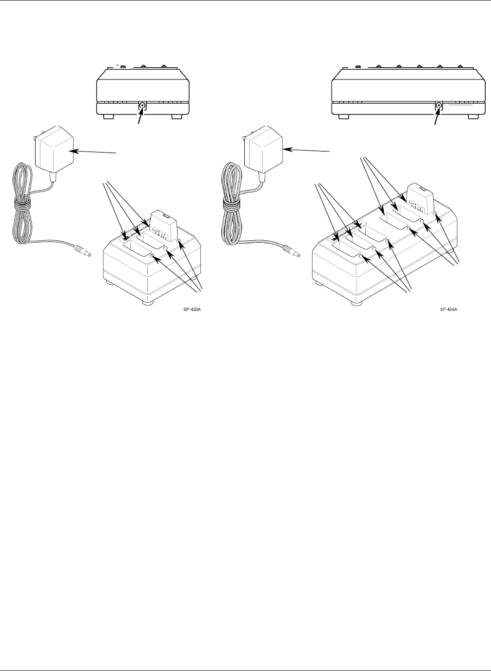
The 3–slot and 6–slot battery charger controls are shown below.
(Rear View) (Rear View)
1
2
4
1
1
2
2
4
The charging slots hold batteries during the recharging cycle.
The charging status indicators light RED or GREEN to indicate charging status:
RED indicates the battery is being charged.
GREEN to indicate the battery is fully charged.
This jack accepts the plug from the power supply cord.
The power supply provides power to the battery charger.
Battery Chargers
1 Charging Slots
2 Charging Status
Indicators
4 Power Supply
33
Operation Model C1060
3M 2001 February
8
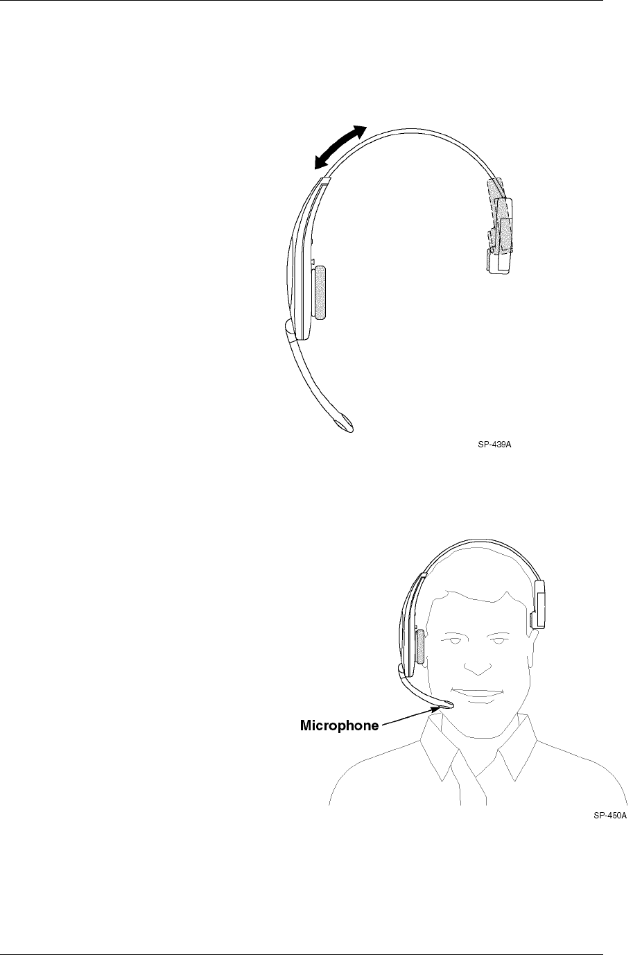
Adjust the size of the headband until the ear pad rests against one
ear and the battery-side pad rests just above the other ear.
• Slide the headband out of the headset to make it larger.
• Push the headband into the headset to make it smaller.
-
Figure 7. Headband Size
Rotate the microphone boom up or down so that its tip is in line
with the corner of your mouth. Do not bend the rubber
microphone boom. See Figure 8.
Figure 8.
Adjusting Headband
Size
Positioning the Ear
Pad and Microphone