Inovonics Wireless 3B6AVBLP ANALOG VOICE BELTPACK User Manual Installation Instructions
Inovonics Wireless Corporation ANALOG VOICE BELTPACK Installation Instructions
Users Manual

1
QSR Performance Solutions Drive Thru System - Installation Instructions
What Is Included
1 — Base Station w/ 13.5 VDC power adaptor
1 — Programming station w/ 18” cable
1 — Microphone for inbound audio
1 — Speaker for outbound audio
1 Lot — Acoustic foam for speaker post
Varies Per Order — Belt-packs w/ pouch
1 — Battery per Belt-Pack (w/1 additional battery when 4 or more belt-packs are ordered)
Varies Per Order — Headsets (1 per belt-pack)
1 — Battery charger w/ 5 VDC power adaptor
What Is Not Included
• Cable to connect Base to speaker post equipment (3 separately jacketed, shielded, twisted pairs,
minimum 20 gauge stranded)
• Vehicle detection loop
• Optional grill speaker (8 ohms)
• Speaker post
• Conduit from inside restaurant to speaker post
• Miscellaneous hardware
• Tools
Installation Steps
1. Begin charging batteries prior to installing system
2. Determine best location for Base
• Needs electrical outlet (power adaptor has 6 foot cable)
• Maintain 3 feet clearance from large metal objects and electrical or electronic equipment
• Relative close proximity to drive thru booth(s) but avoid installing where base cannot be ser-
viced without interrupting normal business operations
• Be mindful of where conduit to speaker post terminates inside
• Programming station connects to base with 18” cable and needs to be at a height and location
that is accessible to restaurant employees
3. Install cabling from speaker post to Base location. 3 individually shielded, jacketed, twisted pairs, mini-
mum 20 gauge stranded.
4. Mount Base and connect cables (keep power cable and transformer at least 6 inches from left side of
Base)
5. Mount programming station within 18” of Base, and at an accessible height and connect cable
6. Mount vehicle detector and connect to Base, and to cable feeding to loop at speaker post
7. Install speaker and microphone in speaker post and connect cables, including connection to vehicle
detector loop. Solder all splices.
• IMPORTANT! Speaker and microphone inside of speaker post MUST be acoustically and me-
chanically isolated from each other AND the speaker post with foam rubber or an acoustic
dampening material to insure quality audio performance.
• In a typical speaker post the microphone would be mounted in the top section, closer to the
person placing the order. The speaker should be at least 2 feet away from the microphone,
typically mounted lower.
2
Installation Steps — cont.
8. Make sure jumpers in Base are configured to match your installation (see Base Station Controls dia-
gram)
• J1 & J2 — Separate speaker & mic or one device serving as both
• J4 — Detection type: closure or pulse
• J5 — Full-duplex or Standard (half-duplex)
• J6 — Full-duplex click suppression
9. Turn on power to base
10. Insert batteries in belt-packs and program per instructions on programming station
11. Connect headsets to belt-packs and test range, reception, audio quality, and volume
12. Adjust volume levels as needed
13. Test vehicle detection
14. Train restaurant employees and manager
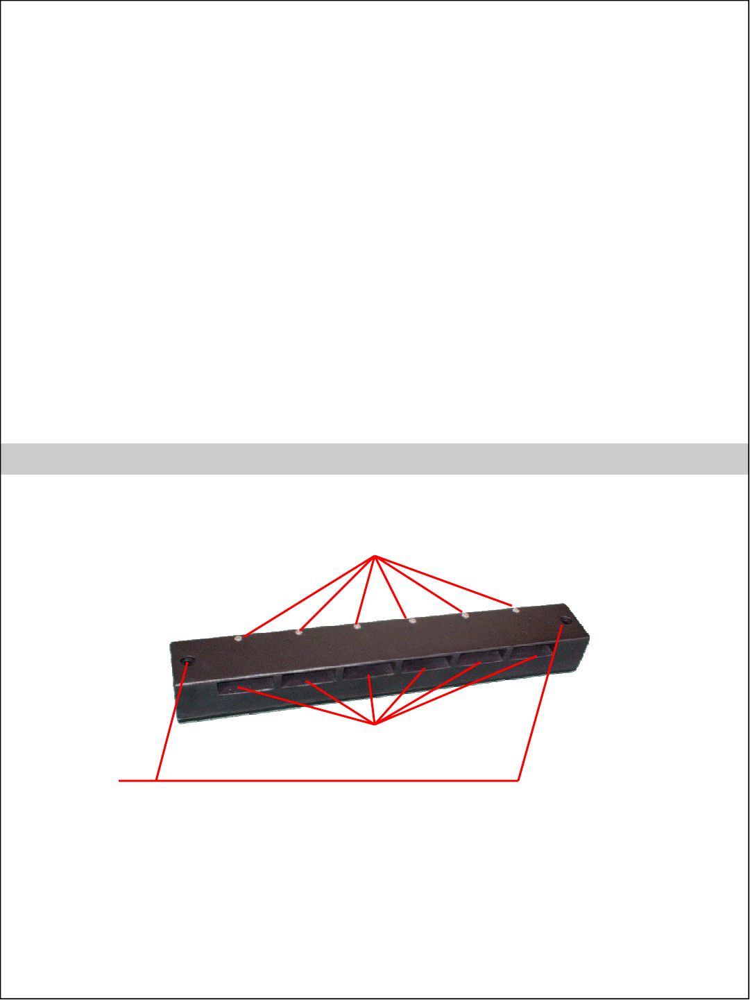
QSR Drive Thru Solutions - Batteries & Charger
Charging Indicators — Will light red
when battery is charging and change
to green when battery is charged
Charging Ports for
Batteries
Holes for Wall
Mount Screws
NOTES:
• Batteries are Lithium-Ion
• Batteries require about 3 hours to charge
• Batteries will hold a charge for about 8 to 10 hours during normal use
• When the battery voltage becomes too low, a short warble tone, occurring at five–second
intervals is heard in the headset. After 2 minutes the headset will shut off.
• Batteries should be removed from belt-pack and stored in charger when not being used.
3
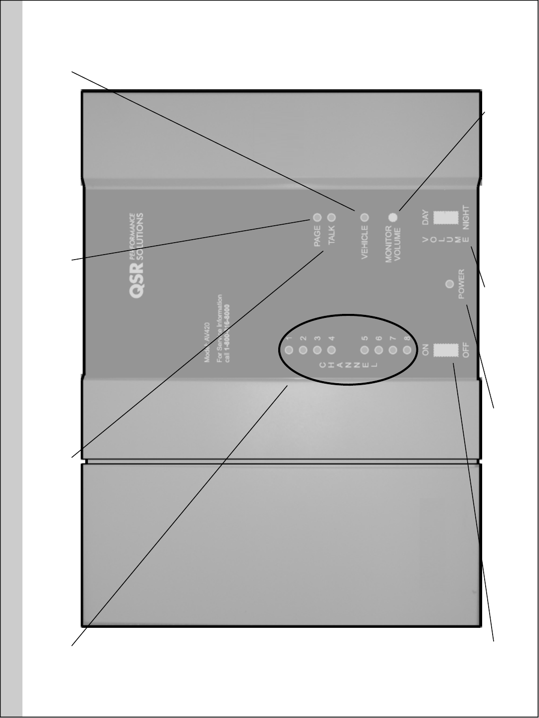
QSR Performance Solutions - Base Station Front Cover Indicators & Controls
Channel Indicators
Indicates which one of the eight
channel frequencies is being used
Page Indicator
Lights when the Page button
is pressed on a belt-pack
Talk Indicator
Lights when the Talk button
is pressed on a belt-pack
Power Switch
Used to turn power to base off &
on. Turn off to enable optional
wired backup if one is installed.
Power Indicator
Lights when power is
applied to base.
Day / Night Volume Switch
Day position enables DAY outgoing
volume control. Night position enables
NIGHT outgoing volume control.
Grill Monitor Volume
Adjusts the volume of
the optional grill speaker
Vehicle Indicator
Lights when vehicle is
detected at speaker post
4
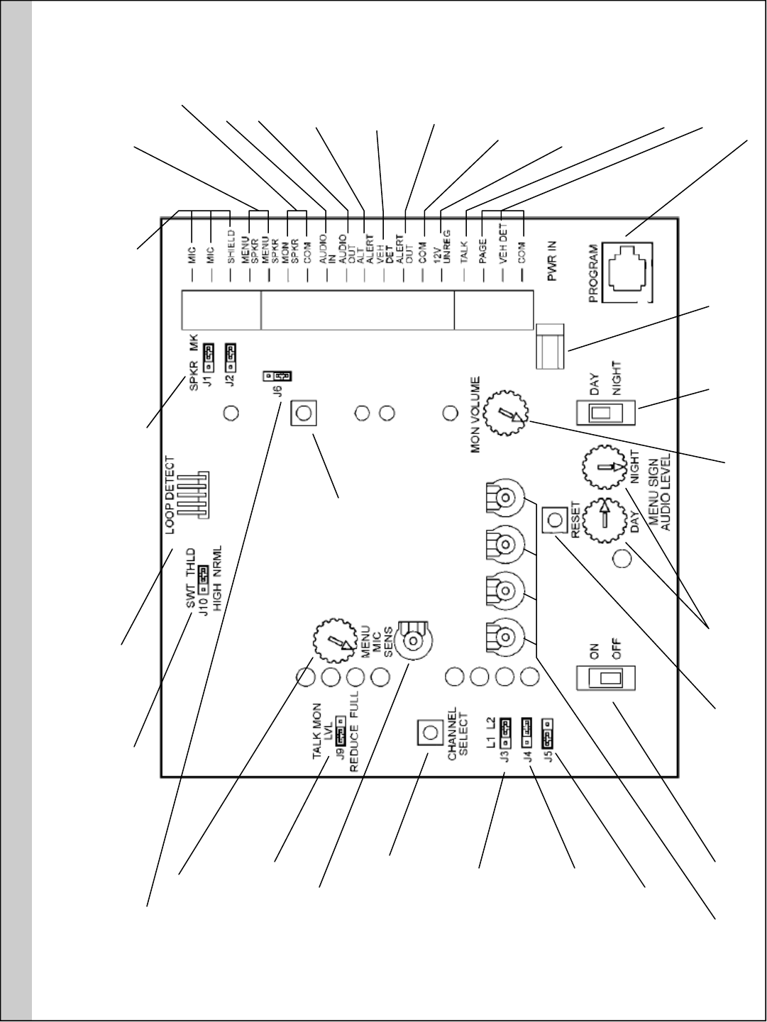
QSR Performance Solutions - Base Station Controls
Must jump upper pins
when system is half-
duplex. Jump lower pins to
eliminate clicking when
TALK button is pressed
with full-duplex system
Set to HIGH if
inbound level in
headsets is low
when used in
TALK-LOCK
Connects to
optional inter-
nal vehicle
detect board
When a single device is used
as the speaker and mic at the
menu board, jump pins 1 & 2
on J1 and J2. Jump pins 2 & 3
on J1 and J2 when a separate
speaker and mic are used.
Connects to micro-
phone at menu-board.
Should have a 1500
ohm resistor installed
in series on both legs
of mic line.
Connects to menu-
board speaker. When
using 1 device as a
speaker and mic, use
this connection.
To grill speaker
Used with greeters
Not normally used
Connects to
cross-lane module
in 2 lane system
Connects to one leg
of vehicle detector
contact closure
Connects to cross-
lane module in 2
lane system
Connects to greeters
and cross-lane modules
To other leg of contact
closure on vehicle de-
tector and supplies
power to interconnect
module relay
Used with greeters
Not normally used
To headset
programming station
To 13.5 VDC
power transformer
Determines if
outgoing audio is
Day or Night level
Grill speaker
master volume
Outgoing audio
to menu-board
speaker
Used to allow base
to recognize new
jumper and channels
Power
switch
Individual vol-
ume controls
for grill speaker
Configures outside
speaker and mic for
full or half duplex
Jump pins 1 & 2 for air-
switch detector. Jump
pins 2 & 3 for sodar or
loop detector
Jump pins 1 & 2 to des-
ignate base as Lane 1.
Jump pins 2 & 3 to des-
ignate base as Lane 2.
Use to change frequency
of base. Frequencies 1 -
8 with J3 set to Lane 1.
Frequencies 9 - 16 with
J3 set to Lane 2.
Vehicle alert tone
volume in headsets
Jump pins 1 & 2 to lower
grill speaker volume
when TALK is activated.
Use to reduce feedback.
Incoming audio volume
from menu-board mic
Turns optional
Noise Reduction
off and on
5
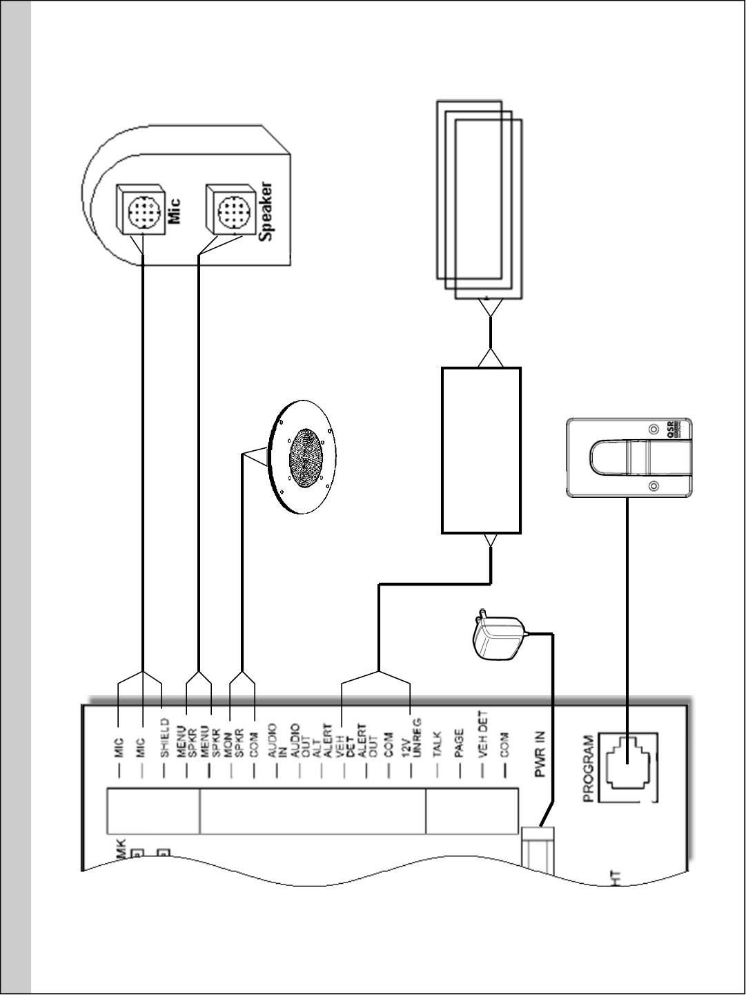
Loop Detector
Normally
Open Loop
QSR Performance Solutions - Connections To Base
Grill Speaker
(optional)
Power
Adaptor
Programming
Station
Vehicle Detector Loop
Speaker Post
Base Connection Terminal
Do not terminate shield at microphone end
6
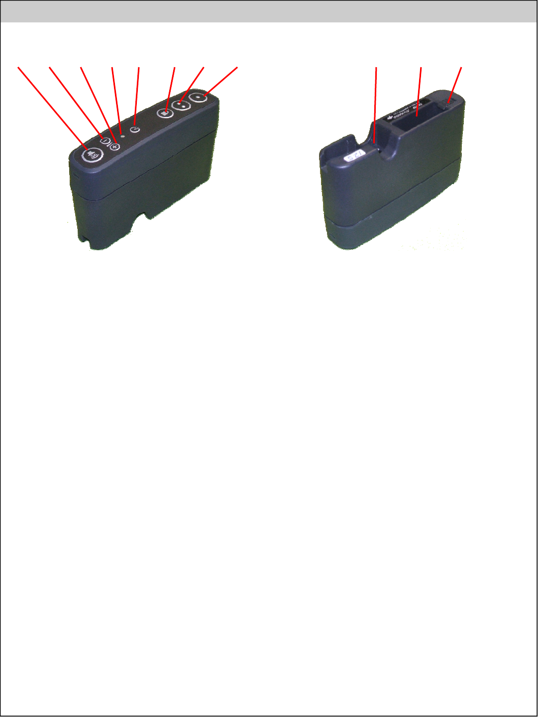
7. Talk 2
• Has the exact same function as Talk 1 when used with a single lane
system
• On Dual and Cross Lane systems Talk 2 will be programmed to
communicate with Lane 2
8. Talk 1
• Activates communication to outside speaker
• Will also be heard by other headsets and possibly grill speaker
(depending on system configuration)
• Can be used to test incoming and outgoing audio even when no car
is present
• On half-duplex systems, press to talk and release to listen
• On full-duplex systems incoming audio will be heard even while Talk
1 is pressed
• On Dual and Cross Lane systems Talk 1 will be programmed to
communicate with Lane 1
9. Headset Jack
• The 2 prong headset connector plugs in here
10. Battery Compartment
• Battery goes here
11. Battery Release
• Slide back to release battery from compartment
1. Page
• Press to talk to the other headsets without being heard at the
speaker post
• Belt-packs can be programmed for Page Monitor Mode, they will
only hear communication from other belt-packs that are using the
Page button and will not hear communication to or from the speaker
post
• To program a belt-pack for Page Monitor Mode, hold Page button
down while powering the headset on.
• To exit Page Monitor Mode turn the belt-pack off and back on
2. Volume Down
• Listening volume can be adjusted in 7 steps from the lowest to high-
est setting. When the belt-pack is powered on, the listening level will
be near mid-level and can be adjusted 3 steps up or 4 steps down.
A short tone will be heard each time the volume is adjusted. A long
tone is heard when the lowest or highest level is reached.
3. Volume Up
• Turns up incoming audio from speaker post. See previous section
for details
4. Power LED
• Green when belt-pack is powered on
• Red when talk-lock is in use
• Flashes green during channel programming
5. Power On / Off
• Press to turn power to belt-pack on or off
6. Talk Lock
• Used with a full-duplex system, press to activate hands-free com-
munication
• When car arrives at speaker post, press to activate. Communication
will automatically deactivate when car leaves speaker post and
automatically reactivate when next car arrives
• Press Talk 1 or Page to deactivate Talk Lock
• Only 1 belt-pack at a time can use Talk Lock and no other headsets
can talk to the speaker post
• Disabled or enabled by holding Talk Lock button down when the
headset is being powered up
QSR Performance Solutions Drive Thru - Belt-Pack
1 2 3 4 5 6 7 8 9 10 11
Bottom View