Inovonics Wireless 3B6OT9CWP Activity Sensor User Manual 05638B
Inovonics Wireless Corporation Activity Sensor 05638B
manual
1.24.14 05638B © Inovonics, 2014 - www.inovonics.com P/N 7102855 Rev. B
EN1240-60 EchoStream® Activity Sensor
Installation Instructions
1 Overview
The EN1240-60 activity sensor is designed specifically for residential and
senior living environments where a notification of a daily activity is
necessary. The EN1240-60 leverages the latest motion detector
technology, including white light and pet immunity, to ensure performance
accuracy. Selectable fixed sleep intervals of two, four, or six hours are used
to minimize wireless traffic in large installations, while confirming daily
resident activity. Check-in messages are sent every 60 minutes to provide
effective notification of recent resident activity even when the device is in
the fixed sleep cycle.
Note: For UL 2560 installations, refer to the EN6080 Area Control Gateway
Installation Instructions.
Note: In UL 2560 installations, transmitters send a check-in message every
60 minutes.
Caution: The EN1240-60 needs one minute for stabilization after power
up. During the stabilization period, the LED will blink twice per second, and
the EN1240-60 will not be operational.
Caution: Prior to operation, the EN1240-60 must be acclimated to the
temperature of the install environment for a period of 60 minutes.
Caution: The EN1240-60 activity sensor is not designed for use as a
security system motion detector.
1.1 Maximum Number of Repeaters for a UL 2560
Installation
To achieve the 99.99% alarm message reliability required for UL 2560
compliance, system installations must operate within the following limits for
end device and repeater counts.
1.2 Inovonics Wireless Contact Information
If you have any problems with this procedure, contact Inovonics Wireless
technical services:
• E-mail: support@inovonics.com
• Phone: (800) 782-2709; (303) 939-9336
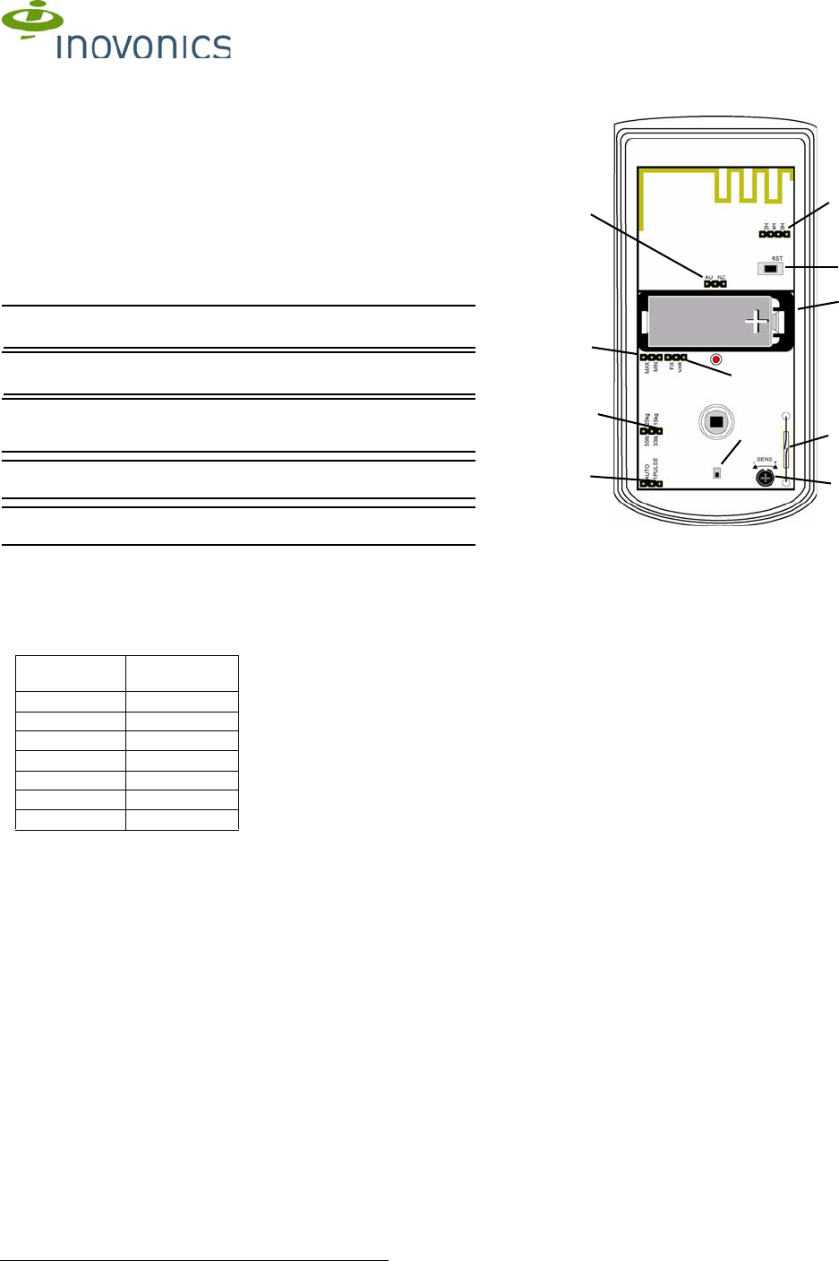
1.3 EN1240-60 Internal Components
Figure 1 EN1240-60 components
1.4 What’s In The Carton
• Three wall mount screws
• Three wall mount anchors
• One selection jumper
• One 3.0V lithium battery
2 Installation and Startup
2.1 Installation Notes
• These products are designed to be installed and maintained by
professional security technicians.
• Products are intended for indoor use.
• Manually test all products weekly.
End Devices Maximum
Repeaters
150 397
250 386
350 375
500 360
1000 313
2000 238
3000 184
AFrequency band
selection pins BReset button CPulse count selection
pins
DPet immunity selection
pins ETest mode reed
switch FSleep duration
selection pins
GSensitivity adjustment
dial HBattery ICase tamper switch
JSleep duration selection
pins KSleep time
selection pins
C
A
D
B
E
G
F
H
I
K
J

1.24.14 05638B © Inovonics, 2014 - www.inovonics.com P/N 7102855 Rev. B 2
2.2 Install/Replace Battery
To install the battery:
1. Release the housing screw and gently raise the cover.
Figure 2 Open the cover
2. Install the battery in the holder.
3. Press the reset button to initialize the transmitter.
Note: You must press the reset button each time the battery is changed.
2.3 Select the Frequency Band
EchoStream products are able to use a range of radio frequencies, and
must be configured for your geographic area. This product ships with a
default frequency range of 902-928 MHz for use in North America. If you
are using the product in North America, skip to section 2.4, “Select
Automatic/Pulse Count”; if you are using the product in Australia or New
Zealand, you will need to configure the transmitter.
4. Place a selection jumper on the appropriate frequency band selection
pins.
• Place the jumper on the right two pins, marked NZ, to set the
frequency range to 921-928 MHz for New Zealand.
• Place the jumper on the left two pins, marked AU, to set the frequency
range to 915-928 MHz for Australia.
5. Press the reset button to complete configuration.
Caution: When pressing the reset button, make sure you don’t also touch
the frequency band selection pins. Touching the frequency band selection
pins while pressing the reset button can inadvertently set the EN1240-60 to
the wrong frequency band.
2.4 Select Automatic/Pulse Count
The pulse count jumper setting provides control for normal or difficult
operating environments. Automatic pulse count is recommended for
reliable operation in environments subject to temperature fluctuations that
may cause false alarms. The single pulse count mode is more sensitive to
minor temperature variations, and should be used in sites where variant
heat sources will not cause false alarms.
6. Place a selection jumper on the appropriate pulse count selection pins.
• Place the jumper on the left two pins, marked AUTO, to select
automatic pulse count.
• Place the jumper on the right two pins, marked 1 PULSE, to select
single pulse count.
2.5 Select Fixed/Variable Sleep Time
The EN1240-60 activity sensor is shipped from the factory set for a fixed
sleep time. The fixed/variable sleep time setting should not be changed
without specific instruction from Inovonics technical services.
2.6 Select Sleep Duration
The EN1240-60 activity sensor is shipped from the factory set for a
minimum sleep duration. The sleep duration setting should not be changed
without specific instruction from Inovonics technical services.
2.7 Select Fixed Sleep Time
Alarm and Check-In Messages
The EN1240-60 sends two types of message: alarm and check-in. Alarm
messages are sent when the EN1240-60 first detects motion. Immediately
upon sending an alarm message, the EN1240-60 enters the selected sleep
cycle, during which no more alarm messages are sent. Check-in messages
are sent by the EN1240-60 every 60 minutes, even during the sleep cycle,
to ensure the EN1240-60 is still functional. Check-in messages also include
the alarm status as part of the check-in information.
Using Sleep Cycles
Typically, activity monitoring in senior living environments is performed
using a daily time window to confirm resident activity. The EN1240-60 sleep
interval can be set to two, four, or six hours. If you require multiple alarms
during your daily time window you should select a sleep time shorter than
your daily time window.
Setting Sleep Cycle Duration
To set sleep cycle duration:
7. Place a selection jumper on the appropriate sleep cycle duration
selection pins.
• Place the jumper on the left two pins, marked 2H, to set the sleep
cycle duration to two hours.
• Place the jumper on the middle two pins, marked 4H, to set the sleep
cycle duration to four hours.
• Place the jumper on the right two pins, marked 6H, to set the sleep
cycle duration to six hours.
Note: Selection jumpers are included in the hardware bag.
2.8 Select Pet Immunity
Pet immunity allows the EN1240-60 to ignore the movement of small
animals.
8. Place a selection jumper on the appropriate pet immunity selection
pins.
• Place the jumper on the left two pins, marked 55lb/25kg to select pet
immunity for animals up to 55 pounds (25 kilograms) in weight.
• Place the jumper on the right two pins, marked 33lb/15kg to select pet
immunity for animals up to 33 pounds (15 kilograms).
Note: If neither option is selected, the EN1240-60 will default to the 55lb/
25kg selection.
2.9 Adjust sensitivity
The sensitivity of the activity sensor can be adjusted to fit your specific
application. To adjust sensitivity:
9. Use a philip’s head screwdriver to turn the sensitivity adjustment dial.
• Turn the dial to the left, towards the minus sign, to decrease the
activity sensor’s sensitivity.
• Turn the dial to the right, towards the plus sign, to increase the activity
sensor’s sensitivity.
2.10 Register the Transmitter
The EN1240-60 must be registered with the system receiver in order to be
monitored and supervised. Each EN1240-60 has a unique factory-
programmed identification number.
Note: The transmitter’s unique identification number is the eight digit serial
number found on the serial number label.
Refer to the receiver installation instructions for details about registering
the transmitter.
10. When prompted, press the reset button.
11. Replace the EN1240-60 cover.
12. Replace the housing screw.
Caution: The EN1240-60 should be tested after registration to ensure
operation. To test the EN1240-60, activate each of the conditions and
ensure an appropriate response.
Note: The EN1240-60 retains programming data in non-volatile memory. It
does not require re-programming after loss of power.
2.11 Mount the Transmitter
Mount the transmitter.
13. Remove the EN1240-60 printed circuit board from the housing.
14. Use the included hardware to mount the EN1240-60 housing back plate
to the mounting surface.
Housing
screw
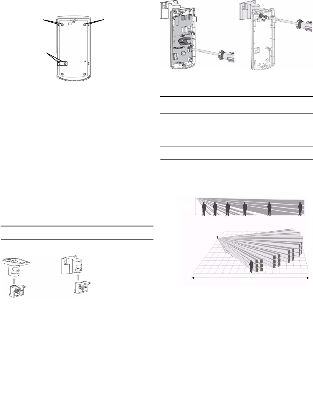
1.24.14 05638B © Inovonics, 2014 - www.inovonics.com P/N 7102855 Rev. B 3
a. If using the wall tamper function for increased security, mount
the housing back plate per Figure 3, ensuring the tamper switch
is depressed.
Figure 3 EN1240-60 mounting back plate
b. If not using the wall tamper, mount the housing back plate
using all appropriate hardware.
3 Mounting Considerations
The following should be considered when mounting the EN1240-60:
• The activity sensor should be mounted such that the expected
intrusion motion is perpendicular to the protection zones
• The activity sensor may not detect motion behind obstructions,
including blinds, curtains, and drapes
• The activity sensor should be mounted on a solid, vibration-free
mounting surface
• Fans and blowers can cause false alarms.
• The following may cause false alarms:
- Fans
- Blowers
- Drafts
- Windows
- Heat and cooling sources
- Sunlight
- Animals
4 Optional Ceiling/Wall Mount Application
The optional ceiling and wall mount brackets are available separately from
Inovonics, part number ACC665.
Note: Applications that require the back tamper cannot use the ceiling or
wall mount bracket.
Figure 4 Ceiling and wall mount brackets
To mount a ceiling or wall bracket:
1. Remove the pcb board.
2. Attach the housing to the bracket.
Figure 5 Remove the pcb board and attach the housing to the bracket
3. Replace the pcb board.
5 Test the EN1240-60
Caution: The EN1240-60 should be tested after registration, and at least
once a year thereafter, to ensure operation. To test the EN1240-60, activate
each of the conditions and ensure an appropriate response.
5.1 Perform a Walk Test
The walk test is performed to ensure motion is sensed and an RF
transmission results. To perform a walk test:
1. Swipe a magnet past the reed switch. The five minute walk test will
begin; every time motion is sensed, the LED will light.
Note: During walk test, the EN1240-60 will not transmit alarms when
motion is detected; only the LED will light.
2. Walk in front of the activity sensor to test the sensor.
3. After five minutes the walk test will automatically end.
6 Operation
The EN1240-60 transmitter signals an alarm condition when motion is
detected by the sensor.
Figure 6 Standard mounting height and range
7 US Patent Numbers
• 7,154,866
• 7,554,932
• 7,746,804
• Other patents pending
Mount either
corner or wall
with screw only
Mount either
corner or wall with
screw and wall
anchor
Mount either corner
or wall with screw
only
Ceiling mount Wall mount
6’ 10”-
8’ 10”
49’

1.24.14 05638B © Inovonics, 2014 - www.inovonics.com P/N 7102855 Rev. B 4
8 Specifications
Dimensions: 4.5”H x 2.5”Wx 1.6”D (11.4 cm x 6.4 cm x 4.1 cm)
Detection method: Quad element PIR
Storage temperature: -4° to 140°F (-20° to 60°C)
Operating temperature: 32° to 122°F (0° to 50°C), 90% relative humidity,
non-condensing
Humidity: 0 - 90% (non-condensing)
Typical battery life: 2 years
Battery: 3V LiMnO2, BAT604 (Panasonic CR123A or Duracell DL123A)
Power requirement: 3VDC, 60 mA
Temperature compensation: Yes
Tamper: Housing and wall tamper
PIR RF interference immunity: Greater than 30 v/m 26 MHz - 1 GHz
Stabilization period: one minute
Alarm lockout time: two, four, or six hours
Walk test period: five minutes
Mounting height: 6’ 10” to 8’ 10” (2.1 to 2.7m)
UL certification: UL 2560
Compatible receiver for UL 2560 installations: EN6080
Compatible repeater for UL 2560 installations: EN5040-20T
Note: In a UL 2560 installation, the EN1240-60 may be used with
completed emergency call systems for assisted living and independent
living facilities.
9 Television and Radio Interference
This equipment has been tested and found to comply with the limits for a
Class B digital device, pursuant to Part 15 of the FCC Rules. These limits
are designed to provide reasonable protection against harmful interference
in a residential installation. This equipment generates, uses and can
radiate radio frequency energy and, if not installed and used in accordance
with the instructions, may cause harmful interference to radio
communications. However, there is no guarantee that interference will not
occur in a particular installation. If this equipment does cause harmful
interference to radio or television reception, which can be determined by
turning the equipment off and on, the user is encouraged to try to correct
the interference by one or more of the following measures:
• Reorient or relocate the receiving antenna.
• Increase the separation between the equipment and receiver.
• Connect the equipment into an outlet on a circuit different from that to
which the receiver is connected.
• Consult the dealer or an experienced radio/TV technician for help.
10 FCC Part 15 and Industry Canada Compliance
This device complies with part 15 of the FCC Rules and Industry Canada
license-exempt RSS standard(s). Operation is subject to the following two
conditions: (1) this device may not cause interference, and (2) this device
must accept any interference, including interference that may cause
undesired operation of the device.
Le présent appareil est conforme aux CNR d'Industrie Canada applicables
aux appareils radio exempts de licence. L'exploitation est autorisée aux
deux conditions suivantes : (1) l'appareil ne doit pas produire de brouillage,
et (2) l'utilisateur de l'appareil doit accepter tout brouillage radioélectrique
subi, même si le brouillage est susceptible d'en compromettre le
fonctionnement.
11 Warranty/Disclaimer
Caution: Changes or modifications not expressly approved by the party
responsible for compliance could void the user's authority to operate the
equipment.
Inovonics Wireless Corporation ("Inovonics") warrants its EchoStream
products ("Product" or "Products") to conform to its own specifications and
to be free of defects in materials and workmanship under normal use for a
period of thirty-six (36) months from the date of manufacture. Within the
warranty period, Inovonics will repair or replace, at its option, all or any part
of the warranted Product. Inovonics will not be responsible for dismantling
and/or reinstallation charges. To exercise the warranty, the User ("User",
"Installer" or "Consumer") must work directly through their authorized
distributor who will be given a Return Material Authorization ("RMA")
number by Inovonics. Details of shipment will be arranged directly through
the authorized distributor.
This warranty is void in cases of improper installation, misuse, failure to
follow installation and operating instructions, alteration, accident or
tampering, and repair by anyone other than Inovonics.
This warranty is exclusive and expressly in lieu of all other warranties,
obligations or liabilities, whether written, oral, express, or implied. There is
no warranty by Inovonics that Inovonics product will be merchantable or fit
for any particular purpose, nor is there any other warranty, expressed or
implied, except as such is expressly set forth herein. In no event shall
Inovonics be liable for an incidental, consequential, indirect, special, or
exemplary damages, including but not limited to loss of profit, revenue, or
contract, loss of use, cost of down time, or interruption of business, nor any
claim made by distributor's customers or any other person or entity.
This warranty will not be modified or extended. Inovonics does not
authorize any person to act on its behalf to modify or extend this warranty.
This warranty will apply only to Inovonics Products. Inovonics will not be
liable for any direct, incidental, or consequential damage or loss
whatsoever, caused by the malfunction of Product due to products,
accessories, or attachments of other manufacturers, including batteries,
used in conjunction with Inovonics Products.