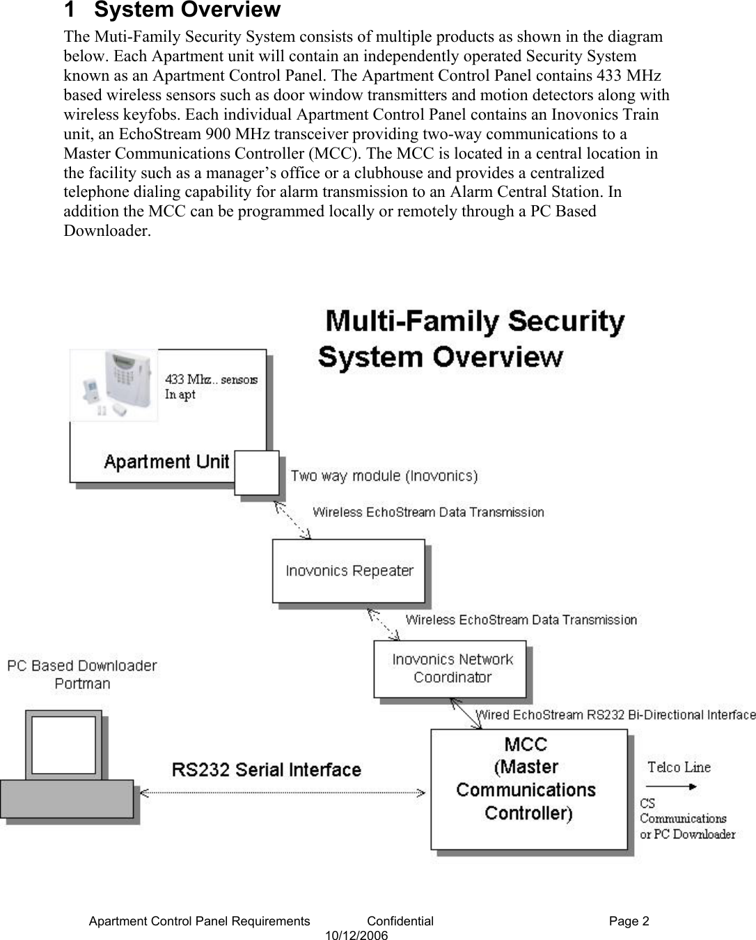
Inovonics Wireless 3B6PORPEN Security System Remote Control User Manual ACP design manual 060923
Inovonics Wireless Corporation Security System Remote Control ACP design manual 060923
UserManual.wiki
>
Inovonics Wireless
>
3B6PORPEN User Manual
user manual
Navigation menu
Upload a User Manual
Namespaces
Wiki Guide
HTML
PDF
Info
Views
User Manual
Discussion / Help
Navigation
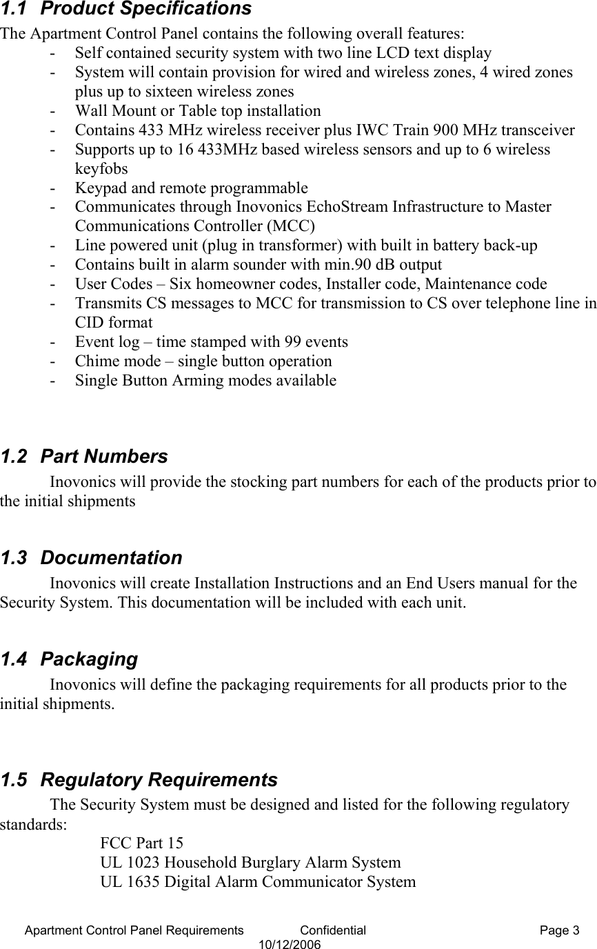
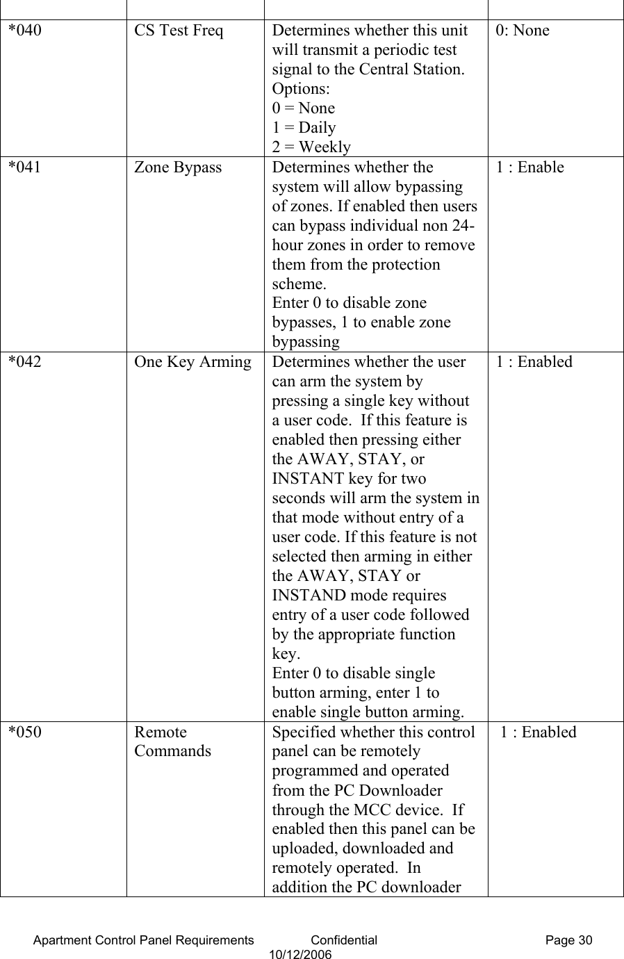
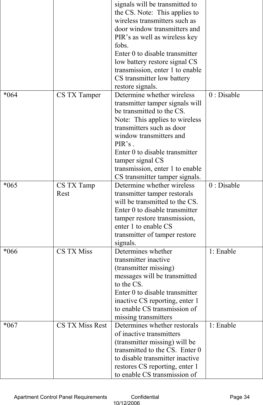
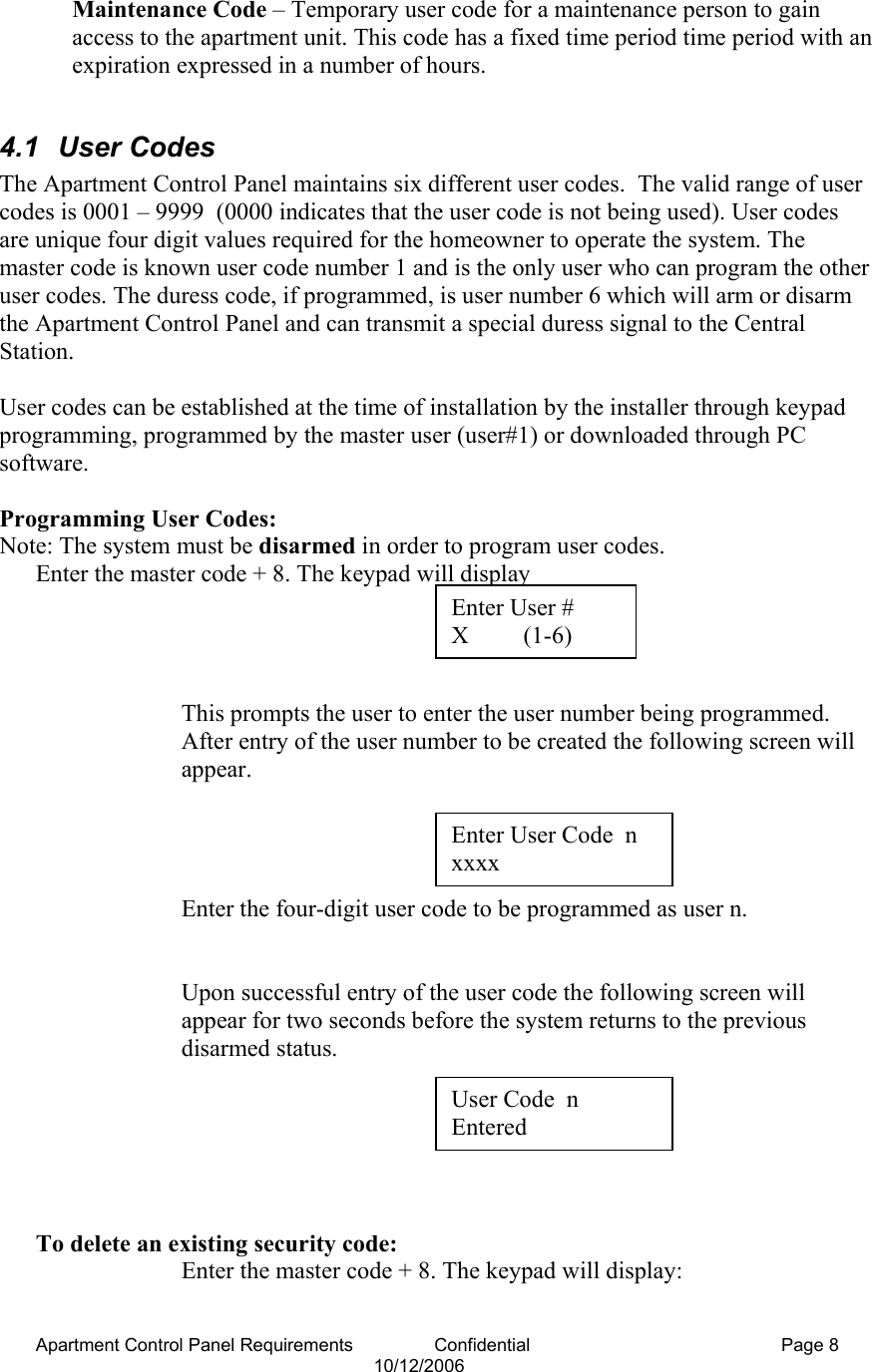
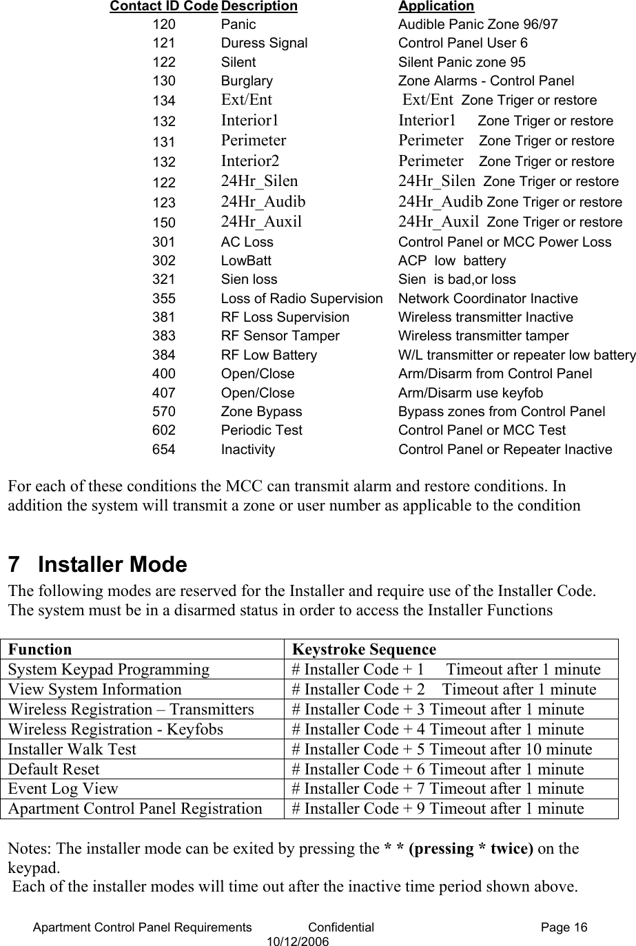
![Apartment Control Panel Requirements Confidential Page 6 10/12/2006 2.2 EEPROM Memory The Apartment Control Panel contains all programmable data in electrically erasable, non-volatile EEPROM memory, so it will not be lost in the event of a power failure. All functions will perform only after programming. Programming can be performed through keypad programming or remotely through the PC downloader communicating through the MCC using the Inovonics Wireless Network. 3 Zone Definitions 3.1 Zone Type and Definition The Apartment Control Panel supports the following zone types. These zone types can be programmed to each of the sixteen wireless zones. If the zone types are programmed through the keypads they will be entered as keypad configurable options *001 - *016. Note: These zone types apply to the wireless zone 01 – 16 and do not apply to keyfobs. 3.1.1 [00] Null Zone The zone is vacant. Unused zones should be programmed as null zones 3.1.2 [01] Exit/Entry Zone This zone type, normally used for entry/exit doors, can be violated during the exit delay period without causing an alarm. This zone type provides an entry and exit delay period while arming. During this delay period, the system will not cause an alarm, even if the zone is violated. Once the exit delay period has expired, opening the zone will start the entry delay timer. During the entry delay time, the keypad buzzer sounds to advise the user that the system should be disarmed. If the panel is disarmed before the entry time expires, no alarm will be generated. The exit delay time can be programmed through option *81 and the duration of the exit delay can be programmed in option *82. 3.1.3 [02] Interior Zone with Follow Up This zone is used for those positions that need an entry delay period when exit/entry zone are violated, such as an entrance containing motion detectors. This allows users to pass through motion detectors to get to a keypad. If the zone is violated before the entry delay period has begun, it will cause an instant alarm. The delay time of this zone is the same as that of exit/entry zone. 3.1.4 [03] Perimeter Zone (Instant) This zone is used for exterior zones such as windows, patio doors, as well as glass-break detectors. It causes an instant alarm if the zone is violated when the panel is armed. Perimeter zones do not use the exit/entry times.](https://usermanual.wiki/Inovonics-Wireless/3B6PORPEN/User-Guide-718752-Page-6.png)
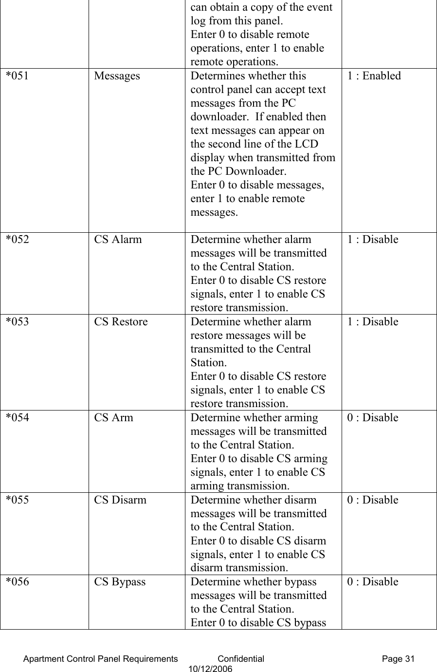
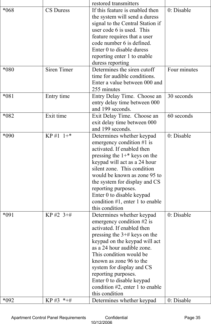
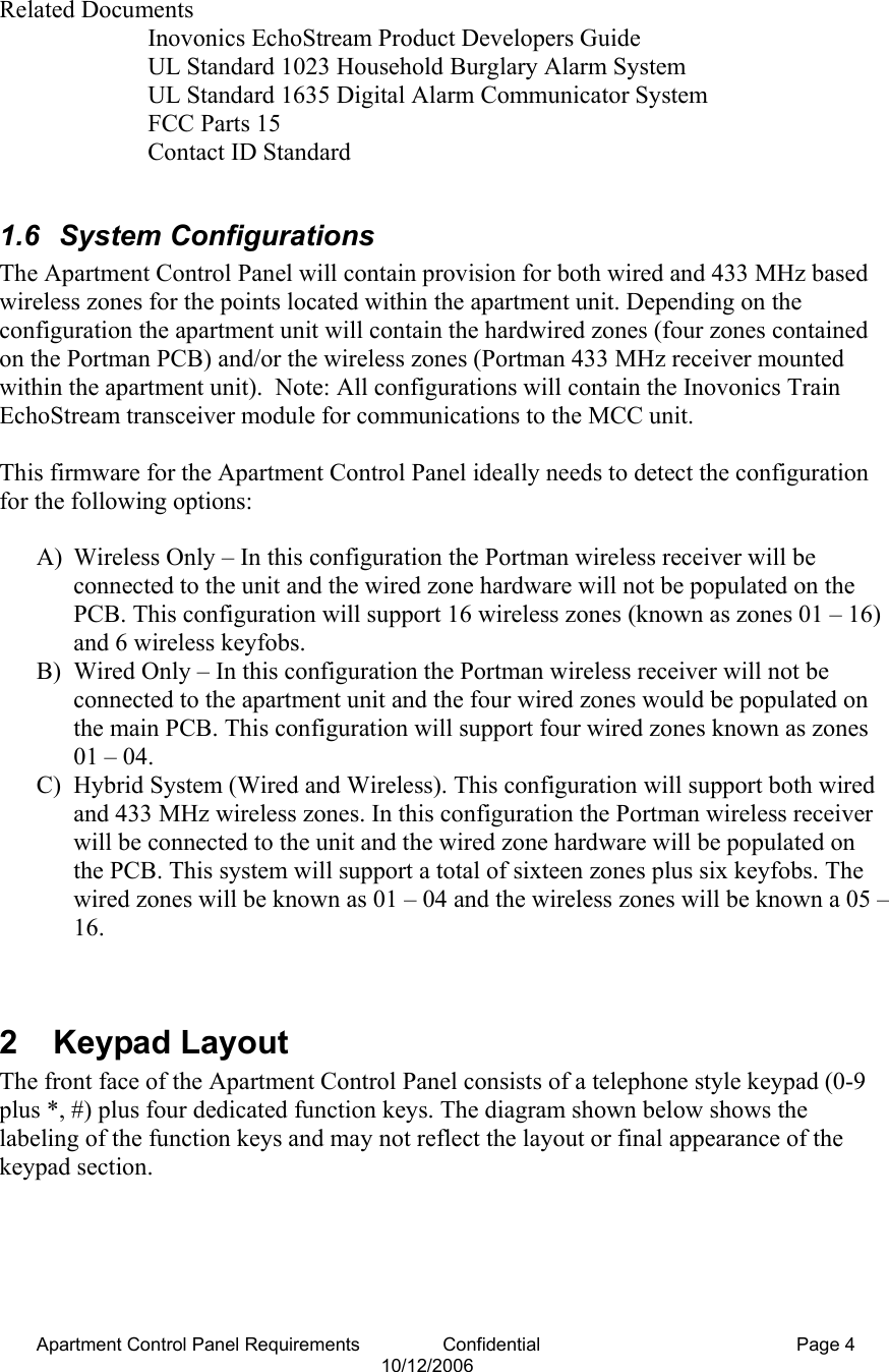
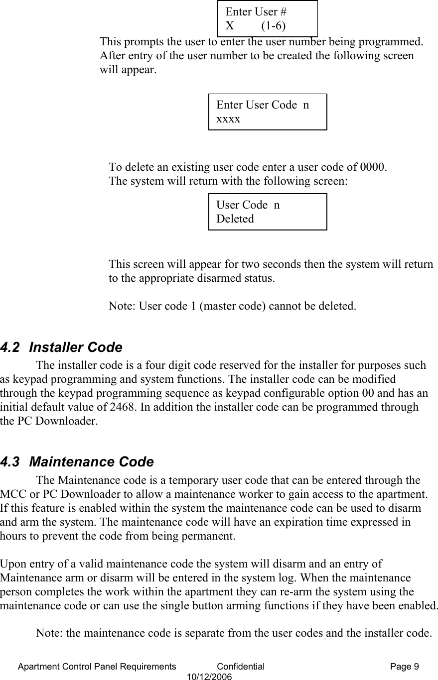
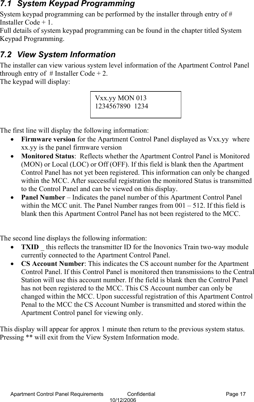
![Apartment Control Panel Requirements Confidential Page 7 10/12/2006 3.1.5 [04] Interior Zone with Time Delay This zone is similar to the interior zone with follow up. The difference being that the delay period is independent of whether the exit/entry zone is violated. 3.1.6 [06] 24 Hour Silent Zone This zone is normally used for zones such as a panic button, which sends an emergency signal to the Central Station. This is a silent condition indicating that the zone number will not display on the keypad, and the keypad and sirens do not sound. This zone functions independent of the system arming status. 3.1.7 [07] 24 Hour Audible Zone This type is used for zones such as a panic button. This zone type sends the emergency signal to the Central Station and generates an audible signal. When triggered, the siren will activate and the zone number will appear on the keypad, and the communicator reports to the control station. This zone functions independent of the arming status. 3.1.8 [08] 24 Hour Auxiliary Zone This type is used for emergency conditions that will report to the Central Station. The keypad will generate sounds and the zone number will appear on the display, however the external siren will not sound. This zone type functions independently of the arming status. 3.2 Arming Mode and Zone Type The following table summarizes the different system arming modes. Note: 24 hour zones are always active and are independent of the system arming status. Arming mode Exit delay Entry delay Effective zones Bypassed zones Purpose Away Yes Yes All No Leaving the premise Stay Yes Yes All except interior zones Interior zone Stay at homeInstant Yes No All except interior zones Interior zone Nighttime, everyone home 4 User Codes The Apartment Control Panel maintains three types of codes to operate the system: User Codes – These are the four digit codes used by the homeowner to operate the Apartment Control Panel Installer Code – Dedicated four digit code reserved for the Alarm Installer for uses such as system programming and troubleshooting](https://usermanual.wiki/Inovonics-Wireless/3B6PORPEN/User-Guide-718752-Page-7.png)
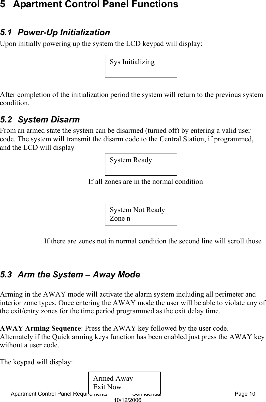
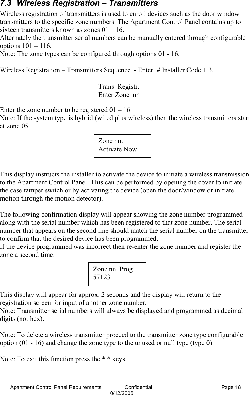

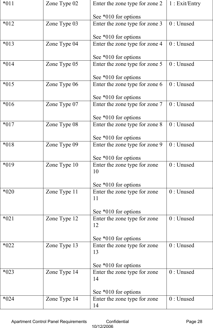
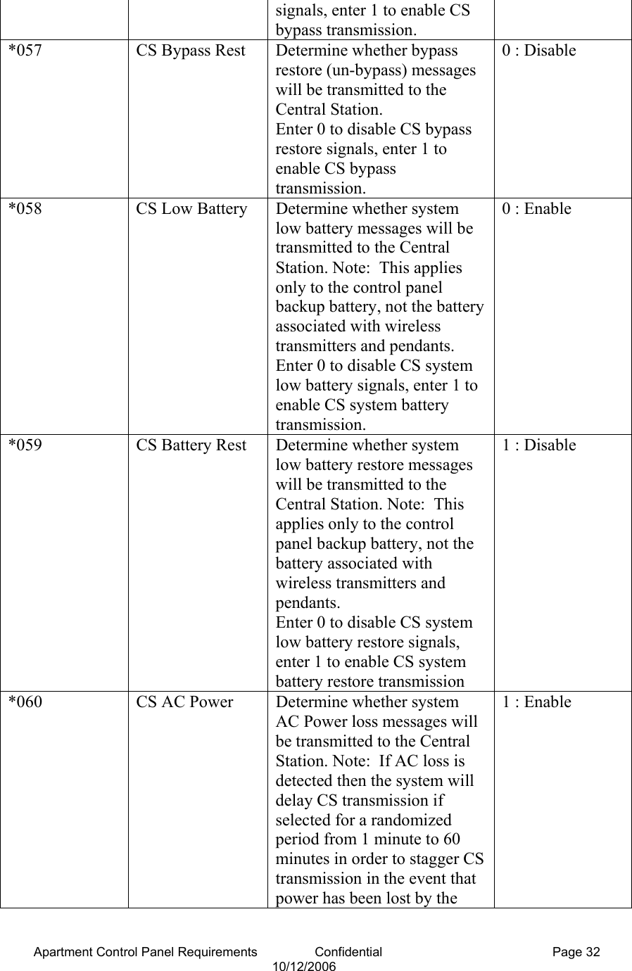
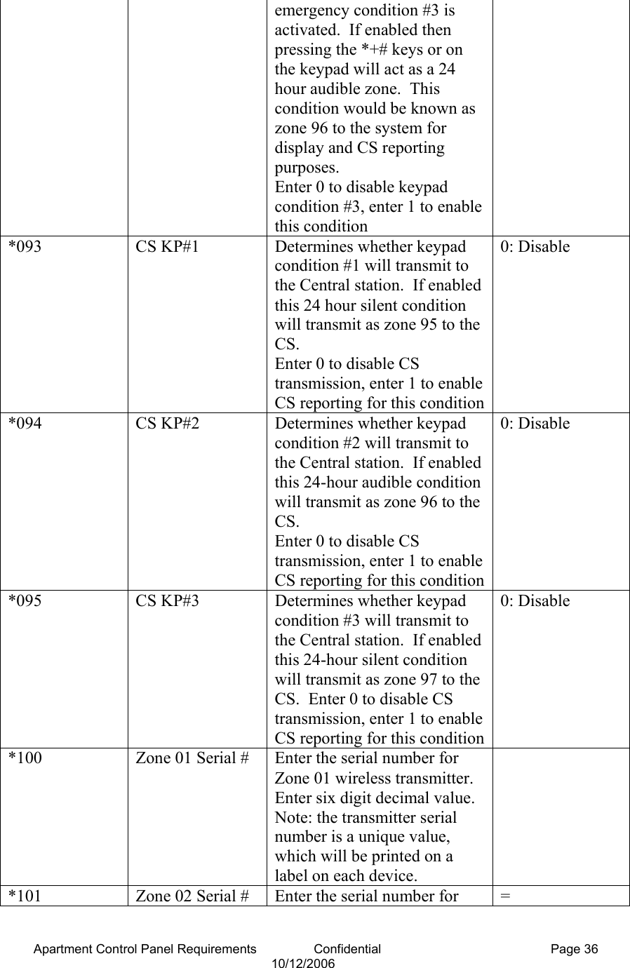
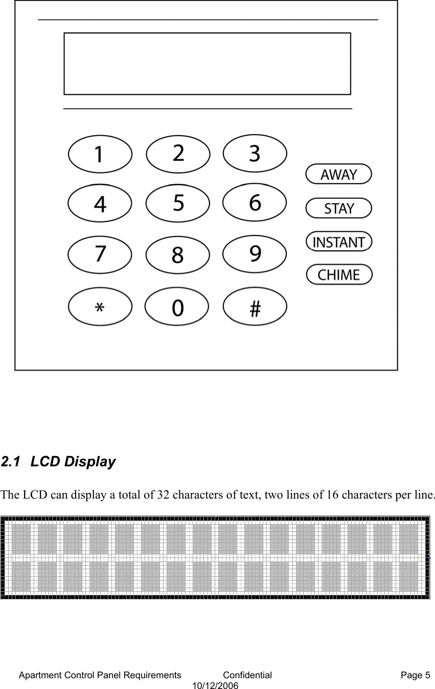
![Apartment Control Panel Requirements Confidential Page 25 10/12/2006 The installer through the keypad can program the Apartment Control Panel . System programming can occur at the time of installation or at any time afterwards to view or modify the configurable options of the Apartment Control Panel. Note: The system must be disarmed in order to enter the keypad programming mode. In addition the system can be programmed remotely through the PC downloader if the downloading option has been enabled in the programming sequence: System Programming Keystrokes: Enter Programming mode: # [Installer Code] 1 Access direct option number * [option number] ex. *020 proceed to option 020 Move to next position within option: # Enter Data 0-9 Note: Hex digits A-F no longer needed within the apartment system, serial numbers for the transmitters and keyfobs will be entered as the decimal value of the serial number. Exit Programming * * key Enter # [Installer Code] + 1 to enter keypad programming. LCD screen will display: Navigation Rules: • Enter * + option number to advance a specific configurable option (allows modification) • Enter # + the option number to review the item’s current programming. • Pressing the # button to review the rest of the items. Note: Upon entering keypad programming the system will revert to the previous disarmed status automatically after 1 minute of inactivity. 8.1 Keypad Configurable Options The keypad configurable options have been organized into the following categories: 000 – 005 Setup Questions (installer code, Acct Number, Mon Type , Panel Number ,site ID, network ID) 010 – 025 Zone Types 030 – 035 User Codes 040 – 068 CS Reporting/System Attributes Enter Option. nnn](https://usermanual.wiki/Inovonics-Wireless/3B6PORPEN/User-Guide-718752-Page-25.png)