Inovonics Wireless 3B6PORPEN Security System Remote Control User Manual ACP design manual 060923
Inovonics Wireless Corporation Security System Remote Control ACP design manual 060923
user manual

Apartment Control Panel Requirements Confidential Page 1
10/12/2006
Apartment Control Panel
Market Requirements Document
Revision History
Rev
Level Description Date
1 Initial Release
2 Comments from Design Review for User Interface Section 4/22/06
3 Revised Registration, Alarm transmission, modified System
Information View
5/22/06
4 Additional Comments from 5/25/06 review 5/25/06
5 Comments from 5/31/06 review 6/01/06
6 Revised system overview diagram, sect. 7 clarifications 6/02/06
CONFIDENTIAL DOCUMENTATION
The information contained in this document is confidential to and the sole property of Inovonics
Wireless Corporation. Receipt of this information requires the existence and full acceptance of the
terms and conditions of a Non-Disclosure Agreement signed by Inovonics Wireless Corporation and
the Recipient. The documentation is not to be reproduced or redistributed, except as provided in the
Non-Disclosure Agreement.
Apartment Control Panel Requirements Confidential Page 2
10/12/2006
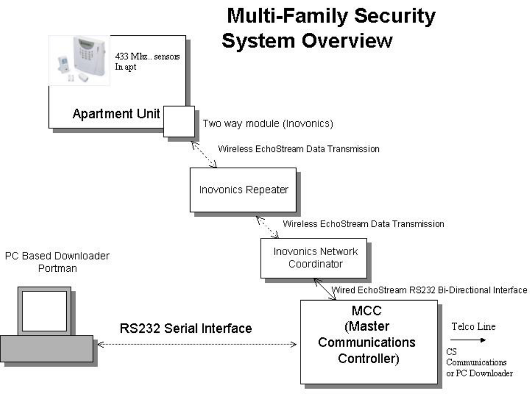
1 System Overview
The Muti-Family Security System consists of multiple products as shown in the diagram
below. Each Apartment unit will contain an independently operated Security System
known as an Apartment Control Panel. The Apartment Control Panel contains 433 MHz
based wireless sensors such as door window transmitters and motion detectors along with
wireless keyfobs. Each individual Apartment Control Panel contains an Inovonics Train
unit, an EchoStream 900 MHz transceiver providing two-way communications to a
Master Communications Controller (MCC). The MCC is located in a central location in
the facility such as a manager’s office or a clubhouse and provides a centralized
telephone dialing capability for alarm transmission to an Alarm Central Station. In
addition the MCC can be programmed locally or remotely through a PC Based
Downloader.
Apartment Control Panel Requirements Confidential Page 3
10/12/2006
1.1 Product Specifications
The Apartment Control Panel contains the following overall features:
- Self contained security system with two line LCD text display
- System will contain provision for wired and wireless zones, 4 wired zones
plus up to sixteen wireless zones
- Wall Mount or Table top installation
- Contains 433 MHz wireless receiver plus IWC Train 900 MHz transceiver
- Supports up to 16 433MHz based wireless sensors and up to 6 wireless
keyfobs
- Keypad and remote programmable
- Communicates through Inovonics EchoStream Infrastructure to Master
Communications Controller (MCC)
- Line powered unit (plug in transformer) with built in battery back-up
- Contains built in alarm sounder with min.90 dB output
- User Codes – Six homeowner codes, Installer code, Maintenance code
- Transmits CS messages to MCC for transmission to CS over telephone line in
CID format
- Event log – time stamped with 99 events
- Chime mode – single button operation
- Single Button Arming modes available
1.2 Part Numbers
Inovonics will provide the stocking part numbers for each of the products prior to
the initial shipments
1.3 Documentation
Inovonics will create Installation Instructions and an End Users manual for the
Security System. This documentation will be included with each unit.
1.4 Packaging
Inovonics will define the packaging requirements for all products prior to the
initial shipments.
1.5 Regulatory Requirements
The Security System must be designed and listed for the following regulatory
standards:
FCC Part 15
UL 1023 Household Burglary Alarm System
UL 1635 Digital Alarm Communicator System
Apartment Control Panel Requirements Confidential Page 4
10/12/2006
Related Documents
Inovonics EchoStream Product Developers Guide
UL Standard 1023 Household Burglary Alarm System
UL Standard 1635 Digital Alarm Communicator System
FCC Parts 15
Contact ID Standard
1.6 System Configurations
The Apartment Control Panel will contain provision for both wired and 433 MHz based
wireless zones for the points located within the apartment unit. Depending on the
configuration the apartment unit will contain the hardwired zones (four zones contained
on the Portman PCB) and/or the wireless zones (Portman 433 MHz receiver mounted
within the apartment unit). Note: All configurations will contain the Inovonics Train
EchoStream transceiver module for communications to the MCC unit.
This firmware for the Apartment Control Panel ideally needs to detect the configuration
for the following options:
A) Wireless Only – In this configuration the Portman wireless receiver will be
connected to the unit and the wired zone hardware will not be populated on the
PCB. This configuration will support 16 wireless zones (known as zones 01 – 16)
and 6 wireless keyfobs.
B) Wired Only – In this configuration the Portman wireless receiver will not be
connected to the apartment unit and the four wired zones would be populated on
the main PCB. This configuration will support four wired zones known as zones
01 – 04.
C) Hybrid System (Wired and Wireless). This configuration will support both wired
and 433 MHz wireless zones. In this configuration the Portman wireless receiver
will be connected to the unit and the wired zone hardware will be populated on
the PCB. This system will support a total of sixteen zones plus six keyfobs. The
wired zones will be known as 01 – 04 and the wireless zones will be known a 05 –
16.
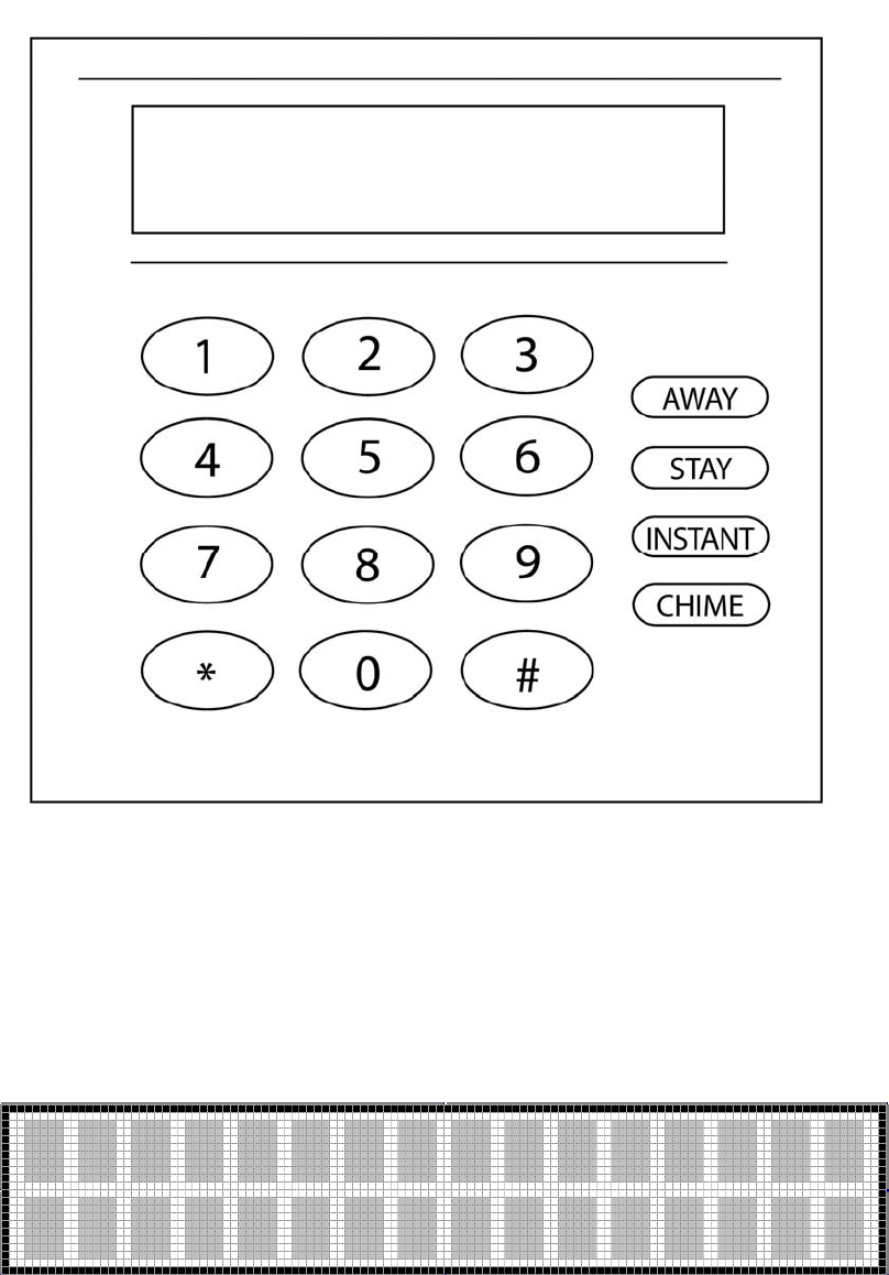
2 Keypad Layout
The front face of the Apartment Control Panel consists of a telephone style keypad (0-9
plus *, #) plus four dedicated function keys. The diagram shown below shows the
labeling of the function keys and may not reflect the layout or final appearance of the
keypad section.
Apartment Control Panel Requirements Confidential Page 5
10/12/2006
2.1 LCD Display
The LCD can display a total of 32 characters of text, two lines of 16 characters per line.
Apartment Control Panel Requirements Confidential Page 6
10/12/2006
2.2 EEPROM Memory
The Apartment Control Panel contains all programmable data in electrically erasable,
non-volatile EEPROM memory, so it will not be lost in the event of a power failure. All
functions will perform only after programming. Programming can be performed through
keypad programming or remotely through the PC downloader communicating through
the MCC using the Inovonics Wireless Network.
3 Zone Definitions
3.1 Zone Type and Definition
The Apartment Control Panel supports the following zone types. These zone types can be
programmed to each of the sixteen wireless zones. If the zone types are programmed
through the keypads they will be entered as keypad configurable options *001 - *016.
Note: These zone types apply to the wireless zone 01 – 16 and do not apply to keyfobs.
3.1.1 [00] Null Zone
The zone is vacant. Unused zones should be programmed as null zones
3.1.2 [01] Exit/Entry Zone
This zone type, normally used for entry/exit doors, can be violated during the exit delay
period without causing an alarm. This zone type provides an entry and exit delay period
while arming. During this delay period, the system will not cause an alarm, even if the
zone is violated. Once the exit delay period has expired, opening the zone will start the
entry delay timer. During the entry delay time, the keypad buzzer sounds to advise the
user that the system should be disarmed.
If the panel is disarmed before the entry time expires, no alarm will be generated. The
exit delay time can be programmed through option *81 and the duration of the exit delay
can be programmed in option *82.
3.1.3 [02] Interior Zone with Follow Up
This zone is used for those positions that need an entry delay period when exit/entry zone
are violated, such as an entrance containing motion detectors. This allows users to pass
through motion detectors to get to a keypad.
If the zone is violated before the entry delay period has begun, it will cause an instant
alarm. The delay time of this zone is the same as that of exit/entry zone.
3.1.4 [03] Perimeter Zone (Instant)
This zone is used for exterior zones such as windows, patio doors, as well as glass-break
detectors. It causes an instant alarm if the zone is violated when the panel is armed.
Perimeter zones do not use the exit/entry times.

Apartment Control Panel Requirements Confidential Page 7
10/12/2006
3.1.5 [04] Interior Zone with Time Delay
This zone is similar to the interior zone with follow up. The difference being that the
delay period is independent of whether the exit/entry zone is violated.
3.1.6 [06] 24 Hour Silent Zone
This zone is normally used for zones such as a panic button, which sends an emergency
signal to the Central Station. This is a silent condition indicating that the zone number
will not display on the keypad, and the keypad and sirens do not sound. This zone
functions independent of the system arming status.
3.1.7 [07] 24 Hour Audible Zone
This type is used for zones such as a panic button. This zone type sends the emergency
signal to the Central Station and generates an audible signal. When triggered, the siren
will activate and the zone number will appear on the keypad, and the communicator
reports to the control station. This zone functions independent of the arming status.
3.1.8 [08] 24 Hour Auxiliary Zone
This type is used for emergency conditions that will report to the Central Station. The
keypad will generate sounds and the zone number will appear on the display, however the
external siren will not sound. This zone type functions independently of the arming status.
3.2 Arming Mode and Zone Type
The following table summarizes the different system arming modes. Note: 24 hour zones
are always active and are independent of the system arming status.
Arming
mode
Exit delay Entry delay Effective
zones
Bypassed
zones
Purpose
Away Yes Yes All No Leaving the
premise
Stay Yes Yes All except
interior
zones
Interior zone Stay at home
Instant Yes No All except
interior
zones
Interior zone Nighttime,
everyone
home
4 User Codes
The Apartment Control Panel maintains three types of codes to operate the system:
User Codes – These are the four digit codes used by the homeowner to operate
the Apartment Control Panel
Installer Code – Dedicated four digit code reserved for the Alarm Installer for
uses such as system programming and troubleshooting

Apartment Control Panel Requirements Confidential Page 8
10/12/2006
Maintenance Code – Temporary user code for a maintenance person to gain
access to the apartment unit. This code has a fixed time period time period with an
expiration expressed in a number of hours.
4.1 User Codes
The Apartment Control Panel maintains six different user codes. The valid range of user
codes is 0001 – 9999 (0000 indicates that the user code is not being used). User codes
are unique four digit values required for the homeowner to operate the system. The
master code is known user code number 1 and is the only user who can program the other
user codes. The duress code, if programmed, is user number 6 which will arm or disarm
the Apartment Control Panel and can transmit a special duress signal to the Central
Station.
User codes can be established at the time of installation by the installer through keypad
programming, programmed by the master user (user#1) or downloaded through PC
software.
Programming User Codes:
Note: The system must be disarmed in order to program user codes.
Enter the master code + 8. The keypad will display
This prompts the user to enter the user number being programmed.
After entry of the user number to be created the following screen will
appear.
Enter the four-digit user code to be programmed as user n.
Upon successful entry of the user code the following screen will
appear for two seconds before the system returns to the previous
disarmed status.
To delete an existing security code:
Enter the master code + 8. The keypad will display:
Enter User #
X (1-6)
Enter User Code n
xxxx
User Code n
Entered

Apartment Control Panel Requirements Confidential Page 9
10/12/2006
This prompts the user to enter the user number being programmed.
After entry of the user number to be created the following screen
will appear.
To delete an existing user code enter a user code of 0000.
The system will return with the following screen:
This screen will appear for two seconds then the system will return
to the appropriate disarmed status.
Note: User code 1 (master code) cannot be deleted.
4.2 Installer Code
The installer code is a four digit code reserved for the installer for purposes such
as keypad programming and system functions. The installer code can be modified
through the keypad programming sequence as keypad configurable option 00 and has an
initial default value of 2468. In addition the installer code can be programmed through
the PC Downloader.
4.3 Maintenance Code
The Maintenance code is a temporary user code that can be entered through the
MCC or PC Downloader to allow a maintenance worker to gain access to the apartment.
If this feature is enabled within the system the maintenance code can be used to disarm
and arm the system. The maintenance code will have an expiration time expressed in
hours to prevent the code from being permanent.
Upon entry of a valid maintenance code the system will disarm and an entry of
Maintenance arm or disarm will be entered in the system log. When the maintenance
person completes the work within the apartment they can re-arm the system using the
maintenance code or can use the single button arming functions if they have been enabled.
Note: the maintenance code is separate from the user codes and the installer code.
Enter User #
X (1-6)
Enter User Code n
xxxx
User Code n
Deleted

Apartment Control Panel Requirements Confidential Page 10
10/12/2006
5 Apartment Control Panel Functions
5.1 Power-Up Initialization
Upon initially powering up the system the LCD keypad will display:
After completion of the initialization period the system will return to the previous system
condition.
5.2 System Disarm
From an armed state the system can be disarmed (turned off) by entering a valid user
code. The system will transmit the disarm code to the Central Station, if programmed,
and the LCD will display
If all zones are in the normal condition
If there are zones not in normal condition the second line will scroll those
5.3 Arm the System – Away Mode
Arming in the AWAY mode will activate the alarm system including all perimeter and
interior zone types. Once entering the AWAY mode the user will be able to violate any of
the exit/entry zones for the time period programmed as the exit delay time.
AWAY Arming Sequence: Press the AWAY key followed by the user code.
Alternately if the Quick arming keys function has been enabled just press the AWAY key
without a user code.
The keypad will display:
Sys Initializing
System Ready
System Not Ready
Zone n
Armed Away
Exit Now

Apartment Control Panel Requirements Confidential Page 11
10/12/2006
For the duration of the exit time period the second line of the display will display exit
now alerting the user to leave through the exit/entry zones. The keypad buzzer will sound
during the exit delay time.
At the end of the exit delay period the keypad sounder will stop and if all of the zones are
in normal (secure status) then the system will be armed in the away mode with the
following LCD display.
If zones are still violated after expiration of the exit delay then the system will go into
ALARM.
5.4 Stay Arming
Arming in the STAY mode will activate the alarm system with the exception of interior
zone types such as motion detectors. This allows the homeowner to remain in the premise
and have all perimeter protection active. Once entering the STAY mode the user will be
able to violate any of the exit/entry zones for the time period programmed as the exit
delay time
STAY Arming Sequence: Press the STAY key followed by the user code.
Alternately if the Quick arming keys function has been enabled just press the STAY key
without a user code.
The keypad will display:
For the duration of the exit time period the second line of the display will display exit
now alerting the dealer to leave through the exit/entry zones. The keypad buzzer will
sound during the exit delay time. Pressing any key during the exit time period will silence
the sounder.
At the end of the exit delay period, the keypad exit sounder will stop and if all of the
zones are in normal (secure status) then the system will be armed in the Stay mode with
the following LCD display.
Armed Away
Armed Stay
Exit Now
Armed Stay

Apartment Control Panel Requirements Confidential Page 12
10/12/2006
If zones are still violated after expiration of the exit delay then the system will go into
ALARM.
5.5 Instant Arming
Arming in the INSTANT mode will activate the entire alarm system excluding interior
protection and will eliminate the entry delay providing an immediate alarm after violation
of any perimeter zone. The homeowner would likely use this mode when all occupants
are home.
INSTANT Arming Sequence: Enter the INSTANT key + user code.
Alternately if the Quick arming keys function has been enabled just press the INSTANT
key without a user code.
The keypad will display:
For the duration of the exit time period the second line of the display will display exit
now alerting the dealer to leave through the exit/entry zones. The keypad buzzer will
sound during the exit delay time. Pressing any key during the exit time period will silence
the keypad buzzer.
At the end of the exit delay period, the keypad exit sounder will stop and if all of the
perimeter zones are in normal (secure status) then the system will be armed in the
INSTANT mode with the following LCD display.
If zones are still violated after expiration of the exit delay then the system will go into
ALARM.
5.6 Bypassing Zones
Bypassing zones allows individual zones to be excluded from the protection scheme. For
example if the user wants to leave a window open or if a zone is inoperative they can be
bypassed.
The system must be in disarmed status in order to bypass zones and the zone being
bypassed.
To bypass zones:
Armed Instant
Exit Now
Armed Instant

Apartment Control Panel Requirements Confidential Page 13
10/12/2006
Bypass Sequence: Enter the user Code + 6. The LCD displays:
.
Enter the two-digit (01 – 16) zone number you want to bypass. The buzzer will sound
twice and the LCD will display the bypassed zone number as shown below:
This screen will appear for approx 2 seconds and the system will return to the
previous disarmed state.
Note: To bypass another zone re-enter the bypass sequence.
Note: Zones will remain bypassed until the next time the system is disarmed.
To remove an existing zone bypass:
Repeat the bypass sequence listed above. The only difference is that the confirmation
screen will display:
This confirmation screen will appear for approx two seconds and the system will return to
the previous disarmed status. In order to bypass or unbypass additional zones the user
will need to reenter the bypass sequence (User code + 6).
5.7 System Messages
The Apartment Control Panel has the ability to display information messages on the LCD
keypad. An authorized Property Manager can initiate these text messages through the
MCC or PC Downloader. These messages can contain up to four lines of text (up to
sixteen characters per line).
Messages will be displayed on the second line of the LCD display when the system is in
the disarmed mode. Messages will scroll one line at time on the second line of the LCD
display for approximately two seconds. If there are other system indications on the
second line of the display then they will appear in sequence along with the system
messages. If there are fewer than four lines of system text messages then the system will
only scroll through the actual number of text lines.
Bypass Zn #
Xx 01-16
Zone nn
Bypassed
Zone nn
Un Bypassed

Apartment Control Panel Requirements Confidential Page 14
10/12/2006
System messages will appear on the keypad for a time period of twenty-four hours from
the initial transmission unless overwritten by another message.
Note: System Messages will not appear when the Apartment Control Panel is within any
of the Installer Modes.
Sample displays;
5.8 Monitored Status
The Monitored Status for each Apartment Control panel determines the operational status
for each Control Panel. This information originates in the MCC and will be transmitted to
the Control Panel during the Control Panel registration sequence.
The Monitored Status states include:
• Monitored – This indicates that the Control Panel will be monitored by the
Central Station. This means that the Control Panel can transmit signals to Central
Station through the MCC unit.
• Local. The Local status indicates that this Control Panel will function locally as a
security system but will not transmit signals to the Central Station.
• OFF – The OFF status indicates that the Control Panel will not operate as a local
or remotely monitored security system. This could be used for a vacant apartment
or for a resident who does not want a security system in their apartment. Panels in
the OFF status are registered to the MCC and can receive system messages from
the PC Downloader. In addition the Installer can perform any of the Installer
Mode functions, however the Control Panel user functions will be inactive. In this
mode the LCD display will always display:
Notes:
• The Monitored Status can only be updated through the MCC.
• Control Panels that have not been registered to the MCC will operate as if they
were in the Local mode.
System Ready
Pool Party
System Ready
Tuesday 7-10 PM
System Ready
Food Served
System Inactive
Apartment Control Panel Requirements Confidential Page 15
10/12/2006
5.9 Central Station Message Transmission
Each Apartment Control Panel performs independent security system processing within
the apartment unit. This includes zone alarm processing as well as system conditions such
as low battery, inactive RF devices etc. The programming section of the Control Panel
contains system attributes for each of these conditions to determine whether the condition
should be reported to the Central Station. Please refer to the System Keypad
Programming Section of the Apartment Control Panel Requirements document.
When the Apartment Control Panel has a reportable CS condition (example alarm zone 1)
from a monitored control panel (Monitored Status = Monitored) then the following will
take place:
o Apartment Control panel will initiate transmission of a CS
transmission message to the MCC. The payload of this message will
contain the following information:
Panel Number
Contact ID number for condition to be transmitted
Event Qualifier 1 = New Event, 3 = Restoral per contact ID
specification
User Code or Zone number.
o The CS Transmission message will pass through IWC Repeaters and
Network Coordinator to be processed by the MCC. The MCC will
validate that the Panel number is a monitored account. Assuming
validation the MCC will compile the complete Contract ID
transmission using the CS Account number contained within the MCC
for the specified Panel number.
o The MCC unit will return an application level acknowledgement
message to the Apartment Control unit indicating the CS Message
transmission was received by the MCC.
o The MCC will transmit the CS transmission over the telephone line
connected to the MCC. The CS telephone number is maintained within
the MCC.
Note: The Control panel will attempt to transmit CS transmissions to the Train unit for
eight attempts (wait two seconds (timing to be reviewed).
6 Contact ID Codes
The MCC will transmit Central Station messages using the MCC CS telephone number in
ADEMCO Contact ID Protocol. This format is defined in the Digital Communication
Standard – ADEMCO Contact ID Protocol for Alarm System Communications published
by the Security Industry Association (SIA) in May 1999.
The following contact ID message codes can be transmitted by the MCC to the Central
Station:

Apartment Control Panel Requirements Confidential Page 16
10/12/2006
Contact ID Code Description Application
120 Panic Audible Panic Zone 96/97
121 Duress Signal Control Panel User 6
122 Silent Silent Panic zone 95
130 Burglary Zone Alarms - Control Panel
134 Ext/Ent Ext/Ent Zone Triger or restore
132 Interior1 Interior1 Zone Triger or restore
131 Perimeter Perimeter Zone Triger or restore
132 Interior2 Perimeter Zone Triger or restore
122 24Hr_Silen 24Hr_Silen Zone Triger or restore
123 24Hr_Audib 24Hr_Audib Zone Triger or restore
150 24Hr_Auxil 24Hr_Auxil Zone Triger or restore
301 AC Loss Control Panel or MCC Power Loss
302 LowBatt ACP low battery
321 Sien loss Sien is bad,or loss
355 Loss of Radio Supervision Network Coordinator Inactive
381 RF Loss Supervision Wireless transmitter Inactive
383 RF Sensor Tamper Wireless transmitter tamper
384 RF Low Battery W/L transmitter or repeater low battery
400 Open/Close Arm/Disarm from Control Panel
407 Open/Close Arm/Disarm use keyfob
570 Zone Bypass Bypass zones from Control Panel
602 Periodic Test Control Panel or MCC Test
654 Inactivity Control Panel or Repeater Inactive
For each of these conditions the MCC can transmit alarm and restore conditions. In
addition the system will transmit a zone or user number as applicable to the condition
7 Installer Mode
The following modes are reserved for the Installer and require use of the Installer Code.
The system must be in a disarmed status in order to access the Installer Functions
Function Keystroke Sequence
System Keypad Programming # Installer Code + 1 Timeout after 1 minute
View System Information # Installer Code + 2 Timeout after 1 minute
Wireless Registration – Transmitters # Installer Code + 3 Timeout after 1 minute
Wireless Registration - Keyfobs # Installer Code + 4 Timeout after 1 minute
Installer Walk Test # Installer Code + 5 Timeout after 10 minute
Default Reset # Installer Code + 6 Timeout after 1 minute
Event Log View # Installer Code + 7 Timeout after 1 minute
Apartment Control Panel Registration # Installer Code + 9 Timeout after 1 minute
Notes: The installer mode can be exited by pressing the * * (pressing * twice) on the
keypad.
Each of the installer modes will time out after the inactive time period shown above.

Apartment Control Panel Requirements Confidential Page 17
10/12/2006
7.1 System Keypad Programming
System keypad programming can be performed by the installer through entry of #
Installer Code + 1.
Full details of system keypad programming can be found in the chapter titled System
Keypad Programming.
7.2 View System Information
The installer can view various system level information of the Apartment Control Panel
through entry of # Installer Code + 2.
The keypad will display:
The first line will display the following information:
• Firmware version for the Apartment Control Panel displayed as Vxx.yy where
xx.yy is the panel firmware version
• Monitored Status: Reflects whether the Apartment Control Panel is Monitored
(MON) or Local (LOC) or Off (OFF). If this field is blank then the Apartment
Control Panel has not yet been registered. This information can only be changed
within the MCC. After successful registration the monitored Status is transmitted
to the Control Panel and can be viewed on this display.
• Panel Number – Indicates the panel number of this Apartment Control Panel
within the MCC unit. The Panel Number ranges from 001 – 512. If this field is
blank then this Apartment Control Panel has not been registered to the MCC.
The second line displays the following information:
• TXID _ this reflects the transmitter ID for the Inovonics Train two-way module
currently connected to the Apartment Control Panel.
• CS Account Number: This indicates the CS account number for the Apartment
Control Panel. If this Control Panel is monitored then transmissions to the Central
Station will use this account number. If the field is blank then the Control Panel
has not been registered to the MCC. This CS Account number can only be
changed within the MCC. Upon successful registration of this Apartment Control
Penal to the MCC the CS Account Number is transmitted and stored within the
Apartment Control panel for viewing only.
This display will appear for approx 1 minute then return to the previous system status.
Pressing ** will exit from the View System Information mode.
Vxx.yy MON 013
1234567890 1234

Apartment Control Panel Requirements Confidential Page 18
10/12/2006
7.3 Wireless Registration – Transmitters
Wireless registration of transmitters is used to enroll devices such as the door window
transmitters to the specific zone numbers. The Apartment Control Panel contains up to
sixteen transmitters known as zones 01 – 16.
Alternately the transmitter serial numbers can be manually entered through configurable
options 101 – 116.
Note: The zone types can be configured through options 01 - 16.
Wireless Registration – Transmitters Sequence - Enter # Installer Code + 3.
Enter the zone number to be registered 01 – 16
Note: If the system type is hybrid (wired plus wireless) then the wireless transmitters start
at zone 05.
This display instructs the installer to activate the device to initiate a wireless transmission
to the Apartment Control Panel. This can be performed by opening the cover to initiate
the case tamper switch or by activating the device (open the door/window or initiate
motion through the motion detector).
The following confirmation display will appear showing the zone number programmed
along with the serial number which has been registered to that zone number. The serial
number that appears on the second line should match the serial number on the transmitter
to confirm that the desired device has been programmed.
If the device programmed was incorrect then re-enter the zone number and register the
zone a second time.
This display will appear for approx. 2 seconds and the display will return to the
registration screen for input of another zone number.
Note: Transmitter serial numbers will always be displayed and programmed as decimal
digits (not hex).
Note: To delete a wireless transmitter proceed to the transmitter zone type configurable
option (01 - 16) and change the zone type to the unused or null type (type 0)
Note: To exit this function press the * * keys.
Trans. Registr.
Enter Zone nn
Zone nn.
Activate Now
Zone nn. Prog
57123

Apartment Control Panel Requirements Confidential Page 19
10/12/2006
7.4 Wireless Registration – Keyfobs
Wireless registration of keyfobs is used to enroll wireless keyfobs to the Apartment
Control Panel. The Apartment Control Panel supports up to six keyfobs per system
(known as keyfobs 1-6). Alternately the serial numbers for the keyfobs can be manually
entered through programming options 201-206.
Wireless Registration – Transmitters Sequence - # Enter Installer Code + 4.
Enter the keyfob to be registered 1 - 6
This display instructs the installer to activate any button on the keyfob being programmed.
The following confirmation display will appear showing the keyfob number programmed
along with the serial number received from that keyfob. The serial number appearing on
the second line should match the serial number on the keyfob to confirm that the desired
device has been registered.
If the device programmed was incorrect then the installer should re-register that key to
the desired keyfob number.
This display will appear for approx. 2 seconds and the display will return to the
registration screen for input of another keyfob number.
Note: To exit this function press the * * keys.
7.5 Installer Walk Test
The Installer Test mode allows the installer to place the system into a test mode where the
installer can verify operation of each transmitter and transmit a Central Station message if
enabled for each device. This should be performed after the system has been registered
Keyfob Registr
Enter Key n
Keyfob n.
Activate Now
Keyfob n Prog
123456

Apartment Control Panel Requirements Confidential Page 20
10/12/2006
and all sensors have been installed. This mode will generate a keypad sound when each
device has been activated but will not initiate the alarm sound within the apartment.
Enter # Installer Code + 5. The keypad will display:
With each zone or keyfob activation the keypad will emit a keypad sound and the second
line of the display will display either the zone number or Keyfob number that has been
activated. If CS reporting has been enabled then a CS report will be transmitted and the
installer can verify signal receipt by the CS.
This function will time out automatically after 10 minutes or it can be terminated through
pressing the * * keys.
7.6 Default Reset
The Apartment Control Panel contains factory default values for each of the configurable
options. The default values can be viewed in the Keypad Configurable Options section of
this document. The purpose of this function is to revert to the factory default values. This
will return all of the attributes including the user codes, installer code, transmitter/keyfob
ID’s back to the initial factory status. It will be necessary to reprogram the Apartment
Control Panel after performing this function
Default Reset Sequence: # Installer Code + 6
Enter 1 to confirm a default reset, 0 to exit.
Note: * * will exit this sequence without performing the default function.
After completion of the default reset function the Default Complete display will appear
for approx. 2 seconds then the system will restart. Since the system has now reverted to
the original factory default values it will be necessary to re-enter the system using the
factory default values for the installer code and user codes.
7.7 Event Log View
The Apartment Control Panel contains a time stamped event code of up to 99 events. This
is a circular file which overwrites itself when full. The installer at the keypad can retrieve
the event log or the log can be retrieved remotely from the PC Downloader through the
MCC communicating through the Inovonics EchoStream wireless network.
Event Log View Sequence: # Installer Code + 7
System Test
Zone nn
Default Reset?
1 to Confirm
Default
Complete

Apartment Control Panel Requirements Confidential Page 21
10/12/2006
Navigation Keystrokes:
AWAY key Advance to the next event log
STAY key Previous event log message
* * key Exit from Event Log View mode
The event log contains the following time stamped events independent of whether these
conditions are transmitted to the Central Station:
Event Display
Alarm Zone 1-16 ALRM ZNxx
Rest Zone 1-16 REST ZNxx
ARM user 1-6 ARM USx
ARM – Single Key ARM
ARM Maint User ARM MNT
Disarm Maint Code OFF MNT
Disarm User 1-6 OFF USx
Bypass ZN 1-16 BYP ZNxx
Duress DUR US6
KP Emergency Cond x KP EMGx
Trouble ZN 1-16 TRB ZNxx
Tamper ZN 1-16 TAM ZNxx
Transmitter Low Bat ZN1-16 TRLB ZNxx
Keyfob Low battery 1-6 KFLB x
AC Loss AC Loss
AC Loss Restore AC Rest
Low Battery Low Bat
Low Battery Restore LB Rest
RF fail RF two way bad
7.8 Apartment Control Panel Registration
The installer can perform registration of the Apartment Control Panel (ACP) to the
Master Communications Controller (MCC) during the initial system installation or at a
later date. Each Apartment Control Panel must be registered to the MCC in order for the
Control Panel to function properly with the Central Station and PC Downloader.
Prior to initiating the registration sequence from the Apartment Control Panel the
following actions need to take place at the MCC:
• MCC must be placed in registration mode. This is performed at the MCC through
Installer mode 0. This insures that the desired MCC is performing the registration.
• Panel number information must be defined within the MCC. Mandatory entries
for each panel number record (001 – 512) includes the Central Station (CS)
Account Number, and the Monitoring Status (Monitored, Local or Off). Optional
LOG 01 ALRM ZN01
Jun 28 05 10:05 AM

Apartment Control Panel Requirements Confidential Page 22
10/12/2006
entries include the Building name, and Apartment number. These entries can be
made into the MCC through MCC keypad programming or through the PC
Downloader.
• You must set this information ,such as Acct Number, Mon Type , Panel
Number ,site ID, network ID on the ACP,Consistent with MCC.
Apartment Control Panel Registration Sequence: # Installer Code + 9
Upon completion of the keypad programming the Installer can enter the Apartment
Control Panel Registration sequence through entry of # Installer Code + 9.
This sequence will attempt to register the Apartment Control Panel to the MCC using the
Panel number entered on the following display of the Apartment Control Panel:
The Installer will enter the panel number to be registered.
Next a confirmation screen will appear displaying the panel unit number to be registered.
Entry of no (keystroke of 0) will return to the Apartment Control Panel registration
screen. The Registration mode can also be exited through entry of * * on the keypad
(pressing * twice).
Entry of Yes (keystroke of 1) will transmit a registration message to the MCC using the
standard EchoStream protocol. The payload section for the registration message will
contain the Panel number entered through keypad programming. The TXID for the Train
unit will be part of the message per the standard EchoStream message as described in the
EchoStream Developers guide.
If this is the first time that this Control Panel has communicated through the Inovonics
EchoStream Network to the IWC Network coordinator then the Train transceiver within
the control unit will obtain the correct Network ID (See EchoStream Developers Guide
for details).
The MCC will register the control panel into the specified Panel number entry of the
MCC providing the all of that following conditions are met:
- Panel number requested for registration is currently unprogrammed (TXID
field is blank), or, Panel number within the MCC already contains the same
Reg Panel# xxx
1 = Yes, 0 = No
Enter Panel #
Xxx 001 - 512

Apartment Control Panel Requirements Confidential Page 23
10/12/2006
TXID as the registration message and is not trying to overwrite another
registered Control Panel within the MCC.
- CS account number has been defined for the Panel number within the MCC
(non blank entry)
- Monitored status has been defined for the Panel number within the MCC
(Monitored, Local, or Off)
7.8.1 Control Panel Successful Registration
If the conditions listed above are met the MCC will register the TXID of the Apartment
Control Panel into the appropriate Panel number record entry of the MCC.
In addition the MCC will transmit a message back to the Apartment Control Panel
containing the CS account number and Monitored Status (Monitored, Local, or Off) and
the panel number. This information will be written into the Apartment Control Panel.
Note: The CS Account number, Monitored Status and panel number can be viewed but
not modified from within the Apartment Control Panel. This information can be viewed
through the View System Information function (# Installer Code + 2).
Upon successful registration the following confirmation message will appear on the
Apartment Control Panel display:
7.8.2 Control Panel Registration Error Conditions
If the registration is not successful then one of the following messages can appear on the
Control Panel LCD display.
The “Duplicate Record” display indicates that there was a different TXID in the unit
number being registered.
In order to correct this situation one of the following actions must take place:
- Installer can try to register the control panel into another slot in the MCC
(unused record)
Panel # xxx Reg.
Complete
Panel #xxx Reg.
Dup Record

Apartment Control Panel Requirements Confidential Page 24
10/12/2006
- Installer can go to the MCC or PC Downloader to remedy the situation
(example find out what unit is in the record, delete the record, or find the
correct panel number).
The “Comm Incomplete” display indicates that the Control Panel failed to communicate
with the MCC. This could indicate that the MCC was not placed into the registration
mode prior to initiation of the Apartment Control Panel registration command.
Alternately, this could indicate inadequate wireless coverage at the Apartment Control
Panel.
The CS Acct Missing error message indicates that the panel number within the MCC did
not contain a valid CS Account number. In order to correct this situation the installer
needs to enter a valid CS account number into the MCC via the keypad programming
sequence or through the PC Downloader.
The Monitored Status Missing error message indicates that the Monitored Status within
the MCC did not contain a valid Monitored Status for this Panel number. In order to
correct this situation the installer needs to enter a valid Monitored Status (Monitored,
Local or Off) into the MCC via the keypad programming sequence or through the PC
Downloader.
8 System Keypad Programming
Panel #xxx Reg.
Comm Incomplete
Panel #xxx Reg.
CS Acct Missing
Panel #xxx Reg.
Mon. Stat Missing

Apartment Control Panel Requirements Confidential Page 25
10/12/2006
The installer through the keypad can program the Apartment Control Panel . System
programming can occur at the time of installation or at any time afterwards to view or
modify the configurable options of the Apartment Control Panel.
Note: The system must be disarmed in order to enter the keypad programming mode.
In addition the system can be programmed remotely through the PC downloader if the
downloading option has been enabled in the programming sequence:
System Programming Keystrokes:
Enter Programming mode: # [Installer Code] 1
Access direct option number * [option number] ex. *020 proceed to
option 020
Move to next position within option: #
Enter Data 0-9
Note: Hex digits A-F no longer needed within the apartment system, serial numbers for
the transmitters and keyfobs will be entered as the decimal value of the serial number.
Exit Programming * * key
Enter # [Installer Code] + 1 to enter keypad programming.
LCD screen will display:
Navigation Rules:
• Enter * + option number to advance a specific configurable option (allows
modification)
• Enter # + the option number to review the item’s current programming.
• Pressing the # button to review the rest of the items.
Note: Upon entering keypad programming the system will revert to the previous
disarmed status automatically after 1 minute of inactivity.
8.1 Keypad Configurable Options
The keypad configurable options have been organized into the following categories:
000 – 005 Setup Questions (installer code, Acct Number, Mon Type ,
Panel Number ,site ID, network ID)
010 – 025 Zone Types
030 – 035 User Codes
040 – 068 CS Reporting/System Attributes
Enter Option. nnn

Apartment Control Panel Requirements Confidential Page 26
10/12/2006
080 – 082 System Timing
100 – 115 Transmitter Serial Numbers (Manual Entry)
200 – 205 Keyfob Serial Numbers (Manual Entry)
Note: Spaces have been provided for future options. When sequencing through
configurable options the system will skip the unused options (for example after option
025the system will proceed to 030).
Enter LCD Display Parameter Description Factory Default
*000 Installer Code This is the unique code
reserved for the installer. This
code is required to perform
system programming as well
as other reserved installer
functions such as default reset.
Notes: a) The installer code is
distinct from the user codes
that are used to operate the
Security System.
b) This programming question
needs to be directly accessed
as question * 000.
Enter the four digit master
code, using 0-9.
2468
*001 Acct Number Enter the Central Station
account number which this
panel should use for CS
transmissions.
Note: Alarm conditions
transmitted by this system will
communicate Contact ID
messages to the MCC using
this account number.
Enter a four digit account
number using digits 0-9
1234
*002 Mon Type Enter the system type for this
Security System.
1 = CS Monitored: This
system will transmit messages
through the MCC to the
Central Station.
2 = Local System. This
system will not transmit to the
Central Station and will act as
1: CS Monitored

Apartment Control Panel Requirements Confidential Page 27
10/12/2006
a local alarm system
3 = System Not Used. This
system will not operate locally
as an alarm system and will
not transmit signals to the CS.
*003 Panel Number Panel Number
Selects the Panel number
within the Master
Communications Controller
(MCC), which this Alarm
Control Panel will be known.
Each Alarm Control Panel
must be established with a
unique Unit number within the
MCC.
Enter a value between 001 and
512
1
*004 Site ID The address of the Master
Communications Controller
(MCC).
Enter a value between 01 and
99
00
*005 Network Id RF two way’s Network id,
Enter a value between 01 and
31
00
*010 Zone Type 01 Enter the zone type for zone 1.
Options
0: Unused
1: Ext/Ent
2: Interior1
3: Perimeter
4: Interior2
6: 24Hr_Silen
7: 24Hr_Audib
8: 24Hr_Auxil
Explanation of the zone types
can be found in the zone type
section of this document.
Transmitter serial numbers
can be manually entered
through programming
questions *100 - *115.
1:Ext/Ent

Apartment Control Panel Requirements Confidential Page 28
10/12/2006
*011 Zone Type 02 Enter the zone type for zone 2
See *010 for options
1 : Exit/Entry
*012 Zone Type 03 Enter the zone type for zone 3
See *010 for options
0 : Unused
*013 Zone Type 04 Enter the zone type for zone 4
See *010 for options
0 : Unused
*014 Zone Type 05 Enter the zone type for zone 5
See *010 for options
0 : Unused
*015 Zone Type 06 Enter the zone type for zone 6
See *010 for options
0 : Unused
*016 Zone Type 07 Enter the zone type for zone 7
See *010 for options
0 : Unused
*017 Zone Type 08 Enter the zone type for zone 8
See *010 for options
0 : Unused
*018 Zone Type 09 Enter the zone type for zone 9
See *010 for options
0 : Unused
*019 Zone Type 10 Enter the zone type for zone
10
See *010 for options
0 : Unused
*020 Zone Type 11 Enter the zone type for zone
11
See *010 for options
0 : Unused
*021 Zone Type 12 Enter the zone type for zone
12
See *010 for options
0 : Unused
*022 Zone Type 13 Enter the zone type for zone
13
See *010 for options
0 : Unused
*023 Zone Type 14 Enter the zone type for zone
14
See *010 for options
0 : Unused
*024 Zone Type 14 Enter the zone type for zone
14
0 : Unused

Apartment Control Panel Requirements Confidential Page 29
10/12/2006
See *010 for options
*025 Zone Type 16 Enter the zone type for zone
16
See *010 for options
0 : Unused
*030 User Code 1 Enter the master user code for
the Security System. The
master user code is also
known as user code number 1
and can be used to create or
modify other users.
Note: The master code cannot
be deleted
Enter a four-digit user code
from 0001 – 9999. Note:
Entry of user code 0000
indicates that the code is
unused.
1234
*031 User Code 2 Enter user code 2 for the
Security System.
See *030 for options
0000
*032 User Code 3 Enter user code 3 for the
Security System.
See *030 for options
0000
*033 User Code 4 Enter user code 4 for the
Security System.
See *030 for options
0000
*034 User Code 5 Enter user code 5 for the
Security System.
See *030 for options
0000
*035 Duress Code The system wide duress code
is also known as user code
number 6. If this code is
defined then its use will arm
or disarm the system just like
an ordinary user code but will
send a duress signal to the CS
if the duress feature has been
enabled. (See question *068
for CS Duress Enable)
0000

Apartment Control Panel Requirements Confidential Page 30
10/12/2006
*040 CS Test Freq Determines whether this unit
will transmit a periodic test
signal to the Central Station.
Options:
0 = None
1 = Daily
2 = Weekly
0: None
*041 Zone Bypass Determines whether the
system will allow bypassing
of zones. If enabled then users
can bypass individual non 24-
hour zones in order to remove
them from the protection
scheme.
Enter 0 to disable zone
bypasses, 1 to enable zone
bypassing
1 : Enable
*042 One Key Arming Determines whether the user
can arm the system by
pressing a single key without
a user code. If this feature is
enabled then pressing either
the AWAY, STAY, or
INSTANT key for two
seconds will arm the system in
that mode without entry of a
user code. If this feature is not
selected then arming in either
the AWAY, STAY or
INSTAND mode requires
entry of a user code followed
by the appropriate function
key.
Enter 0 to disable single
button arming, enter 1 to
enable single button arming.
1 : Enabled
*050 Remote
Commands
Specified whether this control
panel can be remotely
programmed and operated
from the PC Downloader
through the MCC device. If
enabled then this panel can be
uploaded, downloaded and
remotely operated. In
addition the PC downloader
1 : Enabled

Apartment Control Panel Requirements Confidential Page 31
10/12/2006
can obtain a copy of the event
log from this panel.
Enter 0 to disable remote
operations, enter 1 to enable
remote operations.
*051 Messages Determines whether this
control panel can accept text
messages from the PC
downloader. If enabled then
text messages can appear on
the second line of the LCD
display when transmitted from
the PC Downloader.
Enter 0 to disable messages,
enter 1 to enable remote
messages.
1 : Enabled
*052 CS Alarm Determine whether alarm
messages will be transmitted
to the Central Station.
Enter 0 to disable CS restore
signals, enter 1 to enable CS
restore transmission.
1 : Disable
*053 CS Restore Determine whether alarm
restore messages will be
transmitted to the Central
Station.
Enter 0 to disable CS restore
signals, enter 1 to enable CS
restore transmission.
1 : Disable
*054 CS Arm Determine whether arming
messages will be transmitted
to the Central Station.
Enter 0 to disable CS arming
signals, enter 1 to enable CS
arming transmission.
0 : Disable
*055 CS Disarm Determine whether disarm
messages will be transmitted
to the Central Station.
Enter 0 to disable CS disarm
signals, enter 1 to enable CS
disarm transmission.
0 : Disable
*056 CS Bypass Determine whether bypass
messages will be transmitted
to the Central Station.
Enter 0 to disable CS bypass
0 : Disable

Apartment Control Panel Requirements Confidential Page 32
10/12/2006
signals, enter 1 to enable CS
bypass transmission.
*057 CS Bypass Rest Determine whether bypass
restore (un-bypass) messages
will be transmitted to the
Central Station.
Enter 0 to disable CS bypass
restore signals, enter 1 to
enable CS bypass
transmission.
0 : Disable
*058 CS Low Battery Determine whether system
low battery messages will be
transmitted to the Central
Station. Note: This applies
only to the control panel
backup battery, not the battery
associated with wireless
transmitters and pendants.
Enter 0 to disable CS system
low battery signals, enter 1 to
enable CS system battery
transmission.
0 : Enable
*059 CS Battery Rest Determine whether system
low battery restore messages
will be transmitted to the
Central Station. Note: This
applies only to the control
panel backup battery, not the
battery associated with
wireless transmitters and
pendants.
Enter 0 to disable CS system
low battery restore signals,
enter 1 to enable CS system
battery restore transmission
1 : Disable
*060 CS AC Power Determine whether system
AC Power loss messages will
be transmitted to the Central
Station. Note: If AC loss is
detected then the system will
delay CS transmission if
selected for a randomized
period from 1 minute to 60
minutes in order to stagger CS
transmission in the event that
power has been lost by the
1 : Enable

Apartment Control Panel Requirements Confidential Page 33
10/12/2006
entire complex. If power has
been restored in this time
period then the signal will not
be transmitted.
Enter 0 to disable CS system
AC power loss signals, enter 1
to enable CS system AC
power loss.
*061 CS AC Rest Determine whether system
AC Power loss restore
messages will be transmitted
to the Central Station. Note:
If AC loss is detected then the
system will delay CS
transmission if selected for a
randomized period from 1
minute to 60 minutes in order
to stagger CS transmission in
the event that power has been
lost by the entire complex. If
power has been restored in
this time period then the
signal will not be transmitted.
If the AC loss signal has been
transmitted then a restore
signal will be transmitted
upon power restore.
Enter 0 to disable CS system
AC power loss restore signals,
enter 1 to enable CS system
AC power loss restore.
1 : Enable
*062 CS TX Low Batt Determine whether wireless
transmitter low battery signals
will be transmitted to the CS.
Note: This applies to wireless
transmitters such as door
window transmitters and
PIR’s as well as wireless key
fobs.
Enter 0 to disable transmitter
low battery signal CS
transmission, enter 1 to enable
CS transmitter low battery
signals.
0 : Disable
*063 CS TX Batt Rest Determine whether wireless
transmitter low battery restore
0 : Disable

Apartment Control Panel Requirements Confidential Page 34
10/12/2006
signals will be transmitted to
the CS. Note: This applies to
wireless transmitters such as
door window transmitters and
PIR’s as well as wireless key
fobs.
Enter 0 to disable transmitter
low battery restore signal CS
transmission, enter 1 to enable
CS transmitter low battery
restore signals.
*064 CS TX Tamper Determine whether wireless
transmitter tamper signals will
be transmitted to the CS.
Note: This applies to wireless
transmitters such as door
window transmitters and
PIR’s .
Enter 0 to disable transmitter
tamper signal CS
transmission, enter 1 to enable
CS transmitter tamper signals.
0 : Disable
*065 CS TX Tamp
Rest
Determine whether wireless
transmitter tamper restorals
will be transmitted to the CS.
Enter 0 to disable transmitter
tamper restore transmission,
enter 1 to enable CS
transmitter of tamper restore
signals.
0 : Disable
*066 CS TX Miss Determines whether
transmitter inactive
(transmitter missing)
messages will be transmitted
to the CS.
Enter 0 to disable transmitter
inactive CS reporting, enter 1
to enable CS transmission of
missing transmitters
1: Enable
*067 CS TX Miss Rest Determines whether restorals
of inactive transmitters
(transmitter missing) will be
transmitted to the CS. Enter 0
to disable transmitter inactive
restores CS reporting, enter 1
to enable CS transmission of
1: Enable

Apartment Control Panel Requirements Confidential Page 35
10/12/2006
restored transmitters
*068 CS Duress If this feature is enabled then
the system will send a duress
signal to the Central Station if
user code 6 is used. This
feature requires that a user
code number 6 is defined.
Enter 0 to disable duress
reporting enter 1 to enable
duress reporting
0: Disable
*080 Siren Timer Determines the siren cutoff
time for audible conditions.
Enter a value between 000 and
255 minutes
Four minutes
*081 Entry time Entry Delay Time. Choose an
entry delay time between 000
and 199 seconds.
30 seconds
*082 Exit time Exit Delay Time. Choose an
exit delay time between 000
and 199 seconds.
60 seconds
*090 KP #1 1+* Determines whether keypad
emergency condition #1 is
activated. If enabled then
pressing the 1+* keys on the
keypad will act as a 24 hour
silent zone. This condition
would be known as zone 95 to
the system for display and CS
reporting purposes.
Enter 0 to disable keypad
condition #1, enter 1 to enable
this condition
0: Disable
*091 KP #2 3+# Determines whether keypad
emergency condition #2 is
activated. If enabled then
pressing the 3+# keys on the
keypad on the keypad will act
as a 24 hour audible zone.
This condition would be
known as zone 96 to the
system for display and CS
reporting purposes.
Enter 0 to disable keypad
condition #2, enter 1 to enable
this condition
0: Disable
*092 KP #3 *+# Determines whether keypad 0: Disable

Apartment Control Panel Requirements Confidential Page 36
10/12/2006
emergency condition #3 is
activated. If enabled then
pressing the *+# keys or on
the keypad will act as a 24
hour audible zone. This
condition would be known as
zone 96 to the system for
display and CS reporting
purposes.
Enter 0 to disable keypad
condition #3, enter 1 to enable
this condition
*093 CS KP#1 Determines whether keypad
condition #1 will transmit to
the Central station. If enabled
this 24 hour silent condition
will transmit as zone 95 to the
CS.
Enter 0 to disable CS
transmission, enter 1 to enable
CS reporting for this condition
0: Disable
*094 CS KP#2 Determines whether keypad
condition #2 will transmit to
the Central station. If enabled
this 24-hour audible condition
will transmit as zone 96 to the
CS.
Enter 0 to disable CS
transmission, enter 1 to enable
CS reporting for this condition
0: Disable
*095 CS KP#3 Determines whether keypad
condition #3 will transmit to
the Central station. If enabled
this 24-hour silent condition
will transmit as zone 97 to the
CS. Enter 0 to disable CS
transmission, enter 1 to enable
CS reporting for this condition
0: Disable
*100 Zone 01 Serial # Enter the serial number for
Zone 01 wireless transmitter.
Enter six digit decimal value.
Note: the transmitter serial
number is a unique value,
which will be printed on a
label on each device.
*101 Zone 02 Serial # Enter the serial number for =

Apartment Control Panel Requirements Confidential Page 37
10/12/2006
Zone 02 wireless transmitter.
Enter six digit value located
on transmitter label.
*102 Zone 03 Serial # Enter the serial number for
Zone 03 wireless transmitter.
Enter six digit value located
on transmitter label..
*103 Zone 04 Serial # Enter the serial number for
Zone 04 wireless transmitter.
Enter six digit value located
on transmitter .
*104 Zone 05 Serial # Enter the serial number for
Zone 05 wireless transmitter.
Enter six digit value located
on transmitter
*105 Zone 06 Serial # Enter the serial number for
Zone 06 wireless transmitter.
Enter six digit value located
on transmitter
*106 Zone 07 Serial # Enter the serial number for
Zone 07 wireless transmitter.
Enter six digit value located
on transmitter
*107 Zone 08 Serial # Enter the serial number for
Zone 08 wireless transmitter.
Enter six digit value located
on transmitter
*108 Zone 09 Serial # Enter the serial number for
Zone 09 wireless transmitter.
Enter six digit value located
on transmitter
*109 Zone 10 Serial # Enter the serial number for
Zone 10 wireless transmitter.
Enter six digit value located
on transmitter
*110 Zone 11 Serial # Enter the serial number for
Zone 11 wireless transmitter.
Enter six digit value located
on transmitter
*111 Zone 12 Serial # Enter the serial number for
Zone 12 wireless transmitter.
Enter six digit value located
on transmitter
*112 Zone 13 Serial # Enter the serial number for
Zone 13 wireless transmitter.
Enter six digit value located

Apartment Control Panel Requirements Confidential Page 38
10/12/2006
on transmitter
*113 Zone 14 Serial # Enter the serial number for
Zone 14 wireless transmitter.
Enter six digit value located
on transmitter
*114 Zone 15 Serial # Enter the serial number for
Zone 15 wireless transmitter.
Enter six digit value located
on transmitter
*115 Zone 16 Serial # Enter the serial number for
Zone 16 wireless transmitter.
Enter six digit value located
on transmitter
*200 Keyfob 01 S/N Enter the serial number for
Keyfob 01. Enter six digit
value located on transmitter
Note: The serial number for
the keyfob can be located on a
label attached to the device.
*201 Keyfob 02 S/N Enter the serial number for
Keyfob 02. Enter six digit
value located on transmitter
*202 Keyfob 03 S/N Enter the serial number for
Keyfob 03. Enter six digit
value located on transmitter
*203 Keyfob 04 S/N Enter the serial number for
Keyfob 04. Enter six digit
value located on transmitter
*204 Keyfob 05 S/N Enter the serial number for
Keyfob 05. Enter six digit
value located on transmitter
*205 Keyfob 06 S/N Enter the serial number for
Keyfob 06. Enter six digit
value located on transmitter
9 Wireless Device Registration
The Apartment Control Panel contains wireless devices such as door window transmitters,
motion detectors and keyfobs. These devices can be programmed manually into the
system through the keypad programming sequence or can be registered through a
wireless registration method as described in this section.

Apartment Control Panel Requirements Confidential Page 39
10/12/2006
9.1 Manual Entry
Manual entry involves programming the serial number of the device into the appropriate
programming option of the keypad programming sequence. For wireless devices (door
window transmitters and PIR’s) this can be performed as keypad configurable options
101 – 116 and keyfobs can be enrolled as options 201– 206.
9.2 Wireless Registration
Wireless registration can be performed through Installer functions 3 and 4. Consult the
Installer Mode Functions sections 6.3 and 6.4 for more information.
10 LCD Display Messages
10.1 LCD Display Messages
The following table explains each of the messages that can appear on the LCD display.
Operation Sample LCD Display
Initial Power-up. Initializing System……
System Ready.
System Ready message will appear if all non
24 hour zones are in their normal (ready)
condition. The system can be armed using any
of the available arming methods
System Ready
System Not Ready
While disarmed, activation of any non 24 hour
zone will cause the zone number(s) to scroll on
the second line of the LCD display. Each zone
will scroll on the second line for approx 2
seconds.
When a zone returns to normal condition it will
be removed from the list. When all zones have
returned to normal condition the System Ready
display will appear
System Not Ready
Zone 1
Alarm Memory
When disarming the system if there was an
alarm while the premise was armed the zone(s)
that were in alarm will scroll on the second line
of the display.
System Ready
Zone 1 Alarm

Apartment Control Panel Requirements Confidential Page 40
10/12/2006
To clear the zones from the display enter a
valid User code. The zones will be removed
from the second line of the display and the
display will return back to the appropriate
disarmed condition (System Ready or System
Not Ready).
Silent Alarm
If any zone type 6 (24 hour silent) is activated,
there will be no keypad display, sounder or
siren activation. If the Monitored Status is
monitored then this signal will be transmitted
to the Central Station.
The keypad will not display any indication of
the alarm condition.
System Ready
Audible Alarm
While disarmed if any of the audible 24-hour
zone types (5, 7, 8, or 9) are activated, System
disarmed HD zone n alarm displays. If the
Monitored Status is monitored then this signal
will be transmitted to the Central Station.
To clear the alarm conditions enter a valid user
code. The system alarm condition will no
longer appear on the display and the display
will return to the appropriate system disarmed
mode (System Ready or System Not Ready).
Alarm
Zone nn Alarm
Transmitter Low Battery
Wireless low battery signals will display on the
second line of key as shown along with a
keypad sounder.
Entry of a valid user code will silence the
sounder and the low battery message will
appear until the low battery condition has been
resolved. If the low battery condition has been
resolved the line on the display will disappear.
Zone nn Low Batt
Transmitter Tamper
Wireless zone tamper signals (example, if the
transmitter’s cover is open) will display on the
second line of the keypad and generate an
audible keypad sound. Central station
transmission depends on system programming.
Entry of a valid user code will silence the
sounder. Removal of the transmitter tamper
will clear the display.
Zone nn Tamper

Apartment Control Panel Requirements Confidential Page 41
10/12/2006
Transmitter Inactive
When the system has not heard from a wireless
transmitter in 8 hours the transmitter inactive
display will appear on the second line of the
keypad. This will generate a keypad sound that
can be silenced by entering a valid user code.
Upon receiving a signal (check-in or
activation) from the transmitter the inactive
message will be cleared from the display.
Zone nn Inactive
Door Chime
If the chime feature has been activated in
programming then pressing the Chime button
while the system is disarmed will enable and
disable the Chime feature. The Chime mode
will momentarily activate the keypad sounder
whenever any of the exit/entry zones are
violated. This will notify the user that the door
was opened when the system is disarmed.
This feature is a toggle feature, it will change
states whenever the Chime button is pressed
when the system is disarmed.
Chime mode ON
Chime Mode Off
Quick Away Arming
If the quick arming functions are enabled the
pressing the Away button for two seconds will
arm the system in the AWAY mode without
entry of a user code. The LCD display
sequence is identical to the ARM AWAY
mode.
ARM AWAY
Exit now
Quick Stay Arming
If the quick arming functions are enabled the
pressing the Stay button for two seconds will
arm the system in the STAY mode without
entry of a user code. The LCD display
sequence is identical to the ARM STAY mode.
Arm Stay
Exit Now
Quick Instant Arm
If the quick arming functions are enabled the
pressing the Away button for two seconds will
arm the system in the AWAY mode without
entry of a user code. The LCD display
sequence is identical to the ARM AWAY
mode.
Arm Instant
Exit Now
Time Set Display
Enter code + 8 to enter system set time mode.
The system will display the current date in
mm/dd/yy mode 12:00Su displays, with the
Set Time * exit
01/06/06 12:00Su

Apartment Control Panel Requirements Confidential Page 42
10/12/2006
year flashing.
Use the keypad to set the current year. Use the
# button to cycle through the date and time.
When the date and time is set correctly, use the
* to exit set time mode.
Disarm System – Entry Delay
If the system is armed upon entering an exit
entry zone the user will have the entry time to
enter a user code to disarm the system. The
first line of the display will show the current
arming status, the second line will inform the
user to enter their user code to disarm the
system. This message will appear for the op to
the duration of the entry time period . The
keypad buzzer will sound indicating entry time
and the keypad will alert the user to disarm. If
the system is not disarmed by the end of the
entry time period the system will go into alarm.
Enter User code to disarm.
Arm Away
Enter User Code
Press 1 + * to activate the 24-hour silent alarm.
An alarm message is sent to the control center,
but the LCD message display does not change.
Press 3 + # to activate the 24-hour audible
alarm. Both the keypad and siren will sound.
Audible alarm
Press * + # to activate the zone 97 alarm. If
the zone type is 0, there is no change.
If the zone type is 5, 6, 7, 8 or -, Zone 97 alarm
displays.
Zone 97 alarm
11 System Operations Summary
11.1 Keypad Operation
System functions are controlled through the keypad. When an operation is performed
correctly, the keypad will beep twice.
When entering a code on the keypad, the pause between pushing buttons must be no more
than five seconds. Longer pauses will cause the system to cancel the operation.

Apartment Control Panel Requirements Confidential Page 43
10/12/2006
11.2 Keypad Emergency Conditions
Emergency response conditions can be initiated through the keypad through the
keystroke combinations listed below.
Keypad Condition Button Combinations Functions
1 1 + * Zone 95: Silent emergency response
2 3 + # Zone 96: Audible emergency response
3 * + # Zone 97: Audible Panic
Note: These conditions must be enabled through the keypad programming sequence in
order to be active. The zone numbers listed above reflect the zone numbers to be
transmitted to the Central Station if CS reporting has been enabled for the conditions.
The keypad emergency conditions can be programmed as options 90 – 95 in the keypad
programming sequence.
11.3 End User Function Summary
The homeowner using one of the programmed User Codes can perform the following
functions
Functions Keystroke Sequence
Arm Away AWAY + User Code.
Arming Stay STAY + User Code.
Arming Instant INSTANT + User Code
System Time Date User Code + 8
Canceling the alarm User Code
System Disarm User Code
Bypass single zone User Code + 6 + Zone No. (2 digits)
Chiming mode ON CHIME
Chiming mode OFF CHIME
User Code Entry Master code + 8 + user number + user code
User Code Deletion Master code + 8 + user number + 0000
11.4 Installer Functions
The following modes are reserved for the installer and require use of the Installer Code.
Function Keystroke Sequence
Keypad Programming # + Installer Code + 1
View System Information # + Installer Code + 2
Wireless Registration – Transmitters # + Installer Code + 3
Wireless Registration - Keyfobs # + Installer Code + 4
Installer Walk Test # + Installer Code + 5
Default Reset # + Installer Code + 6
Event Log View # + Installer Code + 7
Alarm Control Panel Registration # + Installer Code + 9
Note: Exit from any of the Installer functions can be performed by pressing * * (* key
twice).
Apartment Control Panel Requirements Confidential Page 44
10/12/2006
This device complies with part 15 of the FCC Rules. Operation is subject to the following
two conditions: (1) This device may not cause harmful interference, and (2) this device
must accept any interference received, including interference that may cause undesired
operation.
FCC Statement
This equipment has been tested and found to comply with the limits for a Class B digital
device, pursuant to part 15 of the FCC rules. These limits are designed to provide
reasonable protection against harmful interference in a residential installation. This
equipment generates, uses and can radiate radio frequency energy and, if not installed and
used in accordance with the instructions, may cause harmful interference to radio
communications
Any changes or modification not expressly approved by the party responsible could void
the user's authority to operate the device.