Inseego NVWNX35C200 Mobile Tracking device User Manual Ctrack NX35 Technical Manual
Novatel Wireless Inc Mobile Tracking device Ctrack NX35 Technical Manual
Inseego >
User Manual
DigiCore Technology (Pty) Ltd
P.O. Box 68270
Highveld Park, 0169
South Africa
+27(0)12 450 2222
APPROVAL
Revision
05
Date
03 October 2017
Author
Gerhard Botha
Reviewers
Dirk Meintjies
Approved by
Jaco le Roux
CONFIG CONTROLLED
Ctrack NX35 Technical Manual
DCT-MAN-296
This document is the confidential proprietary information of DigiCore Technology (Pty) Ltd. Copyright in and ownership of this entire
document and its contents rests with DigiCore Technology (Pty) Ltd. No portion of or extract from this document may be reproduced,
quoted or utilised for any purpose whatsoever without the prior written consent of DigiCore Technology (Pty) Ltd.

DigiCore Technology (Pty) Ltd
P.O. Box 68270, Highveld Park 0169, South Africa
Manual
Ctrack NX35 Technical Manual
DCT-MAN-296
Revision: 05
03 October 2017
COMPANY CONFIDENTIAL
© DigiCore Technology (Pty) Ltd
Page 2 of 22
TABLE OF CONTENTS
1. INTRODUCTION .................................................................................................. 7
1.1. Purpose of Document ................................................................................................................... 7
1.2. Applicable Documents ................................................................................................................. 7
1.3. NX35 Usage ................................................................................................................................... 7
2. SYSTEM OVERVIEW ........................................................................................... 8
2.1. Hardware Sub-systems ................................................................................................................ 8
2.2. High-level System Overview ........................................................................................................ 9
2.3. Block Diagram ............................................................................................................................... 10
2.4. Identification and Options ............................................................................................................ 11
3. EXTERNAL INTERFACES ................................................................................... 12
3.1. Wiring Connections and Connectors.......................................................................................... 12
3.2. Signal Description – Main/Secondary Connector ...................................................................... 15
3.3. Environmental ............................................................................................................................... 16
3.4. Power ............................................................................................................................................. 16
3.5. Mechanical ..................................................................................................................................... 17
3.6. LEDS ............................................................................................................................................... 17
3.7. GNSS .............................................................................................................................................. 18
3.8. Cellular ........................................................................................................................................... 18
3.8.1. Option 1 - u-blox SARA-G350 Cellular Module ....................................................................... 19
3.8.2. Option 2 - u-blox LISA-U200 Cellular Module ......................................................................... 19
3.8.3. Option 3 - u-blox TOBY-L200 Cellular Module ........................................................................ 19
3.8.4. Option 4 - u-blox LISA-C200 Cellular Module ......................................................................... 20
3.9. Bluetooth® ...................................................................................................................................... 20
4. INTERNAL COMPONENTS ................................................................................. 21
4.1. Accelerometer ............................................................................................................................... 21
4.2. On-Board Memory ......................................................................................................................... 21
4.3. SIM Card Interface......................................................................................................................... 21
4.4. Watchdog ....................................................................................................................................... 21

DigiCore Technology (Pty) Ltd
P.O. Box 68270, Highveld Park 0169, South Africa
Manual
Ctrack NX35 Technical Manual
DCT-MAN-296
Revision: 05
03 October 2017
COMPANY CONFIDENTIAL
© DigiCore Technology (Pty) Ltd
Page 3 of 22
4.5. Internal Battery .............................................................................................................................. 21
5. REGULATORY COMPLIANCE STATEMENTS .................................................. 22
5.1. Federal communications Commission (FCC) Notice ................................................................ 22
5.2. Innovation Science and Economic Development (ISED) Notice .............................................. 22
5.3. FCC & ISED RF Exposure Guidance Satement .......................................................................... 22
INDEX OF FIGURES
FIGURE 1 - BLOCK DIAGRAM 10
FIGURE 2 - MAIN HARNESS 12
FIGURE 3 – MAIN CONNECTOR SIGNALS 13
FIGURE 4 - SECONDARY HARNESS 14
FIGURE 5 – SECONDARY CONNECTOR SIGNALS 15
FIGURE 6 - NX35 PICTURE 17
DigiCore Technology (Pty) Ltd
P.O. Box 68270, Highveld Park 0169, South Africa
Manual
Ctrack NX35 Technical Manual
DCT-MAN-296
Revision: 05
03 October 2017
COMPANY CONFIDENTIAL
© DigiCore Technology (Pty) Ltd
Page 4 of 22
DOCUMENT HISTORY
Date
Author
Revision
Description of Change(s)
23 June 2017
G Botha
01
First release
16 March 2017
G Botha
02
Add usage par 1.3
Add labels par 1.4
23 June 2017
G. Botha
03
Remove labels until final labels become available
28 September 2017
G. Botha
R. Olmos
04
Add CDMA options
Remove “GSM” and replace with “Cellular”
Correct u-Blox Radio Module Models Listings
Update Power Rating Information
Add Regulatory Compliance Statements (Section 5.0)
Add Block diagram. Change GPS to GNSS
03 October 2017
G. Botha
05
Change internal battery specification

DigiCore Technology (Pty) Ltd
P.O. Box 68270, Highveld Park 0169, South Africa
Manual
Ctrack NX35 Technical Manual
DCT-MAN-296
Revision: 05
03 October 2017
COMPANY CONFIDENTIAL
© DigiCore Technology (Pty) Ltd
Page 5 of 22
DISCLAIMER
Information provided in this manual is intended to be accurate and reliable. However, the DigiCore Group and
its employees assume no responsibility for its use, nor for any infringements of rights of third parties which
might result from its use.
If this document is marked as Config Controlled and distributed via software, the signatures for preparing and
release are archived by DigiCore’s Configuration Department. The responsibility is on the reader to ensure he
has the latest revision of this document.

DigiCore Technology (Pty) Ltd
P.O. Box 68270, Highveld Park 0169, South Africa
Manual
Ctrack NX35 Technical Manual
DCT-MAN-296
Revision: 05
03 October 2017
COMPANY CONFIDENTIAL
© DigiCore Technology (Pty) Ltd
Page 6 of 22
ABBREVIATIONS AND DEFINITIONS
The following words, expressions and abbreviations shall herein before and hereafter have the meanings
ascribed to them unless inconsistent with the meaning of the requirement:
DEFINITIONS
Direct current symbol (IEC 60417-5031 (2002-10))
GNSS
Global Navigation Satellite System – includes GPS, GLONASS, Galileo or BeiDou
systems
DigiCore Technology (Pty) Ltd
P.O. Box 68270, Highveld Park 0169, South Africa
Manual
Ctrack NX35 Technical Manual
DCT-MAN-296
Revision: 05
03 October 2017
COMPANY CONFIDENTIAL
© DigiCore Technology (Pty) Ltd
Page 7 of 22
1. INTRODUCTION
1.1.
PURPOSE OF DOCUMENT
This document provides technical detail of the Ctrack NX35 product platform.
1.2.
APPLICABLE DOCUMENTS
All referenced documents mentioned below can be requested from digicore_config@ctrack.co.za.
Document Number
Document Title
DCT-PDS-023
Ctrack NX35 Product Specification
DCT-MAN-300
Ctrack NX35 Installation Manual
1.3.
NX35 USAGE
The NX35 device is designed to accurately track position and other data of vehicles or assets and report this
data to a data center. The NX35 is used to gather information relevant to fleet management services, to plot a
vehicle position on a map and also follow the route taken by a vehicle during a journey. The position and speed
of the vehicle is sampled using GNSS (Global Navigation Satellite System) and reported through a Cellular
Modem data link with industry standard communication protocols. There are more device to vehicle interfaces
available like digital I/O, analog inputs, pulse input, and other intelligent interfaces like serial and CAN J1939 to
increase the data content about the vehicle. There are also interfaces to identify the driver of the vehicle to
enable more fleet management functions and an internal accelerometer provides data for detecting how the
vehicle is being driven, also known as driver behavior functions, as well as other vehicle movement detection.
There are on-board resources like processor, memory and hardware watchdog. An internal battery provides
power to the unit for a few hours when external power is lost. The device is fixed to a vehicle or asset during
installation.

DigiCore Technology (Pty) Ltd
P.O. Box 68270, Highveld Park 0169, South Africa
Manual
Ctrack NX35 Technical Manual
DCT-MAN-296
Revision: 05
03 October 2017
COMPANY CONFIDENTIAL
© DigiCore Technology (Pty) Ltd
Page 8 of 22
2. SYSTEM OVERVIEW
2.1.
HARDWARE SUB-SYSTEMS
• Load-dump and overvoltage protection
• Power supply and back-up battery charger
• Internal back-up battery
• GSM Cellular Option with SIM card (2nd optional SIM holder).
• CDMA Cellular Option with no SIM holder.
• GPS Module with external antenna and internal antenna fallback
• Interfaces
o Discrete Inputs/Outputs
o Analogue Input
o Dallas One-wire interface
o Serial (RS232)
o Pulse input
o CAN – J1939
o Bluetooth
• Watchdog
• Real-time clock with battery back-up
• 3-axis Accelerometer
• RAM and Data flash
• Processor

DigiCore Technology (Pty) Ltd
P.O. Box 68270, Highveld Park 0169, South Africa
Manual
Ctrack NX35 Technical Manual
DCT-MAN-296
Revision: 05
03 October 2017
COMPANY CONFIDENTIAL
© DigiCore Technology (Pty) Ltd
Page 9 of 22
2.2.
HIGH-LEVEL SYSTEM OVERVIEW
• The NX35 hardware platform can be used for the Ctrack fleet products (Fleet Light, Assist and Solo)
• Uses state of the art 32-bit microprocessor technology and flash device for non-volatile storage.
• Latest Cellular-GPRS/SMS Cellular Modem with internal antenna for communication. Provision is made
to populate a 2G, 3G, or 4G Cellular Modem.
• GNSS with external antenna and antenna tamper technology for accurate position and online/offline
assisted GPS. Provision is made for fall-back to an internal antenna.
• A 3-axis Accelerometer for movement detection, harsh driving events and severe G-force vehicle
manoeuvres for accident detection.
• Daily Health Checks
• Digital inputs and outputs. One input can be used for pulse detection.
• Combination input for panic and business/private trip detection.
• Analogue input
• Buzzer and immobilisation outputs.
• One wire driver identification input.
• Power supply input with internal back-up battery.
• Power down modes to save battery power
• External interfaces for installation, maintenance and other peripherals (e.g. driver behaviour indicator).
• Internal Bluetooth interface.
• Extra slot for future product expansion.
DigiCore Technology (Pty) Ltd
P.O. Box 68270, Highveld Park 0169, South Africa
Manual
Ctrack NX35 Technical Manual
DCT-MAN-296
Revision: 05
03 October 2017
COMPANY CONFIDENTIAL
© DigiCore Technology (Pty) Ltd
Page 10 of 22
2.3.
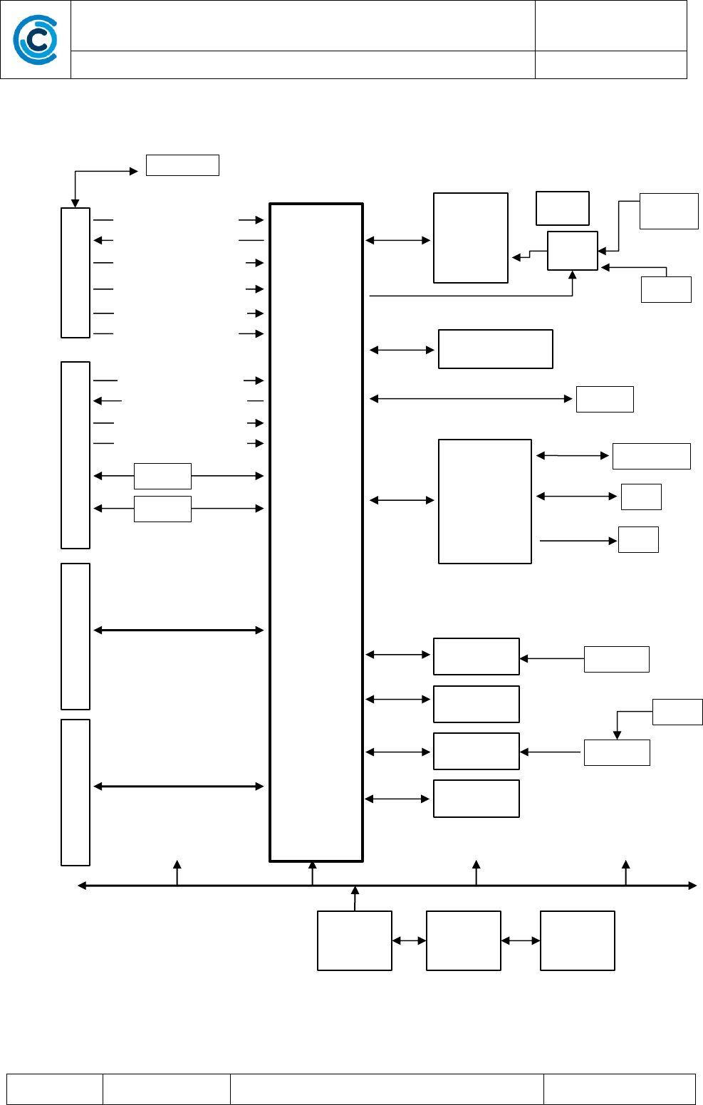
BLOCK DIAGRAM
FIGURE 1 - BLOCK DIAGRAM
Processor
Power
Management
Charging
Circuitry
Battery
GNSS
uBlox M8030
Xtl
Switch
Rf Conn
(Ext)
Antenna
(Int)
External RAM
Ext LEDs
Cellular
(Sarah/
Lisa/
Toby)
Antenna (Int)
LED
SIM
RF
EEPROM
Antenna
RTC
WDT
Accelerometer
Reset gen
Rst Sw
Primary Connector
Pwr / Gnd
Secondary Connector
4 Digital In In 1-4 Ext
2 Digital Out 1-2 Ext
1 Digital In In 5 Ext
1 Digital Out 3 Ext
1 Multi In Bus/Priv/Panic
1 Dallas 1 Wire
1 RS232 Uart
1 Ignition In (ACC)
1 RS232 Uart
1 Analog In Ext
CAN HS
CAN LS
Expansion Connector
Debug Connector

DigiCore Technology (Pty) Ltd
P.O. Box 68270, Highveld Park 0169, South Africa
Manual
Ctrack NX35 Technical Manual
DCT-MAN-296
Revision: 05
03 October 2017
COMPANY CONFIDENTIAL
© DigiCore Technology (Pty) Ltd
Page 11 of 22
2.4.
IDENTIFICATION AND OPTIONS
Model Number
Integrated Cellular Radio Module
NX35-G350
SARA-G350 Cellular Modem (2G)
NX35-U200
LISA-U200 Cellular Modem (3G)
NX35-L200
TOBY-L200 Cellular Modem (LTE)
NX35-C200
LISA-C200 Cellular Modem (CDMA)
DigiCore Technology (Pty) Ltd
P.O. Box 68270, Highveld Park 0169, South Africa
Manual
Ctrack NX35 Technical Manual
DCT-MAN-296
Revision: 05
03 October 2017
COMPANY CONFIDENTIAL
© DigiCore Technology (Pty) Ltd
Page 12 of 22
3. EXTERNAL INTERFACES
3.1.
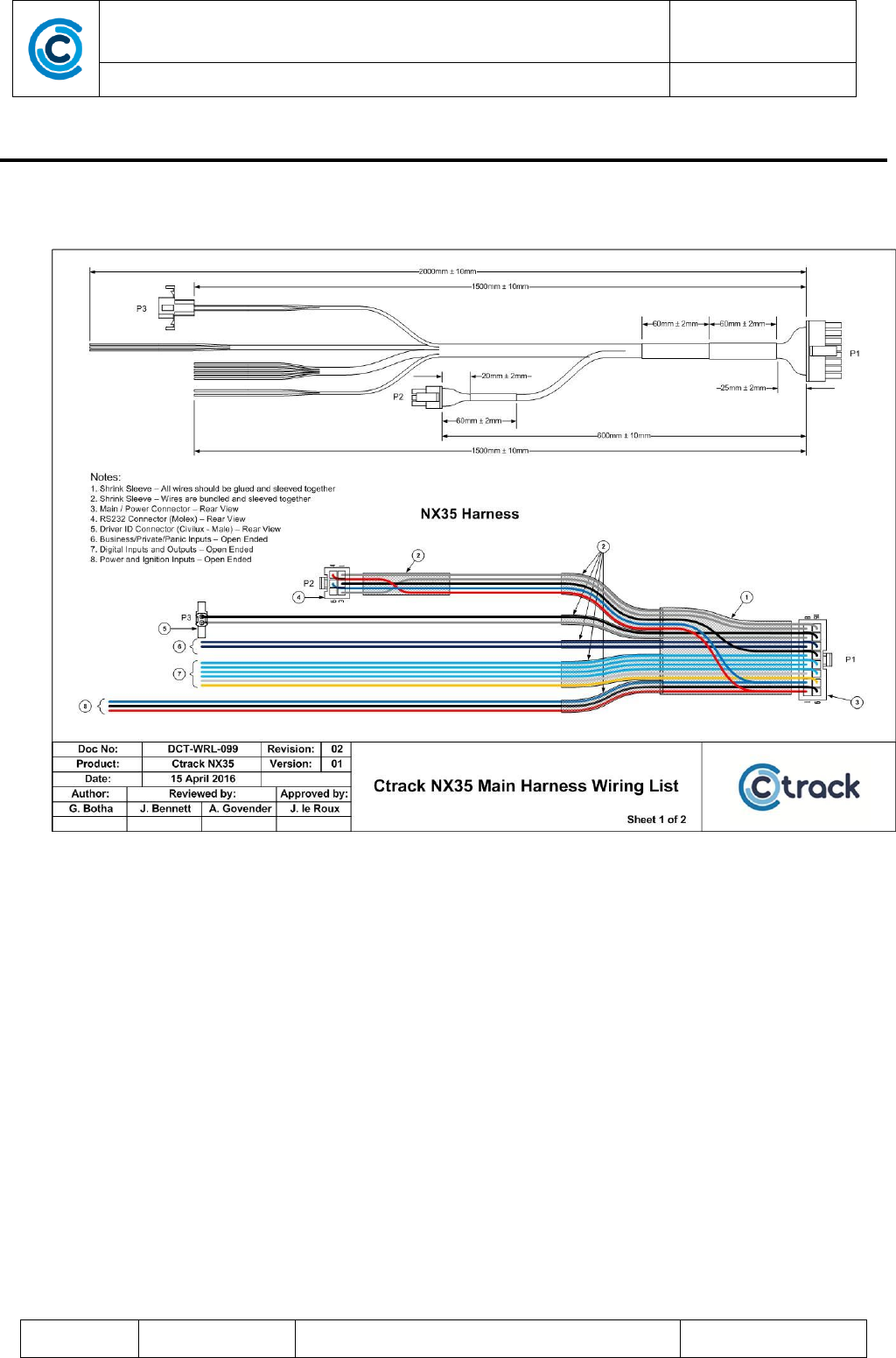
WIRING CONNECTIONS AND CONNECTORS
FIGURE 2 - MAIN HARNESS
DigiCore Technology (Pty) Ltd
P.O. Box 68270, Highveld Park 0169, South Africa
Manual
Ctrack NX35 Technical Manual
DCT-MAN-296
Revision: 05
03 October 2017
COMPANY CONFIDENTIAL
© DigiCore Technology (Pty) Ltd
Page 13 of 22
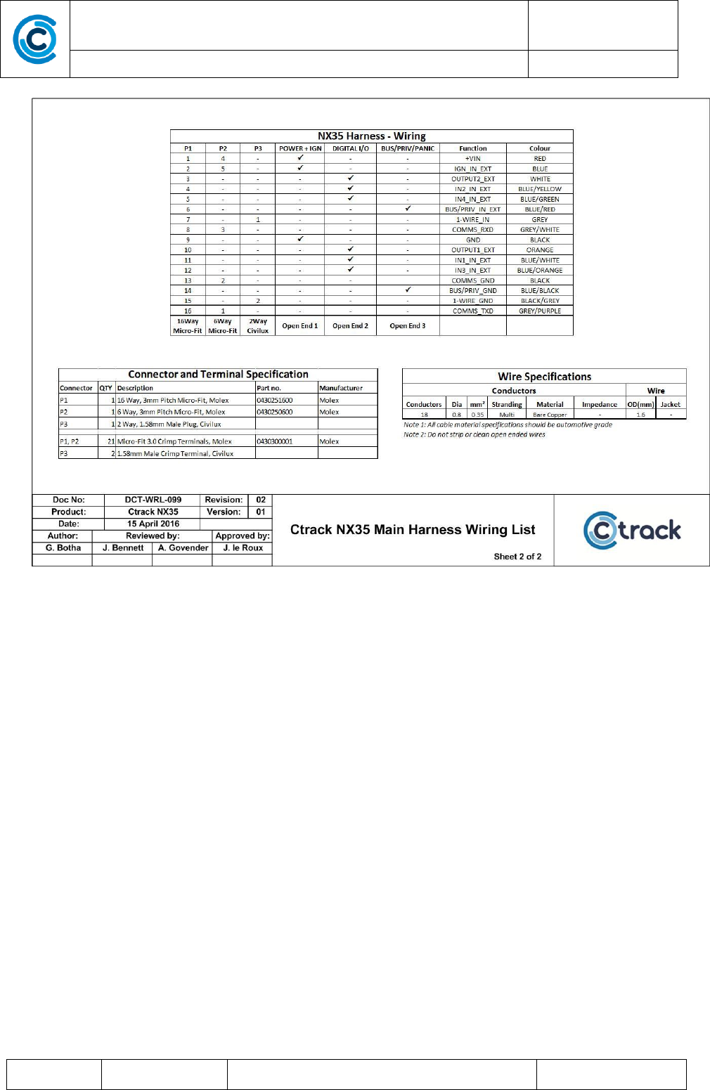
FIGURE 3 – MAIN CONNECTOR SIGNALS
DigiCore Technology (Pty) Ltd
P.O. Box 68270, Highveld Park 0169, South Africa
Manual
Ctrack NX35 Technical Manual
DCT-MAN-296
Revision: 05
03 October 2017
COMPANY CONFIDENTIAL
© DigiCore Technology (Pty) Ltd
Page 14 of 22
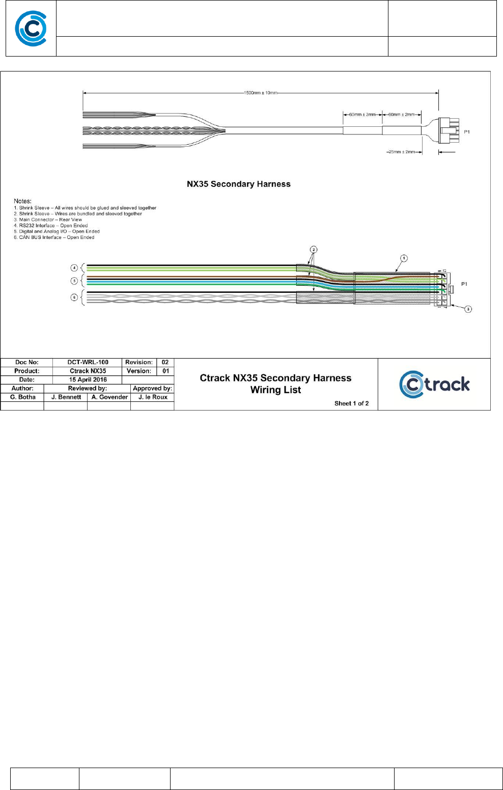
FIGURE 4 - SECONDARY HARNESS
DigiCore Technology (Pty) Ltd
P.O. Box 68270, Highveld Park 0169, South Africa
Manual
Ctrack NX35 Technical Manual
DCT-MAN-296
Revision: 05
03 October 2017
COMPANY CONFIDENTIAL
© DigiCore Technology (Pty) Ltd
Page 15 of 22
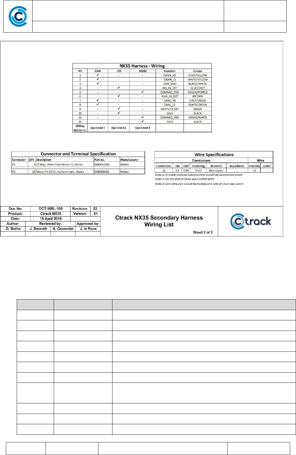
FIGURE 5 – SECONDARY CONNECTOR SIGNALS
3.2.
SIGNAL DESCRIPTION – MAIN/SECONDARY CONNECTOR
The following tables describes the signals with reference to Figure 2 - Main Harness to Figure 5 – Secondary
Connector Signals.
Plug
SIGNAL
DESCRIPTION
Main
+VIN
+VOLTAGE INPUT 6-32VDC
Main
GND
POWER GND
Main
IGN_IN_EXT
IGNITION SENSE - Active High Digital Input
Main
IN1_IN_EXT
INPUT 1 - Active Low Digital Input
Main
IN2_IN_EXT
INPUT 2 - Active Low Digital Input
Main
IN3_IN_EXT
INPUT 3 - Active High Digital Input
Main
IN4_IN_EXT
INPUT 4 - Active High Digital Input
Sec
IN5_IN_EXT
INPUT 5 – Can be used as active low digital input or pulse input
(7KHz maximum pulse)
Main
OUTPUT1_EXT
DIGITAL OUTPUT1 – Immobilizer Output (Open collector)
-
OUTPUT2_EXT
DIGITAL OUTPUT2 – Buzzer Output
Sec
OUTPUT3_EXT
DIGITAL OUTPUT2 – Auxiliary Output (Open collector)
DigiCore Technology (Pty) Ltd
P.O. Box 68270, Highveld Park 0169, South Africa
Manual
Ctrack NX35 Technical Manual
DCT-MAN-296
Revision: 05
03 October 2017
COMPANY CONFIDENTIAL
© DigiCore Technology (Pty) Ltd
Page 16 of 22
Main
BUS/PRIV_IN_EXT
BUSINESS / PRIVATE / PANIC INPUT
Main
BUS/PRIV_GND
BUSINESS / PRIVATE / PANIC GROUND
Main
1-WIRE_IN
DRIVER ID 1 WIRE INPUT
Main
COMMS_TXD
Serial Port 1 RS232 Transmit
Main
COMMS_RXD
Serial Port 1 RS232 Receive
Main
COMMS_GND
Serial Port 1 RS232 GND
Sec
COMMS2_TXD
Serial Port 2 RS232 Transmit
Sec
COMMS2_RXD
Serial Port 2 RS232 Receive
Sec
COMMS2_GND
Serial Port 2 RS232 GND
Sec
ANA_IN_EXT
ANALOGUE INPUT (0-12Volt)
Sec
CANH_HS
High Speed CAN “H” Signal
Sec
CANL_HS
High Speed CAN “L” Signal
Sec
CANH_LS
Low Speed CAN “H” Signal
Sec
CANL_LS
Low Speed CAN “L” Signal
Sec
CAN_GND
CAN GND
3.3.
ENVIRONMENTAL
Certifications
E-Mark, CE-Mark, PTCRB, Australian
Operating Temperature
-20 to 80 deg C
Operating Humidity
95%
3.4.
POWER
Input Voltage
6-32 Vdc
Internal Battery
3.6-4.2 Vdc
Normal Operation – GSM Option +
maximum battery charging
<1A
Normal Operation – CDMA Option +
maximum battery charging
<1A
Sleep Mode
<1 mA
Sleep Mode + maximum battery
charging
< 500mA
DigiCore Technology (Pty) Ltd
P.O. Box 68270, Highveld Park 0169, South Africa
Manual
Ctrack NX35 Technical Manual
DCT-MAN-296
Revision: 05
03 October 2017
COMPANY CONFIDENTIAL
© DigiCore Technology (Pty) Ltd
Page 17 of 22
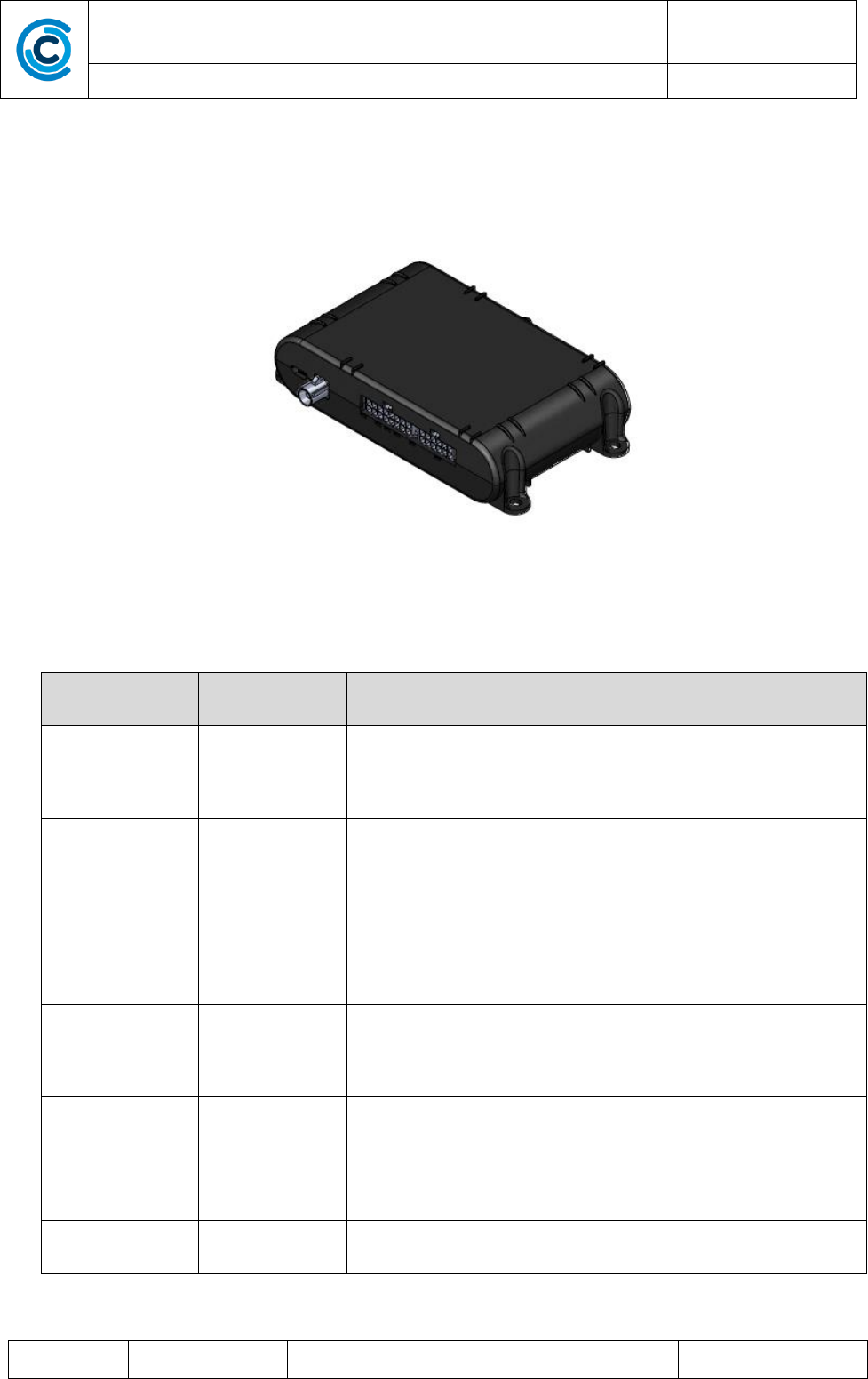
3.5.
MECHANICAL
Dimensions: 131 x 73 x 29mm
Weight: ~ 150g
FIGURE 6 - NX35 PICTURE
3.6.
LEDS
LED
Function
Pattern and function
1-Green
Install State
On- Reading install state
Flash – User installation input required
Off – Ready (see *note)
2-Red
GNSS
On – GNSS on and unlocked
Fast flash – 2D lock
Slow flash – 3D lock
Off – GNSS switched off (see *note)
3- Yellow
Heartbeat
Flash – Firmware running
On –Firmware busy rebooting
4- Red
Cellular
Off- Cellular off or no service
Blip/flashing- Registered on network
On- Data transmit in progress
5-Green
Bluetooth
Off- BT disabled or off (see *note)
On- BT on
Slow flash- BT Discoverable mode
Fast flash- Call in progress
6-Red
File system
On when FFS is accessed
.
DigiCore Technology (Pty) Ltd
P.O. Box 68270, Highveld Park 0169, South Africa
Manual
Ctrack NX35 Technical Manual
DCT-MAN-296
Revision: 05
03 October 2017
COMPANY CONFIDENTIAL
© DigiCore Technology (Pty) Ltd
Page 18 of 22
*Note: 10Minutes after the unit has been finalised and the install tool disconnected, all LEDS will switch off for
security reasons. To switch on the LEDs again, connect an install tool.
3.7.
GNSS
Part
u-blox M8 engine
GPS Receiver
72 channels, GPS/QZSS L1 frequency C/A Code, GLONASS L10F,
BeiDou B1, Galileo E1B/C. SBAS L1 C/A; WAAS, EGNOS, MSAS, GAGAN
Time to first fix
Cold start: 26s
Aided start: 2s
Hot start: 1s
Accuracy
GPS/SBAS/QZSS+GLONASS : 2m
Multi-GNSS Assistance
AssistNow Online
AssistNow Offline
AssistNow Autonomous
Anti-jamming
Active CW detection and removal
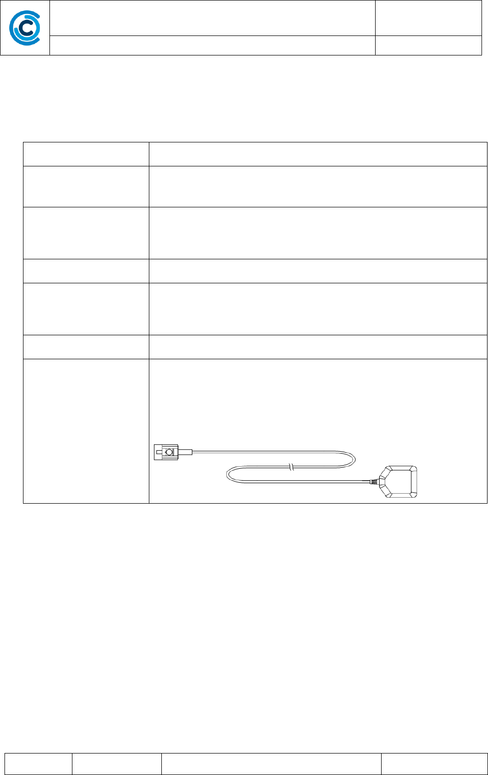
Antenna
External antenna with internal antenna fall back.
Antenna part example (DAM1575A4I10_K3M)
External antenna assembly shown below:
3.8.
CELLULAR
The hardware layout makes provision for populating the following Cellular Modem types:
1. u-blox SARA-G350 (2G)
2. u-blox LISA-U200 (3G)
3. u-blox TOBY-L200 (LTE)
4. u-blox LISA-C200 (CDMA)

DigiCore Technology (Pty) Ltd
P.O. Box 68270, Highveld Park 0169, South Africa
Manual
Ctrack NX35 Technical Manual
DCT-MAN-296
Revision: 05
03 October 2017
COMPANY CONFIDENTIAL
© DigiCore Technology (Pty) Ltd
Page 19 of 22
3.8.1. Option 1 - u-blox SARA-G350 Cellular Module
Quad band support
GSM 850/900/1800/1900 MHz
GPRS
GPRS Class 10, CS1-CS4 – up to 85.6 kb/s. PBCCH support
Circuit Switched Data
Up to 9.6 kbps
Encryption algorithms
A5/1 supported for GSM and GPRS modes
SMS
Mobile-originated and mobile-terminated SMS supported.
Text and PDU modes supported
GSM Jamming detection
Supported
3.8.2. Option 2 - u-blox LISA-U200 Cellular Module
GSM band support
GSM 800/850/900/1700/1900/2100 MHz
GPRS
GPRS Class 12, CS1-CS4 – up to 85.6 kb/s.
EDGE
Class 12, MCS1-9
Circuit Switched Data
GSM Up to 9.6 kbps
Encryption algorithms
A5/1 supported for GSM and GPRS modes
SMS
Mobile-originated and mobile-terminated SMS supported.
Text and PDU modes supported
GSM Jamming detection
Supported
3.8.3. Option 3 - u-blox TOBY-L200 Cellular Module
LTE band support
2,4,5,7,17 (N America)
UMTS
850/900/AWS/1900/2100
GSM
850/900/1800/1900
SMS
Mobile-originated and mobile-terminated SMS supported.
Text and PDU modes supported
GSM Jamming detection
Future

DigiCore Technology (Pty) Ltd
P.O. Box 68270, Highveld Park 0169, South Africa
Manual
Ctrack NX35 Technical Manual
DCT-MAN-296
Revision: 05
03 October 2017
COMPANY CONFIDENTIAL
© DigiCore Technology (Pty) Ltd
Page 20 of 22
3.8.4. Option 4 - u-blox LISA-C200 Cellular Module
CDMA band support
800, 1900 MHz (Sprint, Verizon)
SMS
Mobile-originated and mobile-terminated SMS supported.
Text modes supported
Cellular Jamming
detection
Future
3.9.
BLUETOOTH
®
The unit has an on-board Bluetooth® with the following major features:
Device
BCM20706 (Broadcom), (A2DP, SPP, GATT)
Bluetooth Specifications
Bluetooth v4.2 + EDR with integrated Class 1 PA
Integrated RF
Single-ended, 50-ohm RF interface
Built-in TX/RX switch
Tx class 1 or class2 output power capable
RX sensitivity basic rate of -93.5 dBm
RX sensitivity for Low Energy of -96.5 dBm
Max Transmit Power
< 12 dBm
BT Low Energy
Supported

DigiCore Technology (Pty) Ltd
P.O. Box 68270, Highveld Park 0169, South Africa
Manual
Ctrack NX35 Technical Manual
DCT-MAN-296
Revision: 05
03 October 2017
COMPANY CONFIDENTIAL
© DigiCore Technology (Pty) Ltd
Page 21 of 22
4. INTERNAL COMPONENTS
4.1.
ACCELEROMETER
An on-board 3-axis ±8g accelerometer is used for various movement-detection functions:
1. Vehicle movement
2. Roll over and device tamper
3. Severe and High G-force
4. Harsh driving (acceleration, braking, cornering and up/down)
4.2.
ON-BOARD MEMORY
The on-board memory is as follows:
16 MByte Parallel NOR flash for file system
4 Mbyte RAM
16 Kbit NFC EEPROM for storage of default settings.
4.3.
SIM CARD INTERFACE
On-board SIM card reader with protection and supports 1V8 and 3V SIM cards. An optional second SIM is
provided on the board for future use.
(Not supported for CDMA option.)
4.4.
WATCHDOG
On-board hardware watchdog circuitry to ensure continuous system operation under all conditions.
4.5.
INTERNAL BATTERY
- Uses single Li Polymer 1100mAH battery
- Supplies power to the electronics when external power is removed.
- Automatically charged when external power is connected
- Battery protection consist of over-voltage, under-voltage and over-current. Additional over-temperature
protection is provided by the charger in conjunction with the built-in battery thermistor. The battery cannot
be charged when its temperature is over 55 deg C.

DigiCore Technology (Pty) Ltd
P.O. Box 68270, Highveld Park 0169, South Africa
Manual
Ctrack NX35 Technical Manual
DCT-MAN-296
Revision: 05
03 October 2017
COMPANY CONFIDENTIAL
© DigiCore Technology (Pty) Ltd
Page 22 of 22
5. REGULATORY COMPLIANCE STATEMENTS
5.1.
FEDERAL COMMUNICATIONS COMMISSION (FCC) NOTICE
This equipment has been tested and found to comply with the limits for a Class B digital device, pursuant to
Part 15 of the FCC Rules. These limits are designed to provide reasonable protection against harmful
interference in a residential installation.
This equipment generates uses and can radiate radio frequency energy and, if not installed and used in
accordance with the instructions, may cause harmful interference to radio communications. However, there is
no guarantee that interference will not occur in a particular installation. If this equipment does cause harmful
interference to radio or television reception, which can be determined by turning the equipment off and on, the
user is encouraged to try to correct the interference by one of the following measures:
• Reorient or relocate the receiving antenna.
• Increase the separation between the equipment and receiver.
• Connect the equipment into an outlet on a circuit different from that to which the receiver is connected.
• Consult the dealer or an experienced radio/TV technician for help.
This device complies with part 15 of the FCC Rules. Operation is subject to the following two conditions:
• This device may not cause harmful interference, and
• this device must accept any interference received, including interference that may cause undesired
operation
Any changes or modifications made to this device that are not expressly approved by Ctrack may void your
authority to operate the equipment.
5.2.
INNOVATION SCIENCE AND ECONOMIC DEVELOPMENT (ISED) NOTICE
This device complies with Industry Canada’s Licence-Exempt RSSs. Operation is subject to the following two
conditions:
• This device may not cause interference; and
• This device must accept any interference, including interference that may cause undesired operation
of the device.
Le présent appareil est conforme aux CNR d’Industrie Canada applicables aux appareils radio exempts de
licence. L’exploitation est autorisée aux deux conditions suivantes:
• l’appareil ne doit pas produire de brouillage;
• l’appareil doit accepter tout brouillage radioélectrique subi, même si le brouillage est susceptible d’en
compromettre le fonctionnement.
5.3.
FCC & ISED RF EXPOSURE GUIDANCE SATEMENT
In order to comply with FCC/ISED RF Exposure requirements, this device must be installed to provide at least 20 cm
separation from the human body at all times.
Afin de se conformer aux exigences d'exposition RF FCC / ISED, cet appareil doit être installé pour fournir au moins 20 cm
de séparation du corps humain en tout temps.