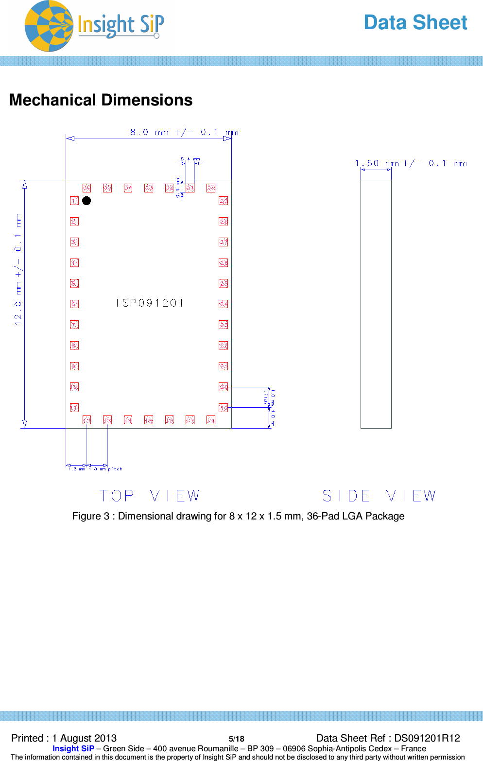
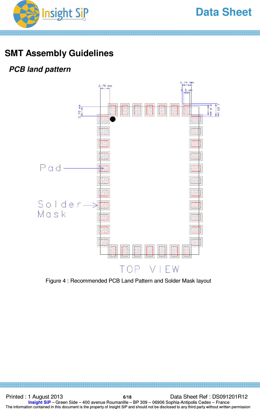
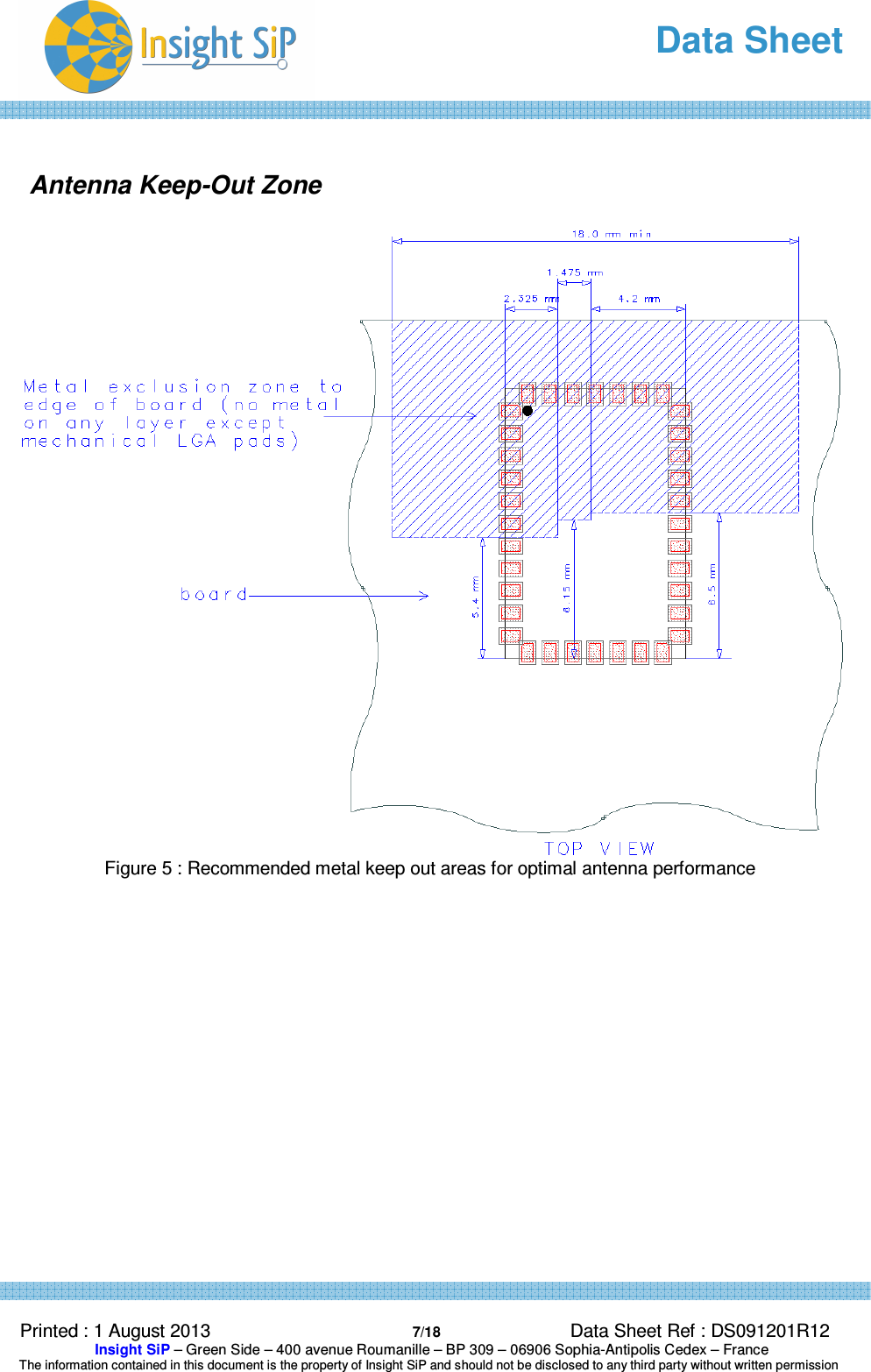
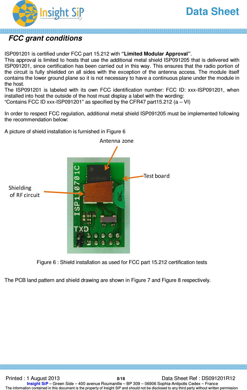
Insight SiP ISP091201 Bluetooth Low Energy Module User Manual DS091201R12x

Insight SiP Bluetooth Low Energy Module DS091201R12x

User manual

  Data Sheet  Printed : 1 August 2013  1/18 Data Sheet Ref : DS091201R12  Insight SiP – Green Side – 400 avenue Roumanille – BP 309 – 06906 Sophia-Antipolis Cedex – France  The information contained in this document is the property of Insight SiP and should not be disclosed to any third party without written permission   ISP091201 Bluetooth Low Energy Module with Integrated Antenna Key Features •  Single Mode Bluetooth Low Energy v4.0 Slave •  Based on Nordic Semiconductor family of uBlue products  •  Includes transceiver, baseband and software stack •  Ultra Low Power Consumption •  Single 1.9 to 3.6 V supply •  Temperature -40 to 85 °C •  Fully integrated RF matching and Antenna •  Integrated 16 MHz Crystal Clock •  FCC Limited Modular Certification 15.212 FCC #2AAQS-ISP091201 •  CE # xxxxxx •  IC # 11306A-ISP091201 •  TELEC # xxxxxx •  Blue Tooth SIG certified # xxxxxx  Applications •  Space constrained Bluetooth Low Energy Slave Devices •  Sport and fitness sensors •  Health care sensors •  Out of Range (OOR) sensors •  Personal User Interface Devices (PUID) •  Remote controls  Description This  module  is  based  on  Nordic  Semiconductor  nRF8001  uBlue  Bluetooth  Low  Energy Platform.  The  nRF8001  is  a  single  chip  transceiver  with  an  embedded  baseband  protocol engine,  suitable  for  ultra  low power wireless  applications  conforming  to  the  Bluetooth  Low Energy  Specification  contained  within  v4.0  of  the  overall  Bluetooth  specification.  The nRF8001D, used in the current revision of ISP091201, is a production product using a RoM for the baseband protocol engine.   * See Product Marking section for up to date module marking
  Data Sheet  Printed : 1 August 2013  2/18 Data Sheet Ref : DS091201R12  Insight SiP – Green Side – 400 avenue Roumanille – BP 309 – 06906 Sophia-Antipolis Cedex – France  The information contained in this document is the property of Insight SiP and should not be disclosed to any third party without written permission  The  uBlue transceiver is specifically designed for both PC peripherals and ultra low  power applications  such  as  sports  and  wellness  sensors.  For  sensor  applications,  the  ultra  low power  consumption  and  advanced  power  management  enables  battery  lifetimes  up  to several years on a coin cell battery.    The  ISP091201  module  size  measures  8  x  12  x  1.5  mm.  The  module  integrates  all  the decoupling capacitors, the 16 MHz crystal and load capacitors plus the RF matching circuit and antenna in addition to the transceiver. As the module has several end applications, the antenna was designed to be compatible with several ground plane sizes including that of a USB  dongle and a cell phone. The module can operate as a standalone  Bluetooth sensor node  with  the  addition  of  a  transducer,  a  small  external  microprocessor  to  run  application software, a 32 kHz crystal and a DC power source.  Functional Block Diagram  The module high level block diagram is shown in Figure 1 below.    Figure 1 : Functional block of the ISP091201 16 MHz Xtal+ capsConfigurable I/O system32 kHz XO16 MHz XOCustom Low Power Micro-controller + Flash MemoryUltra low power2.4 GHzTransceiverAdvanced Power ManagementRF Matching NetworkPower Supply decouplingRF AntennanRF8001 uBlueISP091201VCC32 kHz XtalBLE radiosignalSPI Bus •MOSI•MISO •CSN •SCKReset nRF8001UART RF test mode•TXD•RXDDigital Handshake•ACTIVE•RDY•REQN
  Data Sheet  Printed : 1 August 2013  3/18 Data Sheet Ref : DS091201R12  Insight SiP – Green Side – 400 avenue Roumanille – BP 309 – 06906 Sophia-Antipolis Cedex – France  The information contained in this document is the property of Insight SiP and should not be disclosed to any third party without written permission   Pin Assignment Pin  Name  Pin function  Description 1 – 5  NC  Not Connected  Isolated pad on application PCB for mechanical stability 6  OUT_ANT  Antenna In/Out  This pin is connected to the internal antenna. It should be connected to Pin 7 OUT_MOD for normal operation. During certification the pin may be connected to an RF connector for antenna measurement 7  OUT_MOD  Module In/Out  This pin is the RF I/O pin of the BLE module. It should be connected to Pin 6 OUT_ANT for normal operation. During certification the pin may be connected via to an RF connector for module measurement using a Bluetooth test setup. 8  GND  Ground  Should be connected to ground plane on application PCB 9  NC  Not Connected  Isolated pad on application PCB for mechanical stability 10  MOSI  Digital input  ACI Master Out Slave In 11   DCC  PWM driver  PWM driver for the external LC filter if the DC/DC converter is enabled. If the DC/DC converter is disabled this pin shall be not connected 12  AVDD  Power  Analog power supply (1.9 – 3.6V DC) 13  VCC_nRF  Power  Power supply (1.9 – 3.6V) Supplies the DC/DC converter and GPIOs. VDD in nRF8001 doc. 14  GND  Ground  Should be connected to ground plane on application PCB 15  XL2  Analog output  Connect to external 32.768kHz crystal oscillator (if internal RC oscillator is enabled then leave not connected) 16  XL1  Analog output  Connect to external 32.768kHz crystal oscillator (if internal RC oscillator is enabled then leave not connected) 17  ACTIVE  Digital output  Device RF front end activity indicator 18  TXD  Digital output  UART (transmit) for Bluetooth low energy Direct Test Mode 19  SCK  Digital input  ACI clock input 20  RXD  Digital output  UART (receive) for Bluetooth low energy Direct Test Mode 21  REQN  Digital input  ACI request pin (handshaking, active low) 22  MISO  Digital output  ACI Master In Slave Out 23  GND  Ground  Should be connected to ground plane on application PCB 24  RDYN  Digital output  ACI device ready indication (handshaking) 25  RESET  Digital Input  Reset (Active Low) 26-36  NC  Not Connected  Isolated pad on PCB for mechanical stability
  Data Sheet  Printed : 1 August 2013  4/18 Data Sheet Ref : DS091201R12  Insight SiP – Green Side – 400 avenue Roumanille – BP 309 – 06906 Sophia-Antipolis Cedex – France  The information contained in this document is the property of Insight SiP and should not be disclosed to any third party without written permission   Figure 2 : ISP091201 pin assignment (top view) for the LGA QFN package
  Data Sheet  Printed : 1 August 2013  5/18 Data Sheet Ref : DS091201R12  Insight SiP – Green Side – 400 avenue Roumanille – BP 309 – 06906 Sophia-Antipolis Cedex – France  The information contained in this document is the property of Insight SiP and should not be disclosed to any third party without written permission   Mechanical Dimensions   Figure 3 : Dimensional drawing for 8 x 12 x 1.5 mm, 36-Pad LGA Package
  Data Sheet  Printed : 1 August 2013  6/18 Data Sheet Ref : DS091201R12  Insight SiP – Green Side – 400 avenue Roumanille – BP 309 – 06906 Sophia-Antipolis Cedex – France  The information contained in this document is the property of Insight SiP and should not be disclosed to any third party without written permission   SMT Assembly Guidelines PCB land pattern  Figure 4 : Recommended PCB Land Pattern and Solder Mask layout
  Data Sheet  Printed : 1 August 2013  7/18 Data Sheet Ref : DS091201R12  Insight SiP – Green Side – 400 avenue Roumanille – BP 309 – 06906 Sophia-Antipolis Cedex – France  The information contained in this document is the property of Insight SiP and should not be disclosed to any third party without written permission   Antenna Keep-Out Zone   Figure 5 : Recommended metal keep out areas for optimal antenna performance
  Data Sheet  Printed : 1 August 2013  8/18 Data Sheet Ref : DS091201R12  Insight SiP – Green Side – 400 avenue Roumanille – BP 309 – 06906 Sophia-Antipolis Cedex – France  The information contained in this document is the property of Insight SiP and should not be disclosed to any third party without written permission  FCC grant conditions  ISP091201 is certified under FCC part 15.212 with “Limited Modular Approval”.  This approval is limited to hosts that use the additional metal shield ISP091205 that is delivered with ISP091201, since certification has been carried out in this way. This ensures that the radio portion of the circuit is fully  shielded  on  all  sides  with  the  exception of  the antenna access. The module itself contains the lower ground plane so it is not necessary to have a continuous plane under the module in the host. The  ISP091201  is  labeled  with  its  own  FCC  identification  number:  FCC  ID:  xxx-ISP091201,  when installed into host the outside of the host must display a label with the wording: “Contains FCC ID xxx-ISP091201” as specified by the CFR47 part15.212 (a – VI)  In order to respect FCC regulation, additional metal shield ISP091205 must be implemented following the recommendation below:   A picture of shield installation is furnished in Figure 6   Figure 6 : Shield installation as used for FCC part 15.212 certification tests   The PCB land pattern and shield drawing are shown in Figure 7 and Figure 8 respectively.     Test boardShieldingof RF circuitAntenna zone
  Data Sheet  Printed : 1 August 2013  9/18 Data Sheet Ref : DS091201R12  Insight SiP – Green Side – 400 avenue Roumanille – BP 309 – 06906 Sophia-Antipolis Cedex – France  The information contained in this document is the property of Insight SiP and should not be disclosed to any third party without written permission   Figure 7 : Shield installation land pattern  Parameter description Value in µm a  Shield SM aperture  750 b  Shield metal trace width  500   SM registration (a-b)/2  125 g  Module pad edge to shield trace edge  500 c    2000 d1    2300 d2     3400 e1    4525 e2     3525 f    2250   Pin1
  Data Sheet  Printed : 1 August 2013  10/18 Data Sheet Ref : DS091201R12  Insight SiP – Green Side – 400 avenue Roumanille – BP 309 – 06906 Sophia-Antipolis Cedex – France  The information contained in this document is the property of Insight SiP and should not be disclosed to any third party without written permission    Figure 8 : Mechanical drawing of the shield ISP091205
  Data Sheet  Printed : 1 August 2013  11/18 Data Sheet Ref : DS091201R12  Insight SiP – Green Side – 400 avenue Roumanille – BP 309 – 06906 Sophia-Antipolis Cedex – France  The information contained in this document is the property of Insight SiP and should not be disclosed to any third party without written permission    Electrical Specifications Temperature range -40 to +85 °C   Parameter  Value  Unit Supply voltage Min. Supply Voltage  1.9  V Current consumption Static levels     Peak current, receiver active  14.6  mA Peak current, transmitter active  12.7  mA Current drain, connection-less state  0.5  µA Current drain between connection events  2  µA RF performances Parameter  Value  BT V4 standard limit Unit  Condition Output Power  -0.9 -20 to 10  dBm  Channels 0 to 39 RF Frequency tolerance Better than +/-20  +/- 50  Hz  Channel 0 to 39 Rx sensitivity  -85  -70  dBm  Level for BER <0,1% Max range   > 20    m  Open field at 1m height EIRP  0.3   dBm   Antenna Gain  1.2   dBi   Rx sensitivity  58.8    dBµV/m
  Data Sheet  Printed : 1 August 2013  12/18 Data Sheet Ref : DS091201R12  Insight SiP – Green Side – 400 avenue Roumanille – BP 309 – 06906 Sophia-Antipolis Cedex – France  The information contained in this document is the property of Insight SiP and should not be disclosed to any third party without written permission  Electrical Schematic    Figure 9 : Electrical schematic showing module connections to nRF8001 device RXD SCK REQNVCC_nRFTXDACTIVEXL1XL2OUT_ANTOUT_MODRESETRDYNMISOMOSIAVDDAVDDDCCVCC_nRFC120201TC90201C70201C80201GND12TGND13TGND14TGND15TAnt1C60201L30201C50201GND5TL10201L20201TC30201NC55GND9TGND8TGND24TGND17TC10201R10201Y1NX2520 SA4132GND1TC20201GND20TGND4TGND3TGND18TC110201GND19TU1nRF8001_TnRF80011733DCC32VSS631VSS530AVDD329XC128XC227AVDD226IREF25AVDD1 24VSS4 23ANT2 22ANT1 21VDD_PA 20RESET 19VSS3 18VSS2RDYN16NC15MISO14MOSI13REQN12SCK11RXD10VDD19VSS18TXD7ACTIVE6XL15XL24DEC23DEC12VDD1GND_EPGND25TGND11TTOP VIEWOUT_ANTVCC_nRFAVDD XL2 XL1 ACTIVE TXDSCKMOSI RXDREQNMISOOUT_MODOUT_ANT RDYNRESETI / OACTIVEIO PinAVDDIO PinVCC_nRFIO PinVSSIO PinXL2IO PinXL1IO PinTXDIO PinNC11IO PinNC8IO PinNC7IO PinNC4IO PinVSS1IO PinMISOIO PinREQNIO PinRXDIO PinSCKIO PinRDYNIO PinRESETIO PinNC36IO PinNC35IO PinNC32IO PinNC31IO PinNC28IO PinNC27IO PinNC24IO PinNC5IO PinNC23IO PinNC20IO PinNC19IO PinNC16IO PinNC15IO PinOUT_MODIO PinOUT_ANTIO PinVSS2IO PinMOSIIO PinDCCIO PinNC54NC50NC51NC52NC53NC43 NC44 NC45 NC46 NC47 NC48 NC49NC37NC38NC39NC40NC41GND22BGND23BGND21B
  Data Sheet  Printed : 1 August 2013  13/18 Data Sheet Ref : DS091201R12  Insight SiP – Green Side – 400 avenue Roumanille – BP 309 – 06906 Sophia-Antipolis Cedex – France  The information contained in this document is the property of Insight SiP and should not be disclosed to any third party without written permission   Typical Antenna Pattern & Return Loss  Return loss  Figure 10 : Antenna return loss measurement                            2.1 2.2 2.3 2.4 2.5 2.6 2.7 2.8 2.92.0 3.0-12-6-180freq, GHzdB(S(1,1))
  Data Sheet  Printed : 1 August 2013  14/18 Data Sheet Ref : DS091201R12  Insight SiP – Green Side – 400 avenue Roumanille – BP 309 – 06906 Sophia-Antipolis Cedex – France  The information contained in this document is the property of Insight SiP and should not be disclosed to any third party without written permission   Radiation Pattern           Figure 11 : Radiation pattern in 3 planes                     -40-30-20-100gain (dBi) @ 2.45GHzzθ=0°θ=90°yxyz-40-30-20-100gain (dBi) @ 2.45GHzzθ=0°θ=90°xxyz-40-30-20-100gain (dBi) @ 2.45GHzϕ=0°ϕ=90°yxxyz
  Data Sheet  Printed : 1 August 2013  15/18 Data Sheet Ref : DS091201R12  Insight SiP – Green Side – 400 avenue Roumanille – BP 309 – 06906 Sophia-Antipolis Cedex – France  The information contained in this document is the property of Insight SiP and should not be disclosed to any third party without written permission   Ground Plane Effect                   USB dongle ground plane        Cell phone config 1 ground plane           Cell phone config 1 with side ground plane    (size : 18 x 30 mm²)                (size : 40 x 100 mm²)                            (size : 40 x 100 mm²)                               Cell phone config 2 with side ground plane           Cell phone config 3 with side ground plane                      (size : 40 x 100 mm²)               (size : 40 x 100 mm²)       Figure 12 : Ground plane effect simulation
  Data Sheet  Printed : 1 August 2013  16/18 Data Sheet Ref : DS091201R12  Insight SiP – Green Side – 400 avenue Roumanille – BP 309 – 06906 Sophia-Antipolis Cedex – France  The information contained in this document is the property of Insight SiP and should not be disclosed to any third party without written permission   USA – User information This intends to inform how to specify the FCC ID of our module “ISP091201” on the product. Based on the Public Notice from FCC, the host device should have a label which indicates that it contains our module. The label should use wording such as: “Contains FCC ID: 2AAQS-ISP091201”. Any similar wording that expresses the same meaning may be used. The label of the host device should also include the below FCC Statement. When it is not possible, this information should be included in the User Manual of the host device : “This device complies with part 15 of the FCC rules. Operation is subject to the following two conditions. (1) This device may not cause harmful interference (2) This device must accept any interference received, including interference that may cause undesired  operation. Caution: Any Changes or modifications not expressly approved by the party responsible for compliance could void the user’s authority to operate the equipment.”   CANADA – User information This intends to inform how to specify the IC ID of our module “ISP091201” on the product. According to  Canadian  standards  “RSS-210”  and  “RSS-Gen”,  the  host  device  should  have  a  label  which indicates that it contains our module.  The label should use wording such as: “Contains IC: 11306A-ISP091201”. Any similar wording that expresses the same meaning may be used. The label of the host device should also include the below IC Statement. When it is not possible, this information should be included in the User Manual of the host device : This device complies with Industry Canada licence-exempt RSS standard(s). Operation is subject to the following two conditions: (1) this device may not cause interference, and (2) this device must accept any interference, including interference that may cause undesired operation of the device.  Le présent appareil est conforme aux CNR d'Industrie Canada applicables aux appareils radio exempts de licence. L'exploitation est autorisée aux deux conditions suivantes : (1) l'appareil ne doit pas produire de brouillage, et (2) l'utilisateur de l'appareil doit accepter tout brouillage radioélectrique subi, même si le brouillage est susceptible d'en compromettre le fonctionnement
  Data Sheet  Printed : 1 August 2013  17/18 Data Sheet Ref : DS091201R12  Insight SiP – Green Side – 400 avenue Roumanille – BP 309 – 06906 Sophia-Antipolis Cedex – France  The information contained in this document is the property of Insight SiP and should not be disclosed to any third party without written permission   Label location The labels are permanently laser marked following the figure bellow:         Model: ISP091201YYWW  FCC ID: 2AAQS-ISP091201CE1 mm4 mmIC: 11306A-ISP0912012 mm2 mm2 mm3 mm3 mm
  Data Sheet  Printed : 1 August 2013  18/18 Data Sheet Ref : DS091201R12  Insight SiP – Green Side – 400 avenue Roumanille – BP 309 – 06906 Sophia-Antipolis Cedex – France  The information contained in this document is the property of Insight SiP and should not be disclosed to any third party without written permission   Ordering  Information Package marking  I  S P  0  9 1 2 0 1 D Y Y W W             Abbreviation  ISP091201  Product number D  Hardware version YY   Two digit year number WW  Two digit week number    Moisture Sensitivity  Since  the  device  package  is  sensitive  to  moisture  absorption,  it  is  necessary  to  do  baking  before assembly. The standard baking condition is 125°C/24 hours.

Navigation menu